

HIT 2SH20 Datasheet
Application
High speed power switching
Features
• High speed switching
• Low on saturation voltage
Table 1 Absolute Maximum Ratings (Ta = 25°C)
Item Symbol Ratings Unit
———————————————————————————————————————————
Collector to emitter voltage V
CES
600 V
———————————————————————————————————————————
Gate to emitter voltage V
GES
±20 V
———————————————————————————————————————————
Collector current I
C
36 A
———————————————————————————————————————————
Collector peak current ic(peak) 60 A
———————————————————————————————————————————
Collector dissipation PC* 100 W
———————————————————————————————————————————
Channel temperature T
j
150 °C
———————————————————————————————————————————
Storage temperature Tstg –55 to +150 °C
———————————————————————————————————————————
* Value at Tc = 25°C
1. Gate
2. Collector
3. Emitter
TO–3P
1
2
3
1
2
3
1
2SH20
Silicon N-Channel IGBT
1st. Edition
Feb. 1995
ADE–208–293 (Z)

Table 2 Electrical Characteristics (Ta = 25°C)
Item Symbol Min Typ Max Unit Test conditions
———————————————————————————————————————————
Collector to emitter breakdown V
(BR)CES
600 — — V IC= 100 µA, VGE= 0
voltage
———————————————————————————————————————————
Zero gate voltage collector I
CES
— — 0.5 mA VCE= 600 V, VGE= 0
current
———————————————————————————————————————————
Gate to emitter leak current I
GES
——±1µAVGE= ±20 V, VCE= 0
———————————————————————————————————————————
Gate to emitter cutoff current V
GE(off)
3.0 — 6.0 V IC= 1 mA, VCE= 10 V
———————————————————————————————————————————
Collector to emitter saturation V
CE(sat)
1 — 1.5 — V IC= 15 A, VGE= 15 V
voltage
———————————————————————————————————————————
Collector to emitter saturation V
CE(sat)
2 — 2.0 2.6** V IC= 30 A, VGE= 15 V
voltage
———————————————————————————————————————————
Input capacitance Cies — 2600 — pF VCE= 10 V, VGE= 0,
f = 1 MHz
———————————————————————————————————————————
Switching time t
r
— 160 — ns IC= 30 A,
————————————————
t
on
— 300 — RL= 10 Ω,
————————————————
t
f
— 2000 — VGE= ±15 V
————————————————
t
off
— 2500 — Rg = 50 Ω
———————————————————————————————————————————
**V
CE(sat)
2 is specified at the correlated test condition (IC=20A)
2
2SH20
3
2SH20
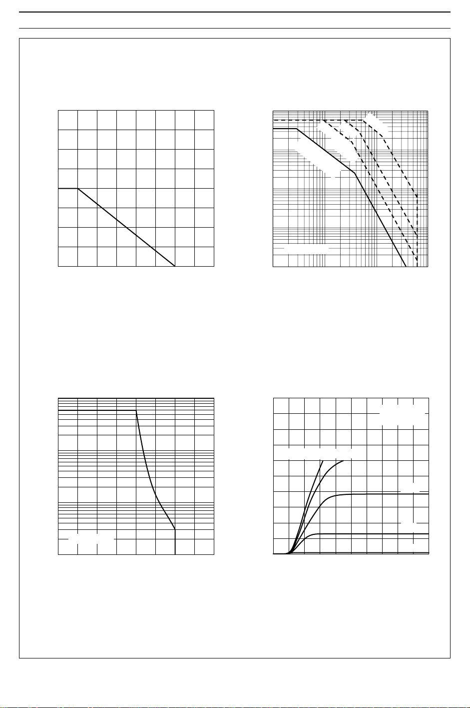
200
Power vs. Temperature Derating
150
100
50
Collector Dissipation Pc (W)
0
50 100 150 200
Case Temperature Tc (°C)
Reverse Bias SOA
100
C
10
100
C
10
PW = 10 ms
(1 shot)
DC Operation
(Tc = 25 °C)
1 ms
100 µs
1
Maximum Safe Operation Area
0.1
Collector Current I (A)
Ta = 25 °C
0.01
1 10 100 1000
Collector to Emitter Voltage V (V)
Typical Output Characteristics
100
Pulse Test
Ta = 25 °C
80
C
60
V = 15 V
GE
12 V
CE
1
Collector Current I (A)
Tc = 25 °C
0.1
0 200 400 600 800
Collector to Emitter Voltage V (V)
CE
40
20
Collector Current I (A)
10 V
8 V
6 V
0426810
Collector to Emitter Voltage V (V)
CE
 Loading...