

HIT 2SC5543 Datasheet
VHF / UHF wide band amplifier
Features
• Super compact package;
(1.4 × 0.8 × 0.59mm)
• Capable low voltage operation ;
(VCE = 1V)
Outline
2SC5543
Silicon NPN Epitaxial
ADE-208-690 (Z)
1st. Edition
Nov. 1998
Note: Marking is “YA-”.
MFPAK
3
1
2
1. Emitter
2. Base
3. Collector
2SC5543
C
C
C
Absolute Maximum Ratings (Ta = 25°C)
Item Symbol Ratings Unit
Collector to base voltage V
Collector to emitter voltage V
Emitter to base voltage V
Collector current I
CBO
CEO
EBO
C
Collector power dissipation Pc 80 mW
Junction temperature Tj 150 °C
Storage temperature Tstg –55 to +150 °C
Electrical Characteristics (Ta = 25°C)
Item Symbol Min Typ Max Unit Test Conditions
Collector cutoff current I
Collector cutoff current I
Emitter cutoff current I
DC current transfer ratio h
CBO
CEO
EBO
FE
Collector output capacitance Cob — 0.51 0.9 pF V
Gain bandwidth product f
T
Power gain PG 11 13.7 — dB V
Noise figure NF — 1.1 2.5 dB V
——10µAV
——1 mAV
——10µAV
85 — 170 V VCE = 1V , IC = 5mA
5.5 8.5 — GHz VCE = 1V , IC = 5mA
15 V
8V
1.5 V
20 mA
= 15V , IE = 0
CB
= 8V , RBE = ∞
CE
= 1.5V , IC = 0
EB
= 1V , IE = 0
B
f = 1MHz
= 1V, IC = 5mA
E
f = 900MHz
= 1V, IC = 5mA
E
f = 900MHz
2
2SC5543
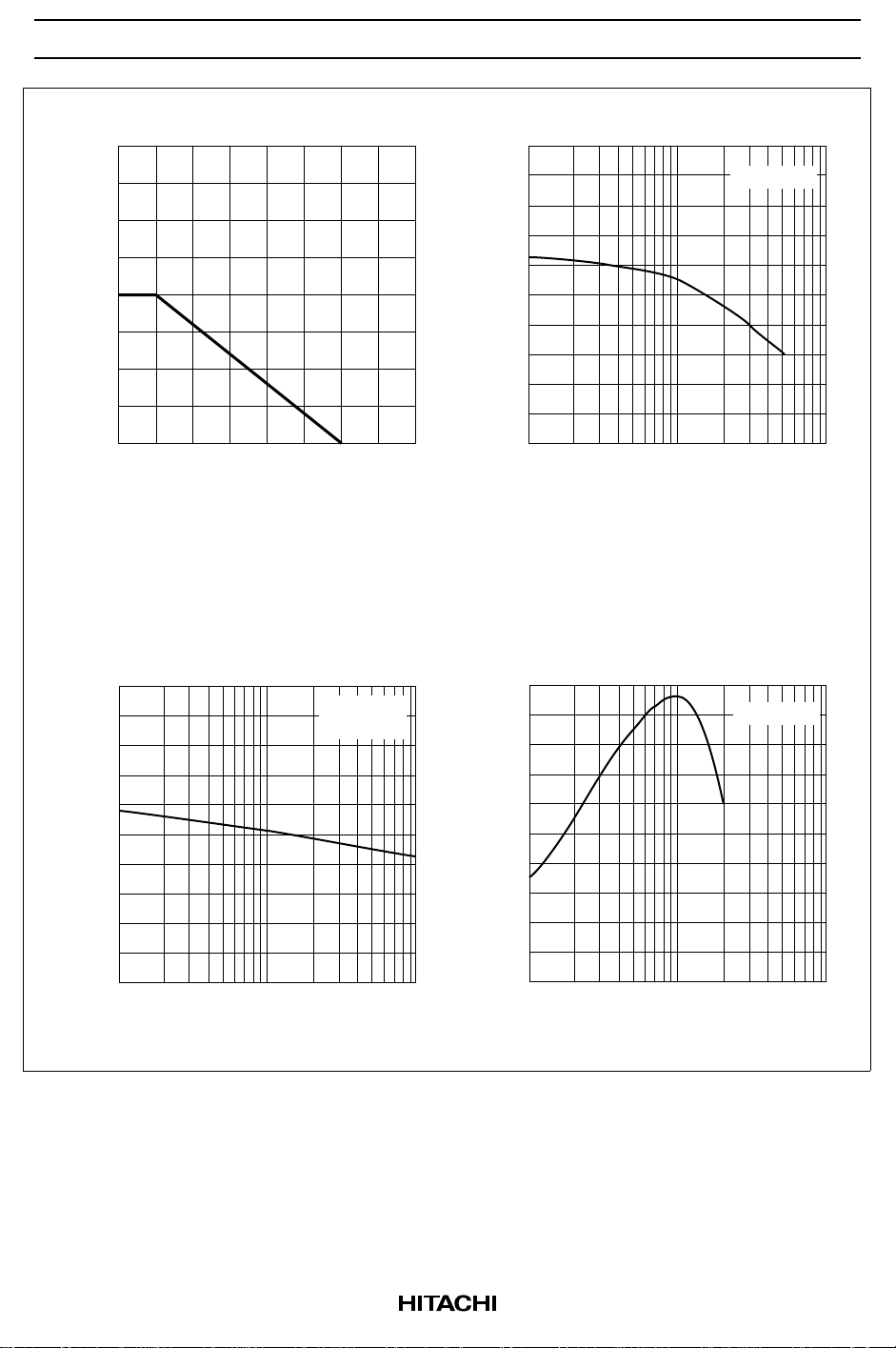
Maximum Collector Dissipation Curve
160
120
80
40
Collector Power Dissipation Pc (mW)
0
50 100 150 200
Ambient Temperature Ta (°C)
Collector Output Capacitance vs.
1.0
0.8
Collector to Base Voltage
I = 0
f = 1MHz
DC Current Transfer Ratio vs.
200
FE
Collector Current
V = 1 V
CE
100
DC Current Transfer Ratio h
0
50
25
1
Collector Current I (mA)
10
20
C
100
Gain Bandwidth Product vs.
10
E
Collector Current
V = 1 V
CE
8
T
0.6
0.4
0.2
0
Collector Output Capacitance Cob (pF)
0.2 0.5 2
0.1 1 10
Collector to Base Voltage V (V)
CB
6
4
2
Gain Bandwidth Product f (GHz)
0
5
12 5
Collector Current I (mA)
10 20
50 100
C
3
 Loading...