

Hisun HS400UTV Service Manual

Forth version , May, 2014
Published by Chongqing
Huansong Industries
(Group) Co., Ltd and
Hisun Motors Corp USA.
Chongqing Huansong
Industries (Group)
Co., Ltd and Hisun
Motors Corp USA
holds the copy right.
No publishing and
reprinting without
permission
READ THIS
MANUAL
CA RE F UL LY
For questions regarding
this UTV, please
contact HISUN at:
(877) 838-6188
www.hisunmotors.com
REV. 06051401
SERVICE
MANUAL
HS400

Foreword
Brief introduction to maintenance handbook of
HS400UTV
The handbook is edited by Technical Center of Chongqing Huansong Industries (Group)
Co., Ltd., and is supplied to dealers and technicians as a document of technique.
This manual gives methods to check, maintain and repair utility terrain vehicles (UTV’s),
and supplies some relevant techniques and performance data. Some
techniques and methods inside may be used to check, maintain and repair other models
of UTV, although it is mainly for the HS400UTV.
Please read the handbook through and fully understand it; otherwise, any improper
repairing could bring you problems, and or an accident may occur.
Proper use and maintenance can guarantee the UTV being driven safely, reduce its
malfunctions, and help the vehicle remain at its best performance level.
The standards, procedures and specifications mentioned in this manual are based on
the sample in design, and they are subject to changes according to the product’s
improvement without prior notice.
Second version , May, 2014
Published by Chongqing Huansong Industries (Group) Co., Ltd.
Chongqing Huansong Industries (Group) Co., Ltd holds the copy right.
No publishing and reprinting without permission.
INDEX
1.
Index
Chapter 2
Specifications
Chapter 4
Engine
Chapter 6
Electrical
2.
3.
Chapter 1
General
Chapter 3
Periodic
Maintenance and
Adjustments
Chapter 5
Chassis
Chapter 7
Engine
Management
System
Chapter 8
Troubleshooting
Wiring
Diagrams
???

INDEX

INDEX
Chapter 1 General
Idle
Adjustment
3-6
Warnings, Cautions, Notes
Description
Identification Code, Frame
Number, Engine Number
Safety
Handling Gasoline safely
Cleaning Parts, Warning Labels,
Serial Numbers, Fasteners
Self locking Fasteners, Cotter
Pins
Snap Rings and E-clips
Shop Supplies
Basic Tools
Wrenches
Torque Wrenches
Ignition Grounding Tool
Precision Measuring Tools
Micrometers
Cylinder Bore Gauge,
Compression Gauge
Electrical System Fundamentals
Basic Service Methods
Storage
Chapter 2 Specifications
Conversion table
General Specs
Engine Specs
Chassis Specs
Electrical Specs
Engine Torque Specs
Chassis Torque Specs
General Torque Specs
Engine Lubrication Points and
type of lubricant
Chassis Lubrication Points and
types of lubricant
Chapter 3
Maintenance schedule
Valve Adjustment
1-3
1-4
1-5
1-6
1-7
1-8
1-9
1-10
1-11
1-13
1-14
1-17
1-19
1-20
1-21
1-26
1-27
1-27
1-36
2-3
2-4
2-6
2-11
2-14
2-16
2-19
2-21
2-22
2-23
3-3
3-5
Spark Plug, Compression test
Engine Oil
Air filter
Coolant level
V-Belt
Spark arrester
Brake Pedal
Brake Pads
Brake Lines
Shift Lever Adjustment
Final Gear oil
Steering system
Tires
Shock Absorbers
Headlight adjustment
Chapter 4 Engine
Engine Notes
Engine removal
Cylinder head and Cylinder head
cover
Rocker Arms and camshaft
Valves and valve springs
Cylinder and Piston
Engine cooling fan and A.C.
magneto
Balancer Gears and Oil Pump
Gears
Primary and Secondary Sheaves
Primary Sheave
Secondary Sheave
Clutch
Clutch Housing Assembly
Crankcase, Starter Motor and Oil
Filter
Crankcase
Crankcase Bearings
Crankshaft and oil Pump
Oil Pump
Transmission
Drive Axle Assembly
Middle Drive shaft
Middle Driven shaft
Intake Manifold Assembly
3-7
3-8
3-10
3-11
3-15
3-16
3-16
3-18
3-19
3-20
3-21
3-23
3-24
3-25
3-27
4-3
4-4
4-5
4-9
4-13
4-18
4-22
4-27
4-29
4-30
4-31
4-35
4-36
4-39
4-41
4-42
4-45
4-46
4-49
4-50
4-53
4-54
4-58

INDEX
Chapter 5 Chassis
Signal System Circuit
D
iagram
,
6-27
Front Bumper and Hood
Panels and Footrest cover
Seat Support and seat cushion
Roll-over Protection System
Cargo Bed
Steering System
Brake System
Front Brake discs
Rear Brake Caliper
Front Wheel
Rear Wheel
Front Bridge
Rear Bridge
Gearshift, Parking Brake
Pedal Assembly
Front Suspension
Front Arm
Rear Suspension
Rear A arm assembly
Cooling System
Water Pump
Seat
Fuel Tank
Chapter 6 Electrical
Electrical Components
Battery Basics
Charging a Lead Acid Battery
Charging a Maintenance Free
Battery
Testing a Switch
Switch Continuity
Bulbs and Bulb Sockets
Ignition System Circuit Diagram,
troubleshoot
Electric Start Circuit Diagram,
troubleshoot
Charging System Circuit
Diagram, troubleshoot
Lighting System Circuit
Diagram, troubleshoot
5-3
5-4
5-5
5-6
5-7
5-9
5-15
5-16
5-20
5-26
5-27
5-30
5-38
5-41
5-46
5-48
5-50
5-54
5-55
5-57
5-61
5-64
5-67
6-3
5-5
6-6
6-8
6-9
6-10
6-11
6-12
6-16
6-21
6-23
troubleshoot
Cooling System Circuit Diagram,
troubleshoot
2WD/4WD Selecting System
Circuit Diagram, troubleshoot
Chapter 7 EMS (Engine
Management System)
EMS Introduction, Components
Layout
ECU
Multec 3.5 Injectors
Throttle Body assembly
Engine coolant temperature
sensor, Oxygen sensor
Fuel Pump Module
Fault Codes
Chapter 8 Troubleshoot
Diagnosing electrical and
mechanical problems
Spark Test
Fuel System
Preignition, Detonation and
Engine noises
Cylinder Leak Down Test
Electrical Testing, Preliminary
checks and precautions
Intermittent Problems
ECU
Wiring Diagrams
6-34
6-37
7-3
7-4
7-4
7-5
7-7
7-8
7-9
7-12
8-3
8-4
8-5
8-7
8-8
8-10
8-11
8-12
General
Warnings, Cautions, Notes
1-3
Basic Tools
1-13
Description
Identification Code, Frame
Number, Engine Number
Safety
Handling Gasoline safely
Cleaning Parts, Warning Labels,
Serial Numbers, Fasteners
Self locking Fasteners, Cotter
Pins
Snap Rings and E-clips
Shop Supplies
1-4
1-5
1-6
1-7
1-8
1-9
1-10
1-11
Wrenches
Torque Wrenches
Ignition Grounding Tool
Precision Measuring Tools
Micrometers
Cylinder Bore Gauge,
Compression Gauge
Electrical System
Fundamentals
Basic Service Methods
Storage
1-14
1-17
1-19
1-20
1-21
1-26
1-27
1-27
1-36
1-1

General
1-2

General
General Information
The text provides complete information on maintenance, tune-up repair and overhaul,
Hundreds of photographs and illustrations created, during the complete disassembly of
four wheel all-terrain vehicles (UTV), guide the reader through every job. All procedures
are in step-by-step format and designed for the reader who may be working on the UTV
for the first time.
WARNINGS, CAUTIONS AND NOTES
The terms WARNING, CAUTION and NOTE have specific meaning in this manual.
Warning: emphasizes areas where injury or even death could result from
negligence. Mechanical damage may also occur. Warnings are to be
taken seriously.
Caution: emphasizes areas where equipment damage could result. Disregarding
a Caution could cause permanent mechanical damage, though injury is
unlikely.
Note: provides additional information to make a step or procedure easier or
clearer. Disregarding a Note could cause inconvenience, but would not
cause equipment damage or injury.
1-3
General
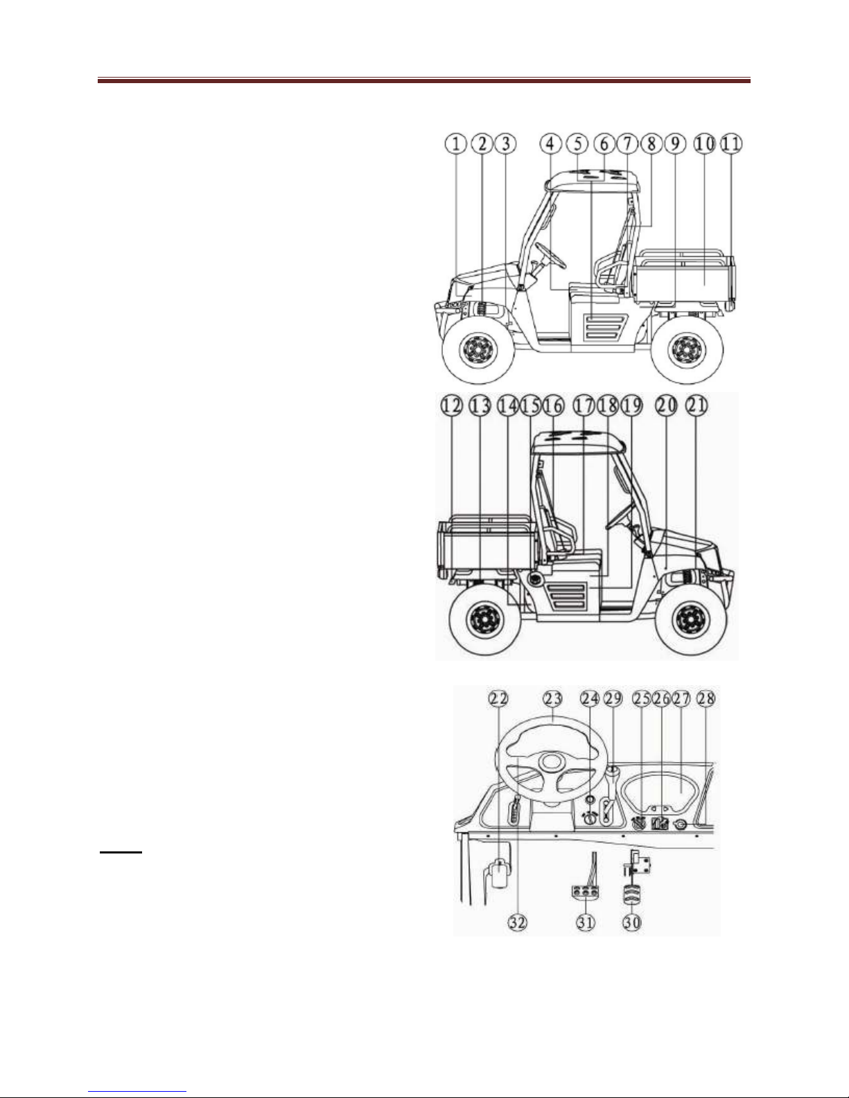
Description
1. Headlights
2. Front shock absorber assembly
3. Brake fluid reservoir
4. Driver seat
5. Battery
6. Fuses
7. Left body protection plate
8. Driver seat belt
9. Air filter element
10. Cargo bed
11. Tail/brake lights
12. Spark arrester
13. Rear shock absorber assembly
14. CVT-belt case
15. Fuel tank cap
16. Passenger seat belt
17. Right body protection plate
18. Spark plug
19. Oil filter cartridge
20. Radiator cap
21. Coolant reservoir
22. Parking brake lever
23. Steering wheel
24. Ignition switch
25. Light switch
26. On-Command four-wheel-drive
and differential lock switches
27. Multi-function display gauge
28. Auxiliary DC jack
29. Drive select lever
30. Accelerator pedal
31. Brake pedal
32. Release parking handle
Note:
The vehicle you have purchased may
differ slightly from those in the figures
of this manual.
1-4
General
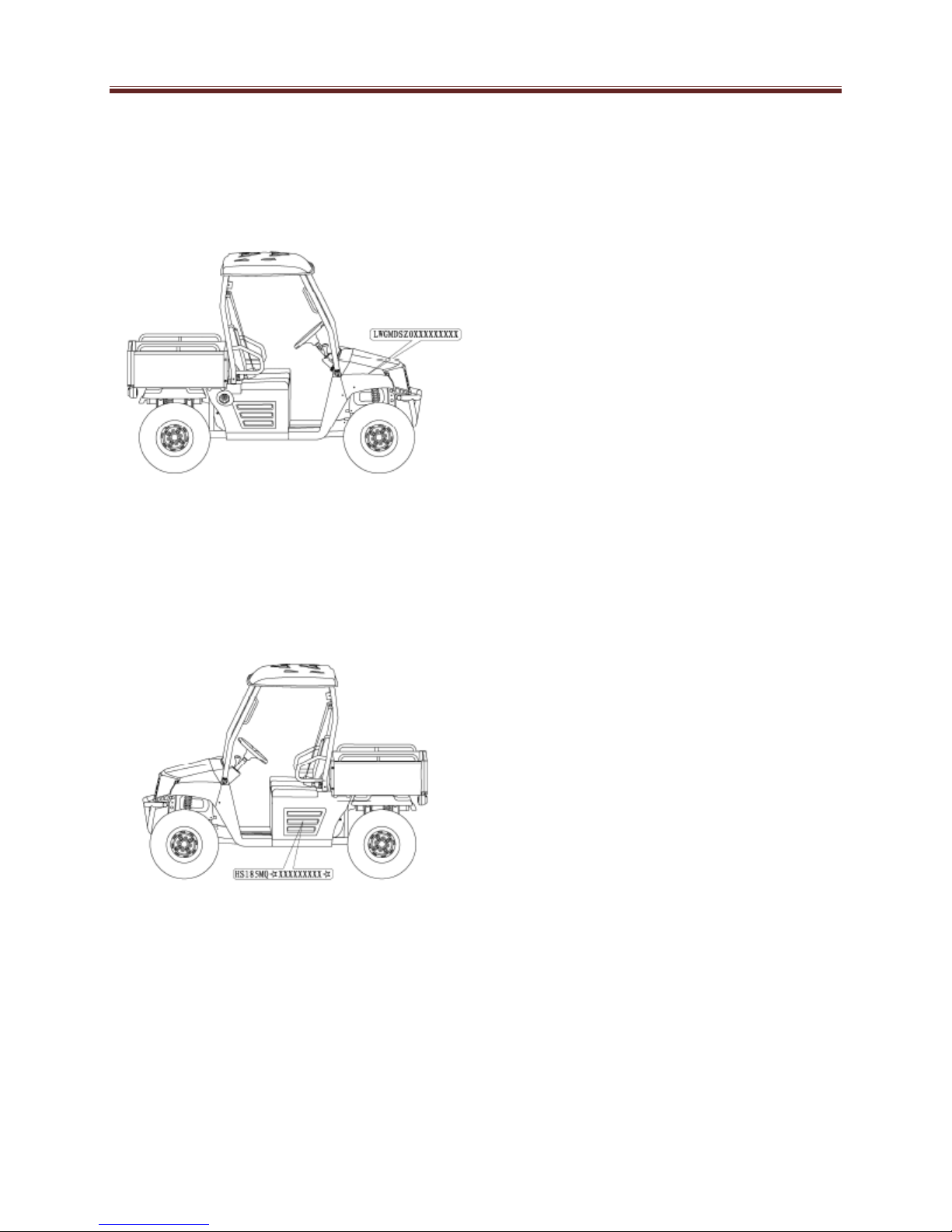
Identification Code
Frame No.
Frame No. is carved on the right side of
front main frame.
Engine No.
Engine NO. Is carved on the right side
of the engine.
1-5

General
Safety
Professional mechanics can work for
years and never sustain a serious injury
or mishap. Follow these guidelines and
practice common sense to safely service
the utility terrain vehicles.
1. Do not operate the utility terrain
vehicle in an enclosed area. The
exhaust gasses contain carbon
monoxide, an odorless, colorless
and tasteless poisonous gas.
Carbon monoxide levels build up
quickly in small enclosed areas
and can cause unconsciousness
and death in a short time. Make
sure to properly ventilate the
work area or operate the UTV
outside.
2. Never use gasoline or any
extremely flammable liquid to
clean parts. Refer to cleaning
parts and handling Gasoline
Safely in this section.
3. Never smoke or use a torch in
the vicinity of flammable liquids,
such as gasoline or cleaning
solvent.
4. If welding or brazing on the UTV,
move the fuel tank to a safe
distance at least 50ft.(15m)
away.
5. Use the correct type and size of
tools to avoid damaging
fasteners.
6. Keep tools clean and in good
condition. Replace or repair worn
or damaged equipment.
7. When loosening a tight fastener,
be guided by what would happen if
the tool slips.
8. When replacing fasteners, make
sure the new fasteners are the
same size and strength as the
original ones.
9. Keep the work area clean and
organized.
10. Wear eye protection anytime the
safety of the eyes is in question.
This includes procedures that
involve drilling, grinding,
hammering, compressed air and
chemicals.
11. Wear the correct clothing for the
job. Tie up or cover long hair so it
does not get caught in moving
equipment.
12. Do not carry sharp tools in clothing
pockets.
13. Always have an approved fire
extinguisher available. Make sure it
is rated for gasoline (Class B) and
electrical (Class C) fires.
14. Do not use compressed air to
clean clothes, the UTV or the work
area. Debris may be blown into the
eyes or skin. Never direct
compressed air at anyone. Do not
allow children to use or play with
any compressed air equipment.
1-6

General
15. When using compressed air to
dry rotating parts, hold the part
so it does not rotate. Do not allow
the force of the air to spin the
part. The air jet is capable of
rotating parts at extreme speed.
The part may disintegrate of
become damaged, causing
serious injury.
16. Do not inhale the dust created by
brake pad and clutch wear.
These particles may contain
asbestos. In addition, some types
of insulating materials and
gaskets may contain asbestos.
Inhaling asbestos particles is
hazardous to one’s health.
17. Never work on the UTV while
someone is working under it.
Handling Gasoline Safely
Gasoline is a volatile flammable liquid and
is one of the most dangerous items in the
shop. Because gasoline is used so often,
many people forget it is hazardous. Only
use gasoline as fuel for gasoline internal
combustion engines. Keep in mind when
working on the machine, gasoline is
always present in the fuel tank, fuel line
and carburetor. To avoid a disastrous
accident when working around the fuel
system, carefully observe the following
precautions:
1. Never use gasoline to clean parts.
Refer to Cleaning Parts in this
section.
2. When working of the fuel system,
work outside or in a well-ventilated
area.
3. Do not add fuel to the fuel tank or
service the fuel system while the
UTV is near open flames, sparks or
where someone is smoking.
Gasoline vapor is heavier than air, it
collects in low areas and is more
easily ignited than liquid gasoline.
4. Allow the engine to cool completely
before working on any fuel system
component.
5. Do not store gasoline in glass
containers. If the glass breaks, a
serious explosion of fire may occur.
6. Immediately wipe up spilled gasoline
with rags. Store the rags in a metal
container with a lid until they can be
properly disposed of, or place them
outside in a safe place for the fuel to
evaporate.
7. Do not pour water onto a gasoline
fire. Water spreads the fire and
makes it more difficult to put out.
Use a class B, BC or ABC fire
extinguisher to extinguish the fire.
8. Always turn off the engine before
refueling. Do not spill fuel onto the
engine or exhaust system. Do not
overfill the fuel tank. Leave an air
space at the top of the tank to allow
room for the fuel to expand due to
temperature fluctuations.
1-7

General
Cleaning Parts
Cleaning parts is one of the more tedious
and difficult service jobs performed in the
home garage. Many types of chemical
cleaners and solvents are available for
shop use. Most are poisonous and
extremely flammable. To prevent
chemical exposure, vapor buildup, fire
and serious injury, observe each product
warning label and note the following:
1. Read and observe the entire
product label before using any
chemical. Always know what type
of chemical is being used and
whether it is poisonous and/or
flammable.
2. Do not use more than one type of
cleaning solvent at a time. If mixing
chemicals is required, measure the
proper amounts according to the
manufacturer.
3. Work in a well-ventilated area.
4. Wear chemical-resistant gloves.
5. Wear safety glasses.
6. Wear a vapor respirator if the
instructions call for it.
7. Wash hands and arms thoroughly
after cleaning parts.
8. Keep chemical products away from
children and pets.
9. Thoroughly clean all oil, grease
and cleaner residue from any part
that must be heated.
10. Use a nylon brush when cleaning
parts. Metal brushes may cause a
spark.
11. When using a parts washer, only use
the solvent recommended by the
manufacturer. Make sure the parts
washer is equipped with a metal lid
that will lower in case of fire.
Warning Labels
Most manufacturers attach information and
warning labels to the UTV. These labels
contain instructions that are important to
personal safety when operating, servicing,
and transporting the UTV. Refer to the
owner’s manual for the description and
location of labels. Order replacement labels
from the manufacturer if they are missing or
damaged.
Serial Numbers
Serial and identification numbers are
stamped on various locations on the frame,
engine and carburetor body. Record these
numbers in the Quick Reference Data
section in the front of the manual. Have
these numbers available when ordering
parts.
Fasteners
Proper fastener selection and installation is
important to ensure the UTV operates as
designed and can be serviced efficiently.
The choice of original equipment fasteners
is not arrived at by chance. Make sure
replacement fasteners meet all the same
requirements as the originals.
Many screws, bolts and studs are
combined with nuts to secure particular
components.
1-8

General
Warning:
Do not install fasteners with a strength
classification lower than what was
originally installed by the manufacturer
doing so may cause equipment failure
and or damage.
Torque Specifications
The material used in the manufacturing of
the UTV may be subjected to uneven
stresses if the fasteners of the various
subassemblies are not installed and
tightened correctly. Fasteners that are
improperly installed or work loose can
cause extensive damage. It is essential to
use an accurate torque wrench as
described in this chapter.
Self-Locking Fasteners
Several types of bolts, screws and nuts
incorporate a system that creates
interference between the two fasteners.
Interference is achieved in various ways.
The most common types are the nylon
insert nut and a dry adhesive coating on
the threads of a bolt. Self-locking
fasteners offer greater holding strength
than standard fasteners, which improves
their resistance to vibration. All selflocking fasteners cannot be reused. The
materials used to form the lock become
distorted after the initial installation and
removal. Discard and replace self-locking
fasteners after removing them. Do not
replace self-locking fasteners with
standard fasteners.
Washers
The two basic types of washers are flat
washers and lock washers. Flat washers
are simple discs with a hole to fit a screw or
bolt. Lock washers are used to prevent a
fastener from working loose.
Washers can be used as spacers and
seals, or can help distribute fastener load
and prevent the fastener from damaging
the component. As with fasteners, when
replacing washers make sure the
replacement washers are of the same
design and quality.
Cotter Pins
A cotter pin is a split metal pin inserted into
a hole or slot to prevent a fastener from
loosening. In certain applications, such as
the rear axle on an UTV, the fastener must
be secured this way. For these
applications, a cotter pin and castellated
(slotted) nut is used. To use a cotter pin,
first make sure the diameter is correct for
the hole in the fastener. After correctly
tightening the fastener and aligning the
holes, insert the cotter pin through the hole
and bend the ends over the fastener,
Unless instructed to do so, never loosen a
tightened fastener to align the holes. If the
holes do not align, tighten the fastener
enough to achieve alignment.
Cotter pins are available in various
diameters and lengths. Measure the length
from the bottom of the head to the tip of the
shortest pin.
1-9
General
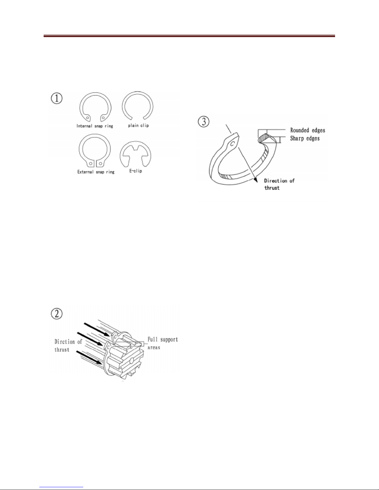
Snap Rings and E-clips
Snap rings (Figure 1) are circular-shaped
metal retaining clips.
They secure parts in place on parts such
as shafts. External type snap rings are
used to hold items on shafts. Internal type
snap rings secure parts within housing
bores. In some applications, in addition to
securing the component(s), snap rings of
varying thicknesses also determine
endplay. These are usually called
selective snap rings. The two basic types
of snap rings are machined and stamped
snap rings. Machined snap rings
(Figure2) can be installed in either
direction.
Because both faces have sharp edges.
Stamped snap rings (Figure3) are
manufactured with a sharp and a round
edge. When installing a stamped snap ring
in a thrust application, install the sharp
edge facing away from the part producing
the thrust.
E-clips are used when it is not practical to
use a snap ring. Remove E-clips with a flat
blade screwdriver by prying between the
shaft and E-clip. To install an E-clip, center
it over the shaft groove and push or tap it
into place. Observe the following when
installing snap rings:
1. Remove and install snap rings with
snap rings pliers. Refer to Basic
Tools in this chapter.
2. In some applications, it may be
necessary to replace snap rings after
removing them.
3. Compress or expand snap rings only
enough to install them. If overly
expanded, they lose their
retaining ability.
4. After installing a snap ring. Make
sure it seats completely.
5. Wear eye protection when removing
and installing snap rings
1-10

SHOP SIPPLIES
Lubricants and Fluids
Periodic lubrication helps ensure a long
service life for any type of equipment.
Using the correct type of lubricant is as
important as performing the lubrication
service. Although in an emergency the
wrong type is better than not using one,
The following section describes the
types of lubricants most often required.
Make sure to follow the manufacturer’s
recommendations for lubricant types.
Engine oils
Engine oil for the four-stroke UTV
engine is classified by two standards:
the American Petroleum Institute (API)
service classification and the Society of
Automotive Engineers (SAE) viscosity
rating Standard classification. The API
and SAE information is on all oil
container labels. Two letters indicate
the API service classification. The
number or sequence of numbers and
letters (10W-40SG for example) is the
oil’s viscosity rating. The API service
classification and the SAE viscosity
index are not indications of the oils
quality.
In the API service classification
standards, the first letter in the
classification S indicates that the oil is
for gasoline engines. The second letter
indicates the standard the oil satisfies.
The classifications are: MA (high friction
applications) and MB( low frication
applications).
General
Note:
Refer to Engine Oil and Filter in Chapter
Three for further information on API,
SAE classifications.
Always use an oil with a classification
recommended by the manufacturer, Using
an oil with a different classification can
cause engine damage. Viscosity is an
indication of the oil’s thickness. Thin oils
have a lower number while thick oil have a
higher number. Engine oils fall into the 5-to
50-weight range for single-grade oils. Most
manufactures recommend multi-grade oil.
These oils perform efficiently across a wide
range of operating conditions. Multi-grade
oils are identified by a W after the first
number, which indicates the lowtemperature viscosity. Engine oils are most
commonly mineral (petroleum) based, but
synthetic and semi-synthetic types are used
more frequently. When selecting engine oil,
follow the manufacturer’s recommendation
for type, classification and viscosity.
Greases
Grease is lubricating oil with thickening
agents added to it. The National Lubricating
GreaseInstitute (NLGI) grades grease.
Grades range from No.000 to No.6, with
No.6 being the thickest. Typical
multipurpose grease is NLGI No.2. For
specific applications, manufacturers may
recommend a water-resistant type grease
or one with an additive such as
molybdenum disulfide (MoS2).
Brake fluid
Brake fluid is the hydraulic fluid used to
transmit hydraulic pressure (force) to the
wheel brakes. Brake fluid is classified by
the Department of Transportation (DOT).
1-11

Current designations for brake fluid are
DOT 3, DOT 4 and DOT 5, this
classification appears on the fluid
container. Each type of brake fluid has
its own definite characteristics. Do not
intermix different types of brake fluid as
this may cause brake system failure.
DOT 5 brake fluid is silicone based.
DOT 5 is not compatible with other
brake fluids may cause brake system
failure. When adding brake fluid, only
use the fluid recommended by the
manufacturer. Brake fluid will damage
any plastic, painted or plated surface it
contacts. Use extreme care when
working with brake fluid and remove
any spills immediately with soap and
water. Hydraulic brake systems require
clean and moisture free brake fluid.
Never reuse brake fluid.
Keep containers and reservoirs properly
sealed.
Warning:
Never put a mineral-based
(Petroleum) oil into the brake
system. Mineral oil causes rubber
parts in the system to deteriorate
causing complete brake failure.
Coolant
Coolant is a mixture of water and
antifreeze used to dissipate engine
heat. Ethylene glycol is the most
common form of antifreeze. Check the
UTV Manufacturer’s recommendations
when selecting antifreeze. Most require
one specifically designed for aluminum
engines. These types of antifreeze
have additives that inhibit corrosion.
Only mix antifreeze with distilled water.
Impurities in tap water may damage
internal cooling system passages.
General
Cleaners, Degreasers and
Solvents
Many chemicals are available to remove oil,
grease and other residue from the UTV.
Before using cleaning solvents, consider
how they will be used and disposed of,
particularly if they are not water-soluble.
Local ordinances may restrict types of
cleaning chemicals. Refer to Safer in this
chapter. Use brake parts cleaner to clean
brake system components. Brake parts
cleaner leaves no residue. Electrical
contact cleaner is a powerful solvent used
to remove fuel deposits and varnish from
fuel system components. Use this cleaner
carefully, as it may damage finishes.
Most solvents are designed to be used with
a parts washing cabinet for individual
component cleaning. For safety, use only
nonflammable or high flash point solvents.
Gasket Sealant
Sealant is used in combination with a
gasket or seal. In other applications, such
as between crankcase halves, only a
sealant is used. Follow the manufacturer’s
recommendation when using a sealant.
Use extreme care when choosing a
sealant, or a different sealant based on its
resistance to heat, various fluids and its
sealing capabilities.
Gasket Remover
Aerosol gaskets remover can help remove
stubborn gasket. This product can speed
up the removal process and prevent
damage to the mating surface that may be
caused by using a scraping tool. Most of
these types of products are very caustic.
Follow the gasket remover manufacturer’s
instructions for use.
1-12

Thread locking Compound
A thread locking compound is a fluid
applied to the threads of fasteners.
After tightening the fastener, the fluid
dries and becomes a solid filler
between the threads. This makes it
difficult for the fastener to work loose
from vibration or expansion and
contraction. Use thread locking
compound sparingly. Excess fluid can
run into adjoining parts.
Caution:
Thread locking compounds are
anaerobic and will stress, crack and
attack most plastics. Use caution
when using these products in areas
where there are plastic components.
Thread locking compounds are
available in a wide range of compounds
for various strengths, temperature and
repair applications. Follow the
manufacturer’s recommendations
regarding compound selection.
BASIC TOOLS
Most of the procedures in this manual
can be carried out with basic hand tools
and test equipment familiar to the home
mechanic. Always use the correct tools
for the job. Keep tools organized and
clean. Store them in a tool chest with
related tools organized together.
Quality tools are essential. The best are
constructed of high-strength alloy steel.
These tools are light, easy to use and
resistant to wear. Their working surface
is devoid of sharp edges and carefully
polished. They have an easy-to-clean
finish and are comfortable to use.
Quality tools are a good investment.
General
Some of the procedures in this manual
specify special tools. In many cases the
tool is illustrated in use. Those with a large
tool kit may be able to perform procedures.
However, in some cases, the specialized
equipment or expertise may make it
impractical for the home mechanic to
attempt the procedure. When necessary,
such operations are recommended to have
a dealership or specialist perform the task.
It may be less expensive to have a
professional perform these jobs, especially
when considering the cost of equipment.
When purchasing tools to perform the
procedures covered in this manual,
consider the tool’s potential frequency of
use. If a tool kit is just now being started,
consider purchasing a basic tool set from a
quality tool supplier that can offer
substantial savings when complicated,
specialized tools need to be added.
Screwdrivers
Screwdrivers of various lengths and types
are mandatory for the simplest tool kit. The
two basic types are the slotted tip (flat
blade) and the Phillips tip. These are
available in sets that often include an
assortment of tip size and shaft lengths.
As with all tools, use a screwdriver
designed for the job. Make sure of the size
of the fastener. Use them only for driving
screws. Never use a screwdriver for prying
or chiseling metal. Repair or replace
worn or damaged screwdrivers. A worn tip
may damage the fastener, making it difficult
to remove. Phillips-head screws are often
damaged by incorrectly fitting screwdrivers.
Quality Phillips screwdrivers are
manufactured with their crosshead tip
machined to Phillips Screw Company
specifications.
1-13
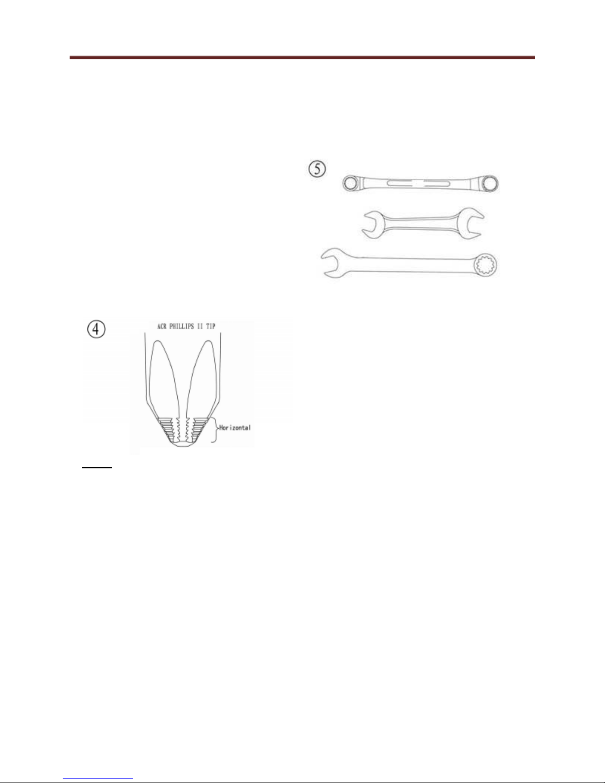
Poor quality or damaged Phillips
screwdrivers can back out (cam out)
and round over the screw head. In
addition. Weak or soft screw materials
can make removal difficult. The best
type of screwdriver to use on a Phillips
screw is the ACR Phillips II screwdriver,
patented by the horizontal anti-cam out
ribs found on the driving faces or flutes
of the screwdriver’s tip (figure 4).
ACR Phillips II screwdrivers were
designed as part of a manufacturing
drive system to be used with ACR
Phillips II screws. Many tool companies
offer ACR Phillips II screwdrivers in
different Tip size and interchangeable
bits to fit screwdriver bit holders
.
Note:
Another way to prevent cam out and
to increase the grip of a Phillips
screwdriver is to apply valve
grinding compound or permute
screw & socket Gripper onto the
screwdriver tip. After loosening or
tightening the screw, clean the screw
recess to prevent engine oil
contamination.
General
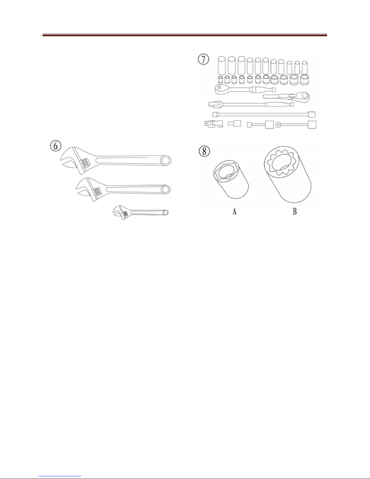
Wrenches
Open-end, box-end and combination
wrenches (figure 5) are available in a
variety of types and sizes.
The number stamped on the wrench refers
to the distance of the fastener head.
The box-end wrench is an excellent tool
because it grips the fastener on all sides.
This reduces the chance of the tool
slipping. The box-end wrench is designed
with either a 6 or 12-point opening. For
stubborn or damaged fasteners, the 6-point
provides superior holding because it
contacts the fastener across a wider area at
all six edges. For general use, the 12-point
works well. It allows the wrench to be
removed and reinstalled without moving the
handle over such a wide area. An open-end
wrench is fast and works best in areas with
limited overhead access. It contacts the
fastener at only two points and is subject to
slipping if under heavy force, or if the tool or
fastener is worn. A box-end wrench is
preferred in most instances, especially
when braking loose and applying the final
tightness to a fastener. The combination
wrench has a box-end on one end and an
open-end on the other. This combination
makes it a convenient tool.
1-14
General
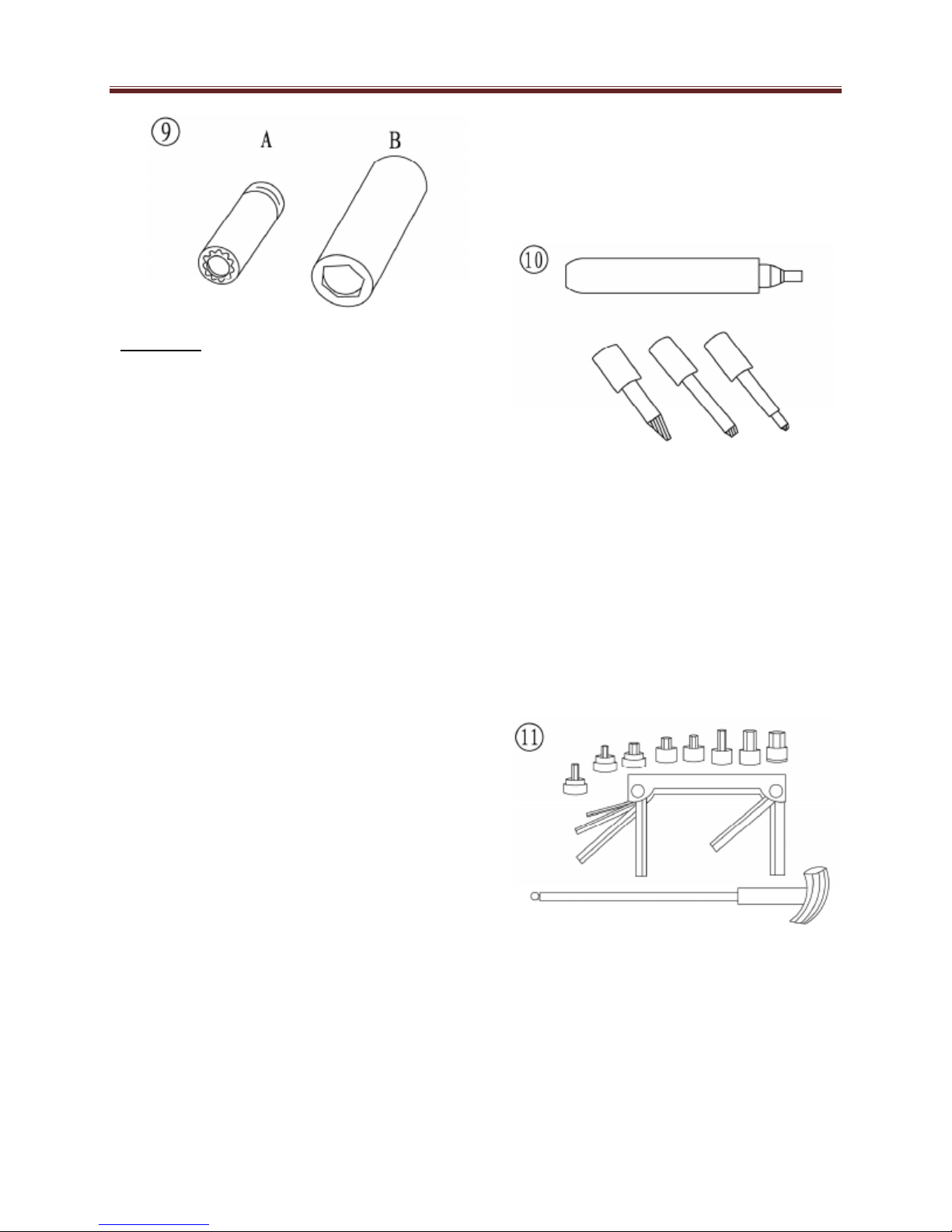
Adjustable Wrenches
An adjustable wrench or Crescent wrench
(Figure 6) can fit nearly any nut or bolt
head that has clear access around its entire
perimeter. An adjustable wrench is best
used as a backup wrench to keep a large
nut or bolt from turning while the other end
is being loosened or tightened with a boxend or socket wrench.
Adjustable wrenches contact the fastener
at only two points, which makes them more
subject to slipping off the fastener. Because
one jaw is adjustable and may become
loose, this shortcoming is aggravated.
Make certain the solid jaw is the one
transmitting the force.
Socket Wrenches, Ratchets and
Handles
Sockets that attach to a ratchet handle
(Figure 7) are available with 6-point or 12point openings (Figure8) and different drive
sizes.
The drive size indicates the size of the
square hole that accepts the ratchet
handle. The number stamped on the
socket is the size of the fastener head.
As with wrenches, a 6-point provides
superior-holding ability. While a 12-point
socket needs to be moved only half as
much to reposition it on the fastener.
Sockets are designated for either hand
or impact use. Impact sockets are made
of thicker material for more durability.
Compare the size and wall thickness
of a 19-mmhand socket (A, Figure 9)
and the 19-mm impact socket (B). Use
impact sockets when using an impact
driver or air tools. Use hand sockets with
hand-driven attachments.
1-15
General
Warning:
Do not use hand sockets with air or
impact tools because they may shatter
and cause injury. Always wear eye
protection when using impact or air tools.
Various handles are available for sockets.
Use the speed handle for fast operation.
Flexible ratchet heads in varying length allow
the socket to be turned with varying force
and at odd angles. Extension bars allow the
socket setup to reach difficult areas. The
ratchet is the most versatile. It allows the
user to install or remove the nut without
removing the socket. Sockets combined with
any number of drivers make them
undoubtedly the fastest, safest and most
convenient tool for fastener removal and
installation.
Impact Drivers
An impact driver provides extra force for
removing fasteners by converting the impact
of a hammer into a turning motion.
This makes it possible to remove stubborn
fasteners without damaging them.
Impact drivers and interchangeable bits
(Figure 10) are available from most
tool suppliers. When using a socket
with an impact driver. Make sure the
socket is designed for impact use.
Allen Wrenches
Use Allen or setscrew wrenches
(Figure 11) on fasteners with
hexagonal recesses in the fastener
head. These wrenches are available in
L-shaped bar, socket and T-handle
types. A metric set is required when
working on most UTV’s. Allen bolts are
sometimes called socket bolts.
1-16
General
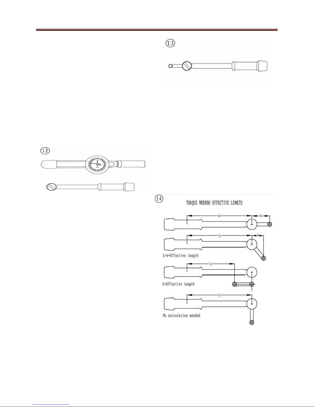
Torque Wrenches
Use a torque wrench with a socket,
torque adapter or similar extension to
tighten a fastener to a measured torque.
Torque wrenches come in several drive
sizes (1/4, 3/8, 1/2 and 3/4) and have
various methods of reading the torque
value. The drive size indicates the size
of the square drive that accepts the
socket, adapter or extension. Common
methods of reading the torque value are
the deflecting beam, the dial indicator
and the audible click (Figure 12).
When choosing a torque wrench,
consider the torque range, drive size and
accuracy. The torque specifications in
this manual provide an indication of the
range required. A torque wrench is a
precision tool that must be properly
cared for to remain accurate. Store
torque wrenches unloaded in cases or
separate padded drawers within a
toolbox. Follow the manufacturer’s
instructions for their care and calibration.
Torque Adapters
Torque adapters or extensions extend or
reduce the reach of a torque wrench.
The torque adapter shown in (Figure 13)
is used to tighten a fastener that cannot
be reached because of the size of the
torque wrench head, drive, and socket.
If a torque adapter changes the effective lever
length (Figure 14), the torque reading on the
wrench will not equal the actual torque
applied to the fastener. It is necessary to
recalibrate the torque setting on the wrench to
compensate for the change of lever length.
When using a torque adapter at a right angle
to the drive head, calibration is not required,
because the effective length has not
changed. To recalculate a torque reading
when using a torque adapter, use the
following formula and refer to Figure 14:
1-17
General
TW = TA×L
L+A
TW is the torque setting or dial reading
on the wrench. TA is the torque
specification and the actual amount of
torque that is applied to the fastener. A
is the amount that the adapter increases
(or in some cases reduces) the effective
lever length as measured along the
centerline of the torque wrench. L is the
lever length of the wrench as measured
from the center of the drive to the center
of the grip. The effective length is the
sum of L and A.
Example:
TA=20 ft.-lb.
A=3in.
L=14in.
TW=20×14=280=16.5 ft. - lb.
14+3 = 17
In this example, the torque wrench
would be set to the recalculated torque
value (TW = 16.5 ft. –lb). When using a
beam-type wrench, tighten the fastener
until the pointer aligns with 16.5 ft. –lb. In
this example, although the torque
wrench is pre set to 16.5 ft. –lb., the
actual torque is 20 ft. –lb.
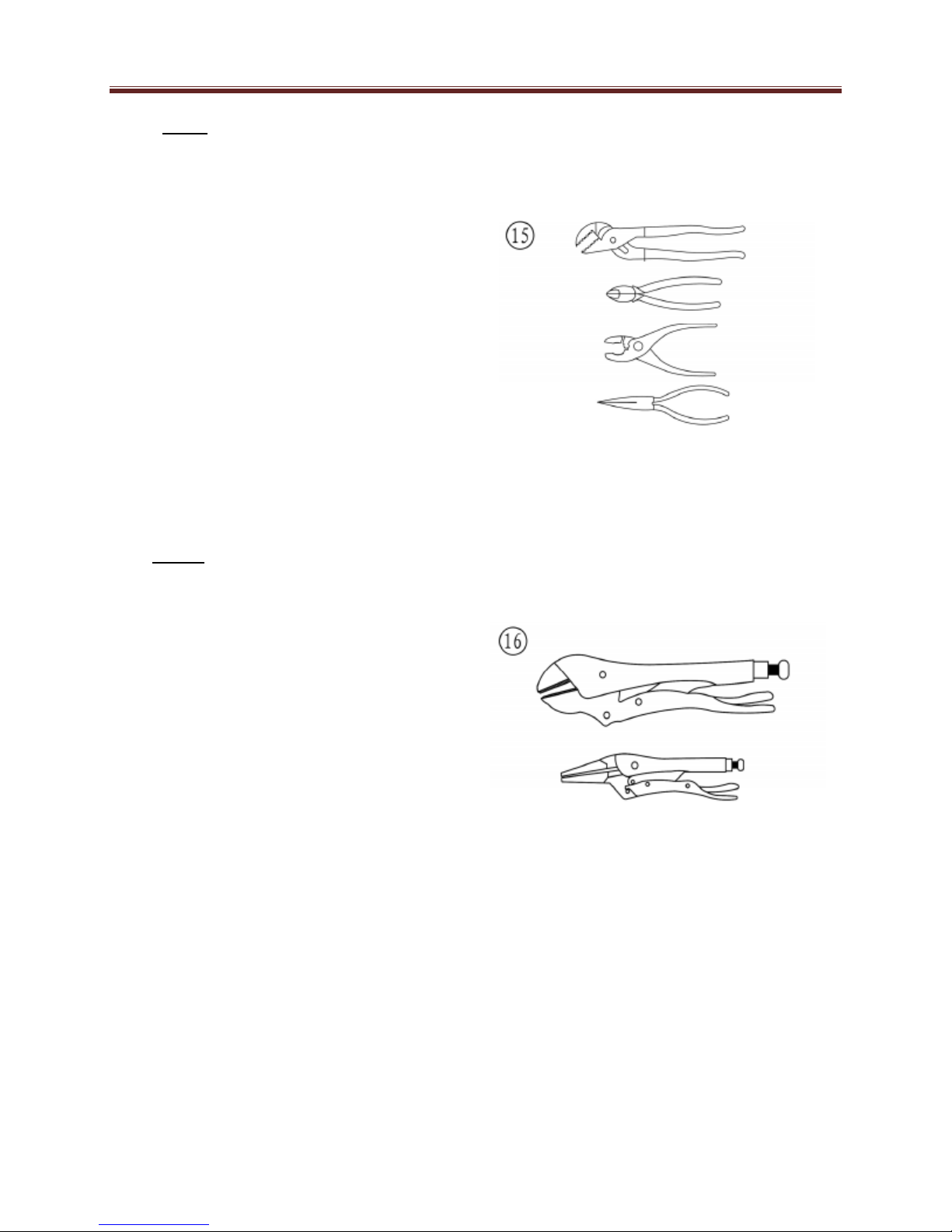
Pliers
Pliers come in a wide range of types and
sizes. Pliers are useful for holding,
cutting, bending, and crimping. Do not
use them to turn fasteners. Figure 15
shows several types of useful pliers.
Each design has a specialized function.
Slip-joint pliers are general – purpose
pliers used for gripping and bending.
Diagonal cutting pliers are needed to cut wire
and can be used to remove cotter pins. Use
needle nose pliers to hold or bend small
objects.
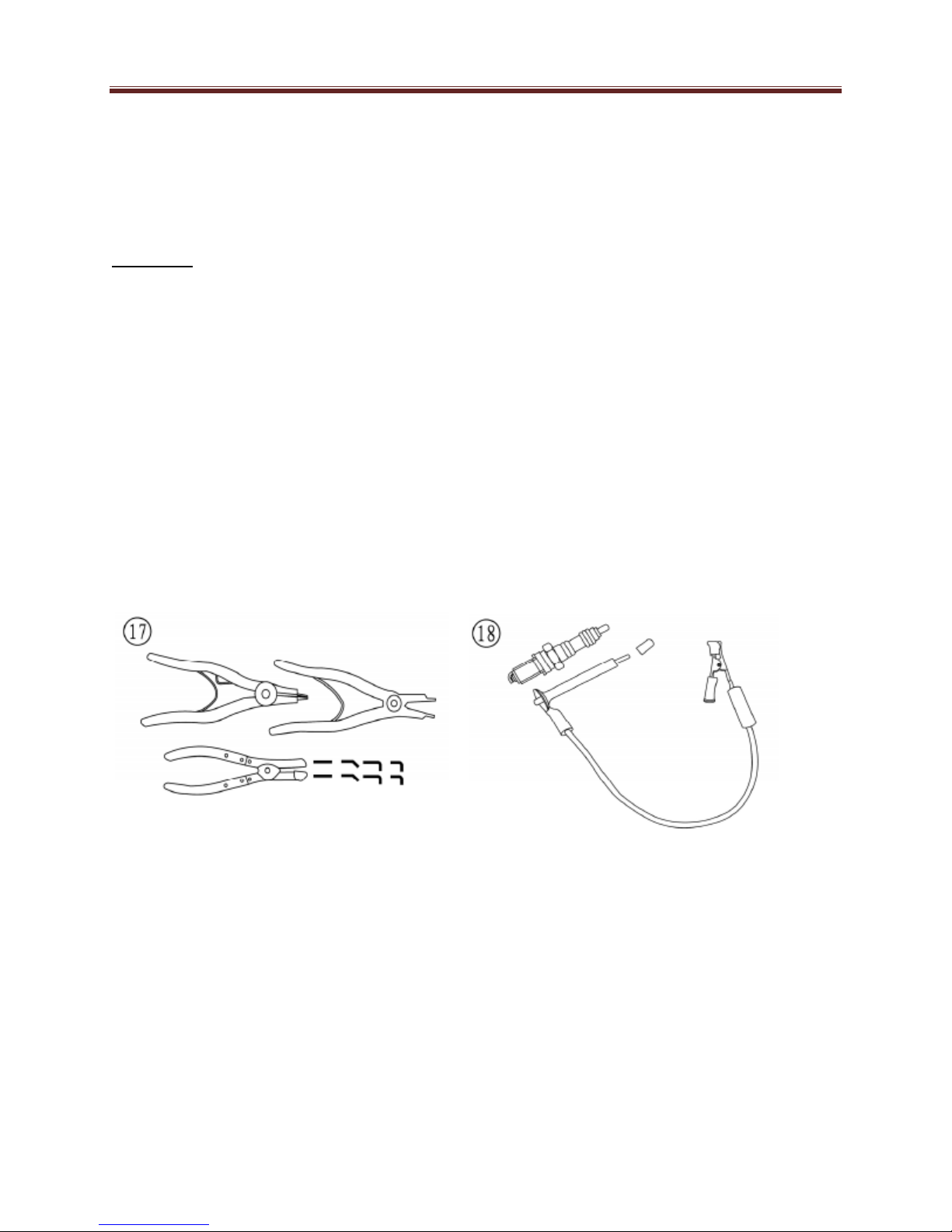
Locking pliers (Figure 16), sometimes called
Vise-Grips, are used to hold objects very
tightly. They have many uses ranging from
holding two parts together, to gripping the end
of a broken stud. Use caution when using
locking pliers, as the sharp jaws will damage
the objects they hold.
1-18
General
Snap Ring Pliers
Snap ring pliers are specialized pliers
with tips that fit into the ends of snap
rings to remove and install them.
Warning:
Snap rings can slip and fly off when
removing and installing them. Also,
the snap ring pliers tips may break.
Always wear eye protection when
using snap ring pliers.
Snap ring pliers (Figure 17) are
available with a fixed action (either
internal or external ) or convertible (one
tool works on both internal and external
snap rings). They may have fixed tips or
interchangeable ones of various sizes
and angles. For general use, select a
convertible type snap ring plier with
interchangeable tips (Figure 17).
Use soft-faced hammers when a metal object
must be/struck without damaging it. Never
use a metal-faced hammer on engine and
suspension components because damage
occurs in most cases. Always wear eye
protection when using hammers. Make sure
the hammer face is in good condition and the
handle is not cracked. Select the correct
hammer for the job and make sure to strike
the object squarely. Do not use the handle or
the side of the hammer to strike an object.
Ignition Grounding Tool
Some test procedures require turning the
engine over without starting it. To prevent
damage to the ignition system from excessive
resistance or the possibility of fuel vapor
being ignited by an open
spark, remove the spark plug cap and ground
it directly to a good engine ground with the
tool shown in (Figure 18).
Hammers
Various types of hammers are available
to fit a number of applications. Use a
ball-peen hammer to strike another tool,
such as a punch or chisel.
Make the tool shown from a No.6 screw and
nut, two washers, length of tubing, alligator
clip, an electrical eyelet and a length of wire.
1-19

General
PRECISION MEASURING
TOOLS
The ability to accurately measure
components is essential to perform
many of the procedures described in this
manual. Equipment is manufactured to
close tolerances, and obtaining
consistently accurate measurements is
essential to determine which
components require replacement or
further service. Each type of measuring
instrument is designed to measure a
dimension with a certain degree of
accuracy and within a certain range.
When selecting the measuring tool,
make sure it is applicable to the task. As
with all tools, measuring tools provide
the best results if cared for properly.
Improper use can damage the tool and
cause inaccurate results. If any
measurement is questionable, verify the
Measurement, using another tool. A
standard gauge is usually provided with
micrometers to check accuracy and
calibrate the tool if necessary. Precision
measurements can vary according to the
experience of the person performing the
procedure. Accurate results are only
possible if the mechanic possesses a
feel for using the tool. Heavy-handed
use of measuring tools produces less
accurate results. Hold the tool gently by
the fingertips to easily feel the point at
which the tool contacts the object. This
feel for the equipment produces more
accurate measurements and reduces
the risk of damaging the tool or
component. Refer to the following
sections for specific measuring tools.
Feeler Gauge
Use feeler or thickness gauges (Figure19) for
measuring the distance between two
surfaces.
A feeler gauge set consists of an assortment
of steel strips of graduated thickness. Each
blade is marked with its thickness. Blades can
be of various lengths and angles for different
procedures. A common use for a feeler gauge
is to measure valve clearance. Use wire
(round) type gauges to measure spark plug
gap.
Calipers
Calipers (Figure 20) are excellent tools for
obtaining inside, outside and depth
measurements.
1-20
General
Although not as precise as a
micrometer, they allow reasonable
precision, typically to within 0.05 mm
(0.001 in.). Most calipers have a range
up to 150 mm (6 in). Calipers are
available in dial, venire or digital
versions. Dial calipers have a dial
readout that provides convenient
reading. Venire calipers have marked
scales that must be compared to
determine the measurement.
The digital caliper uses a liquid-crystal
display (LCD) to show the measurement.
Properly maintain the measuring
surfaces of the caliper. There must not
be any dirt or burrs between the tool and
the object being measured. Never force
the caliper to close around an object.
Close the caliper around the highest
point so it can be removed with a slight
drag. Some calipers require calibration.
Always refer to the manufacturer’s
instructions when using a new or
unfamiliar caliper. To read a Vernire
Caliper refer to Figure 21.
The fixed scale is marked in l-mm
increments. Ten individual lines on the
fixed scale equal 1 cm. The movable
scale is marked in 0.05 mm (hundredth)
increments. To obtain a reading,
establish the first number by the location
of the 0 line on the movable scale in
relation to the first line to the left on the
fixed scale. In this example, the number is 10
mm. To determine the next number, note
which of the lines on the movable scale align
with a mark on the fixed scale. A number of
lines will seem close, but only one will align
exactly. In this case, 0.50 mm is the reading
to add to the first number. Adding 10 mm and
0.50 mm equals a measurement of 10.50mm.
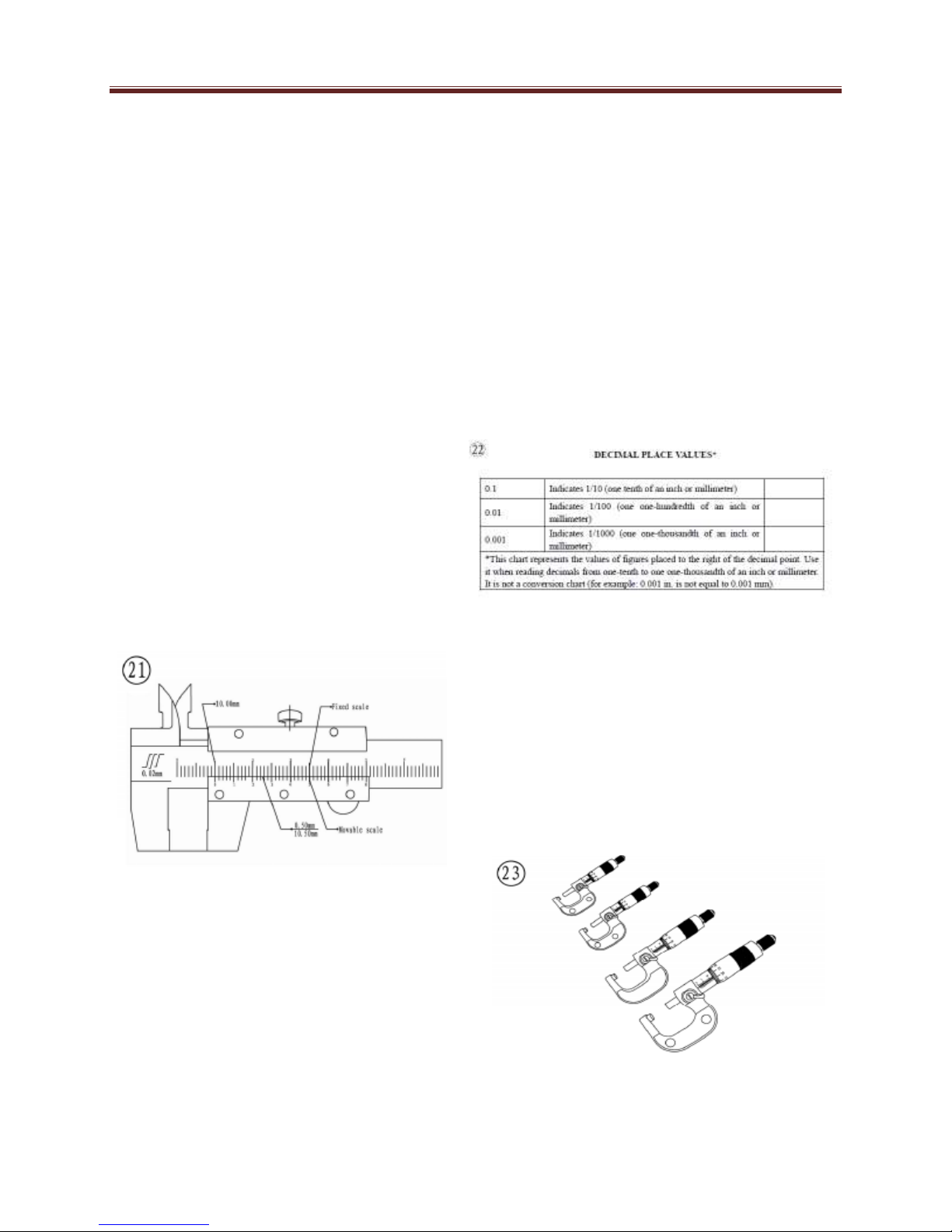
Micrometers
A micrometer is an instrument designed for
linear measurement using the decimal
divisions of the inch or meter (Figure 22).
While there are many types and styles of
micrometers, most of the procedures in this
manual call for an outside micrometer. Use
the outside micrometer to measure the
outside diameter of round parts and the
thickness of materials. A micrometer’s size
indicates the minimum and maximum size of
a part that it can measure. The usual sizes
(Figure 23) are 0-25mm (0-1 in), 25-50 mm
(1-2 in), 50-75 mm (2-3 in) and 75-100 mm
(3-4 in).
1-21

General
Micrometers that cover a wider range of
measurements are available. These use
a large frame with interchangeable
anvils of various lengths. This type of
micrometer offers a cost savings, but its
overall size may make it less convenient.
When reading a micrometer, numbers
are taken from different scales and
added together. The following sections
describe how to adjust, care for and read
the measurements of various types of
outside micrometers. For accurate
results, properly maintain the measuring
surfaces of the micrometer. There
cannot be any dirt or burrs between the
tool and the measured object. Never
force the micrometer to close around an
object. Close the micrometer around the
highest point so it can be removed with a
slight drag.
Adjustment
Before using a micrometer, check its
adjustment as follows:
1. Clean the anvil and spindle faces.
2. To check a 0-1 in. or 0-25 mm
micrometer:
• Turn the thimble until the spindle
contacts the anvil. If the
micrometer has a ratchet stop,
use it to ensure that the proper
amount of pressure is applied.
• If the adjustment is correct, the 0
mark on the thimble will align
exactly with the 0 mark on the
sleeve line. If the marks do not
align, the micrometer is out of
adjustment. Follow the
manufacturer’s instructions to
adjust the micrometer.
3. To check a micrometer larger than 1
in. or 25mm use the standard gauge
Supplied by the manufacturer. A
standard gauge is a steel block, disc or
rod that is machined to an exact size.
• Place the standard gauge between the
spindle and anvil, and measure its
outside diameter or length. If the
micrometer has a ratchet stop, use it to
ensure that the proper amount of
pressure is applied.
• If the adjustment is correct, the 0 mark
on the thimble will align exactly with
the 0 mark on the sleeve line. If the
marks do not align, the micrometer is
out of adjustment.
• Follow the manufacturer’s instructions
to adjust the micrometer.
Care
Micrometers are precision instruments. They
must be used and maintained with great care.
Note the following:
1. Store micrometers in protective cases
or separate padded drawers in a tool
box.
2. When in storage, make sure the
spindle and anvil faces do not contact
each other or another object. If they
do, temperature changes and
corrosion may damage the contact
faces.
3. Do not clean a micrometer with
compressed air. Dirt forced into the
tool will cause wear.
1-22
General
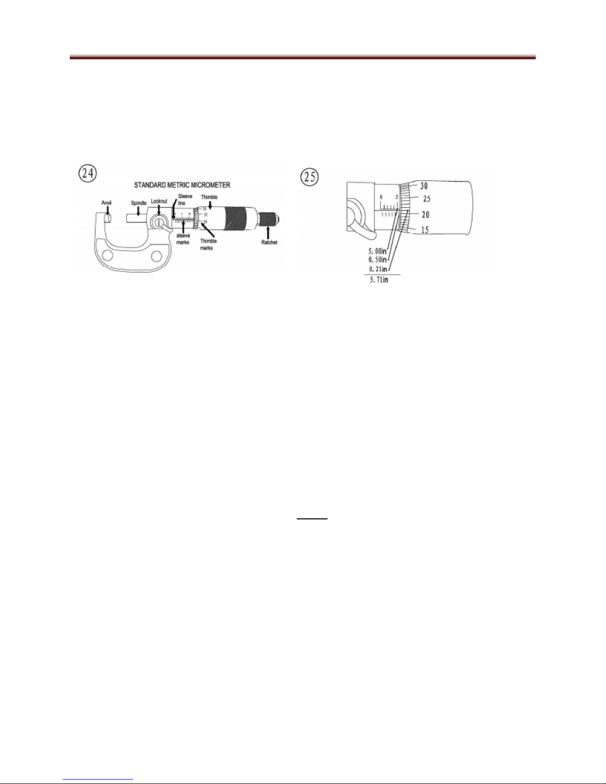
Metric micrometer
The standard metric micrometer (Figure
24) is accurate to one one-hundredth of
a millimeter (0.01mm).
The sleeve line is graduated in millimeter
and
half millimeter increments. The marks on
the upper half of the sleeve line equal
1.00 mm. Each fifth mark above the
sleeve line is identified with a number.
The number sequence depends on the
size of the micrometer. A 0-25 mm
micrometer, for
example, will have sleeve marks
numbered 0
through 25 in 5 mm increments. This
numbering sequence continues with
larger micrometers. On all metric
micrometers, each mark on the lower
half of the sleeve equals 0.50 mm. The
tapered end of the thimble has 50 lines
marked around it. Each mark equals
0.01 mm. One complete turn of the
thimble aligns its 0 mark with the first
line on the lower half of the sleeve line or
0.50mm.
When reading a metric micrometer, add the
number of millimeters and half-millimeters on
the sleeve line to the number of one one
hundredth millimeters on the thimble. Perform
the following steps while referring to Figure
25.
1. Read the upper half of the sleeve line
and count the number of lines visible.
Each upper line equals 1mm.
2. See if the half –millimeter line is
visible on the lower sleeve line. If so,
add 0.50mm to the reading in Step 1.
3. Read the thimble mark that aligns with
the sleeve line. Each thimble mark
equals 0.01mm.
4. Add the readings from Steps 1-3.
Note:
If a thimble mark does not align exactly
with the sleeve line. Estimate the amount
between the lines. For accurate readings
in two-thousandths of a millimeter
(0.002mm), use a metric vernier
micrometer.
1-23
General
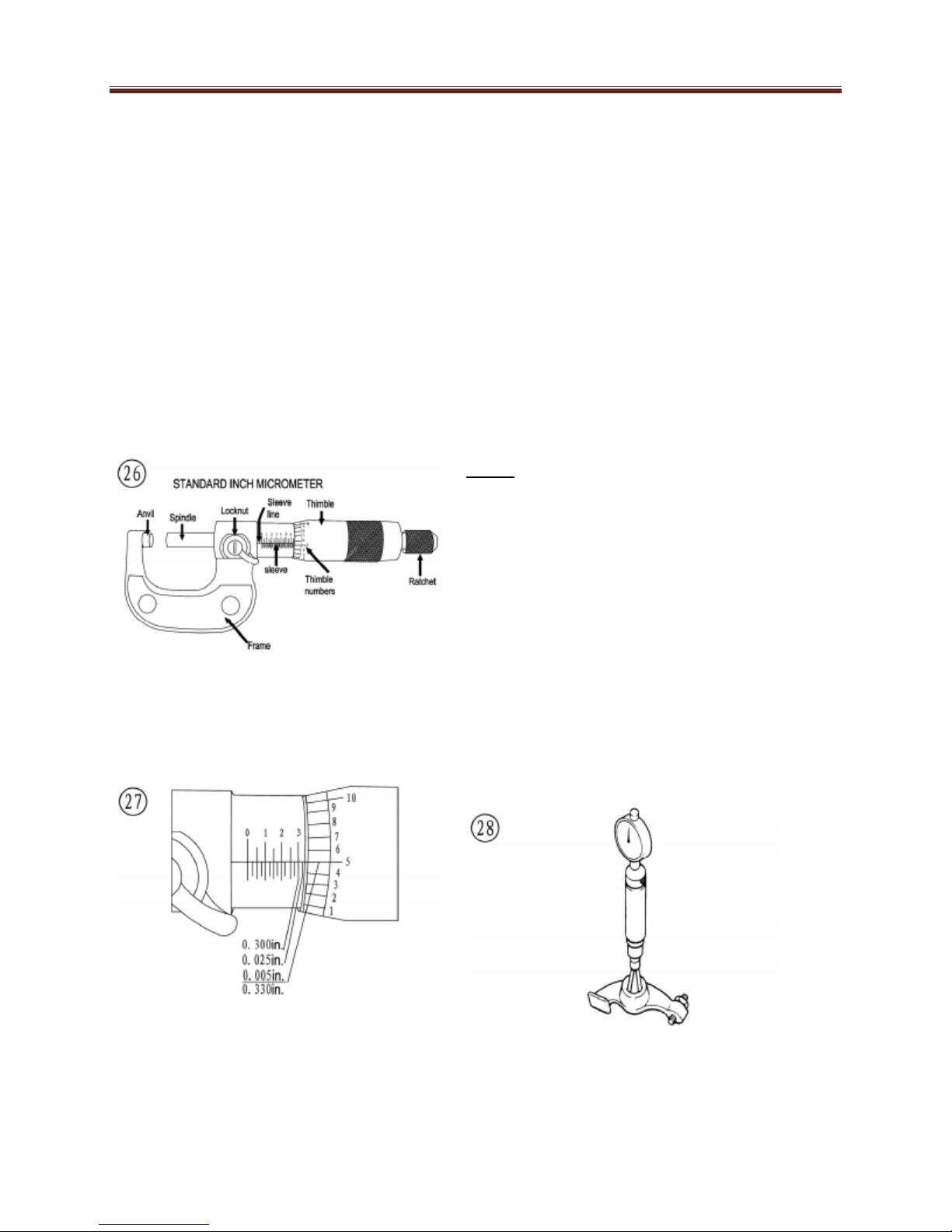
Standard Inch Micrometer
The standard inch micrometer (Figure
26) is
accurate to one-thousandth of an inch or
0.001. The sleeve is marked in 0.025 in.
increments. Every fourth sleeve mark is
numbered 1,2,3,4,5,6,7,8,9. These
numbers indicate 0.100, 0.200, 0.300,
and so on.
The tapered end of the thimble has 25
lines marked around it. Each mark
equals 0.001 in. One complete turn of
the thimble will align its zero mark with
the first mark on the sleeve or 0.025 in.
To read a standard inch micrometer,
perform the following steps and refer to
Figure 27.
1. Read the sleeve and find the largest
number visible. Each sleeve number
equals 0.100 in.
2. Count the number of lines between
the numbered sleeve mark and the
edge of the thimble. Each sleeve mark
equals 0.025 in.
3. Read the thimble mark that aligns with
the sleeve line. Each thimble mark
equals 0.01 in.
4. Add the readings from Steps 1-3.
Note:
If a thimble mark does not align exactly
with the sleeve line, estimate the amount
between the lines. For accurate readings
in ten-thousandths of an inch (0.0001 in),
use a vernier inch micrometer.
Telescoping and Small Bore Gauges
Use telescoping gauges (Figure 28) and
small bore gauges (Figure 29) to measure
bores. Neither gauge has a scale for direct
readings. Use an outside micrometer to
determine the reading.
1-24
 Loading...