


Introduction HS164-4
INTRODUCTION
Congratulations on your purchase of the HS164-4. This Owner’s / Operator’s manual will
provide you information regarding safe operation, operational instructions, maintenance and
care. Fully understanding this manual and following all of the instructions herein will provide
the knowledge needed to have safe and enjoyable vehicle operation.
If you have any questions regarding the operation or maintenance of your UTV, please
Finland.
call Monkija Trail Park Oy at 0086-23-61020546 or go to Pajalantie 6a 37550, Lempaala,
IMPORTANT SAFETY MESSAGES
● READ THIS MANUAL CAREFULLY AND COMPLETELY BEFORE OPERATING YOUR UTV.
MAKE SURE YOU UNDERSTAND ALL INSTRUCTIONS.
● PAY CLOSE ATTENTION TO THE WARNING AND CAUTION LABELS ON THE UTV.
● NEVER OPERATE THE UTV WITHOUT PROPER TRAINING OR INSTRUCTIO N.
● THIS UTV SHOULD NOT BE RIDDEN BY ANYONE UNDER
16 YEARS OF AGE.
1-1
Introduction HS164-4
IMPORTANT MANUAL INFORMATION
FAILURE TO FOLLOW THE WARNINGS CONTAINED IN THIS MANUAL CAN RESULT IN SERIOUS
INJURY
OR DEATH.
notations:
The Safety Alert Symbol means ATTENTION!
the machine operator, bystander or a person inspecting or repairing the
machine.
to the machine.
NOTE: A NOTE provides key information to make procedures easier
Particularly important information is distinguished in this manual by the following
YOUR SAFETY IS INVOLVED!
Failure to follow WARNING instructions could result in severe injury or death to
A CAUTION indicates special precautions that must be taken to avoid damage
clearer.
1-2

Introduction HS164-4
IMPORTANT NOTICE
This vehicle is designed and manufactured for ON - ROAD use only.
This vehicle complies with all applicable ON - ROAD noise level and spark arrester laws and regulations
in effect at the time of manufacture.
Please check your local riding laws and regulations before operating this vehicle.
When the temperature is below -4°F (-20°C), park the vehicle in a place where the temperature is higher
than -4°F (-20°C). Start the vehicle after the vehicle has warmed up. Please see page 7-3 on the warming
up process.
Follow the proper parking procedures when the temperature is higher than 100°F (38°C): turn off the
engine; make sure the radiator fan is on for 3 minutes before turning off the power switch.
Starting the vehicle for the first time will take longer because the fuel will need reach the fuel injectors. To
start the vehicle the first time, hold the ignition key on at 5-second intervals. Allow the starter to rest 15
seconds between each start attempt.
1-3

Table of Contents
Subject
Introduction
Warnings Cautio ns an d
Notes
Important Notice
Table of Contents
Location Of Parts
Illustrated Contents
Safe Operation
Safety Instructions
Operation
Children safety instructions
Driving on a slope
Driving in harsh conditions
Driving at high speed
Instructions for carrier
Parking
Transportation
Maintenance
Warning and Caution Labels
Servicing of Vehicle
Specification table
Traveling speeds
Vehicle limitations
Pre-Operation
Operating the Engine
Engine and other check
lamps
Stopping the engine
Operating new vehicle
Seat belt
Head light switch
Emergency light switch
Turn Signal light switch
Brake Pedal
Gear shift lever
Accelerator pedal
Stopping
Fuel Gauge
Coolant temperature gauge
Speedometer
Winch Mount Plate
Transporting vehicle
Service intervals
Periodic Service
Hood
Operator’s Seat
The Cargo Bed
Shock Adjustment
Jack-up point
Coolant Level
radiator screen
Introduction HS164-4
Page
1-1
1-2
1-3
1-4
1-5
1-6
2-1
2-2
2-2
2-2
2-2
2-3
2-3
2-3
2-3
2-3
2-4
3-1
4-1
5-1
5-2
5-3
6-1
7-1
7-2
7-3
8-1
8-1
8-2
8-2
8-2
8-3
8-3
8-4
8-5
8-5
8-5
8-6
9-1
9-1
9-1
10-1
10-1
10-1
10-2
10-2
10-3
10-4
10-5
Subject
brake fluid level
brake pedal
parking brake
Greasing
engine start
Wheel bolt
Evacuator valve
Battery condition
Battery charging
Direction for storage
Adjusting toe-in
Adjusting procedures
Cleaning Muffl er
Changing engine oil
Replacing engine oil
filter
Checking brake pedal
Every 300 Hours
Changing brake fluid
Anti-freeze
Every 4 years
Vehicle storage
Removing the
vehicle from storage
Hitch Bar
Troubleshooting
Engine
Diagnostic Trouble
Code table
Battery Troubleshooting
Machine
Troubleshooting
Options
Emissions Warranty
Page
10-5
10-6
10-6
10-7
10-8
10-9
10-10
10-10
10-11
10-11
10-12
10-12
10-12
10-13
10-14
10-14
10-16
10-16
10-17
10-19
10-18
10-21
11-1
12-1
12-1
12-2
12-4
12-5
13-1
14
1-4
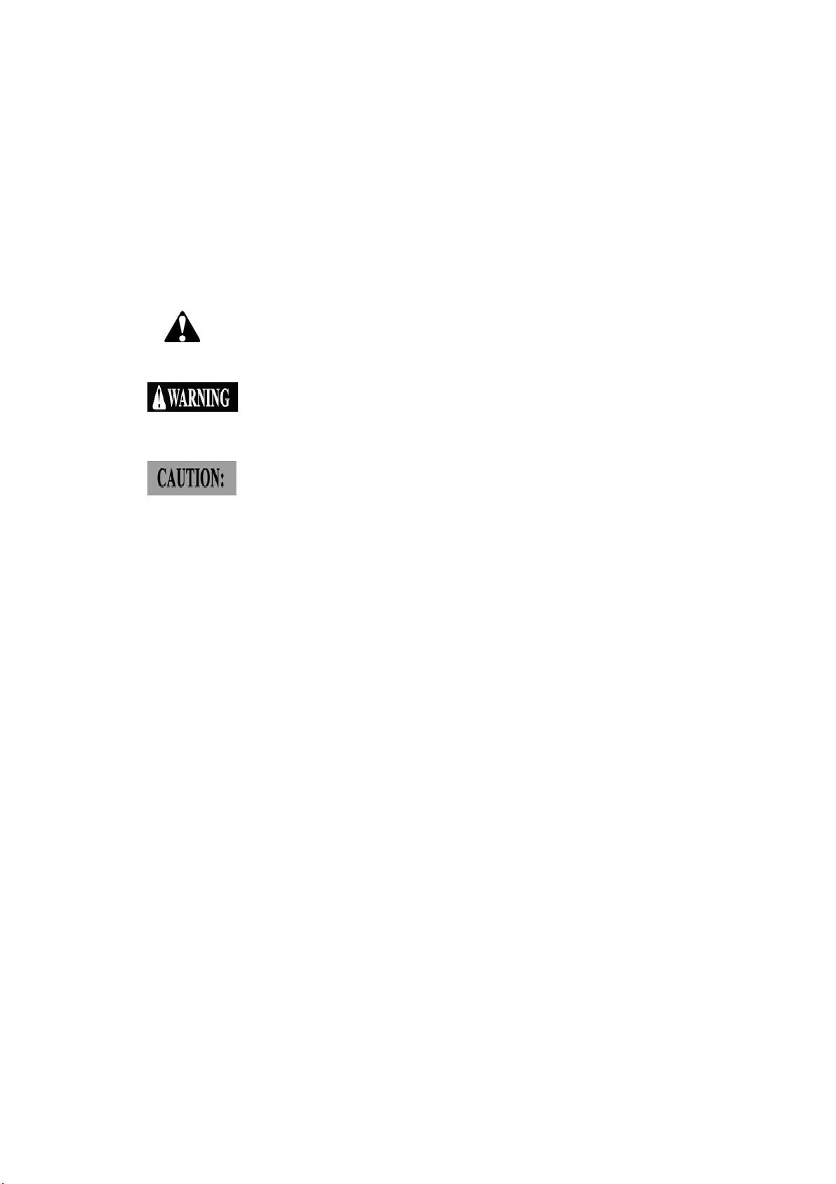
LOCATION OF PARTS
Introduction HS164-4
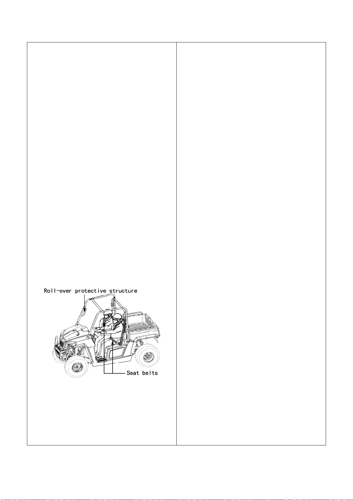
① Roll-over protective structure.
② Front hood
③ Headlights
④ Turn signal lights
⑤ Front bumper
1-5
Introduction HS164-4
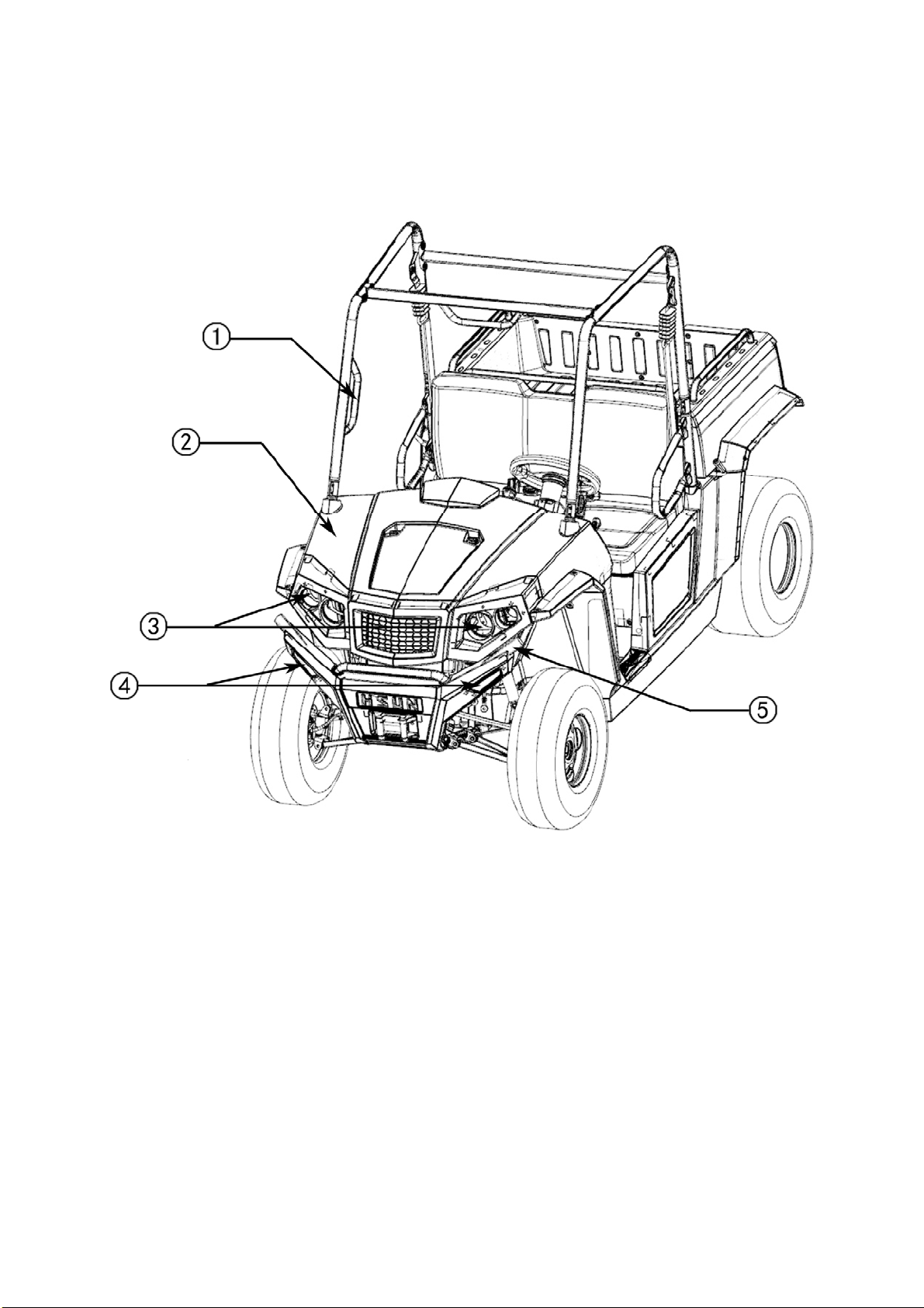
ILLUSTRATED CONTENTS
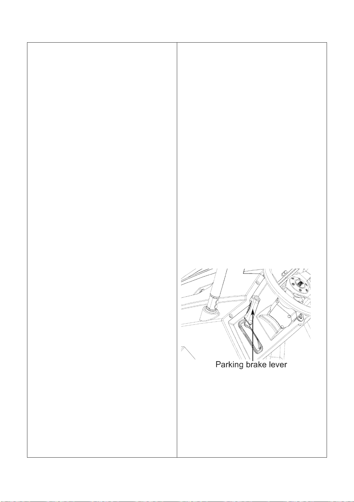
① Parking brake lever
② Steering wheel
③ Range gear shift lever
④ Accelerate pedal
⑤ Brake pedal
⑥ Fuel gauge
⑦ High beam / Low beam
⑧ Winch in /out
⑨ Turn signal lights
⑩ DC-socket
11
Emergency light switch
○
12
Reserve
○
1-6
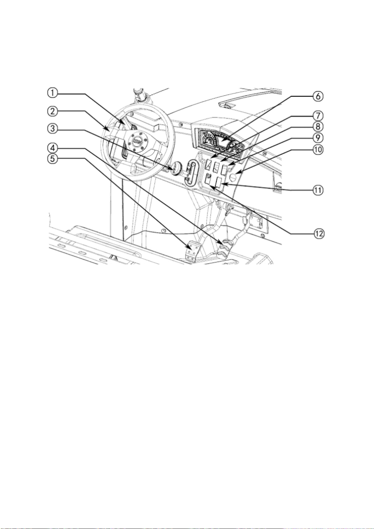
① Seat belts
② Seat
Introduction HS164-4
1-7
Safe Operation
All operators, including experienced vehicle
drivers or passengers, should carefully read and
fully understand this Users Manual, and operate
strictly as the manual states in order to achieve
the best performance and avoid accidents.
Others who will use you vehicle should be trained
how to operate the vehicle and be required to
read this manual before operation.
1. Safety Instructions:
1. Understand this vehicle by reading this
manual and understanding all the
components of the vehicle. Only start and
operate the vehicle after finishing reading
this manual.
2. Pay close attention to the warning and caution
labels on the vehicle.
3. Understand completely and learn to use the
safety devices (roll-over protective structure,
seat belts), and never change original safety
devices. If safety devices are damaged,
consult your local dealer for replacement.
Always use seat belts.
4. Do not wear loosen articles of clothing during
operation, as these can be drawn into moving
parts on the vehicle and could cause a severe
injury to occur.
5. Only a qualified driver should operate this
vehicle. Never operate after drinking, using
drugs or controlled products, or while fatigued.
6. Always perform the pre-operation checks as
following:
1) Check seat belt for wear or damage, if
necessary, replace it.
2) Check brakes, throttle, brake pedal and other
mechanical parts for proper operation. If you
discover any irregularities, replace related
parts as necessary. Periodically check the
fittings and fasteners.
3) Check engine oil level and engine coolant
level.
4) Check that the vehicle is equipped to handle
the surroundings.
5) Check and keep vehicle clean. Sludge,
grease and debris can cause a fire and
severe injury.
7. Passenger quantity and loading:
1) Only the driver and one passenger inside cab.
It is suggested that children under age of 5
not be allowed as a passenger.
2) Single-row vehicle’s loading limit is
505lbs(229KG). Reduce the loading weight
according to road conditions. Never exceed
the weight limits for operation.
Never allow unauthorized persons to repair
this vehicle. This may affect vehicle
performance and cause injury.
8. This vehicle is designed and manufactured for
off-road use only, so never drive on paved
roadways.
You should always wear protective equipment,
such as helmet, boots, eye protection, ear
2-1

Safe Operation
2. Operation
1. Start the engine only in an open ventilated
area. Carbon monoxide is colorless, odorless
and is emitted from the engine and can
cause death in areas with poor ventilation.
2. Never start the vehicle or operate the gear
selector unless seated in the driver’s seat.
3. Never start the engine until the select lever is
placed in “N” position and the brake is in the
brake position.
4. The driver and passenger shall always wear
their seatbelt while the vehicle is being
operated.
5. Operators of the vehicle should not wear
earphones.
6. Do not accelerate quickly when starting the
engine, especially driving on rough terrain as
3. Children safety instructions
Always watch children when they are around the
vehicle. Children like to imitate adults and this
could lead to an accident.
Do not leave children alone beside the vehicle.
Keep children from the operating area of the
vehicle.
Turn off the engine and remove the key when
children are in the operating area. Never carry
children in the cargo bed. This is very dangerous
to children. Children under age of 5 are not be
allowed in this vehicle.
Never allow children to touch or climb on the
vehicle, even if they are under adult supervision.
Always check for people or obstacles behind the
vehicle before shifting the vehicle into reverse.
Avoid a collision with an obstacle or person.
this can cause injury or death. Press the
accelerator pedal slowly.
7. Drive at slow speeds before braking.
8. Never drive over terrain such as a ditch, a
hole, dams, excessive mud, or the vehicle
can get stuck because of the vehicles
weight.
9. Always pay close attention to your
surroundings, and check for streets, trail
intersections or other obstacles.
10. Always use signals in advance of turns.
11. Do not allow entrance or exit of the vehicle
while it is moving.
12. Keep the floorboard free of debris that can
obstruct the ability to use the brake pedal.
13. Position your hands on the steering wheel.
Always keep your hands and feet inside
passenger area of the vehicle. Never try to
stand while operating the vehicle.
14. Do not tow passengers, or attempt to jump
the vehicle.
Park the vehicle on a firm, flat area. If parking on
a slope, you should use hand lever parking
brake, remove the key.
4. Driving on a slope
Be cautious when riding on a slope, as this is the
main reason for loss of control, and overturn,
leading to severe injury or even death.
1. Drive in a straight line on a slope at a low-
speed.
2. Reduce weight when ride on a slope or
rough terrain.
3. Avoid the sudden application of the brakes
when you go uphill or downhill. Be more
careful when vehicle turns on a slope.
4. If you start to lose momentum or need to park
when climbing, use the hand lever brakes to
come to a stop. Release the brake and begin
to coast down the hill.
2-2
Safe Operation
5. If do not believe you can operate the vehicle
safely in reverse do not attempt to ascend
the slope any further.
6. Riding in mud, a ditch, and on slopes will
increase the risk of an overturn. Be more
cautious when operating. Drive gradually
and slowly when climbing. Avoid sudden
changes of vehicle speed or direction.
5. Driving in harsh conditions
1. Vehicle can be operated during the day or
under good light conditions.
2. Under all conditions, both operator and
passengers should wear helmet and
protective equipment.
3. The driver should slow down according to
1. Never carry a passenger in the cargo area.
2. Evenly distribute the cargo to maintain
proper stability. Avoid overloading the carrier.
Cargo should be securely attached.
3. Reduce loaded weight when driving on poor
road conditions or steep inclines.
4. Do not put your hands you body under the
cargo bed when it is raised. Once lowered,
lock the cargo bed in place before operating
the vehicle. Never driving before securing
and locking the cargo bed.
8. Parking
1. Set the gear shift to the “N” position and pull
the braking brake to the top position to park
the vehicle, before the driver exits the
road conditions, terrain, visibility conditions.
4. Be cautious when driving over a ditch, stone
roads or hidden obstacles.
5. Avoid operating in any unknown depth of
water.(water depth should not exceed axle
height)
6. Driving at high speed
1. Check for front/rear wheels conditions.
2. Slow down when turning. Turning at high
speed may result in overturn or even death.
3. Turn on your headlights at high speeds.
4. Drive only when the vehicle speed can be
controlled.
5. When driving at high speeds, sudden turning
of the steering wheel will reduce vehicle
stability. Never sharply turn the steering
wheel at high speeds.
7. Instructions for carrier
vehicle.
2. Avoid stopping the vehicle on a slope. If
stopping on a slope make sure the vehicle is
stationary before exiting.
9. Transportation
1. Avoid dragging the vehicle behind another
vehicle. Use a trailer or truck to transport the
vehicle.
2. When loading or unloading, pay attention to
your surroundings and others in the area.
2-3
Safe Operation
10.Maintenance
Stop the vehicle and park it on level ground. Pull
the parking brake and remove all cargo. Place
shift lever in the “N” position, stop the engine and
remove the key.
1. When working next to the engine, exhaust or
radiator, work only after it has cooled down.
2. Wait for the engine to stop running and cool
down before checking the coolant level.
Otherwise, you could be burned by hot fluid
or steam.
3. No smoking when adding electrolyte or
refueling. Fuel tank and battery should be
kept away from sparks. Battery produces
hydrogen and oxygen during charging and
this could accelerate the risk of explosion.
7. Do not open radiator cap before coolant has
cooled down. When the coolant is cold, open
slowly and let the coolant pressure reduced,
and then open radiator cap. Check for the
coolant level in the coolant reservoir. If
necessary, add coolant.
8. Tires should be mounted on rims with special
equipment, only by professionals.
9. Keeping specified tire pressure to ensure
driving safety.
10. Elevate the vehicle and place a suitable
stand under the frame when removing the
wheels. Be sure to re-tighten the wheel nuts
to the specified torque.
4. Read and follow the instructions before
replacing the battery.
5. During maintenance, first aid kits and fire
extinguishers should be placed at your
fingertips.
6. During maintenance, you should disconnect
the battery cables.
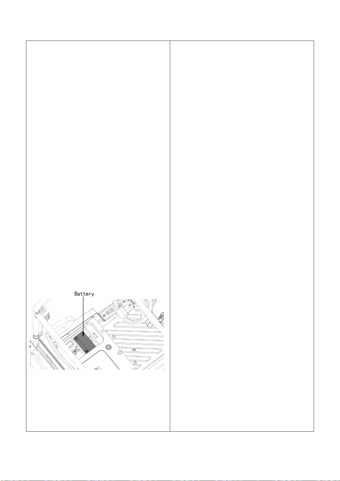
① Battery
2-4
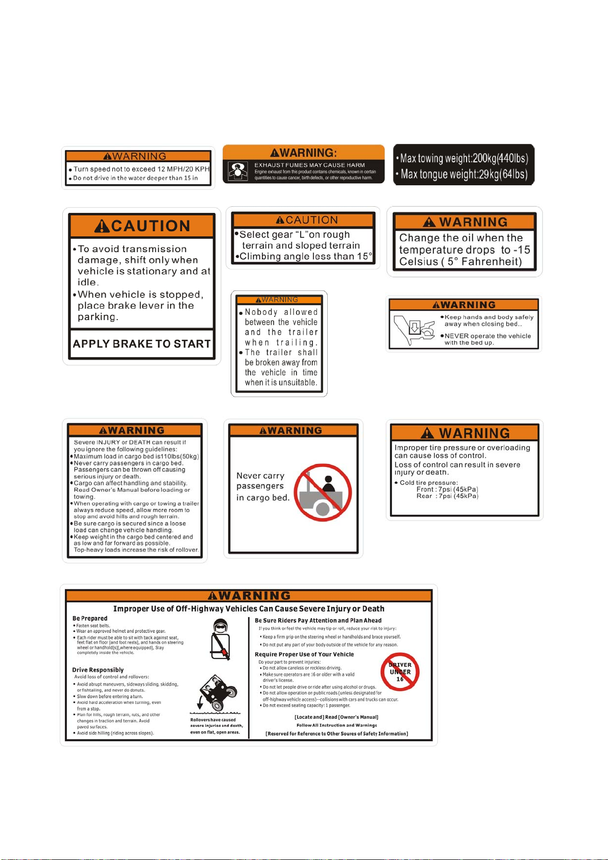
Warning Labels
Warning and caution labels
(1) (2) (3)
(4) (5) (6)
(7)
(9) (10) (11)
(8)
(12)
3-1
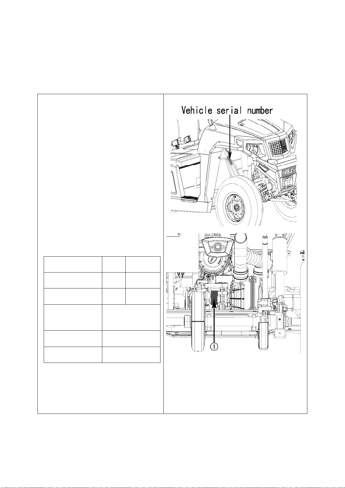
Vehicle Identification Number
SERVICING OF VEHICLE
Your dealer is interested in your new
vehicle and has the desire to help you get
the most value from it. After reading this
manual thoroughly, you will find you can do
some of the regular maintenance by
yourself.
However, when in need of parts or major
service, be sure to see your dealer.
For service, contact the dealership from
which you purchased your vehicle or your
local dealer.
When in need of parts, be prepared to give
your dealer both the vehicle and engine
serial numbers.
Locate the serial numbers now and record
them in the space provided.
Type Serial No.
Vehicle
Engine
Product Identification
Number
Date of Purchase
Name of Dealer
① Engine serial number
4-1

SPECIFICATION TABLE
Model Specification
Specifications
Make
Type
compression ratio 9.7±0.1:1
Bore × stroke mm
Displacement(s) cc
Engine
Rated net power kW (HP) 10.8(14.48)
Maximum power speed
rpm
Maximum torque (Nm) 17.5
Maximum torque speed (rpm) 5800
Low idle speed
(rpm) 1500±150
Spark plug
Fuel Capacity L
Transmission
Wheels
Differential lock
HS1P65MM
1 cylinder, 4-cycle, gasoline, SOHC, liquid
cooled
65.5×68.0
229cc
7000
DR8EA
13.5
CVT
4
Electric control: switch
Gear selection
Brakes
Steering
Suspension
Dimensions
Front/Rear
Parking brake
Front
Rear
Length mm(in.)
Width mm (in.)
Height mm (in.)
Wheelbase mm (in.)
Front tyre track mm(in.)
Rear tyre track mm (in.)
Forward overhang mm (in.)
Rear overhang mm (in.)
Hi-Lo range forward, Neutral, Reverse
Wet disk brake
Rear wheel, hand lever
Electronic power
Independent, Dual A-arm type
Independent, Dual A-arm type
2410 (94.9)
1235 (48.6)
1620 (63.8)
1706 (67.2)
985 (38.8)
970 (38.2)
344 (13.5)
360 (14.2)
5-1
Specifications
Model Specification
Ground Clearance mm (in.)
Turning diameter m (in.)
Max. rolling weight (Towing Capacity) kg (lbs.)
Payload capacity kg (lbs.)
Weight kg (lbs.)
Width mm (in.)
Length mm (in.)
Cargo bed
Depth mm (in.)
Cargo bed capacity kg (lbs.) 50 (110.2)
Front
Tire
Rear
Max speed (km/h) T3a:40 T3b:60
190 (7.5)
7 (275.6)
200 (440)
50 (110.2)
353 (778.2)
730 (28.7)
1020 (40.2)
250 (9.8)
180/85-10 or 175/85-10
255/60-10
NOTE:
The values in “Ground clearance” and “Weight” are those of the machine equipped with the tires
in the table above.
The company reserves the right to change the specifications without notice.
5-2

Specifications
VEHICLE LIMITATIONS
The Vehicle has been thoroughly tested for proper performance with implements sold or approved by
manufacturer. Use with implements which are not sold or approved and which exceed the maximum
specifications listed below, or which are otherwise unfit for use, vehicle may result in vehicle
malfunction or failures with a possibility of the vehicle damage, property damage and injury to the
operator or others. Any malfunctions or failures of the vehicle resulting from use with improper
implements are not covered by the warranty.
Max. Cargo loading weigh
Cargo Bed Capacity=50kg(110 lb)
Cargo Load Capacity=200kg(440 lb)
*(operator+one passenger+opt+acc )weight
1. Above mentioned specifications are based on level ground condition.
Max. rolling weight
200kg (440 lb.)
Max. tongue weight
29 kg (64 lb.)
5-3

Pre-Operation
DAILY CHECK
To better prevent troubles, it is important to
know condition of the vehicle well. Check it
before starting.
CAUTION:
To avoid personal injury:
Be sure to check and service the vehicle on
a level surface with the engine off, the
parking brake “ON” and implements
lowered to the ground if equipped.
Check items
- Visually inspect the exterior of the vehicle
-Check engine oil level
-Check transmission oil level
-Check brake fluid level
-Check coolant level
-Clean radiator screen
(When used in a dusty place)
The vehicle comes with the following key:
[1] Master key
-Check brake and pedal
-Check parking brake
-Check indicators, gauges and meters
-Check lights
-Check seat belts and roll-over protective
structures.
-Check front and rear joint boots.
-Check tire inflation pressure.
-Check backup beeper (if equipped).
-Refuel
(See "PRE-OPERATION CHECK" in
"PERIODIC SERVICE" section.)
-Check of danger, warning and caution labels
(See "DANGER, WARNING AND CAUTION
LABELS"in"SAFE OPERATION"section.)
6-1
Operating the Engine
CAUTION:
To avoid personal injury:
Read "SAFE OPERATION" in front of
this manual.
Read the danger, warning and caution
labels located on the vehicle.
To avoid the danger of exhaust fume
poisoning, do not operate the engine in
closed buildings without proper
ventilation.
Start engine only from operator’s seat.
Never start engine while standing on
ground.
Make it a rule to set gear shift lever to
“NEUTRAL” position before starting
the engine.
IMPORTANT:
Do not use starting fluid or ether.
To protect the battery and the starter,
make sure that the starter is not
STARTING THE ENGINE
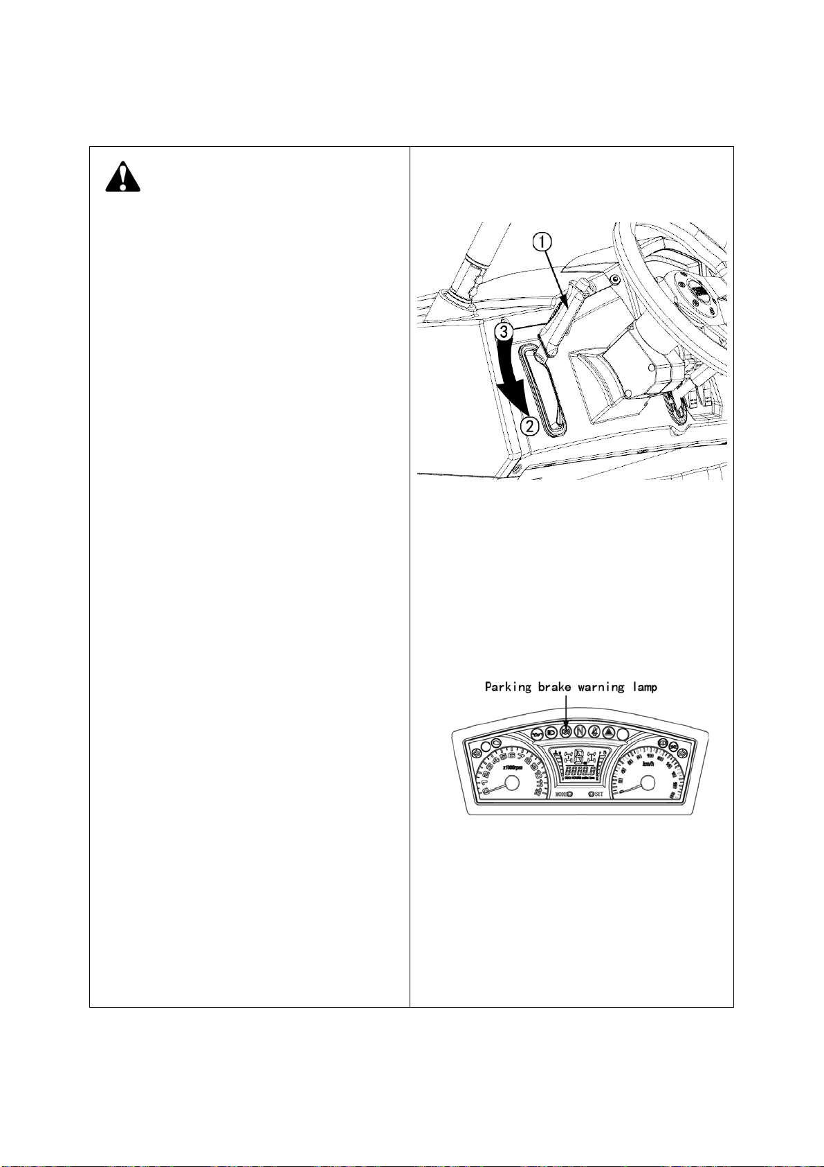
1. Make sure the parking brake is set.
① Parking brake lever ② Pull to “PARK”
③ Release
NOTE:
The parking brake warning lamp (P) comes on
while parking brake is applied and goes off
when it is released.
continuously turned for more than 5
seconds.
7-1
Operating the Engine
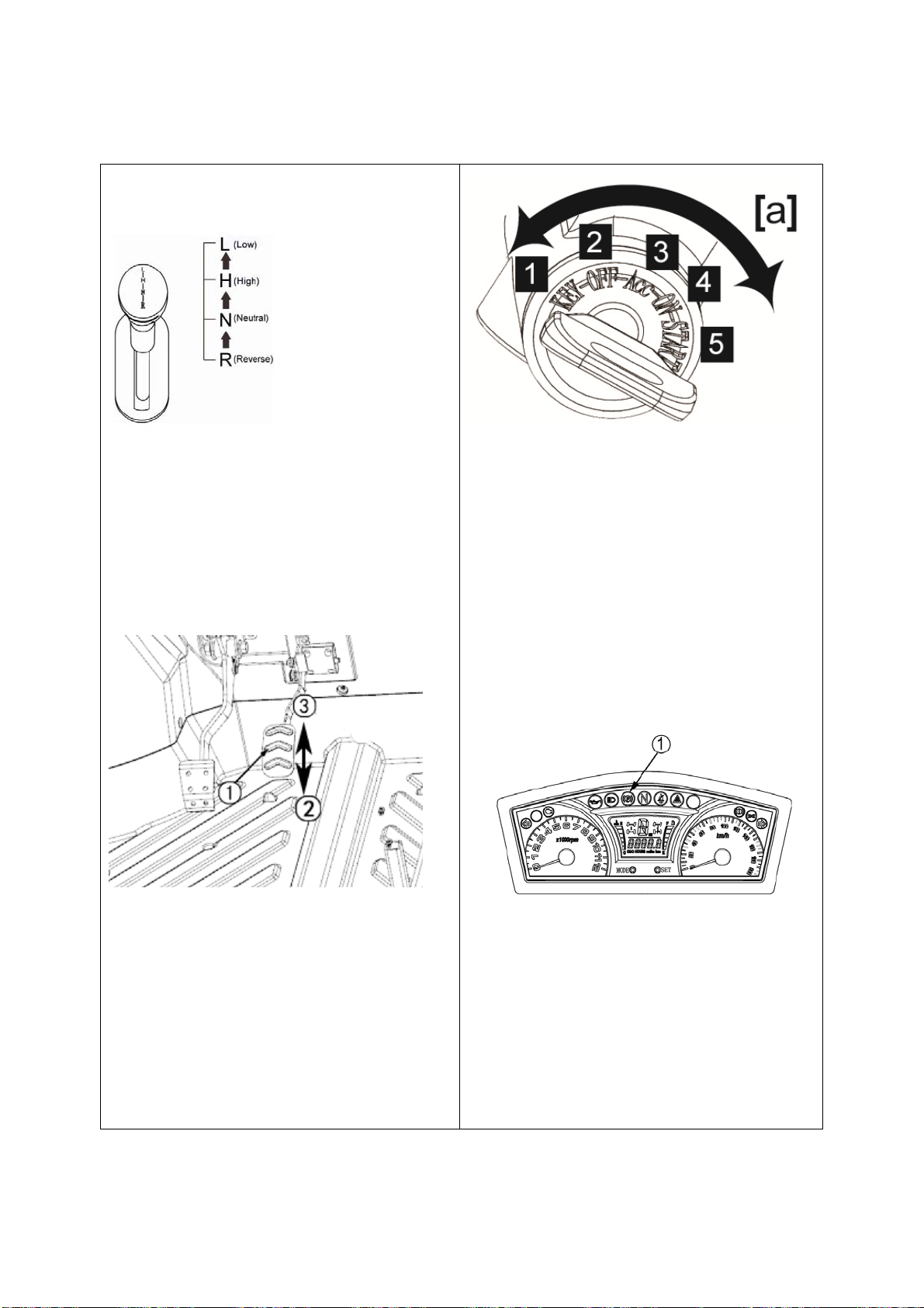
2.
Set gear shift lever to the “NEUTRAL”
position.
① Gear shift lever.
(L) Low Range
(H) High Range
(N) “Neutral” position
(R) “REVERSE”
3. Push the accelerator pedal down slowly.
4. Insert the key into the key switch and
turn it to:
OFF (Stop the Engine)
ON (Engine runs or headlights on)
START (Start the Engine)
◆ Engine and other Check Lamps:
The parking brake warning lamp (1 parking
① Speed control pedal
② INCREASE
③ “DECREASE
brake) comes on while parking brake is
applied and goes off when it is released.
IMPORTANT :
Relying on the engine warning lights is
never enough. Never fail to conduct daily
checks carefully by referring to Pre
Operation Check “ in “PERIODIC
SERVICE” section.
7-2

Operating the Engine
5. Turn the key to the “START” position
and release when the engine starts.
IMPORTANT:
Because of safety devices, the engine will
not start except when the gear shift lever
is placed in the “NEUTRAL” position and
the brake is depressed.
■ Cold Starting
When the ambient temperature is below 15℃( 5℉), the engine is very cold. If the
engine fails to start after 5 seconds, turn
off the key for 30 seconds and start again.
■ Cold Starting
When the ambient temperature is below -
For 5 minutes after engine start-up, allow the
engine to warm up without applying any load.
This is to allow oil to reach every engine part. If
load applied to the engine without warming-up,
troubles engine damage may occur.
■Warm-Up Transmission Oil in the Low
Temperature Range
IMPORTANT:
Do not operate the vehicle under full load
until it is sufficiently warmed up.
15℃( 5℉), the engine is very cold. If the
engine fails to start after 5 seconds, turn off
the key for 30 seconds and start again.
STOPPING THE ENGINE
1. After slowing the engine to idle, turn the
key to “OFF”.
2. Remove the key.
WARMING UP
CAUTION:
To avoid personal injury:
Be sure to set the parking brake during
warm-up.
Be sure to set the shift lever to the
“NEUTRAL” position during warm-up.
7-3

Operating the Vehicle
OPERATING NEW VEHICLE
How a new vehicle is handled and maintained
determines the life of vehicle.
A new vehicle just off the factory production
line has been, of course, tested, but the
various parts are not aligned to each other, so
the operator should pay more attention to
operating the vehicle for the first 50 hours at a
slower speed and avoid excessive work or
operation until the various parts become
“broken-in.” The manner to which you handle
the vehicle during “breaking-in” period greatly
affects the life of your vehicle. Therefore, to
obtain the maximum performance and the
longest life of the vehicle, it is very important to
properly break-in your vehicle. For better
handling of a new vehicle, the following
■ Changing Lubricating Oil for New
Vehicles
The lubricating oil is especially important for a
new vehicle. Various parts need time to wear
and polish themselves to the correct operating
clearances. Small pieces of metal grit may
develop during the operation of the vehicle;
and this may wear out or damage the parts.
Therefore, change the lubricating oil a little
earlier than would ordinarily be required. For
further details of change interval hours, see
“MAINTENANCE” section
STARTING
1. Fasten the seat belts during operation.
■ Seat Belt
precautions should be observed.
■ Do not operate the vehicle at full speed
for the first 50 hours.
Do not start quickly nor apply the brakes
suddenly.
In winter, operate the vehicle after fully
warming up the engine.
Do not run the engine at speeds faster
than prescribed.
On rough roads, slow down to suitable
speeds.
The above precautions are not limited to
new vehicles. However, they should be
especially observed for new vehicles.
WARNING
To avoid personal injury:
Seat belts reduce injury. Always wear
your seat belts. The lap-style seat belts
may not provide adequate protection
for small children. Pay special
attention when carrying a child
passenger.
CAUTION:
To avoid personal injury:
Always use the seat belts when
operating and riding the vehicle.
Adjust the seat belts for proper fit and connect
the buckle. This seat belt is an auto-locking
retractable type.
8-1

Operating the Vehicle
2. Selecting light switch position.
■ Head Light Switch
Turn on the key switch, head light on.
NOTE:
Turn on the key switch causes the following
lamps to light simultaneously.
1. Tail lights (lamps at the rear portions of the
vehicle)
2. Dashboard background Light
3. Front left and right position lights
④ Winch cable pulled up
⑤ Emergency light "ON"
⑥ Emergency light "OFF"
⑦ Left turning lights
⑧ Right turning lights
■ Emergency Light Switch
Press the top half of the emergency light
switch, the light flash along with the indicator
on the instrument panel. Press the bottom half
of the emergency light switch to turn off the
light.
Note:
The emergency light switch will operate
when the key switch is in the “ON” position
and "OFF" position. Keeping the switch
“ON” causes the battery to run out.
■ Turn Signal Light Switch
To indicate a right turn, push on the lower half
of the turn toggle switch.
To indicate a left turn, push on the upper half
① High beam lights "ON"
② Low beam lights "ON"
③ Winch cable release
of the turn toggle switch.
When the left or right signal is activated, the
indicated turning light will flash and the other
will stay on.
The indicator lamp at the instrument panel also
flashes indicating the direction of the turn.
NOTE:
The turn signal light switch is only
operative when the key switch is in the
ON” position.
If the emergency light switch is pressed to
the “ON” position while the turn signal is
8-2

Operating the Vehicle
activated, the indicated turning light will
flash and other will stay on.
Be sure to return switch to center position
after turning.
control or the shifting forward of heavy
loads.
When driving on icy, wet or loose
surface, make sure the vehicle is
correctly loaded to avoid skidding or
loss of steering control. Reduce the
speed.
The brake pedal is the left pedal on the foot
board. Depress the pedal to slow or stop the
vehicle.
① Head light
② Head turn signal lamp;
③ Tail turn signal lamp
3. Checking the brake pedal.
■ Brake Pedal
CAUTION:
To avoid personal injury:
If the operator suddenly brakes, an
accident may occur due to loss of
① Brake pedal
4. Selecting the correct gear.
■ Gear Shift Lever
CAUTION:
To avoid personal injury:
Avoid changing gears when ascending
or descending a slope.
Before ascending or descending a
slope, shift to the “L” range to control
the vehicle speed.
If you shift gears while ascending or
descending a slope, be prepared to use
the brake to maintain control.
Operate in reverse at slow speeds to
8-3

Operating the Vehicle
maintain control.
1. The gear shift lever can only be shifted
when the vehicle is completely stopped
and the brake pedal is pressed.
2. To avoid transmission and shift linkage
damage, completely stop the vehicle using
the brake pedal before shifting gears.
3. Select proper gear depending on the
types of job.
4. Before exiting vehicle, shift the gear shift
lever to the “NEUTRAL” position and set
parking brake.
the lever. Damage may occur with wrong
shifting operation.
AN accident could occur through improper
use of the gear shift lever
5. Release the parking brake and start
slowly.
To release the parking brake, depress the
brake pedal, push release button and push
release button and push down on the parking
brake lever. Make sure that the indicator in the
instrument panel goes off.
① Range gear shift lever
(L) LOW Range
(H) HIGH Range
(N) NEUTRAL” POSITION
(R) “REVEREE”
NOTE:
When gear shift lever is hard to engage,
do not force the lever. Set the parking
brake, slightly depress the accelerator
pedal and release it to neutral position,
then shift the lever.
When the lever is hard to disengage, do
not force the lever.
Depress the brake pedal fully, then shift
① Parking brake lever
② “RELEASE”
■ Accelerator Pedal
The Accelerator pedal is used to increase the
engine and vehicle speed. Push down on it for
higher speed.
8-4

Operating the Vehicle
① Accelerator pedal
STOPPING
■ STOPPING
1. Release the speed accelerator pedal
2. Step on the brake pedal.
■ Fuel Gauge
Park the vehicle on a flat place.
When the key switch to “ON”, the fuel gauge
will indicate the fuel level.
Be careful not to fully empty the fuel tank.
Otherwise air may enter the fuel system.
① Fuel gauge
■ Coolant Temperature Gauge
CHECK DURING DRIVING
■ Immediately Stop the Engine if:
The engine suddenly slows down or
accelerates.
Unusual noises are suddenly heard.
Exhaust fumes suddenly become very
white.
While driving, check the following items to see if
all parts are functioning normally.
CAUTION:
To avoid personal injury:
Do not remove radiator cap until coolant
temperature is well below its boiling
point. Then loosen cap slightly to relieve
pressure before removing cap
completely.
1. With the key switch “ON” the temperature
gauge indicates the temperature of the
coolant. White Zone for “cold” and Red zone
for “hot”.
2. If the indicator reaches the Red zone, the
engine coolant is overheated. Check the
vehicle by referring to
“TROUBLESHOOTING” section.
8-5

Operating the Vehicle
■ Speedometer
The hour meter indicates in five digits the
hours the vehicle has been used.
① Hour meter
The speedometer indicates the traveling
speed.
① Speedometer
8-6

Maintenance and Adjustment
WINCH MOUNT PLATE
Always read and follow the instructions in the winch owner’s manual before attempting to install or
use a winch.
■ Transporting Vehicle
Pay attention to the following points when transporting the vehicle.
1. Use a suitable truck or trailer.
2. Apply the parking brake and place chocks against the front and rear tires.
MAINTENANCE
CAUTION:
To avoid personal injury and vehicle damage:
Be sure you have sufficient knowledge, experience, the proper replacement parts and
tools before you attempt any vehicle maintenance task.
If you don’t have the knowledge and equipment which are necessary to perform the
maintenance task, consult your local dealer.
Have your local dealer perform inspection items which are marked *4 in the chart below.
SERVICE INTERVALS
IMPORTANT:
The jobs indicated by ◎ must be done after the first 50 hours of operation.
*1 Air cleaner should be cleaned more often in dusty conditions than in normal conditions.
*2 Every year or every 6 times of cleaning.
*3 Replace only if necessary.
*4 Consult your local dealer for this service.
9-1

Maintenance and Adjustment
*5 When the battery is used for less than 100 hours per year, check the battery condition by reading
the indicator annually.
The items listed below with a * mark are emission related critical parts by the U.S.EPA. As the
engine owner, you are responsible for the performance of the required maintenance on the
engine according to the below instruction. Please see Warranty Statement for more information.
○
Indication of
○
○
○
No. Items
1 Engine oil Change ◎ ○ ○ ○
2 Engine oil filter Replace ◎ ○ ○ ○
Transmission
3
fluid
Engine start
4
system
5 Greasing Apply ○ ○ ○ ○ ○ ○ ○ ○ ○ ○ ○ ○ ○ ○
6 *Muffler Clean ◎ ○ ○ ○ ○ ○ ○ ○
7 Spark arrester Clean ○ ○ ○ ○ ○ ○ ○
Wheel bolt
8
torque
9
Battery condition
10 Toe-in Adjust ○ ○ ○ ○ ○ ○ ○
Fuel filter
11
element
12 *Fuel line
*Air cleaner
13
element
14 Brake pedal Check ◎ ○ ○ ○
Parking brake
15
lever
Brake light
16
switch
Radiator hose
17
and clamp
18 *Intake air line
Change ○
Check ○ ○ ○ ○ ○ ○ ○ ○ ○ ○ ○ ○ ○ ○
Check ◎ ○ ○ ○ ○ ○ ○ ○
Check ○ ○ ○ ○ ○ ○ ○
Check ○ ○ ○ ○ ○ ○ ○
Replace ○
Check ○ ○ ○ ○ ○ ○ ○
Replace
Clean
Replace
Adjust ◎ ○ ○ ○
Check ◎ ○ ○ ○
Check ○ ○ ○
Replace
Check ○ ○ ○
Replace
50 100 150 200 250 300 350 400 450 500 550 600 650 700
○
○
9-2
After
700 hrs
Every
200 hrs
Every
200 hrs
Every
400 hrs
Every
50 hrs
Every
50 hrs
Every
100 hrs
Every
100 hrs
Every
100 hrs
Every
100 hrs
Every
100 hrs
Every
100 hrs
Every
100 hrs
Every
500 hrs
Every
100 hrs
○ Every 1
years
Every
100 hrs
Every 1
years
Every
200 hrs
Every
200 hrs
Every
200 hrs
Every 2
years
Every
200 hrs
Every 1
years

Maintenance and Adjustment
No. Items
Brake hose &
19
pipe
20 Tire wear Check
Front axle case
21
oil
22 Knuckle case oil Change ○
Engine valve
23
clearance
24 *Fuel injection Check
25 *Injection Check
26 Brake fluid Change
Remote
27
hydraulic hose
Rear brake
28
cylinder seal
29 Front brake seal Replace
30 Cooling system Flush
31 Coolant Change
32 Fuel system Bleed
33 Fuse Replace
34 Light bulb Replace
Check
Check Every 4years
Change ○
Adjust
Replace
Replace
50 100 150 200 250 300 350 400 450 500 550 600 650 700
◎
○ ○ ○
◎
○ ○
Indication of
After
700 hrs
Every
200 hrs
Every
300 hrs
Every
400 hrs
Every
400 hrs
Every
800 hrs
Every
1500 hrs
Every
3900 hrs
Every 2
years
Every 2
years
Every 2
years
Every 2
years
Every 2
years
Every 2
years
Service as
required
NOTE:
◆
Engine Oil:(10W/40SL)
Oil used in the engine should have an American Petroleum Institute (API) service classification and
Proper SAE Engine Oil according to the ambient temperatures as shown above.
◆
Brake fluid:
Always use DOT3 GENUINE BRAKE FLUID from a sealed container.
9-3

Periodic Service
CAUTION:
To avoid personal injury:
HOW TO OPEN THE HOOD AND
TILT THE SEAT
CAUTION
To avoid personal injury from contact with
moving parts:
Never open operator’s seat while the
engine is running.
Depress the hood with your other hand
while unlocking
■ Hood
To open the hood, turn the switch to release
the latch and lift the hood off.
the hood.
① Operator’s seat
WARNING
POTENTIAL HAZARD
Aloose seat.
WHAT CAN HAPPEN
The operator could lose control or the
operator or passenger could fall if the seat
is loose during operation.
HOW TO AVOID THE HAZARD
Make sure the seat is mounted firmly.
■ Moving the Seat Forward and
Backward.
Pull handle 1 driver's seat can move forward
and backward, the seat is adjusted to adapt to
the height of different drivers.
■ Operator’s Seat
To open the seat, raise the seat to the forward
position.
10-1

Periodic Service
HOW TO RAISE THE CARGO BED
CAUTION
To avoid personal injury:
● When servicing under raised bed, make
sure safety support is properly
mounted.
● Do not touch muffler or exhaust pipes
while they are hot; Otherwise, severe
burns could result.
■ Raising and Lowering the Cargo Bed
◆ To raise the cargo bed
1. Apply the parking brake with the engine
off.
2. Pull up the cargo bed handle.
NOTE:
Pull up the cargo bed handle to raise the cargo
bed with the gas spring elasticity.
gas spring contractive till it is locked.
① Gas spring
Front and Rear Shock Adjustment
The spring preload can be adjusted to suit
rider’s weight and any passenger weight.
NOTE:
Never turn an adjusting mechanism beyond
the minimum and maximum settings.
Adjust the spring proud as follows.
To increase the spring preload, turn the
adjusting ring in direction (a).
To decrease the spring preload, turn the
adjusting ring in direction (b).
① Cargo bed handle
② UP
③ DOWN
◆ To lower the cargo bed
Press down the cargo bed hard to make the
1. Spring preload adjusting ring
2. Position indicator
10-2

Periodic Service
NOTE:
A special wrench can be obtained at a dealer
to make this adjustment.
Standard position: B
A- Minimum (soft)
E- Maximum (hard)
1. Special wrench
WARNING
blocking.
■ Front End
Jack stand at the front bumper only.
① Jack ② Front bumper
■ Rear End
POTENTIAL HAZARD
Improper shock absorber adjustment.
WHAT CAN HAPPEN
Uneven adjustment can cause poor handling
and loss of stability, which could lead to an
accident.
HOW TO AVOID THE HAZARD
Always adjust the shock absorbers on the left
and right side to the same setting.
JACK-UP POINT
WARNING
To avoid personal injury, death or vehicle
damage:
Do not work under the vehicle unless it is
secured by safe stands or suitable
Jack the rear only after placing a wooden block
under the right and left frame tubes for
securing the engine and then supporting it.
Do not apply jack pressure on the steel plate
directly under the engine.
① Jack
10-3

Periodic Service
DAILY CHECK
For your own safety and maximum service life
of the vehicle, make a thorough daily
inspection before starting the engine or
operating the vehicle.
CAUTION
To avoid personal injury:
Be sure to check and service the
vehicle on a flat surface with the engine
off and the parking brake “ON”.
■ Walk Around Inspection
Look around and under the vehicle for such
items as loose bolts, trash build-up, oil or
coolant leaks, broken or worn parts
■ Checking and Refueling
CAUTION
To avoid personal injury:
the seat, open the adjust hatch cover.
2. To check the oil level, draw out the
dipstick, wipe it clean, replace it, and draw
it out again, check to see if the level is too
low, add new oil to the prescribed level on
the dipstick.
~①② Oil level is acceptable within this range
① Oil Level
② Oil dipstick
④ Oil cap
■ Checking Coolant Level
Do not smoke while refueling.
Be sure to stop the engine before
refueling.
1. Turn the key switch to “ON”, check the
amount of fuel by the fuel gauge.
2. Fill fuel tank when fuel gauge shows1/4 or
less fuel in the tank.
Fuel tank capacity
IMPORTANT
If oil level is low, do not run the engine.
Checking engine oil level
1. Park the vehicle on a flat surface, remove
13.5 (3.6±0.1U.S.GALS)
10-4
CAUTION
TO avoid personal injury
Do not remove radiator cap while
coolant is hot .when cool .slowly rotate
to the first stop and allow sufficient
time for excess pressure to escape
removing the cap completely.
1. Park the vehicle on a flat surface, access
the panel under the hood, set the parking
brake, and shut off the engine.
2. Check to see that the coolant level is
between the “FULL” and” LOW” marks of
recovery tank.
3. When the coolant level drops due to

Periodic Service
evaporation, add water only up to the full level.
In case of leakage add anti-freeze and water in
the specified mixing ratio up to the full
level.(see flush cooling system and changing
coolant in EVERY 2 YEARS in PERIODIC
SERVICE section)
① Recovery tank
② FULL
③ LOW
IMPORTANT
If the radiator cap has to be removed,
follow the cautions above and securely
retighten the cap.
Use clean fresh water and anti-freeze to fill
the recovery tank.
If water should leak, consult your local
HSUN Dealer.
■ Cleaning radiator screen
3. Detach the screen and remove all foreign
materials.
① Radiator screen
IMPORTANT
Radiator screen must be cleaned from debris
to prevent engine from overheating
■ Checking brake fluid level
CAUTION
TO avoid personal injury:
Never operate the vehicle if the brake
fluid is below the m i nimum mark.
Use only DOT3 from a sealed
container. Other types of brake fluid
may ruin synthetic resin or rubber
installed in brake system components
CAUTION
TO avoid personal injury:
Be sure to stop the engine before
removing the screen
1. Park the vehicle on a flat surface,
2. Remove the radiator cover,
10-5
and may cause brake failure.
Avoid clean contamination of the brake
fluid thoroughly before removing the
filler cap. Do not open the brake fluid
reservoir cap unless absolutely
necessary.

Periodic Service
Use extreme care when filling the reservoir.
If brake fluid spills on the power steering
hose, wash it off with water immediately, as
brake fluid quickly ruins synthetic resin or
rubber hoses.
1. Park the vehicle on a level ground and
open the hood.
2. Check to see that the brake fluid level is
up to the MIN mark.
3. If it is below the “MIN” mark add brake
fluid .
① MAX ② MIN
■ Checking brake pedal
① Brake pedal ② FREE TRAVEL
③ PEDAL STROKE
■ Checking parking br ak e
Pull the parking brake lever to apply the
brakes with the key switch in the "ON" position
and the parking brake indicator should come on.
To release the brake, push in the button on the
tip of the parking brake lever and tilt the lever
down.
CAUTION
TO avoid personal injury:
Stop the engine and chock the wheels
before checking brake pedal.
1.Inspect the brake pedals for free play and
smooth operation.
Adjust if incorrect free play is found. (see
checking brake pedal in” EVERY 200 HOURS
in PERIODIC SERVICE section)
10-6
NOTE
Make sure the parking brake warning lamp on
the display goes off when parking brake lever
and tilt the lever down.
NOTE
Make sure the parking brake warning lamp on
the display goes off when parking brake lever
is down.

Periodic Service
① Parking brake lever ② Release button
RELEASE③ ④ PULL
■ Checking gauges meter and warning
lamps
tire sizes inflation pressure
Front :
180/85-10 or
175/85-10
Rear :
255/60-10
45kPa (0.46kgf/cm
45kPa (0.46kgf/cm2, 7psi)
2
, 7psi)
EVERY 50 HOURS
■ Greasing
Apply a small amount of multi-purpose grease
to the following points every 50 hours. If you
operated the vehicle in extremely wet and
muddy conditions lubricate grease fittings
more often.
1. Inspect the instrument panel for broken
gauges meter and warning lamps.
2. Replace if broken.
■ Checking head light turn signal light etc
1. Inspect lights for broken bulbs and lenses
2. Replace if broken
■ Checking seat belt and ROPS
1. Always check condition of seat belt and
ROPS attaching hardware before
operating vehicle.
2. Replace if damaged.
■ Checking tire inflation pressure
Though the tire pressure is factory-set to the
prescribed level, it naturally drops slowly in the
course of time, thus check it every day and
inflate as necessary.
① Parking brake pivot (spray type grease )
10-7

Periodic Service
① Cargo brace rod turning point(spray type grease )
② Cargo bed rotating axle (spray type grease)
■ Checking engine start system
CAUTION
TO avoid personal injury
Do not allow anyone near the vehicle
while testing.
If the vehicle does not pass the test, do
not operate the vehicle.
◆ Preparation before testing
1. Place all control levers in the “NEUTRAL”
position.
2. Set the parking brake and stop the
engine.
◆ T est gear shift range lever safety switch
1. Sit on the operator's seat.
2. Shift the gear shift range lever to: “L”, “H”,
“N” or REVERSE position.
3. Turn the key to “START” position.
4. The engine must not crank.
5. If it cranks consult your local dealer for
this service.
① Gear shift lever pivot (spray type grease )
① Gear shift lever
10-8

Periodic Service
① Accelerator pedal
■ Checking wheel bolt torque
CAUTION
To avoid personal injury
Never operate vehicle with a loose
wheel bolts.
Any tine these bolts are loosened they
■ Cleaning air cleaner primary element
1. Remove the air cleaner cover and primary
element.
2. Clean the primary elements.
1) When dry dust adheres to the element
blow compressed air from the inside
turning the element. Pressure of
compressed air must be under 205kpa.
2) When carbon or oil adheres to the
element soak the element in detergent for
15 minutes then wash it several times in
water rinse with clean water and dry it
naturally after element is fully dried
inspect inside of the element with a light
and check if it is damaged or not.
3) Replace the primary element
Once yearly or after every sixth cleaning,
whichever comes first.
should be retightened to the specified
torque.
Check all bolts frequently and keep
them tight.
Check wheel bolts regularly especially when
new if they are loose tighten them as follows:
① Torque wheel bolts to 75 to 90 N.m
① First air cleaner ② Air cleaner case
③ Air cleaner element ④ Cover
IMPORTANT
The air cleaner uses a dry element never
apply oil.
10-9

Periodic Service
Do not run the engine with filter element
contaminated with water replace it.
removed.
Be sure to refit the cower with the arrow
(on the rear of cower ) upright. if the cover
is improperly fitted the evacuator valve will
not function and dust will adhere to the
element.
◆ Evacuator Valve
Open the air cleaner cover once a week under
ordinary conditions –or daily when used in a
dusty place-to get rid of large particles of dust
and dirt.
Check fuel line and fuel filter.
CAUTION
To avoid personal injury:
Be sure to stop the engine and remove
the key when attempting to make the
following checks and changes.
Never fail to check the fuel lines
periodically the fuel lines are subject to
wear and aging fuel may leak out onto
IMPORTANT
When the fuel line is disconnected for
maintenance or repair, close both ends of the
fuel line with a piece of clean cloth or paper to
prevent dust and dirt from entering. Particular,
care must be taken not to admit dust and dirt
into the fuel pump entrance. Even a small
amount of dust or dirt will cause premature
wear and malfunction of the fuel pump and
injector components.
① Pipe clamp ② fuel line
③ fuel pump
■ Checking battery condition
the running engine causing a fire.
The fuel line connections should be
checked annually or every 100 service
hours whichever comes first.
1. Park the vehicle on a flat surface and tilt
the cargo bed.
2. The fuel line is made of rubble and ages
regardless of service period.
3. If the fuel line and clamps are found to be
damaged or deteriorated replace them.
4. Check fuel filter if it is clogged by debris or
10-10
DANGER
If you store a battery in a diminished state
of charge you will probably have to replace
the battery.
CAUTION
To avoid personal injury
Never remove the battery while the
engine is running.

Periodic Service
Keep electrolyte away from eyes, hands
and clothes. If you are spattered with it,
wash it away completely with water
immediately and get medical attention.
Wear eye protection and rubber gloves
when working around the battery.
The factory –installed battery is non-refillable
type if the battery is weak, charge the battery
or replace it with new one
◆ Battery charging
CAUTION
To avoid personal injury
When the battery is being activated,
hydrogen and oxygen gases in the
battery are extremely explosive. keep
open sparks and flames away from the
battery at all times, especially when
charging the battery.
When disconnecting the cable from the
battery start with the negative terminal
first; when connection the cable to the
battery start with the positive terminal
first.
① Battery
1. To slow charge the battery connect the
battery positive terminal to the charger
positive terminal and the negative to the
negative, then recharge in the standard
fashion.
2. A boost charge is only for emergencies it
will partially charge the battery as early as
possible.
3. When exchanging an old battery for a new
one use battery of equal specification
shown in table 1.
Battery type Volts
Always check battery charge by using a
voltmeter.
10-11
12V8Ah 12
◆ Direction for storage
1. When storing the vehicle for a long period,
remove the battery from the vehicle, store
in a dry place out of direct sunlight.
2. The battery will self-discharge while it is
shored; recharge it once every three
months in hot seasons and once every six

months in cold seasons.
■ Adjusting toe-in
Periodic Service
■ Cleaning Muffler
CAUTION
To avoid personal injury:
Proper toe-in 0 to12 mm (0 to 0.47 in)
1. Park vehicle on flat place.
2. Turn steering wheel so front wheels are in
the straight ahead position.
3. Lock the park brake and stop the engine.
4. Measure distance between front tire beads
at rear of tire at hub height.
5. Front distance should be shorter than rear
distance if not adjust tie rod length.
① Wheel-to-wheel distance at front
② Wheel-to-wheel distance at rear
③ FRONT
◆ Adjusting procedures
1. Loosen the lock nut and turn the tie rod to
2. Retighten the lock nut.
IMPORTANT
Keep the equal length of the left and right
adjust the rod length until the proper toe-in
measurement is obtained.
tie-rod.
Before touching any part of an exhaust
system, be absolutely sure that it has
sufficient time to cool!
Always wear safety goggles and face
mask.
The particulate matter contained in the
muffler contains chemicals that are
harmful to people, animals and marine
life.
If you are unable to do this work, have
it done by your dealer.
Cleaning spark arrester of muffler.
Maintenance & cleanout procedure:
The screen type spark arrester should be
removed, cleaned, and inspected after
every 100 hours of use.
1. The spark arrester is located inside of the
muffler body, and fastened with bolts.
2. Loosen the bolts and remove the spark
arrester.
3. Shake loosened particles out of the
screen assembly and lightly clean the
screen with wire brush. Soak in solvent
and again clean with wire brush if
necessary.
4. If any breaks in the screen or welds are
discovered, the assembly must be
replaced.
5. Return the spark arrester to the muffler
body and refasten the bolts.
10-12

IMPORTANT:
Periodic Service
2. To drain the used oil, remove the drain
Visually check the muffler for cracks or
holes in the body, welds or pipes at regular
intervals.
USDA approval requires clearance
between spark arrester sleeve and muffler
body to be no larger than 0.023”(0.584
mm).
Replace the entire muffler if it is damaged.
Do not operate the vehicle with a
damaged muffler.
① Muffler ② Gasket
③ Spark arrester ④ Bolt
EVERY 200 HOURS
■ Changing Engine Oil
plug at the bottom of the engine and
completely drain the oil into an oil pan.
3. After draining, reinstall the drain plug.
4. Fill with the new oil up to the upper notch
on the dipstick.
(See “LUBRICANTS, FUEL AND
COOLANT” in “MAINTENANCE” section.)
[Filter exchanged] 0.8L (1.89U.S. qts.)
Oil capacity
[Filter non-exchanged] 1.0L (1.68U.S. qts.)
~①② Oil level is acceptable within this range
③ Dipstick ④ Oil inlet
CAUTION
To avoid personal injury:
Be sure to stop the engine before
replacing oil.
Allow engine to cool down sufficiently,
oil can be hot and can burn. oil can be
hot and can burn.
1. Park the vehicle on flat surface and
remove the seat, open the adjust hatch
cover.
10-13
① Drain plug

■ Replacing Engine Oil Filter
Periodic Service
■ Checking Brake Pedal
CAUTION
To avoid personal injury:
Be sure to stop the engine before
changing the oil filter cartridge.
Allow engine to cool down sufficiently,
oil can be hot and can burn.
1. Park the vehicle on a flat surface and raise
the cargo bed.
2. Remove the oil filter.
3. Put a film of clean engine oil on the rubber
seal of the new filter.
4. After the new filter has been replaced, the
engine oil normally decreases a little.
Make sure that the engine oil does not
leak through the seal and check the oil
level on the dipstick. Then replenish the
engine oil up to the prescribed level.
CAUTION
Stop the engine and chock the wheels
before checking brake pedal.
If movement is outside of the
specifications contact your local dealer for
adjusting the brake.
◆ Checking the brake pedal free travel
Proper brake pedal
free travel
1. Release the parking brake.
2. Slightly depress the brake pedal and
measure free travel at the top of the pedal
stroke.
3. If brake pedal free travel is outside of the
specifications, contact your local dealer
7 to 14mm(0.3 to in.)
On the pedal
[1] Engine oil filter
[2] Bolt
IMPORANT:
To prevent serious damage to the engine, use
only a genuine filter.
for adjusting the brake.
◆ Checking the brake pedal stroke
Less than 120mm (4.7in.)
Pedal stroke
On the pedal
1. Release the parking brake.
2. Step on the pedal and measure the pedal
stroke.
3. If brake pedal stroke is outside of the
specifications, contact your local dealer
for adjusting the brake.
10-14

Periodic Service
① Brake pedal
② “FREE TRAVEL” ③ “PEDAL STROKE”
■ Checking Brake Hose and Pipe
1. Check to see that brake hose and lines
1. If hose clamps are loose or water leaks,
tighten bands securely.
2. Replace hoses and tighten hose clamps
securely, if radiator hoses are swollen,
hardened or cracked. Replace hoses and
hose clamps every 2 years or earlier, if
checked and found that hoses are
swollen, hardened or cracked.
are not swollen, hardened or cracked.
2. Check the brake hose and pipe joints for
oil leaks.
3. If there is any abnormality, consult your
local dealer for this service.
■ Checking Brake Light Switch
1. Park the vehicle on a flat surface and raise
the cargo bed.
2. Turn the key switch to the “ON” position.
3. Step on the brake pedal to check if the
brake light comes on.
4. If it does not, check the bulb or brake light
switch.
■ Checking Radiator Hose and Clamp
Park the vehicle on a flat surface and raise the
cargo bed. Check to see if radiator hoses are
properly fixed every 200 hours of operation or
six months, whichever comes first.
① Radiator hose ② Clamp bands
◆ Precaution at Overheating
Take the following actions in the event the
coolant temperature is close to or more than
the boiling point, which is called “Overheating”.
1. Stop the vehicle operation in a safe place
and keep the engine unloaded idling.
2. Don’t stop the engine suddenly, but stop it
after about 5 minutes of unloaded idling.
3. Keep yourself well away from the vehicle
for at least 10 minutes or while the steam
is blowing out.
4. Check to see if there is no danger such as
burning, get rid of the causes of
overheating according to the
“TROUBLESHOOTING” section of the
10-15

Periodic Service
manual, and then start the engine again.
■ Checking Intake Air Line
1. Check to see if the hoses and hose
clamps are tight and not damaged.
2. If hoses and clamps are found to be worn
or damaged, replace or repair them at
once.
① 3mm(0.12in)
EVERY 500 HOURS
■ Replacing Fuel Filter
① Hose ② Hose clamp
EVERY 300 HOURS
■ Checking Tire
1. Check to see if tires are not damaged.
2. If the tires are cracked, bulged, or cut, or
they are worn out, replace or repair them
at once.
◆ Tire Tread Depth
Always replace the tires when the tread depth
is worn to minimum allowable.
Consult your local dealer for this service.
EVERY 600 HOURS
■ Adjusting Engine Valve Clearance
Consult your local dealer for this service.
EVERY 1500 HOURS
■ Checking I njection and Fuel Pump
Consult your local dealer for this service.
EVERY 1 YEAR
■ Replacing Air Cleaner Primary Element
and Secondary Element
(See “Cleaning Air Cleaner Primary
Element” in “every 100 HOURS” in
“PERIODIC SERVICE” section.)
EVERY 2 YEARS
■ Changing Brake Fluid
Consult your local Dealer for this service.
10-16

Periodic Service
(See “Checking Brake Fluid Level” in “DAILY
CHECK” in “PERIODIC SERVICE” section.
■ Flushing Cooling System and Changing
Coolant
CAUTION
To avoid personal injury:
Do not remove the radiator cap while
coolant is hot. When cool, slowly rotate
cap to the first stop and allow sufficient
time for excess pressure to escape
before removing the cap completely.
Coolant capacity 2.2(2.3U.S.qts)
1. Stop the engine and let it cool down.
2. To drain the coolant, open the radiator
drain plug and remove radiator cap. The
radiator cap must be removed to
completely drain the coolant.
3. After all coolant is drained, close the drain
plug.
4. Fill with clean water and cooling system
cleaner.
5. Follow directions of the cleaner container.
6. After flushing, fill with clean water and
anti-freeze until the coolant level is just
below the radiator cap. Install the radiator
cap securely.
7. Fill with fresh water up to the “FULL” mark
on the recovery tank.
8. Start and operate the engine for few
minutes.
9. Stop the engine and let it cool.
10. Check coolant level of recovery tank and
coolant if necessary.
① Recovery tank “ FULL”②
③ “ LOW” Radiator cap④
IMPORTANT:
Do not start engine without coolant.
Use clean, fresh water and anti-freeze to
fill the radiator and recovery tank.
When the anti-freeze is mixed with water,
the antifreeze mixing ratio must be less
than 50%.
Securely tighten radiator cap. If the cap is
loose or improperly fitted, water may leak
out and the engine could overheat.
■ Anti-Freeze
CAUTION
To avoid personal injury:
When using antifreeze, put on some
protection such as rubber
gloves.(Antifreeze contains poison.)
10-17

Periodic Service
If you should drink antifreeze, throw up at
the antifreeze and the ambient
once and take medical attention.
When antifreeze comes in contact with the
skin or clothing, wash it off immediately.。
Do not mix different types of Antifreeze.
The mixture can produce chemical reaction
causing harmful substances.
Antifreeze is extremely flammable and
explosive under certain conditions. Keep
fire and children away from antifreeze.
When draining fluids from the engine,
place some container underneath the
engine body.
Do not pour waste onto the grounds, down
a drain, or into any water source.
Also, observe the relevant environmental
protection regulations when disposing of
antifreeze.
If it freezes, coolant can damage the cylinders
and radiator. If the ambient temperature falls
°
below 0 (32℃
F) or before a long-term storage,
let out cooling water completely, or mix fresh
water with long-life coolant and fill the radiator
and recovery tank with the mixture.
1. Long-life coolant (hereafter LLC) comes in
several types. Use ethylene glycol(EG)
type for this engine.
2. Before employing LLC-mixed cooling
water, fill the radiator with fresh water and
empty it again.
Repeat this procedure 2 or 3 times to
clean up the inside.
3. Mixing the LLC
4. The procedure for the mixing of water and
antifreeze differs according to the make of
temperature. Refer to SEA J1034
standard, more specifically also to SAE
J814c.
IMPORTANT:
When the antifreeze is mixed with water,
the antifreeze mixing ratio must be less
than 50%.
VOL%
Anti-freeze
40 -24 -12 106 222
50 -37 -34 108 226
Freezing point Boiling point
℃
°
F ℃
°
F
*At 1.013×10⁵Pa (760mmHg) pressure
(atmospheric).
A higher boiling point is obtained by using a
radiator pressure cap which permits the
development of pressure within the cooling
system.
5. Adding the LLC
1) Add only water if the mixture reduces in
amount by evaporation.
2) If there is a mixture leak, add the LLC of
the same manufacturer and type in the
same mixture percentage.
* Never add any long-life coolant of
different manufacturer.(Different brands
may have different additive components,
and the engine may fail to perform as
specified.)
6. When the LLC is mixed, do not employ
any radiator cleaning agent. The LLC
10-18

Periodic Service
contains anticorrosive agent. If mixed with
■ Replacing Rear Brake Cylinder Seal
the cleaning agent, sludge may build up,
adversely affecting the engine parts.
7. The vehicle’s genuine long-life coolant has
a service life of 2 years. Be sure to change
the coolant every 2 years.
NOTE:
The above data represent industry
standards that necessitate a minimum
glycol content in the concentrated
antifreeze.
When the coolant level drops due to
evaporation, add water only to keep the
antifreeze mixing ratio less than 50%. In
case of leakage, add antifreeze and water
in the specified mixing ratio before filling
into the radiator.
Consult your local dealer for this service.
■ Replacing Intake Air Line
Consult your local dealer for this service.
EVERY 4 YEARS
■ Replacing Brake Hose
Consult your local Dealer for this service.
■ Replacing Mini Fuses
The Mini fuses are intended to protect the
electrical cabling. If any of them have blown
out, be sure to pinpoint the cause.
◆ Replacing procedure
1) Disconnect the negative cable of the
battery.
■ Replacing Radiator Hose (Water pipes)
Replace the hoses and clamps.
(See “Checking Radiator Hose and Clamp” in
“EVERY 200 HOURS” in “PERIODIC
SERVICE” section.)
■ Replacing Fuel Hose
Consult your local Hisun Dealer for this
service.
■ Replacing Brake Master Cylinder (Inner
parts)
Consult your local dealer for this service.
■ Replacing Front Brake Seal
Consult your local dealer for this service.
2) Open the Mini fuse box cover.
3) Pull out the Mini fuse.
4) Insert a new Mini fuse into the box.
5) Close the Mini fuse box cover.
6) Connect the negative battery cable.
① Mini fuse box cover
10-19

■ Replacing Light Bulb
Periodic Service
and tighten if necessary.
Head lights
Take the bulb out of the light body and
replace it with a new one.
Other lights
Detach the lens and replace the bulb
Light Capacity
Head lights 2x35W/2×55W
Tail light 2 x0.6W/2 x0.6W
Brake light 2x1W/2 x1W
Instrument panel light 0.02W
STORAGE
CAUTION
To avoid personal injury:
Do not clean the vehicle when the
engine is running.
2. Apply grease to vehicle areas where bare
metal will rust also to pivot areas.
3. Unload from cargo bed.
4. Inflate the tire to a pressure a little higher
than usual.
5. Charge the engine oil and run the engine
to circulate oil throughout the engine block
and internal moving parts for about 5
minutes.
6. With all implements lowered to the
ground, coat any exposed rods with
grease (if equipped).
7. Remove the battery from the vehicle.
Store the battery following the battery
storage procedures.
8. Keep the vehicle in a dry place where the
vehicle is sheltered from the elements.
To avoid the danger of exhaust fume
poisoning, do not operate the engine in
a closed building without proper
ventilation.
When storing, remove the key from the
key switch to avoid unauthorized
persons from operating the vehicle and
getting injured.
VEHICLE STORAGE
If you intend to store your vehicle for an
extended period of time, follow the procedures
outlined below.
These procedures will insure that the vehicle is
ready to operate with minimum preparation
when it is removed from storage.
1. Check the bolts and nuts for looseness.
Cover the vehicle.
9. Keep the vehicle indoors in a dry area that
is protected from sunlight and excessive
heat. If the vehicle must be stored
outdoors. Cover it with a waterproof
tarpaulin.
Put boards under the tires to keep
dampness away from tire.
Keep the tries out of direct sunlight and
extreme heat.
IMPORTANT:
When washing the vehicle, be sure to
stop the engine.
Allow sufficient time for the engine to cool
before washing.
Do not wash with a high-pressure car-
10-20

Periodic Service
washing machine.
Cover the vehicle after the muffler and the
engine have cooled down.
REMOVING THE VEHICLE FROM
STORAGE
1. Check the tire air pressure and inflate the
tires if they are low.
2. Install battery before installing the battery,
Be sure it is fully charged.
3. Check to see if the fan works.
4. Check all fluid levels (engine oil,
transmission oil, engine coolant,
transmission coolant and any attached
implements).
5. Start the engine. Observe all gauges. If all
gauges are functioning properly and
reading normal, move the vehicle outside.
Once outside, park the vehicle and let the
engine idle for at least five minutes. Shut
the engine off and work around vehicle
and make a visual inspection looking for
evidence of oil or water leaks.
6. With the engine fully warm up. Release the
parking brake and test the brakes for
proper adjustment as you move forward.
Adjust the brake as necessary.
10-21

Hitch coupling device
Basicinformation
Hitch coupling device is the device linking
tractor and trailer.
Coupling ball are parts that are subject to type
approval and that connect vehicles, and are
therefore subject to the highest safety
requirements.
They may only be operated with the compliant
Coupling head that have been approved.
Coupling ball are produced in accordance
with the Regulation (EU)2015/208.
Adapt your driving to the road conditions
when towing a trailer. Towing a trailer affects
the handling of a vehicle. Always follow the
vehicle manufacturer’s operating instructions.
Specifications of the vehicle manufacturer
regarding trailer and torque load set the
standards for vehicle operation.
Values specified for the tow bar must not be
exceeded.
T : Total weight of the vehicle in t
R : Total weight of the trailer in t
2
g : acceleration due to gravity, 9.81 m/s
Always observe the standard fixing points
specified by the vehicle manufacturer.
Always observe national guidelines
concerning official approval of extensions.
These installation and operating instructions
have to be kept with the vehicle documents.
Installation instructions
The Coupling ball is a safety component and
should only be installed by qualified
personnel.
The Coupling ball can be easily installed and
removed with the normal force of your hands.
Any alteration and/or conversion of the
device will be locked automatically.
Coupling ball is prohibited and will result in
the cancellation of the type approval.
①Hitch Ball ②Hitch Joint Q
The steps to link hitch rod and
vehiclebody:
Fasten the connecting hitch rods and the
hitch ball to ensure that when the tow truck is
connected to the trailer, the hitch ball is
ensured to be safety connected.
Attension:
1. Hitch weight≤200kg,
Vertical weight≤29kg.
2. Hitch heavy weight, drive the vehicle
cautiously and slowly.
3.When using the trailer, people should stay
away from the hitch coupling device.
4.When not using trailer, must sperete the
trailer and car.
5.Hitch coupling device only applies to the
tow bar trailer.
NOTE
When you no longer use a trailer, you must
remove the trailer from the tractor and lay it
flat.
When the trailer is connected to the tow truck,
it’s prohibited to stay between the trailer and
the tow truck.
11-1

Troubleshooting
ENGINE TROUBLESHOOTING
If something is wrong with the engine, refer to the table below for the cause and its corrective
countermeasure.
Trouble Cause Countermeasure
Check the fuel tank and fuel
filter。
Check the electric fuel pump.
Check the injector.
Check the ECU with Motor Scan
KF90121.
Replace filter electric fuel pump
injector and ECU If necessary.
Check to see if the fuel tank cover
is tight.
,
Use oils of different viscosities,
depending on ambient temperatures.
Clean battery cables and terminals.
Charge the battery.
In cold weather (-15 ),℃ always
remove the battery from the vehicle,
charge and store it indoors. install
it on the vehicle only when the
vehicle is going to be used。
Check the fuel system.
Clean or replace the injector.
Replace crankshaft position sensor.
Clean or replace the air cleaner.
Clean or replace the spark plug.
Replace the ignition coil.
Fill cooling system to the correct
level;
Check radiator and hoses for
loose connections or leaks.
Check to see if the fuse is not blown.
Check the electric system.
Remove all trash.
Engine is difficult to start or
cannot start.
Engine power is
insufficient
Engine stops suddenly
Engine overheats
No fuel flow
·Water is in the fuel system
In winter, oil viscosity increases
and Engine revolution is slow.
Battery becomes weak and
the engine does not turn over
quick enough.
Insufficient fuel.
The injector is clogged.
Crankshaft position sensor is
Bad.
The air cleaner is clogged.
Spark plug is dirty or fouled.
Ignition coil is bad.
Check with the diagnostic
instrument (Motor Scan
KF90121 ).
Engine overloaded Shift to lower gear or reduce load.
Low coolant level.
The motor driven fan does
not turn.
Dirty radiator core or grille
screens.
Coolant flow route corroded. Flush cooling system.
If you have any questions, consult your local dealer.
12-1

Troubleshooting
Diagnostic Trouble Code Table
Mt05 ECU Malf Code
Table:23
Malf code in MT05 Description
P0107 MAP Circuit Low Voltage or Open
P0108 MAP Circuit High Voltage
P0112 IAT Circuit Low Voltage
P0113 IAT Circuit High Voltage or Open
P0117 Coolant/Oil Temperature Sensor Circuit Low Voltage
P0118 Coolant/Oil Temperature Sensor Circuit High Voltage or Open
P0122 TPS Circuit Low Voltage or Open
P0123 TPS Circuit High Voltage
P0131 O2A Circuit Low Voltage
P0132 O2A Circuit High Voltage
P0031 O2A Heater Circuit High Voltage
P0032 O2A Heater Circuit Low Voltage
P0201 Injector 1 Circuit Malfunction
P0202 Injector 2 Circuit Malfunction
P0230 FPR Coil Circuit Low Voltage or Open
P0232 FPR Coil Circuit High Voltage
P0336 CKP Sensor Noisy Signal
P0337 CKP Sensor No Signal
P0351 Cylinder 1 Ignition Coil Malfunction
P0352 Cylinder 2 Ignition Coil Malfunction
P0505 Idle Speed Control Error
P0562 System Voltage Low
P0563 System Voltage High
P0650 MIL Circuit Malfunction
P1693 Tachometer Circuit Low Voltage
P1694 Tachometer Circuit High Voltage
P0137 O2S 2 Circuit Low Voltage
P0138 O2S 2 Circuit High Voltage
P0038 O2S Heater 2 Circuit High Voltage
P0037 O2S Heater 2 Circuit Low Voltage
12-2

Troubleshooting
MT05 ECU Malf Code
Table:23
Malf code in MT05 Description
P0500 VSS No Signal
P0850 Park Neutral Switch Error
P0445 CCP short to high
P0444 CCP short to low/open
P0171 BLM Max Adapt(Kohler Special)
P0172 BLM Min Adapt(Kohler Special)
P0174 PE System Lean(Kohler Special)
If you have any questions, consult your local dealer.
12-3

Troubleshooting
BATTERY TROUBLESHOOTING
Trouble Cause Countermeasure Preventive measure
Battery overused
Starter does not function
From beginning starter
does not function, and
lights soon become dim
When viewed from the
top of plates, look
whitish.
* Refillable type battery
only
until lights are dim.
Battery has not
been recharged.
Poor terminal
connection
Battery life expired
Insufficient
charging
Battery was used
with an insufficient
amount of
electrolyte.
Battery was used
with too much
without recharging.
Charge the battery
sufficiently.
Clean the terminal
and tighten
securely.
Replace new
battery
Charge battery
Insufficiently
Add distilled water
and charge the
battery.
Charge battery
Insufficiently
Charge the battery
properly.
Keep the terminal
clean and tight.
Apply grease and
treat with anti-corrosive.
Battery must be
serviced properly
before initial use
Regularly check the
electrolyte level.
Charge battery
properly
Recharging is impossible
Terminals are severely
corroded and heat up.
Battery electrolyte level
drops rapidly.
* Refillable type battery
only
If you have any questions, consult your local dealer.
The factory installed battery is non-refillable type.
. Battery life expired. Replace battery.
Poor terminal
connection
There is a crack or
pin holes in the
electrolytic cells.
Charging system
trouble.
Clean the terminal
Replace battery.
Consult your local
12-4
and tighten
securely.
dealer.
Keep the terminal
clean and tight.
Apply grease and
treat with anti-
corrosives.

Troubleshooting
MACHINE TROUBLESHOOTING
Trouble Cause Countermeasure
High idling speed of engine
High rotary speed for clutch
connection.
Non agility for Gearshift
Non good adjust for gearshift
stay wire.
Gear abrasion Replace the gears
Big matching clearance for the
inner and outside gears of
transmission shaft
Transmission noise
Less vehicle power
No good brake or noise
Big clearance of transmission
gears.
Non good connection of gear
end face
Parking brake Loosen the lay-up rod
Non full Uncoupling for disc
brake
CVT transmission sliding
Less brake oil Check the braking oil level
Air inside the braking system. Contact the distributor.
Brake discs abrasion Contact the distributor.
Assembling bolt of disc plate
loose
Assembling bolt for disc brake
clippers loose
Replace throttle cable;
Replace throttle petal
Replace the throttle
Replace he junior clutch spring;
Replace the primary clutch.
Put the gearshift rod into the
position of “N”.
Put the gearshift arm of engine
into ”N”.
Adjust the stay wire and the bolt.
Lock tightly.
Replace the gears
Replace the gears
Replace the gears
Contact the distributor.
Removing the grease for the
clutch.
Replace CVT transmission belt
Replace the clutch.
Lock tightly
Lock tightly
If you have any questions, consult your local dealer.
12-5

OPTIONS
Consult your local dealer for further details.
1. Roof;
2. Windscreen;
3. Windlass
4. Motor Scan KF90121;
13-1

Declaration of Driver’s exposure to noise level
The undersigned: Mr. Li Guanxiang, Director
Company name and address of the manufacturer:
Chongqing Huansong Science And Technology Industrial Co.,Ltd
Yanjia Industrial Park, Changshou District, Chongqing,China
Hereby declares that:
For the following vehicle:
1.1. Make (trade name of the manufacturer): HSUN
1.2. Type:HS164-4
1.2.1. Variant(s): HS164-4
1.2.2. Version(s): A
1.2.3. Commercial name(s) (if available): N.A
1.2.4. Type-approval number(s) of the previous stage(s): N.A
1.3. Category, subcategory and speed index of the vehicle: T3a
The Driver’s exposure to noise level result is 88.8 dB(A)(Limit: 86 dB(A)) according to
test method 1 of Annex XIII to EU 1322/2014.
Place: Chongqing, China Date: July 2018
Signature: Name and position in the company: Mr. Li Guanxiang, Director

Declaration of Driver’s exposure to noise level
The undersigned: Mr. Li Guanxiang, Director
Company name and address of the manufacturer:
Chongqing Huansong Science And Technology Industrial Co.,Ltd
Yanjia Industrial Park, Changshou District, Chongqing,China
Hereby declares that:
For the following vehicle:
1.1. Make (trade name of the manufacturer): HSUN
1.2. Type:HS164-4
1.2.1. Variant(s): HS164-4
1.2.2. Version(s): B
1.2.3. Commercial name(s) (if available): N.A
1.2.4. Type-approval number(s) of the previous stage(s): N.A
1.3. Category, subcategory and speed index of the vehicle: T3b
The Driver’s exposure to noise level result is 89.9 dB(A)(Limit: 86 dB(A)) according to
test method 1 of Annex XIII to EU 1322/2014.
Place: Chongqing, China Date: July 2018
Signature: Name and position in the company: Mr. Li Guanxiang, Director

Declaration of Vibration declaration
The undersigned: Mr. Li Guanxiang, Director
Company name and address of the manufacturer:
Chongqing Huansong Science And Technology Industrial Co.,Ltd
Yanjia Industrial Park, Changshou District, Chongqing,China
Hereby declares that:
For the following vehicle:
1.1. Make (trade name of the manufacturer): HSUN
1.2. Type: HS164-4
1.2.1. Variant(s): HS164-4
1.2.2. Version(s): A
1.2.3. Commercial name(s) (if available): N.A
1.2.4. Type-approval number(s) of the previous stage(s): N.A
1.3. Category, subcategory and speed index of the vehicle: T3a
The value of the vibration level measured according to Annex XIV to EU 1322/2014 is
59± 1kg
98± 5kg
Driver mass a
Test run 1 1.22
Test run 2 1.24
Arithmetic mean 1.23
Test run 1 1.21
Test run 2 1.22
Arithmetic mean 1.22
m/s2 Requirement
wS
Deviation<10% between test
run 1/2 and Arithmetic mean,
a
<1.25 m/s2
wS
Deviation<10% between test
run 1/2 and Arithmetic mean,
a
<1.25 m/s2
wS
awS:rms value of the weighted seat vibration acceleration measured during a standard
roadway test
Place: Chongqing, China Date: July 2018
Signature: Name and position in the company: Mr. Li Guanxiang, Director

The undersigned: Mr. Li Guanxiang, Director
Company name and address of the manufacturer:
Chongqing Huansong Science And Technology Industrial Co.,Ltd
Yanjia Industrial Park, Changshou District, Chongqing,China
Hereby declares that:
For the following vehicle:
1.1. Make (trade name of the manufacturer): HSUN
1.2. Type: HS164-4
1.2.1. Variant(s): HS164-4
1.2.2. Version(s): B
1.2.3. Commercial name(s) (if available): N.A
1.2.4. Type-approval number(s) of the previous stage(s): N.A
1.3. Category, subcategory and speed index of the vehicle: T3b
The value of the vibration level measured according to Annex XIV to EU 1322/2014 is
59± 1kg
98± 5kg
Driver mass a
Test run 1 1.22
Test run 2 1.24
Arithmetic mean 1.23
Test run 1 1.21
Test run 2 1.22
Arithmetic mean 1.22
m/s2 Requirement
wS
Deviation<10% between test
run 1/2 and Arithmetic mean,
a
<1.25 m/s2
wS
Deviation<10% between test
run 1/2 and Arithmetic mean,
a
<1.25 m/s2
wS
awS:rms value of the weighted seat vibration acceleration measured during a standard
roadway test
Place: Chongqing, China Date: July 2018
Signature: Name and position in the company: Mr. Li Guanxiang, Director
 Loading...