

Page 1
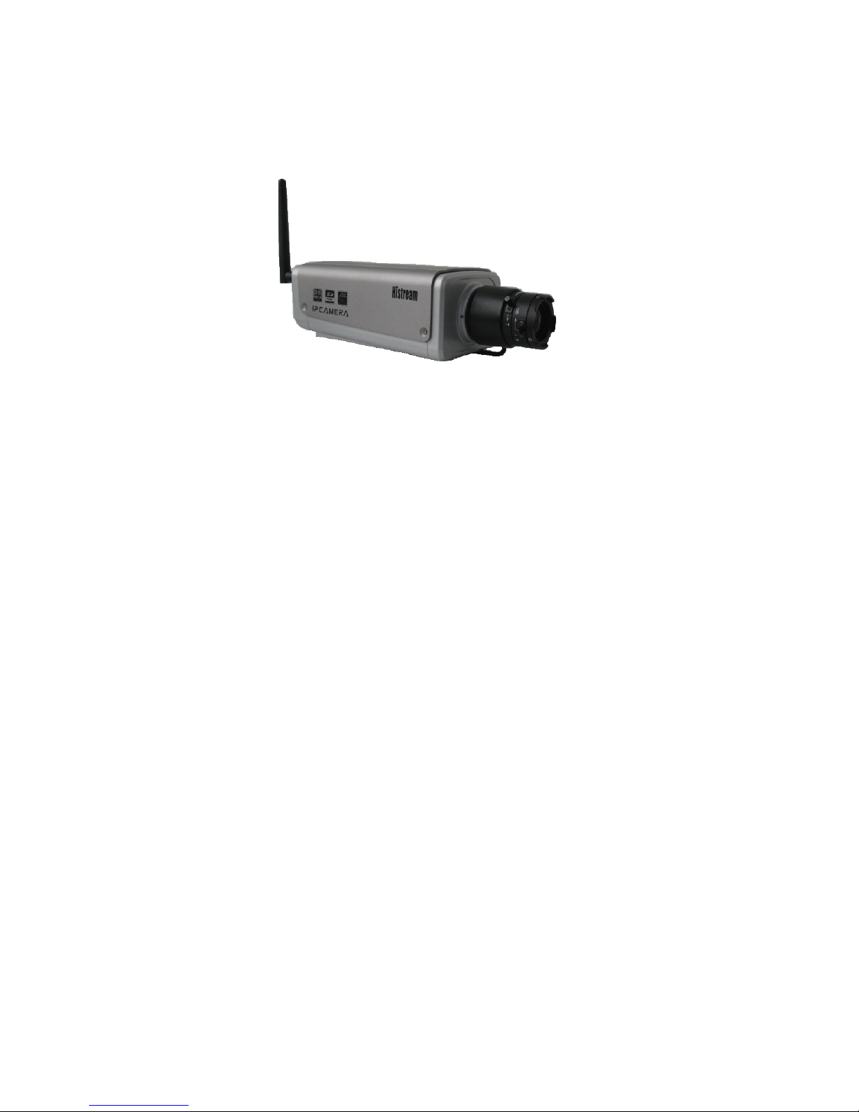
Mega
Mega
Mega
Mega Pixel
Pixel
Pixel
Pixel IP
IP
IP
IP Camera
Camera
Camera
Camera
----User
----User
----User
----User Manual
Manual
Manual
Manual
Packing List:
1. Mega Pixel IP Camera 1 pc
2. DC12V Power Adapter 1 pc
3. User Manual 1pc
4. CD 1pc
5. Warranty Card 1pc
Our corporation reserves the right to make any update to this manual without
notice.
Page 2

Mega
Mega
Mega
Mega Pixel
Pixel
Pixel
Pixel IP
IP
IP
IP Camera
Camera
Camera
Camera User
User
User
User Manual
Manual
Manual
Manual
1 / 35
Contents
Contents
Contents
Contents
1 Product Overview
. . . . . . . . . . . . . . . . . . . . . . . . . . . . . . . . . . . . . . . . . . . . . . . . . . . . . . . . . . . . . . . . . . . . . . . . . . . . . . . . . . . . . . . . . . . . . . . . . . . . . . . . . . . . . . . . . . . . . . . . . . . . . . .
2
1.1 Main Features
. . . . . . . . . . . . . . . . . . . . . . . . . . . . . . . . . . . . . . . . . . . . . . . . . . . . . . . . . . . . . . . . . . . . . . . . . . . . . . . . . . . . . . . . . . . . . . . . . . . . . . . . . . . . . . . . . . . . . . . . . . . .
2
1.2 Basic Specification
. . . . . . . . . . . . . . . . . . . . . . . . . . . . . . . . . . . . . . . . . . . . . . . . . . . . . . . . . . . . . . . . . . . . . . . . . . . . . . . . . . . . . . . . . . . . . . . . . . . . . . . . . . . . . . . . .
3
1.3 Hardware requirement
. . . . . . . . . . . . . . . . . . . . . . . . . . . . . . . . . . . . . . . . . . . . . . . . . . . . . . . . . . . . . . . . . . . . . . . . . . . . . . . . . . . . . . . . . . . . . . . . . . . . . . . . . . . .
4
2 Appearance and Installation
. . . . . . . . . . . . . . . . . . . . . . . . . . . . . . . . . . . . . . . . . . . . . . . . . . . . . . . . . . . . . . . . . . . . . . . . . . . . . . . . . . . . . . . . . . . . . . . . . . . . . . . . . . . . .
5
2.1 Backside connection of mega pixel IP Camera
. . . . . . . . . . . . . . . . . . . . . . . . . . . . . . . . . . . . . . . . . . . . . . . . . . . . . . . . . . . . . . . . . . . . . .
5
2.2 Hardware installation
. . . . . . . . . . . . . . . . . . . . . . . . . . . . . . . . . . . . . . . . . . . . . . . . . . . . . . . . . . . . . . . . . . . . . . . . . . . . . . . . . . . . . . . . . . . . . . . . . . . . . . . . . . . . . . . . .
5
3 Searching device and installing ActiveX
. . . . . . . . . . . . . . . . . . . . . . . . . . . . . . . . . . . . . . . . . . . . . . . . . . . . . . . . . . . . . . . . . . . . . . . . . . . . . . . . . . . . . . . .
6
3.1 Searching device and modify network parameters
. . . . . . . . . . . . . . . . . . . . . . . . . . . . . . . . . . . . . . . . . . . . . . . . . . . . . . . . . . . . . . . . . . .
6
3.2 Checking connection
. . . . . . . . . . . . . . . . . . . . . . . . . . . . . . . . . . . . . . . . . . . . . . . . . . . . . . . . . . . . . . . . . . . . . . . . . . . . . . . . . . . . . . . . . . . . . . . . . . . . . . . . . . . . . . . . .
8
3.3 Installing ActiveX and login device
. . . . . . . . . . . . . . . . . . . . . . . . . . . . . . . . . . . . . . . . . . . . . . . . . . . . . . . . . . . . . . . . . . . . . . . . . . . . . . . . . . . . . . . . . .
8
4. Software configuration for mega pixel IP Camera
. . . . . . . . . . . . . . . . . . . . . . . . . . . . . . . . . . . . . . . . . . . . . . . . . . . . . . . . . . . . . . . . . . . .
10
4.1 Liveview
. . . . . . . . . . . . . . . . . . . . . . . . . . . . . . . . . . . . . . . . . . . . . . . . . . . . . . . . . . . . . . . . . . . . . . . . . . . . . . . . . . . . . . . . . . . . . . . . . . . . . . . . . . . . . . . . . . . . . . . . . . . . . . . . . .
10
4.2 Playback
. . . . . . . . . . . . . . . . . . . . . . . . . . . . . . . . . . . . . . . . . . . . . . . . . . . . . . . . . . . . . . . . . . . . . . . . . . . . . . . . . . . . . . . . . . . . . . . . . . . . . . . . . . . . . . . . . . . . . . . . . . . . . . . . . . .
12
4.3 System
. . . . . . . . . . . . . . . . . . . . . . . . . . . . . . . . . . . . . . . . . . . . . . . . . . . . . . . . . . . . . . . . . . . . . . . . . . . . . . . . . . . . . . . . . . . . . . . . . . . . . . . . . . . . . . . . . . . . . . . . . . . . . . . . . . . . . .
14
4.4 Video
. . . . . . . . . . . . . . . . . . . . . . . . . . . . . . . . . . . . . . . . . . . . . . . . . . . . . . . . . . . . . . . . . . . . . . . . . . . . . . . . . . . . . . . . . . . . . . . . . . . . . . . . . . . . . . . . . . . . . . . . . . . . . . . . . . . . . . . .
15
4.5 Motion alarm
. . . . . . . . . . . . . . . . . . . . . . . . . . . . . . . . . . . . . . . . . . . . . . . . . . . . . . . . . . . . . . . . . . . . . . . . . . . . . . . . . . . . . . . . . . . . . . . . . . . . . . . . . . . . . . . . . . . . . . . . . . . .
17
4.6 Sensor alarm
. . . . . . . . . . . . . . . . . . . . . . . . . . . . . . . . . . . . . . . . . . . . . . . . . . . . . . . . . . . . . . . . . . . . . . . . . . . . . . . . . . . . . . . . . . . . . . . . . . . . . . . . . . . . . . . . . . . . . . . . . . . .
18
4.7 Network fault alarm
. . . . . . . . . . . . . . . . . . . . . . . . . . . . . . . . . . . . . . . . . . . . . . . . . . . . . . . . . . . . . . . . . . . . . . . . . . . . . . . . . . . . . . . . . . . . . . . . . . . . . . . . . . . . . . . . .
18
4.8 Network
. . . . . . . . . . . . . . . . . . . . . . . . . . . . . . . . . . . . . . . . . . . . . . . . . . . . . . . . . . . . . . . . . . . . . . . . . . . . . . . . . . . . . . . . . . . . . . . . . . . . . . . . . . . . . . . . . . . . . . . . . . . . . . . . . . .
19
4.9 Advanced
. . . . . . . . . . . . . . . . . . . . . . . . . . . . . . . . . . . . . . . . . . . . . . . . . . . . . . . . . . . . . . . . . . . . . . . . . . . . . . . . . . . . . . . . . . . . . . . . . . . . . . . . . . . . . . . . . . . . . . . . . . . . . . . . .
20
4.10 User management
. . . . . . . . . . . . . . . . . . . . . . . . . . . . . . . . . . . . . . . . . . . . . . . . . . . . . . . . . . . . . . . . . . . . . . . . . . . . . . . . . . . . . . . . . . . . . . . . . . . . . . . . . . . . . . . . . .
22
4.11 Terminal
. . . . . . . . . . . . . . . . . . . . . . . . . . . . . . . . . . . . . . . . . . . . . . . . . . . . . . . . . . . . . . . . . . . . . . . . . . . . . . . . . . . . . . . . . . . . . . . . . . . . . . . . . . . . . . . . . . . . . . . . . . . . . . . . .
22
4.12 Storage set
. . . . . . . . . . . . . . . . . . . . . . . . . . . . . . . . . . . . . . . . . . . . . . . . . . . . . . . . . . . . . . . . . . . . . . . . . . . . . . . . . . . . . . . . . . . . . . . . . . . . . . . . . . . . . . . . . . . . . . . . . . . . . .
23
4.13 Local set
. . . . . . . . . . . . . . . . . . . . . . . . . . . . . . . . . . . . . . . . . . . . . . . . . . . . . . . . . . . . . . . . . . . . . . . . . . . . . . . . . . . . . . . . . . . . . . . . . . . . . . . . . . . . . . . . . . . . . . . . . . . . . . . . .
24
Appendix 1 Network Interface for IP Camera
. . . . . . . . . . . . . . . . . . . . . . . . . . . . . . . . . . . . . . . . . . . . . . . . . . . . . . . . . . . . . . . . . . . . . . . . . . . . . . . . .
25
Appendix 2 Network Parameters Default
. . . . . . . . . . . . . . . . . . . . . . . . . . . . . . . . . . . . . . . . . . . . . . . . . . . . . . . . . . . . . . . . . . . . . . . . . . . . . . . . . . . . . . . .
25
Appendix 3 Visits IP Camera under different network environment
. . . . . . . . . . . . . . . . . . . . . . . . . . . . . . . . . . . . . . . . . . .
26
Page 3

2 / 36
1
1
1
1 Product
Product
Product
Product Overview
Overview
Overview
Overview
1.1 Main Features
User can visit the mega pixel ip camera live image and playback in IE .
It support s max 10 users visit it at the same time.
Local PC storage or network storage permitted, it is built-in SD slot and supports
several n etwork storage protocols .
Max resolution 1600x1200.
Support CDMA1X and GRPS Mobile network.
Support local or remote arming or disarming.
Support warning detecting and gang video recording scheme. Sending the snapped picture or
alarm message by email or FTP server.
Support video masking, can be set 4 video mask areas.
Set motion detection to alarm for recording, it supports 4 detecting areas.
Sending alarm message and snapshot to user by email or FTP upload.
Support many network protocols, for example, HTTP , TCP/IP ,
UDP,
SMTP , DDNS, DNS,
SNTP ,BOOTP, DHCP,
FTP,
RTSP,
SNMP , and so on.
Network self-adapting to match the network bandwidth for the bit rate and frame rate.
Support DDNS, LAN and Internet (ADSL 、 Cable Modem).
Provide alarm message for Video Lost, Motion Detection (sensitivity and area can be set) and
Sensors.
Support remote configuration, remote upgrade, and remote error testing and automatic
recovery.
1.2
1.2
1.2
1.2 Basic
Basic
Basic
Basic Specification
Specification
Specification
Specification
Page 4

3 / 36
1.3
1.3
1.3
1.3 Hardware
Hardware
Hardware
Hardware requirement
requirement
requirement
requirement
The lowest configuration for hardware
Image Sensor
CMOS : 1/3 inch d einterlace CMOS sensor. Min 1 .5Lux
Video Compression
H.264 Main Profile
Two Streaming
Primary and Secondary streaming H.264 & MJPEG
Video Resolution
CMOS: 1600*1200, 1280*960, 1280*720 .
Video Parameters
CMOS: Brightness, Chroma, Saturation, gamma, Contrast, Acutance, Red,
Blue and Image quality.
Streaming Type
Pure Video Streaming or Audio and Video streaming.
Video Frame rate
CMOS: 1-30 fps , can be set under different resolution.
Video Compression
bit rate
30Kbit/S ~ 8MKbit/S
Audio Input
1 channel linear input, input impedance 1 K Ohms
Audio Compression
G.726, G.711, ADPCM
Audio Output
1 channel Linear output
Two-way talk input
Support Audio two-way talk
Local Recording
Support SD card to record the image and snapshot. SD2.0 standard.
Support IP-San storage.
System Interface
10Base-T/100Base-TX Ethernet Port
WiFi ( 802.11b/g )
1 RS485
USB port
SD Slot
Alarm Input
1 channel on/off input, Support NO(open),or NC(closed)
Alarm Output
1 channel on/off output, 120VAC 1A/24VDC 1A
PoE
POE standard 802.3AF-class 0
Power Supply
DC 12V 1A
Power Consumption
Less than 6W
Work T emperature
-10 ℃ ~ 55 ℃
Work Humidity
10% ~ 85%
Storage
Temperature
-20 ℃ ~ 70 ℃
Page 5

4 / 36
◆ CPU: Pentium 2.8 GHz
◆ Memory: 512 MB
◆ Graphic Card: TNT2
◆ Sound Card: Speaker, Two-way talk
◆ Hard Disk: Bigger than 40G
Recommended configuration for hardware
◆ CPU: Dual-core 2.6GMhz
◆ Memory: 1G B
◆ Graphic Card: Nvidia Geforce FX5200 or
ATI
RADEON 7000(9000) series 256 M B video
memory
Operation System
◆ 32 bit Windows2000, Windows
XP,
Windows2003, Windows Vista and
64 bit Windows2003 、 Windows
XP.
Software
◆ IE 6.0 or Better
◆ DirectX8.0 or Better
◆ TCP / IP protocol
PC system other requirement
The PC graphics card is required to support conversion and zoom in & out of image color. The
tested VGA are as follows: Nvidia Tnt/Tnt2, Geforce Mx200/400/420/440, Fx5200/5600 and its
series;
ATIR
adeon7000/7200/7500/8500/9000/9200/9500/9600and its series , MatroxG450/550;
INTEL845G/865G and its series. Please attend that the driving of graphics card must support
hardware zoom in & out function.
Page 6
5 / 36
2
2
2
2 Appearance
Appearance
Appearance
Appearance and
and
and
and Installation
Installation
Installation
Installation
2.1
2.1
2.1
2.1 Backside
Backside
Backside
Backside connection
connection
connection
connection of
of
of
of mega
mega
mega
mega pixel
pixel
pixel
pixel IP
IP
IP
IP Camera
Camera
Camera
Camera
�
Note :
The power input DC12V 50Hz 1A.Don ’ t use other power supply to damage the mega
pixel ip camera.
Explanations:
Explanations:
Explanations:
Explanations:
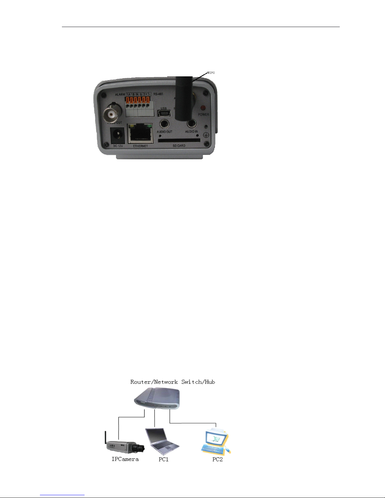
LAN: Ethernet Port
RST:
Reset Button (default set)
DC12V: Power Supply, DC 12V/1A
A
out: Audio Output
A
in: Audio Input
SD Card: SD Card slot
AUTO IRIS: Auto Iris port, support DC Lens
ANT:
WiFi interface
ALM out: 1 Alarm output
ALM in: 1 Alarm Input
GND: Signal ground, alarm ground, RS485 ground
RS485: RS485 Control interface, connect
to
Pan/Tilt or encoder , support many protocols
SD Card
:
SD slot
2.2
2.2
2.2
2.2 Hardware
Hardware
Hardware
Hardware installation
installation
installation
installation
2.2.1Connecting
2.2.1Connecting
2.2.1Connecting
2.2.1Connecting mega
mega
mega
mega pixel
pixel
pixel
pixel IP
IP
IP
IP camera
camera
camera
camera through
through
through
through
Router
Router
Router
Router /Network
/Network
/Network
/Network Switch/Hub
Switch/Hub
Switch/Hub
Switch/Hub
Page 7
6 / 36
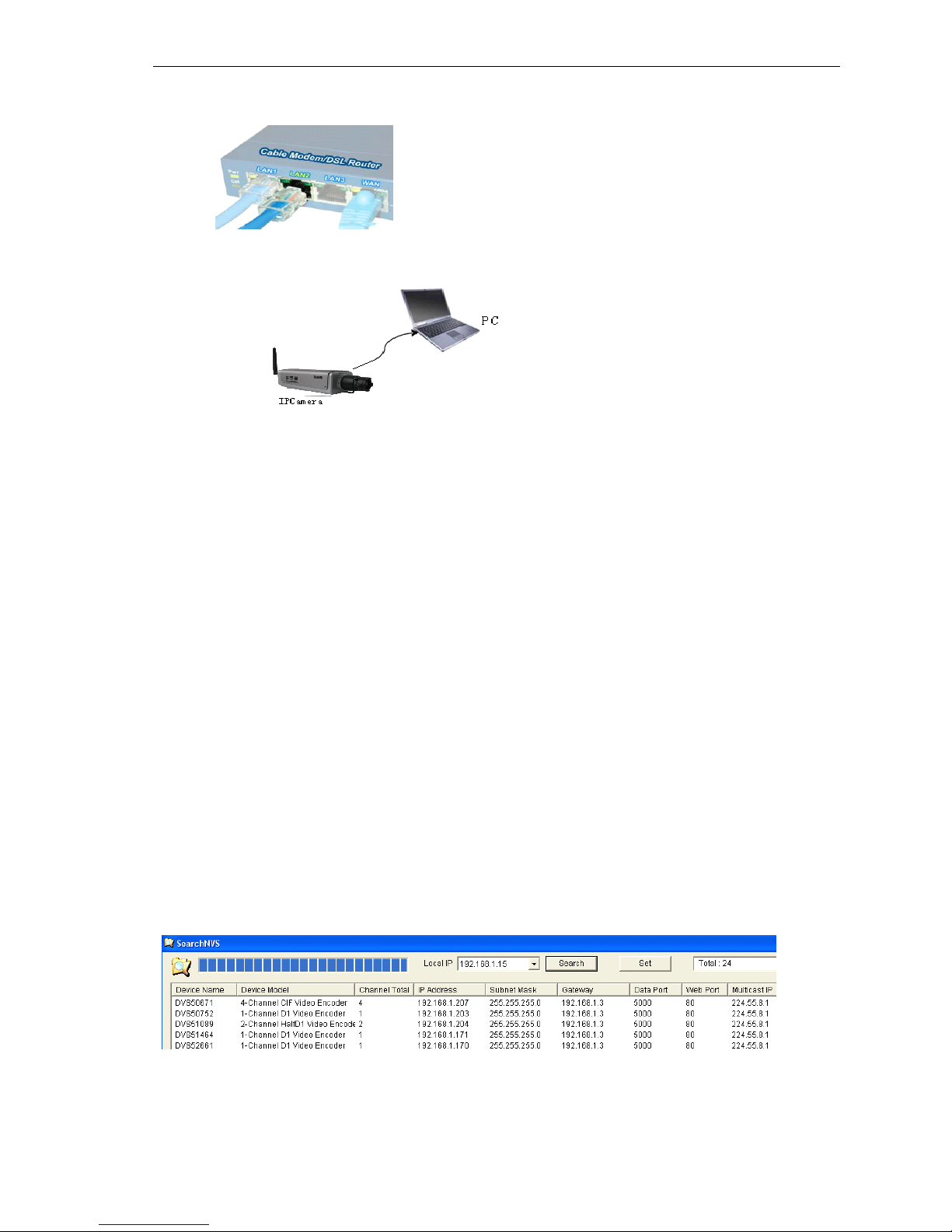
Step1: Connect power supply (DC 12V)
Step2: Connect LAN port with router/network switch/ hub via RJ45 cable.
2.2.2
2.2.2
2.2.2
2.2.2 Connect
Connect
Connect
Connect LAN
LAN
LAN
LAN port
port
port
port with
with
with
with PC
PC
PC
PC via
via
via
via RJ45
RJ45
RJ45
RJ45 cable.
cable.
cable.
cable.
The Light of LAN port turns green within 5 seconds under the normal network situation after power
on.
3
3
3
3 Searching
Searching
Searching
Searching device
device
device
device and
and
and
and installing
installing
installing
installing ActiveX
ActiveX
ActiveX
ActiveX
3.1
3.1
3.1
3.1 Searching
Searching
Searching
Searching device
device
device
device and
and
and
and modify
modify
modify
modify network
network
network
network parameters
parameters
parameters
parameters
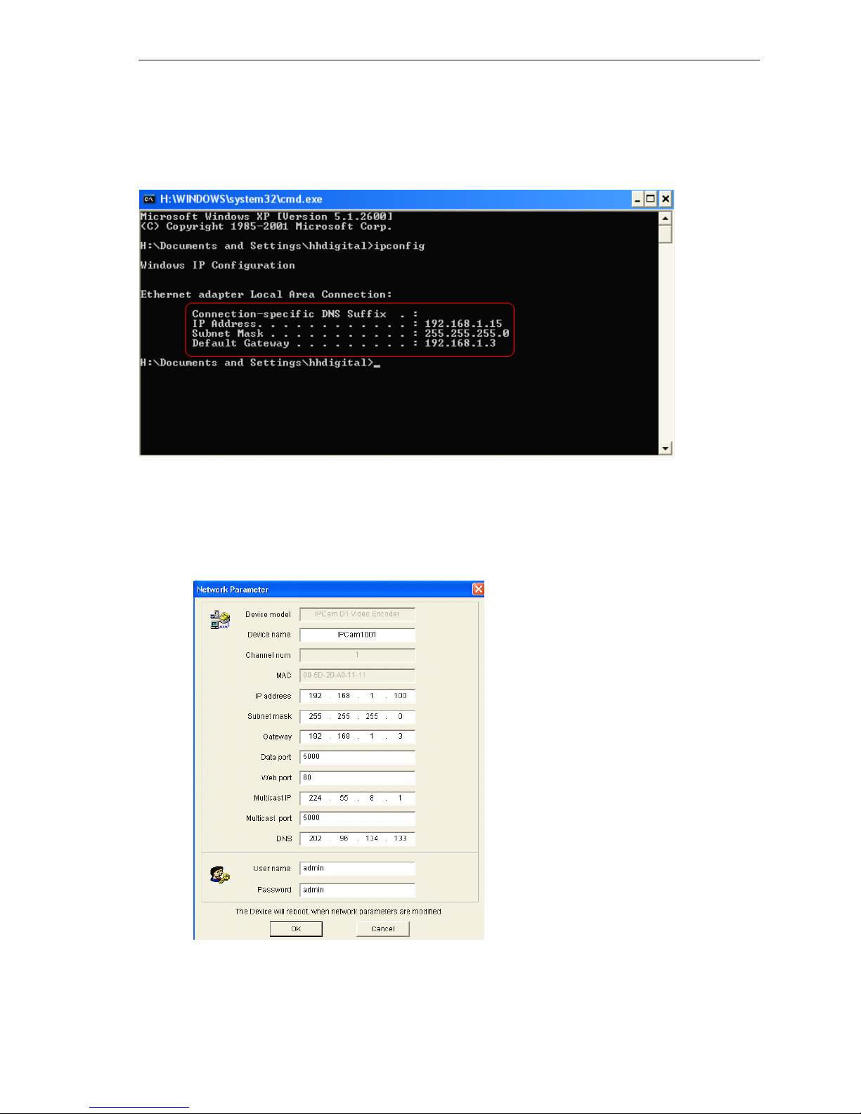
Run “ SearchNVS ”tofind the default IP and modify mega pixel ip camera network parameters
according
to
clients’local PC IP gateway (Such as IP address, subnet mask, gateway and
so
on)
How
to
run “ SearchNVS ” ,
A: Find the NVSCenter software in 【 Application 】 file from the CD.
B: Install the NVSCenter software, then do it as follows
to
find SearchNVS: 【 Start 】 --- 【 all
programs 】 --- 【 NVS Center 】 --- 【 Search NVS 】 .
�
�
�
�
Note
Note
Note
Note :
1.
The factory settings of the IP Camera as follows IP: 192.168.55.160; Subnet mask:
255.255.255.0.
2.
User name: admin; Password: admin
3.
Run the SearchNVS software
to
search and modify IP Camera network parameters .It is
multicast protocol. But the firewall forbids the multicast data packet. So please close the firewall
first.
(1)Click
(1)Click
(1)Click
(1)Click 【 SearchNVS
SearchNVS
SearchNVS
SearchNVS 】 button
button
button
button to
to
to
to run
run
run
run SearchNVS
SearchNVS
SearchNVS
SearchNVS software
software
software
software as
as
as
as follow:
follow:
follow:
follow:
【 Local IP 】 Display the local PC
IP.
If your PC is NIC or multi-addressed local
IP,
please select on
e
IP address
to
connect NVS.
Page 8
7 / 36
(2)Set IP address for mega pixel ip camera.
Your mega pixel ip gateway must be same as your local PC ’ s gateway. Then you can
visit IP camera. So we need to set the IP address for the IP camera before using 。
To
get your local PC IP configuration information: click “
start
” , choose “
run
” , then input
“
command
” or “
cmd
” (Windows
2000/XP
system).click “ confirm ” , then input “ ipconfig ” and
press “ Enter ” button, you will get following information:
Now please remember the above IP Address, Subnet Mask, Default Gateway , then set
the IP address of mega pixel ip camera according to your local PC IP address. For example
:192.168. 1 .100.
Please make sure the Default Gateway and Subnet Mask to be same.
Click 【 Set 】 to get the following windows:
After setting, click “
OK
” , then mega pixel IP camera will restart.
Page 9
8 / 36
3.2
3.2
3.2
3.2 Checking
Checking
Checking
Checking connection
connection
connection
connection
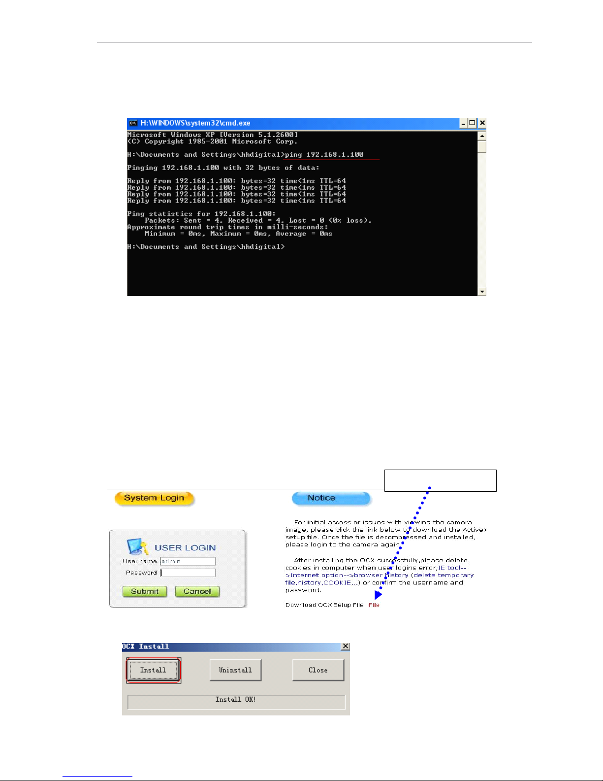
To
check connection works well: “ Start ”→ “ Run ”→ “ cmd ” .
Input: “ ping 192.168.1.100 ” , Click “ Enter ” button.
That means the IP Camera works normally and connects
to
network correctly .
[ Then use SearchNVS software
to
search and modify network parameters (such as IP address,
subnet mask, gateway and
so
on according
to
clients’local IP information ) ].
3.3
3.3
3.3
3.3 Installing
Installing
Installing
Installing ActiveX
ActiveX
ActiveX
ActiveX and
and
and
and login
login
login
login device
device
device
device
You
need
to
install ActiveX when you visit mega pixel IP camera for the first time through Internet
Explorer.
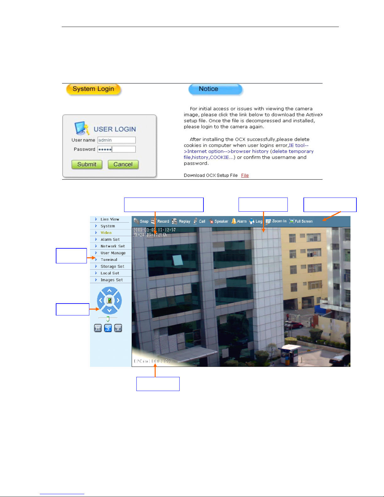
How to install ActiveX:
Download the ActiveX from Internet Explore: input the IP address of mega pixel IP camera
in Internet Explore; it appears Login interface as follows:
Click 【 File 】 to download the ActiveX
A new dialogue box pops up, click 【 Run
】
or 【 Save
】
to download ActiveX, after downl oad
it , double-click the downloaded file “ xdview.exe ” to install it as follows:
Download ActiveX
Page 10
9 / 36
Note: ActiveX have to be installed.
Close current Internet Explorer, click “ Install ” button,it will be installed the ActiveX and shows “ Insta ll
OK ! ” .
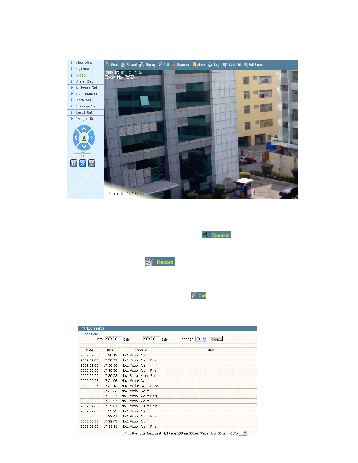
Open one Internet Explorer, and input IP address of IP Camera , for
example:192.168.55.160, it will show:
Input User name (Default: admin) 、 Password (Default: admin) , click “ Submit ” to show as
follows:
Video Name
Image display
Date,Time, Frame, Bitrate
Pan/Tilt
Function Keys
Setings
Page 11
10 / 36
4.
4.
4.
4. Software
Software
Software
Software configuration
configuration
configuration
configuration for
for
for
for mega
mega
mega
mega pixel
pixel
pixel
pixel IP
IP
IP
IP Camera
Camera
Camera
Camera
4.1
4.1
4.1
4.1 Liveview
Liveview
Liveview
Liveview
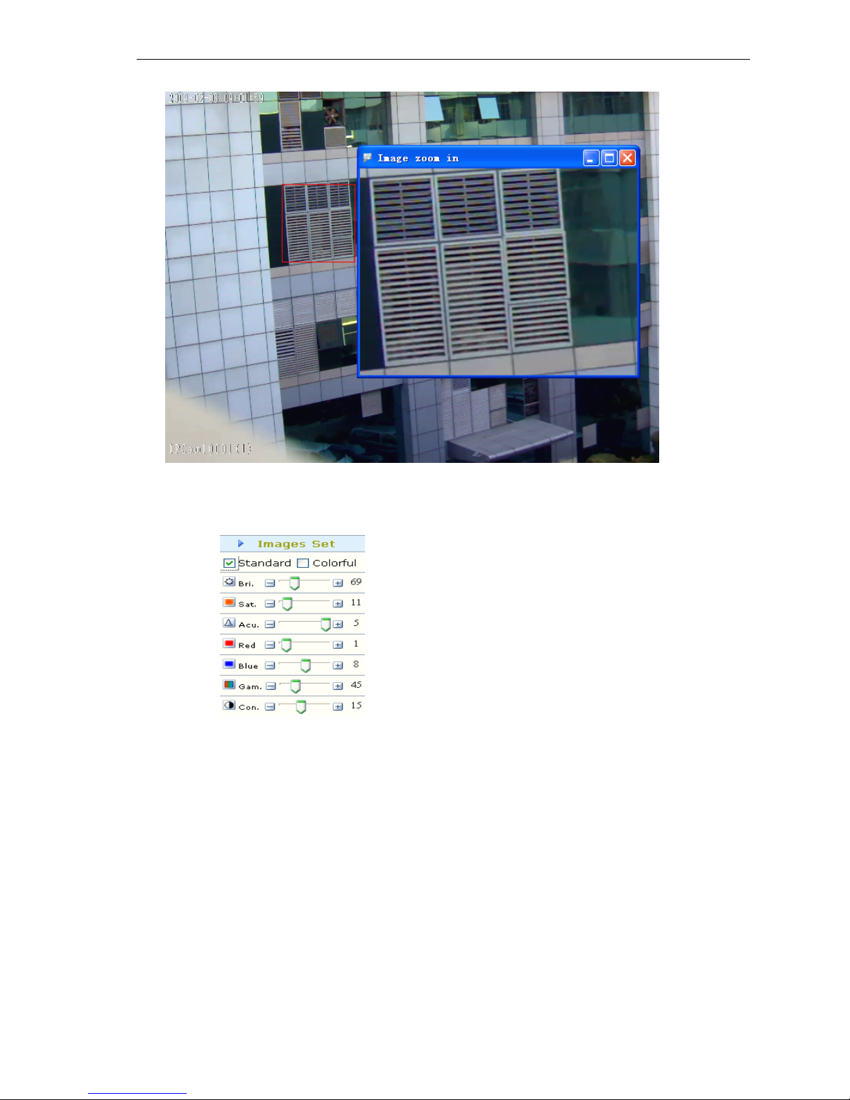
In the Liveview interface, User can do the operations as snap, record, replay, call, and
speaker, cancel alarm, check log, digital zoom in, full screen, P/T control, and video
parameters and image Set.
【 Speaker
Speaker
Speaker
Speaker 】 Audio Switch , The working status as :
【 Snap
Snap
Snap
Snap 】 click “ Snap ” , snap the current image ,it can be stored in your computer as JPG format.
【 Record
Record
Record
Record 】 Manual image recording, the current image can be stored in your computer as .MP6
format. The working status as:
【 Replay
Replay
Replay
Replay 】 click “ Replay ” , it will appear a new dialogue box, user can replay the image recorded or
picture captured.
【 Call
Call
Call
Call】Audio Switch,If user connects Microphone and Speaker with IP camera, it can do t he
two - way a udio function. The working status as:
【 Alarm
Alarm
Alarm
Alarm 】 When there is an alarm , double-click 【 Alarm 】
to
cancel the alarm manually .
【 Pan
Pan
Pan
Pan control
control
control
control 】 up, down, left, right, Automatic, level and vertical Operation
【 Log
Log
Log
Log 】 some alarm messages in Log as follows.(max 512 messages) :
Page 12
11
/ 36
【 Zoom
Zoom
Zoom
Zoom In
In
In
In 】 it has digital zoom in on the video as follows.
【 Full
Full
Full
Full Screen
Screen
Screen
Screen 】 full screen for display.
Mega pixel IP Camera: brightness, saturation, acutance, red, blue, gamma, contrast as
follows :
Page 13
12 / 36
4.2
4.2
4.2
4.2 Playback
Playback
Playback
Playback
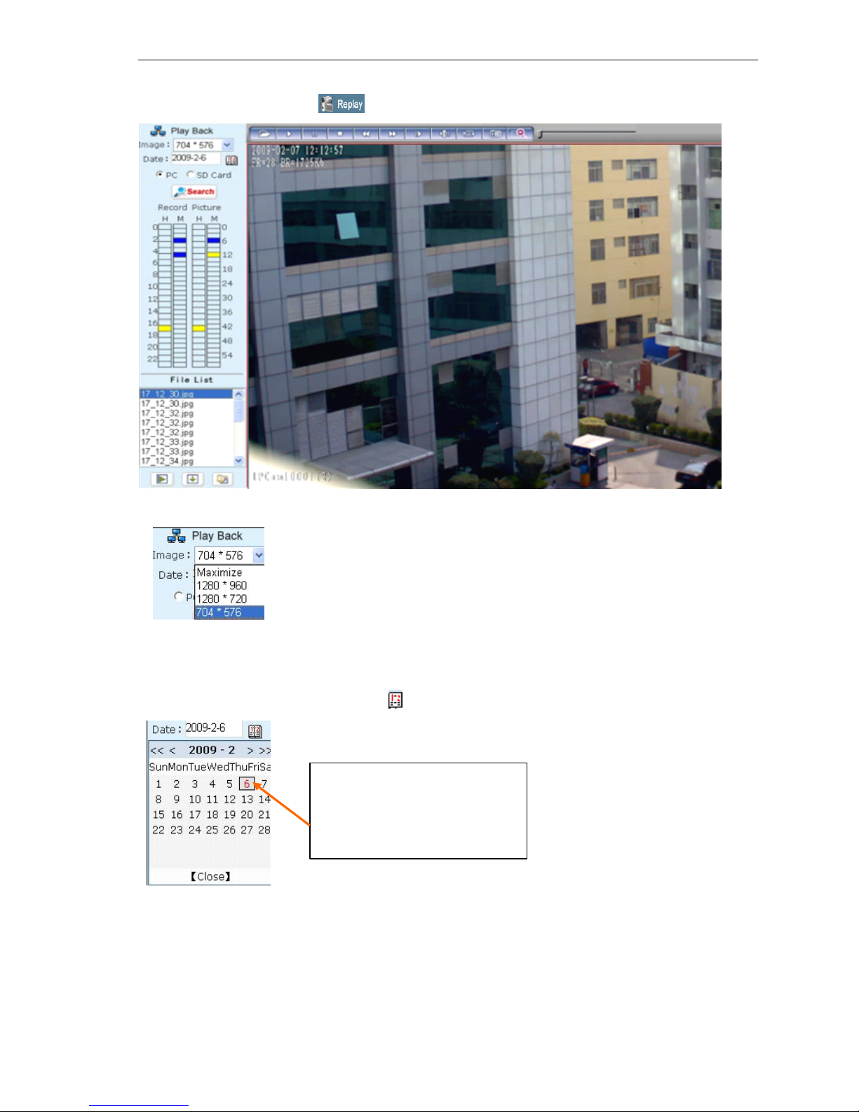
Click 【 Replay 】 button as: , then it appears the following interface:
User can select the resolution when replaying.
User can search the recorded image files or snapped pictures in local PC or SD card
according to date.
【 Date 】 User can check the recorded image files or snapped pictures according to the
appointed date, click the button as : It appears:
【 PC 】 check the recorded image files or snapped pictures in local PC according
to
the appointed
date.
【 SD Card 】 check the recorded image files or snapped pictures in SD Card according
to
the
appointed date.
【 File List 】 Shows the current recorded image files or snapped pictures in the File List.
Click “ 《 ” icon to previous year
Click “ 》 ” icon to next year
Click “ 〈 ” icon to previous month
Click “ 〉 ” icon to next month
Page 14
13 / 36
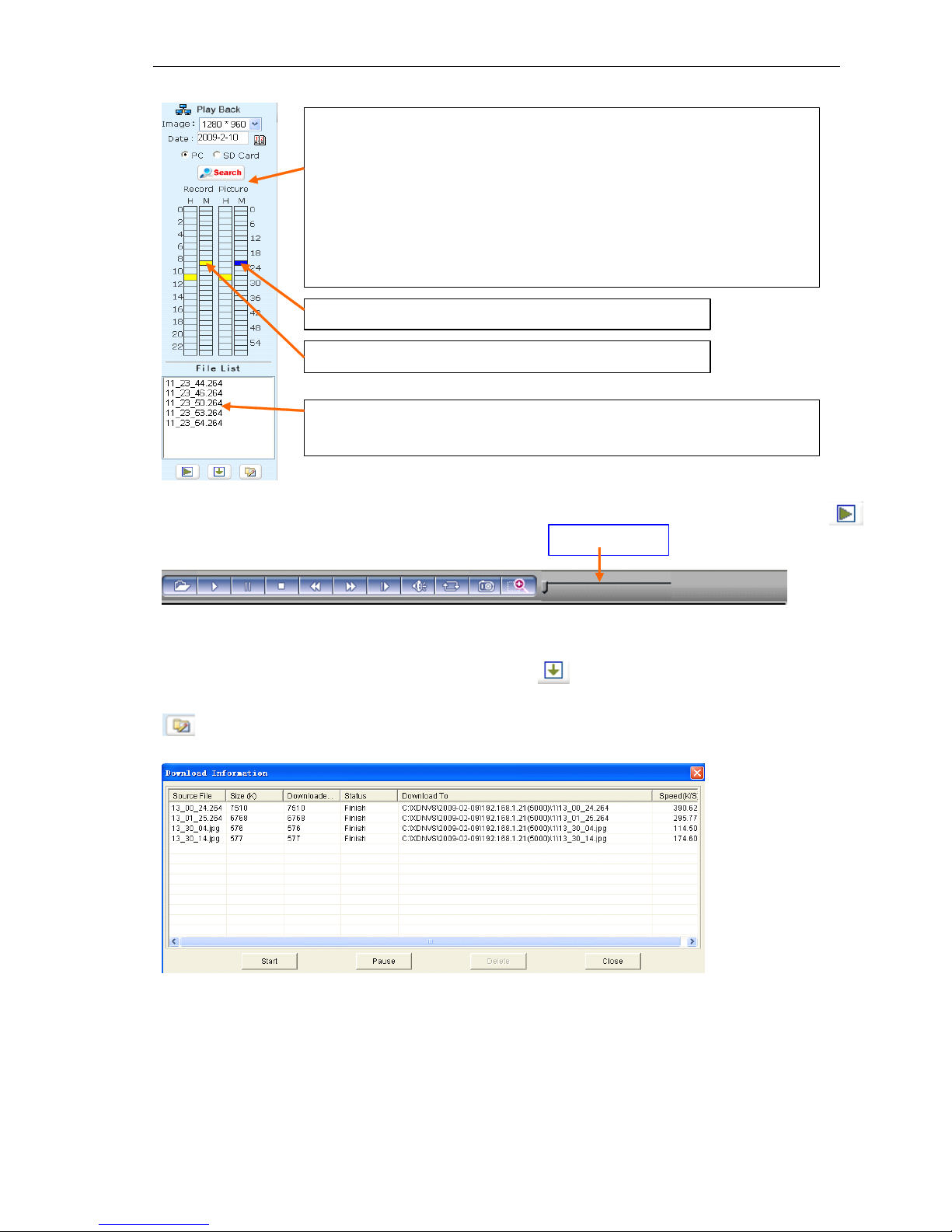
Check the current recorded image files or snapped pictures in the list as follows:
【 Play】Select the recorded image or snapped picture in play list, then click “ play ” button as :
【 Download 】 Searching the recorded image file or snapped pictures which downloaded fro m
SD card in Play list, click the “ Download ” button as to download it to local PC.
【 Download information】User will get the following information when click the “ Download ” as
Click 【 Pause 】 to pause download by manually , click 【 Start 】 to continue to download the
unfinished file,click
【 Delete】to del the downloaded file,click
【 Close】to close the downl oad
information interface.
There are two Lists: Record & Pic ture :
Record List means the recorded image in PC on Feb 10 , 200 9
Pic List means the snapped picture in PC on Feb 10 , 200 9
The left of the Record / Pic List is Hour unit (from 0 to 23)
The right of the Record / Pic List is Minute unit (from 0 to 59)
The yellow icon means the image recorded / picture snapped in the current selected time.
The blue icon means the image recorded / picture snapped in the selected time.
This blue icon means the picture snapped at 11:23 on Feb 10, 2009.
The yellow icon means the image recorded at 11:23 on Feb 10, 2009.
These files were named by the recorded time. For example: the file 1 1 _ 23 _ 5 0. 264 means
this image recorded at 1 1 : 23 : 50 ' .
Time Table
Page 15
14 / 36
4.3
4.3
4.3
4.3 System
System
System
System
System
System
System
System Settings
Settings
Settings
Settings as
as
as
as follows
follows
follows
follows :
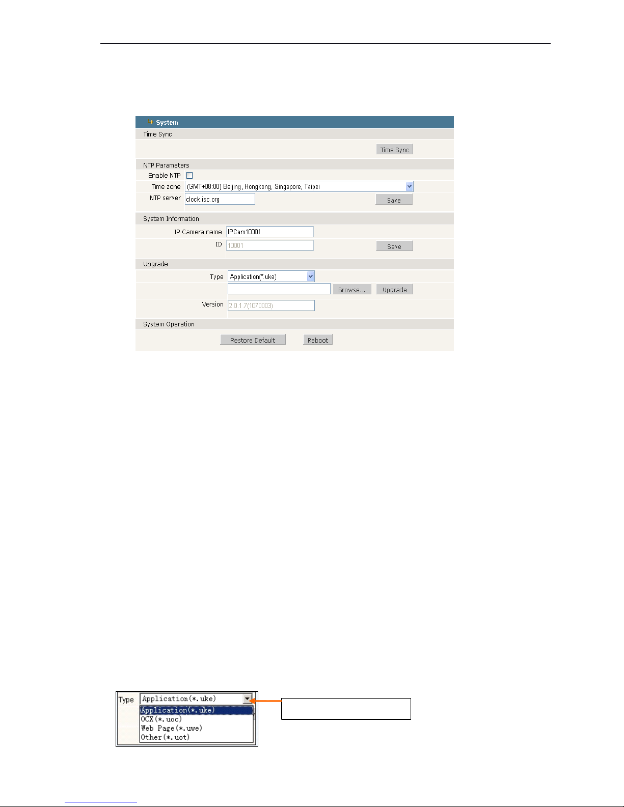
Mega pixel IP camera system set
【 Time Sync】click: “ Time Sync ”,The system time of the device will be synchronous with comput er .
【 NTP Parameter 】 Please input the correct NTP server address and select the correct time zone.
After save it, switch
to
【 Real-time Image】,The NTP sever will show the correct system tim e.
【 System Information 】 Display device name, device number and user-defined device name.
Note : R ename the device name and save it, the device will restart.
【 System Information 】 display the camera name and number message, the name can be
defined by user, and CCD camera can select PAL or NTSC.
【 Upgrade 】 User can upgrade the uke,uoc,uwe in IE.
【 Restore Default】Resume all the IP Camera parameters (Including Network parameter except M AC
address)
to
default factory settings.
Note:
Note:
Note:
Note: Be careful when use this function.
【 Reboot 】 Click 【 Reboot 】 , the IP Camera will restart after 5 seconds.
Upgrade:
Check the following steps before upgrade :
1,Check the IP camera version, User can upgrade the version in IE, and user has
to
upgrade three
files , the sequence of the upgrade as follows:
Step1: Application (uke)
Step2: OCX (uoc)
Step3: Web Page (uwe)
2 , Check the type of upgrade file as follows:
Select type of upgrade
Page 16
15 / 36
Note:
(1)
please upgrade IP camera according
to
the order, first upgrade the version (uke) , Then OCX file
and Web Page file
(2)
Don ’ t interrupt the power and internet during the upgrading IP camera.
(3)
P lease check the new version is the right one.
4.4
4.4
4.4
4.4 Video
Video
Video
Video
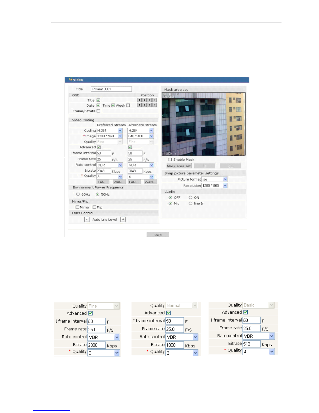
( 1 ) Mega pixel IP camera Video set
【 Title 】 rename the video name, displaying on the lower left corner .
【 OSD 】 display channel name, date, time, week and frame / bit rate.
【 Position Adjustment 】 move the OSD position on video .
【 Video Coding 】 set the preferred stream and alternate stream .
【 Coding 】 support H.264 and MJPEG ( MJPEG for mobile surveillance ) .
【 Image 】 set image resolution.
CMOS: support resolution (1600*120), (1280*960) and 1280*720.
【 Quality 】 Options for Fine, Normal, Basic
“ Fine ” , default “ N ormal ” default “ B asic ” default
,
Page 17
16 / 36
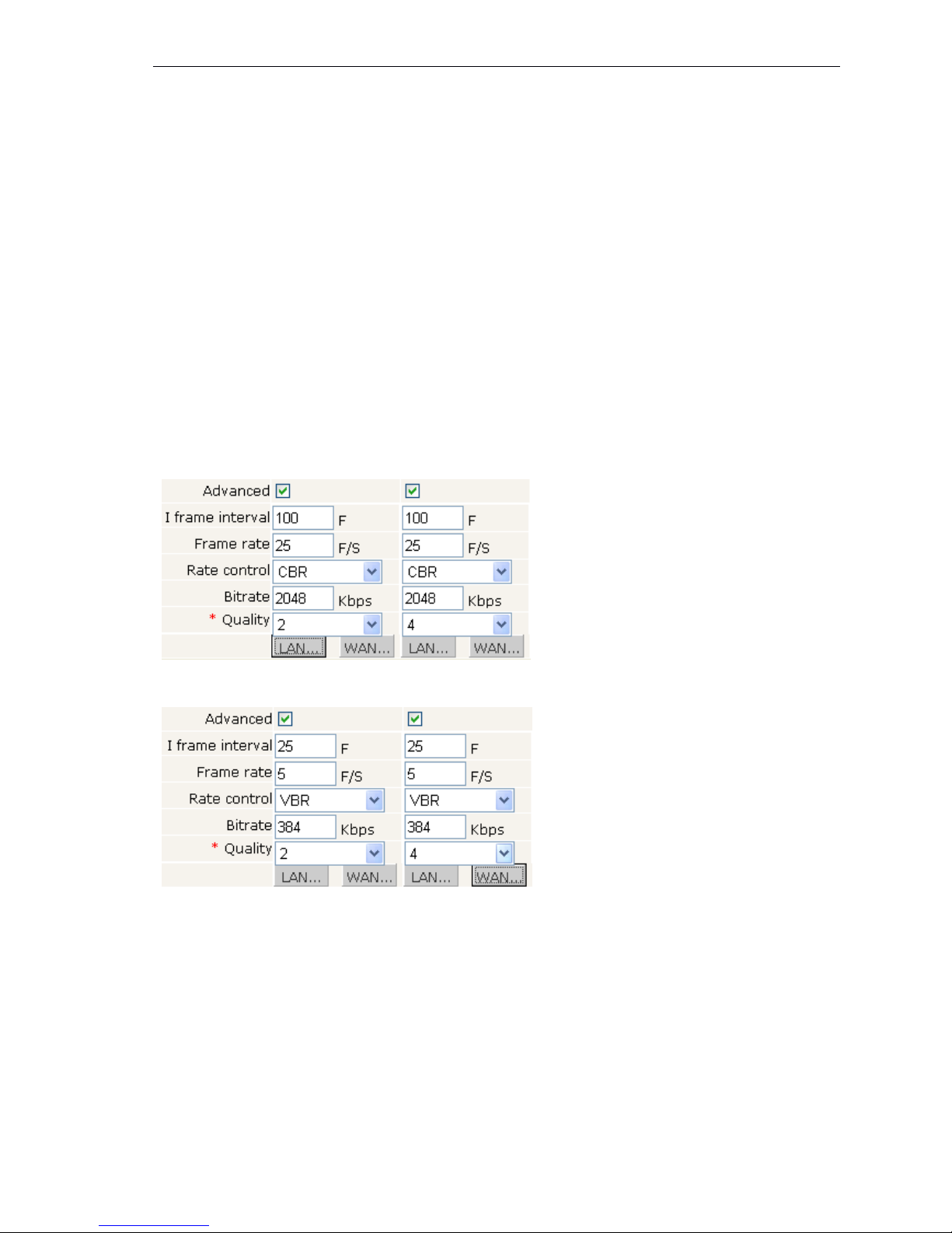
【 Advanced 】 select this option to set other parameters.
【 I frame interval 】 When the network bandwidth is not good, it is good way to increase the I
frame interval to make the image fluently. The range of I frame interval is 0 ~ 200.The
smaller I frame interval, better image quality. Normally, I frame interval is twice as frame
rate.
【 Quality 】 When the network bandwidth is not good, it is better to increase the number of
“ Quality ” . The smaller “ Quality ” , better image quality. Normally, Quality is 3-4.
【 Frame rate 】 frame/second ,
CMOS: when the resolution is 1600*1200, the frame rage: 0~15,
w hen the resolution is 1280*960, the frame range: 0~25
w hen the resolution is 1280*720, the frame range: 0~30
To set the frame rage according to the bandwidth situation, when the network bandwidth is
not good, it is good way to reduce the frame rage to make the image fluently.
【 Rate Control 】 Select VBR or CBR( VBR means V ariable Bit Rate, it is used for low bandwidth
situation; CBR means Constants Bit Rate, it is used for big bandwidth.
【 Bitrate 】 please set the bitrate according
to
your network bandwidth. Better image quality for
higher bitrate settings, but it needs more bandwidth
【 LAN 】 Default :
【 WAN 】 Default:
Note :
This options is for professional user to set
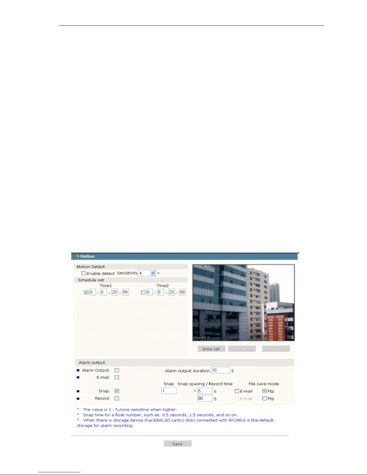
【 Enable Mask
】
Mask area set can be set all image or part image, the maximum 4 areas can be se t.
【 Snap picture parameter settings 】 set the picture format and resolution.
【 All 】 mask the whole image.
【 Clr 】 clear the mask
【 Audio】Set audio
ON/OFF
( Default: OFF),there are two models: Microphone and Line input. If users
don ’ t need audio status; please close audio inputtosave the DSP resource and network resource.
【 Power Frequency 】 Environment power frequency of the device, if it is not correct, the
image will flicker.
【 Video Mirror 】 Image enantiomorphism switch
Page 18
17 / 36
【 Video Flip 】 Image reversal switch
After setting, click the 【 save 】 button.
4.5
4.5
4.5
4.5 Motion
Motion
Motion
Motion alarm
alarm
alarm
alarm
Motion alarm set :
Page 19
18 / 36
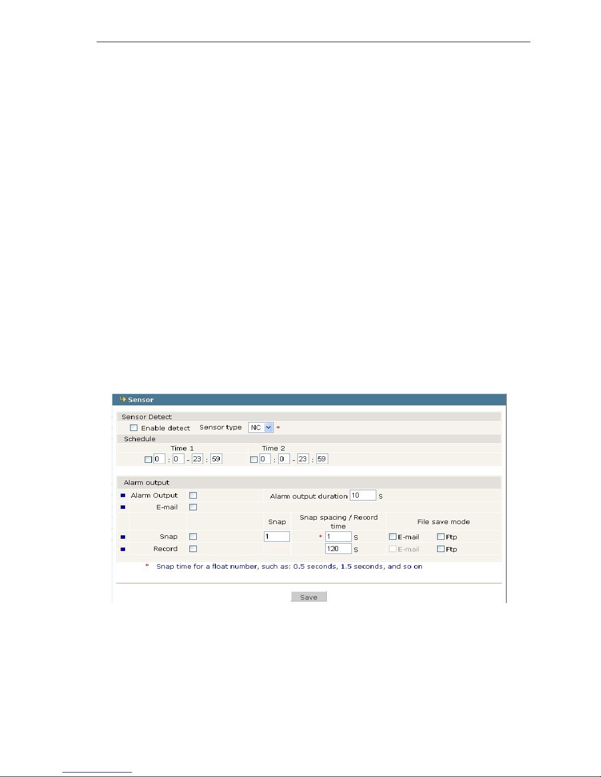
Motion alarm set: included schedule time, switch of the alarm, sensitivity, alarm output, alarm
record or alarm snap sending by FTP .And snap sending by email. (Default storage SD card without
selecting email or FTP)
【 Schedule Set 】 set the two schedule times for motion alarm detection.
【 Alarm output 】 alarm signal output.
【 Alarm output duration 】 set the time from 0~86400 seconds.
【 Email 】 send alarm message by email.
【 Snap 】 set alarm snapped picture sending by email or FTP. If there are continuous alarms, the
interval time of capturing is the duration time.1 snapped picture per 1 second.
【 Record 】 set alarm record sending by FTP
【 Area set 】 Press the left button of mouse and drag
to
the detected area. Four areas can be set.
【 All 】 Set whole area as detected area
【 Clr 】 Clear all detected area.
After setting, click the 【 save 】 button.
4.6
4.6
4.6
4.6 Sensor
Sensor
Sensor
Sensor alarm
alarm
alarm
alarm
Sensor
Sensor
Sensor
Sensor alarm
alarm
alarm
alarm set
set
set
set :
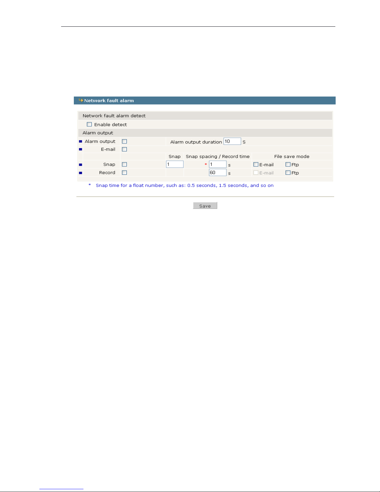
Sensors alarm set: included schedule time, switch of the alarm, sensitivity, alarm output, alarm
record or alarm snap sending by FTP .And snap sending by email. (Default storage SD card without
selecting email or FTP)
【 Schedule Set 】 set the two schedule times for motion alarm detection.
【 Alarm output 】 alarm signal output
【 Alarm output duration 】 set the time from 0~86400 seconds.
【 Email 】 send alarm message by email.
【 Snap 】 set alarm snapped picture sending by email or FTP. If there are continuous alarms, the
Page 20
19 / 36
interval time of capturing is the duration time.1 snapped picture per 1 second.
【 Record 】 set alarm record sending by FTP.
After setting, click the 【 save 】 button.
4.7
4.7
4.7
4.7 Network
Network
Network
Network fault
fault
fault
fault alarm
alarm
alarm
alarm
Network
Network
Network
Network fault
fault
fault
fault alarm
alarm
alarm
alarm :
Network fault alarm set: included schedule detecting time, switch of the alarm, sensitivity, alarm
output duration , alarm record or alarm snap sending by FTP .And snap sending by email. (Default
storage SD card without selecting email or FTP)
【 Enable detect 】 detect network fault.
【 Alarm output 】 alarm signal output
【 Alarm output duration 】 set the time from 0~86400 seconds.
【 Email 】 send alarm message by email.
【 Snap 】 set alarm snapped picture sending by email or FTP. If there are continuous alarms, the
interval time of snapping is the duration time.1 snapped picture per 1 second.
【 Record 】 recording 1 minute.
Note:
Note:
Note:
Note: Email and FTP can ’ t work when network fault happens. When the network works,
the snapped picture or recorded file will be sent by email and FTP again.
After setting, click the 【 save 】 button.
4.8
4.8
4.8
4.8 Network
Network
Network
Network
Network
Network
Network
Network Set
Set
Set
Set :
Page 21
20 / 36
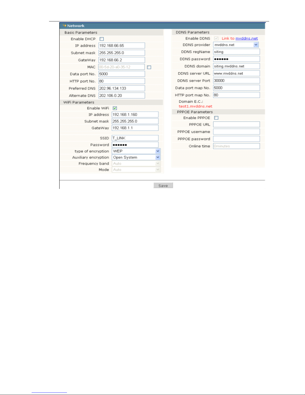
Set IP address, Subnet mask, Gateway, MAC, Data port, HTTP port, DNS address. The device
will restart after setting the basic parameters and saving. If it is in LAN, the IP address can ’ t be same
as LAN computers’IP.
Wifi Setting.
It is suitable for wireless network environment. For examples,
a
wireless router, TP-Link WR340G
54M, firstly login the wireless routertocheck some WIFI information. Then set the mega pixel ip
camera WIFI: SSID and password.
【 Enable WIFI 】 Open the WIFI function
【 IP address 】 Logging on wireless network (wireless router /AP), for example: 192.168.1.2
【 Gateway 】 Wireless network gateway (wireless router/AP), for example: 192.168.1.1
【 SSID number 】 It is the user name of certificate for wireless network. User can login on wireless
network after checking the validation. This SSID number must be same as the SSID number of the
wireless network (wireless router/AP).Save the parameters after setting. Then Pull out the cable,
visit IP camera through wireless
IP,
for example 192.168.1.2.
Note
Note
Note
Note :
1) The Gateway of wireless network can ’ t be same as the Gateway of wired network .
2) When ip camera does not have the WiFi function, the WiFi setting disable
DDNS
DDNS
DDNS
DDNS Setting
Setting
Setting
Setting
Setting Dynamic Domain Name Servertobind
a
fixed Domain Name, the server will find the
device by the Domain Name no matter what the IP address changed.
【 DDNS User Name 】 User registered in DDNS server
【 DDNS Password 】 User Password in DDNS server.
【 DDNS Domain Name 】 The Domain Name set for long-distance controlling after user logon in
Page 22
21 / 36
DDNS server.
【 DDNS Address 】 When the DDNS address is the domain Name, please set the DNS address
correctly.
Note:
Note:
Note:
Note:
The default DNS address is Guangdong China DNS address. If users are in other
regions to use DDNS function, please set the correct DNS address for the device same as
the user local DNS address.
【 DDNS Port 】 Default :30000.
【 Data Port Forwarding 】 When the device mapped
to
TCP/IP through network server, fill in the
TCP/IP data port forwarding number.
【 WEB Port Forwarding No 】 When the device mapped
to
TCP/IP through network server, fill in the
TCP/IP WEB port forwarding number.
PPPOE:
PPPOE:
PPPOE:
PPPOE:
Dial-up setting, open PPPOE
to
set PPPOE User name, Password (get it from network
supplier), It can login on WAN
After setting, click 【 Save 】 button
4.9
4.9
4.9
4.9 Advanced
Advanced
Advanced
Advanced
Advanced set
set
set
set :
Mail
Mail
Mail
Mail Setting
Setting
Setting
Setting
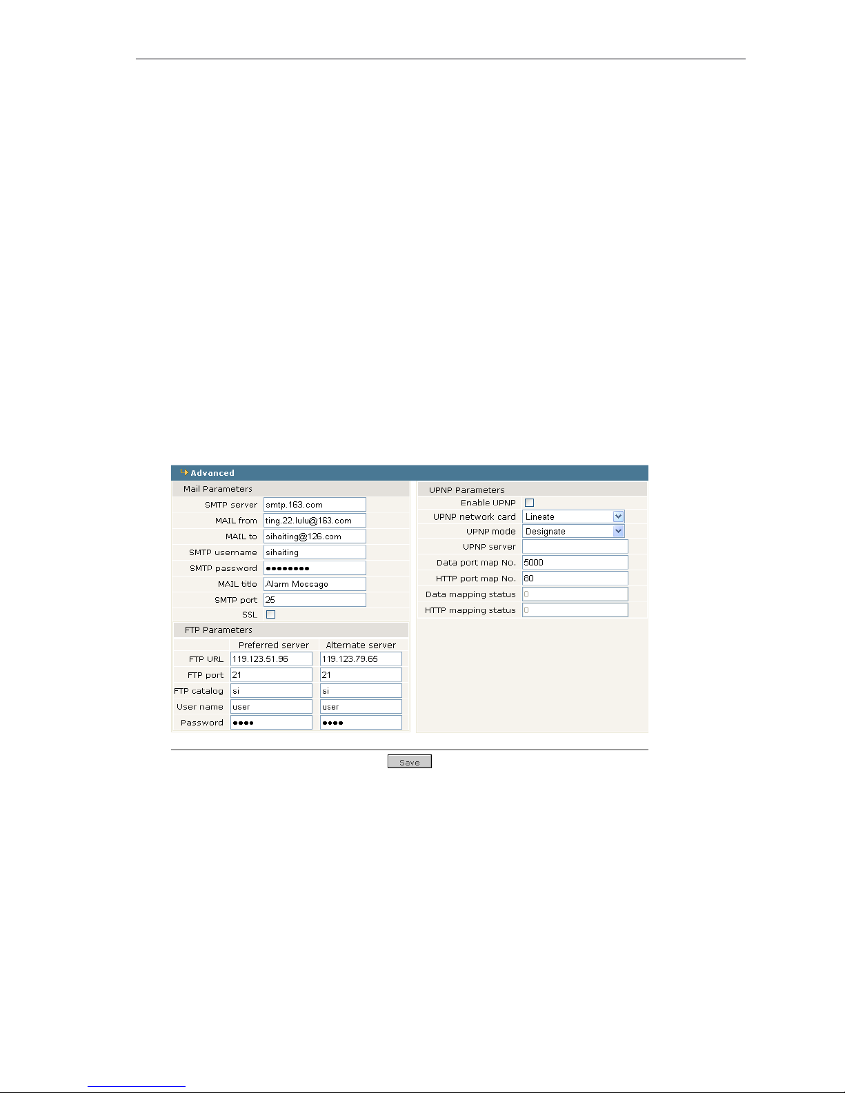
When there is a motion alarm, the device will send the alarm mail to the designated email box
automatically
【 SMTP Server】Email server address, different emails has their different Email server address , f or
example:163 mail, the SMTP server is smtp.163.com 。
【 Mail From 】 sending alarm mail from this email box.
【 Mail To 】 receiving alarm mail from this email box.
【 SMTP User Name 】 User Name for sending mail box.
【 SMTP Password 】 Password for sending mail box
【 Mail Title 】 Title for the alarm mail.
【 Motion Alarm
】
Select this option, mail function success. When there is a motion alarm, the devi ce
will send the alarm mail to the designated email box automatically.
【 Sensor alarm
】
Select this option, mail function success. When there is a sensor alarm, the devi ce
Page 23
22 / 36
will send the alarm mail to the designated email box automatically .
【 Snap picture 】 When there is a motion alarm or a sensor alarm, the device will snap the picture
and storage it on the local PC.
FTP
FTP
FTP
FTP Setting
Setting
Setting
Setting
The Snap picture can be transferred
to
the FTP server which is assigned.
【 Schedule
Schedule
Schedule
Schedule Send
Send
Send
Send 】 start schedule send, User can set the interval time.
【 Schedule
Schedule
Schedule
Schedule Send
Send
Send
Send Time
Time
Time
Time 】 Send schedule time.
【 FTP
FTP
FTP
FTP URL
URL
URL
URL 】 FTP server IP address or HTTP.
【 FTP
FTP
FTP
FTP Port
Port
Port
Port 】 FTP server port , default port is 21.
【 FTP
FTP
FTP
FTP Username
Username
Username
Username and
and
and
and Password
Password
Password
Password 】 FTP server Username and Password
UPNP
UPNP
UPNP
UPNP Setting
Setting
Setting
Setting
Port forwarding automatically: when there is server with UPNP function in LAN, open this
function and the server will map the set port to TCP/IP automatically .
【 UPNP Network Card 】 The model of network card in UPNP server.
【 UPNP mode 】 There are designate and automate modes :
The designate mode is that the data port forwarding No and web port forwarding No were
designated to Server.
The automate mode is that the server sets the data port forwarding No and web port forwarding
No.
【 UPNP server 】 Gateway address of network server with UPNP function.
After setting, click the 【 save 】 button.
4.10
4.10
4.10
4.10 User
User
User
User management
management
management
management
User
User
User
User management
management
management
management set:
set:
set:
set:
Page 24
23 / 36
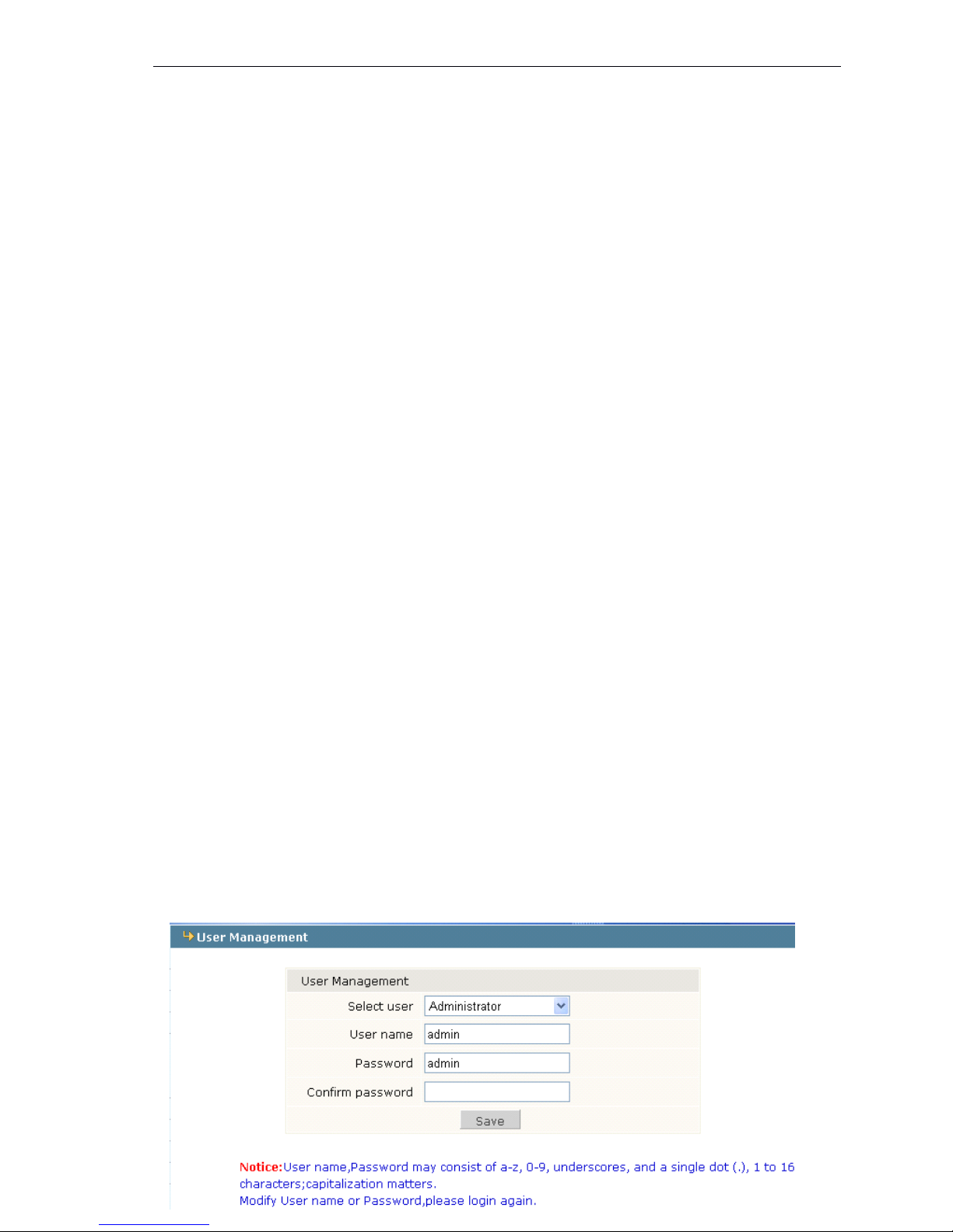
You
can set t hree users for one IP Camera. One user is Administrator and other s are Guest.
Administrator can set parameters for the IP Camera. However, Guest cannot set parameter s .
Note:
Note:
Note:
Note:
User name can be composed of letters, numbers, underline or dot between 1 and 16
characters. Pay attention to the capitals and small letters .
4.11
4.11
4.11
4.11 Terminal
Terminal
Terminal
Terminal
Terminal
Terminal
Terminal
Terminal set:
set:
set:
set:
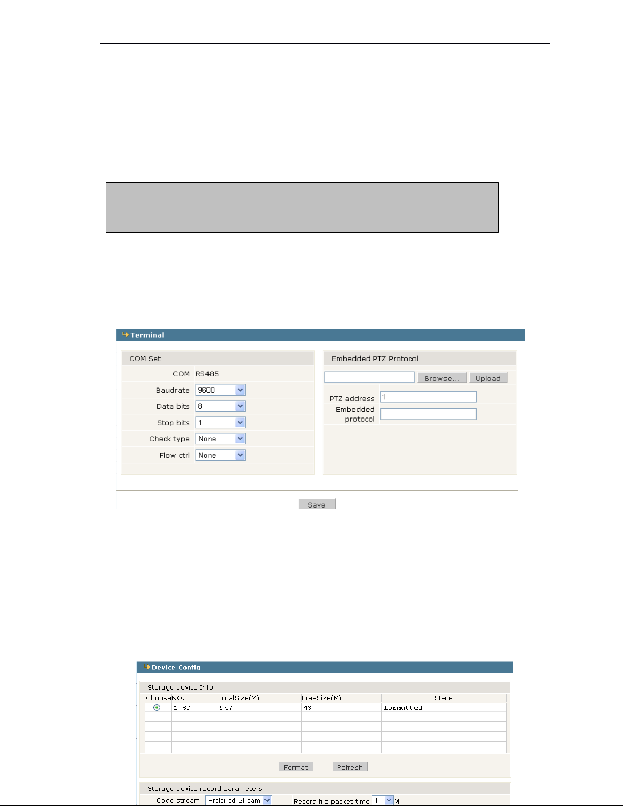
Pan /Tilt Decoder connect with RS485 port. When there is control device
to
connect with IP Camera,
RS485 parameters need
to
be set according
to
the settings of the control device (Address, Protocol,
Bit rate), and download the corresponding protocol.
click the 【 save 】 button after setting .
4.12
4.12
4.12
4.12 Storage
Storage
Storage
Storage set
set
set
set
4
4
4
4 .
.
.
. 12
12
12
12 .
.
.
. 1
1
1
1 There
There
There
There is
is
is
is Device
Device
Device
Device Config
Config
Config
Config ,
,
,
, Record
Record
Record
Record set
set
set
set and
and
and
and Snap
Snap
Snap
Snap set
set
set
set in
in
in
in Storage
Storage
Storage
Storage set.
set.
set.
set.
The
The
The
The device
device
device
device set
set
set
set as
as
as
as follows:
follows:
follows:
follows:
Default Administrator Name: admin password: admin
Default Guest Name: user1 \ user 2 password: user1 \ user 2
Note: Pay attention to match capitals and small letters to User name and password
Page 25
24 / 36
Check the SD information: Total size, free size and format SD card.
【 Code stream
】
set the code stream when recording, it can be selected preferred strea m
or alternate stream ; the packet time for recorded file is the time of image recording.
【 other parameters 】 when there is no space for recording, the files recorded one hour
ago will delete automatically. If the recorded file is not enough one hour, the device
will stop recording and snapping.
Auto search the storage device when start, this is test the storage device , recommend
unchecked
4
4
4
4 .
.
.
. 12
12
12
12 .
.
.
. 2
2
2
2 Record
Record
Record
Record schedule:
schedule:
schedule:
schedule:
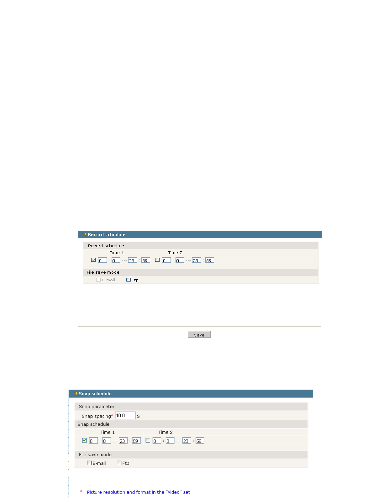
Set schedule time for record ing and save it. When select the FTP, the recorded file will be
sent to FTP server. Otherwise, it will be stored in SD card. ( Note: when users select FTP
sending, it needs SD card in the device. Otherwise, it is only three images in the flash. And
the new ones will overwrite the old ones )
4
4
4
4 .
.
.
. 12
12
12
12 .3
.3
.3
.3 Snap
Snap
Snap
Snap schedule
schedule
schedule
schedule :
Page 26
25 / 36
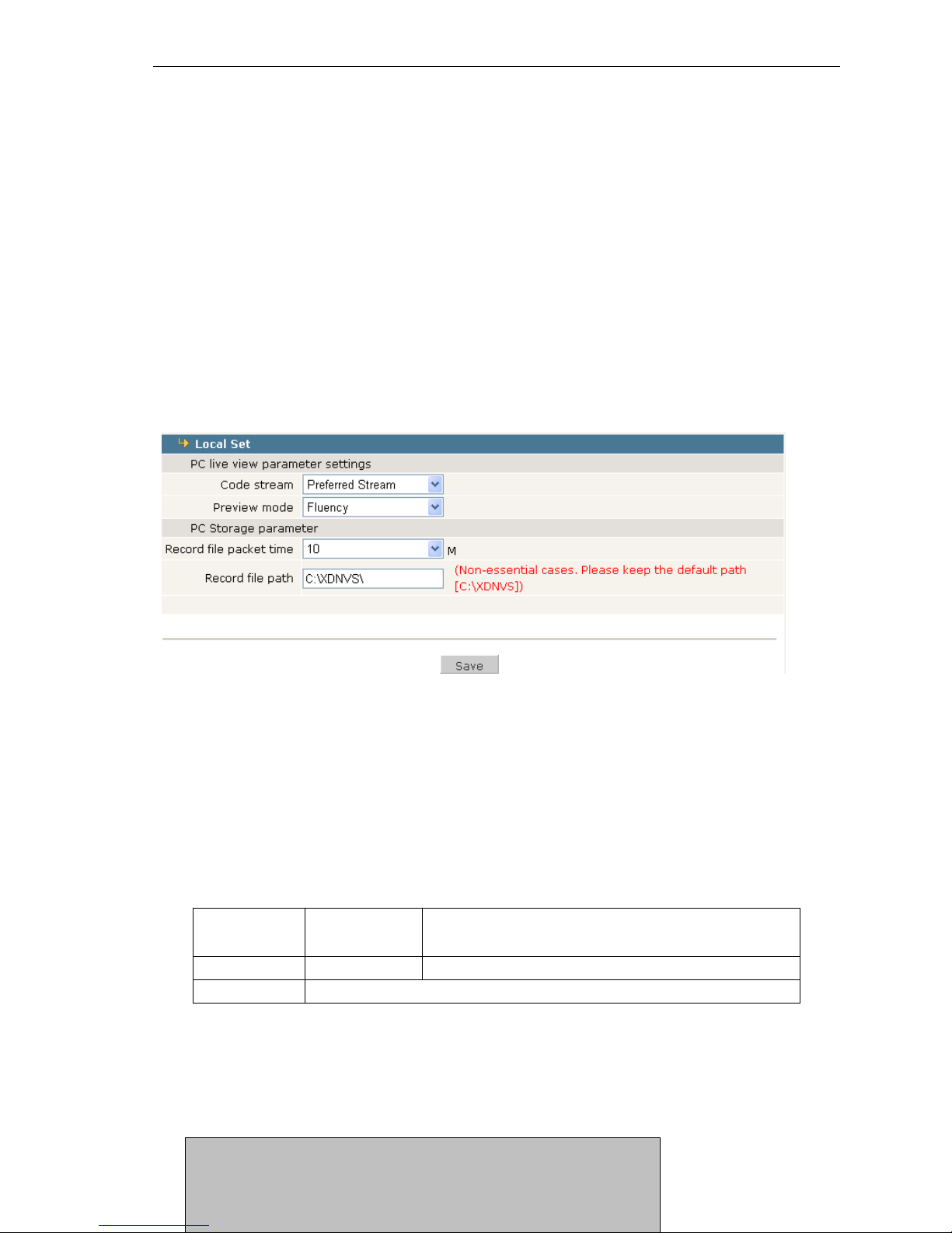
Set schedule time for snapping: When it starts the sending by email or FTP, the time
interval should be more than 0.3 second. If users don ’ t select the FTP and email, and the
device without SD, it will stop the snapping schedule.
Note : the picture resolution can be set in “ Video set ” .
4.13
4.13
4.13
4.13 Local
Local
Local
Local set
set
set
set
Local
Local
Local
Local set
set
set
set :
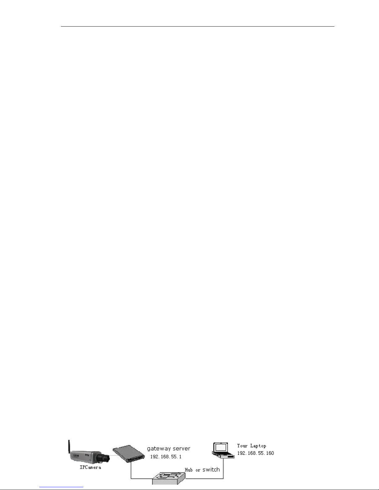
【 Code stream 】 select Preferred Stream or Alternate Stream as liveview.
【 Preview mode 】 select real-time or Fluency.
【 Record file packet time 】 The packet time can be set as 1,5,10,15,20,25,30,60minutes.
【 Record/Snap save to 】 The local storage for record and snap, the default is C : \XDNVS.
Appendix
Appendix
Appendix
Appendix 1
1
1
1 Network
Network
Network
Network Interface
Interface
Interface
Interface for
for
for
for IP
IP
IP
IP Camera
Camera
Camera
Camera
Network
Network
Network
Network port
port
port
port of
of
of
of IP
IP
IP
IP Camera:
Camera:
Camera:
Camera:
Appendix
Appendix
Appendix
Appendix 2
2
2
2 Network
Network
Network
Network Parameters
Parameters
Parameters
Parameters Default
Default
Default
Default
Network
Network
Network
Network parameters
parameters
parameters
parameters default
default
default
default
TCP
80(Web port)
5000(Communication port, Audio/Video data
transmitting Port,
Talk
data transmitting Port)
UDP
5000
Audio/Video data transmitting Port
Multiple port
Multiple original port + Channel Number
Wired network parameters default :
IP Address: 192.168.55.160 Data port: 5000
Subnet Mask: 255.255.255.0 Web port : 80
Gateway: 192.168.55.1 DHCP
:
OFF
Page 27
26 / 36
Appendix
Appendix
Appendix
Appendix 3
3
3
3 Visits
Visits
Visits
Visits IP
IP
IP
IP Camera
Camera
Camera
Camera under
under
under
under different
different
different
different network
network
network
network environment
environment
environment
environment
You
can use your laptop or PC
to
connect the IP camera through LAN or Internet, the following will
show you how
to
use IP Camera under the different network environment.
1
1
1
1 、 LAN
LAN
LAN
LAN
There are two ways to connect the IP camera in the LAN: Static local IP and dynamic local IP
�
�
�
�
Static
Static
Static
Static local
local
local
local IP
IP
IP
IP
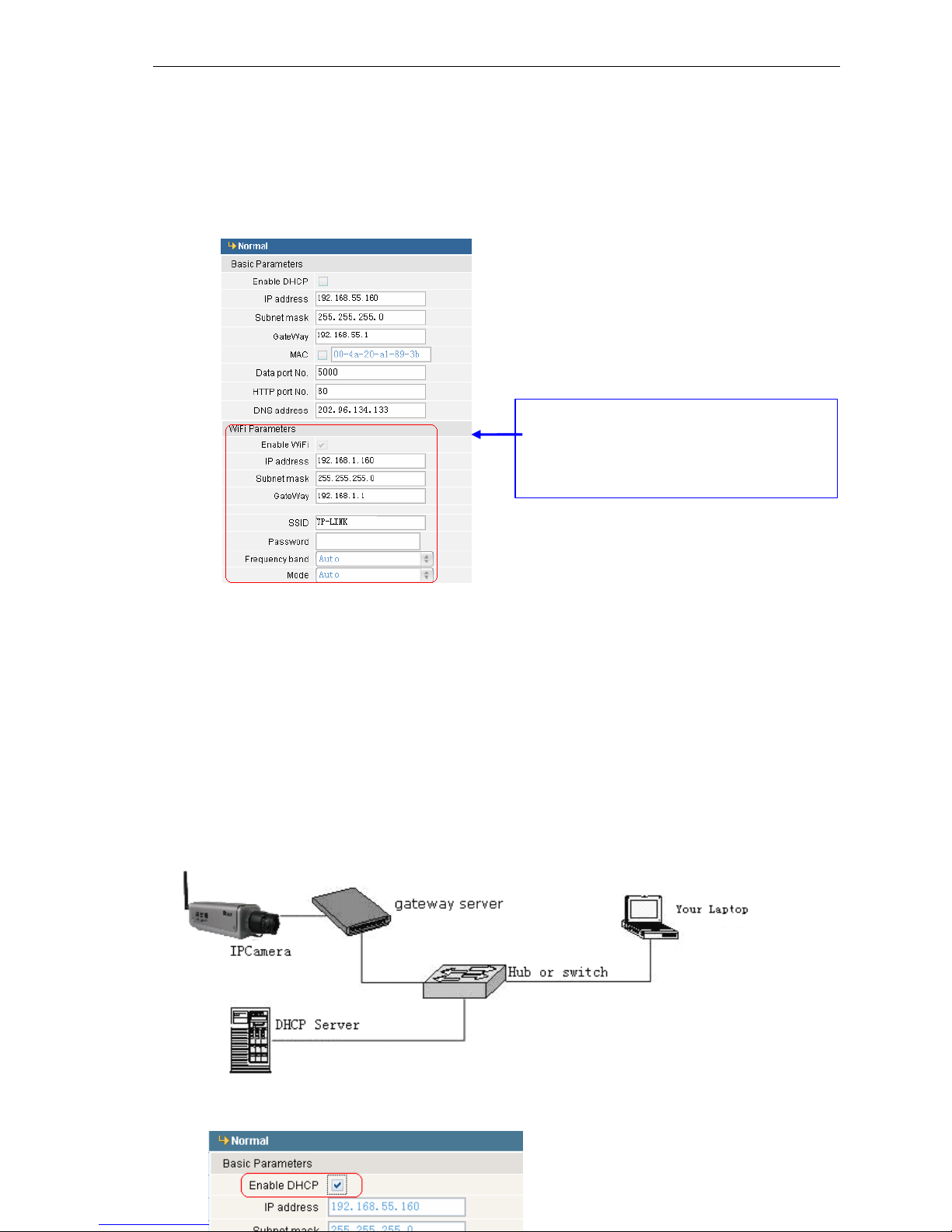
Static local IP: refertoyour network administrator assign ed local IP address.
The lin k ing drawing as the following :
Page 28
27 / 36
The network setting please checks the following:
Setting
Setting
Setting
Setting Step
Step
Step
Step :
One : Login IP camera via the IE browser.
Two : Fills local IP address which the network administrator assigns, for example: 192.168.55. 1 6 0
;
Three : Fills subnet mask , for example : 255.255.255.0 ;
Four : Fills gateway address , for example : 192.168.55.1 ;
Finished the parameter, clicks 【 Save 】
to
restart IP camera.
�
�
�
�
Dynamic
Dynamic
Dynamic
Dynamic local
local
local
local IP
IP
IP
IP
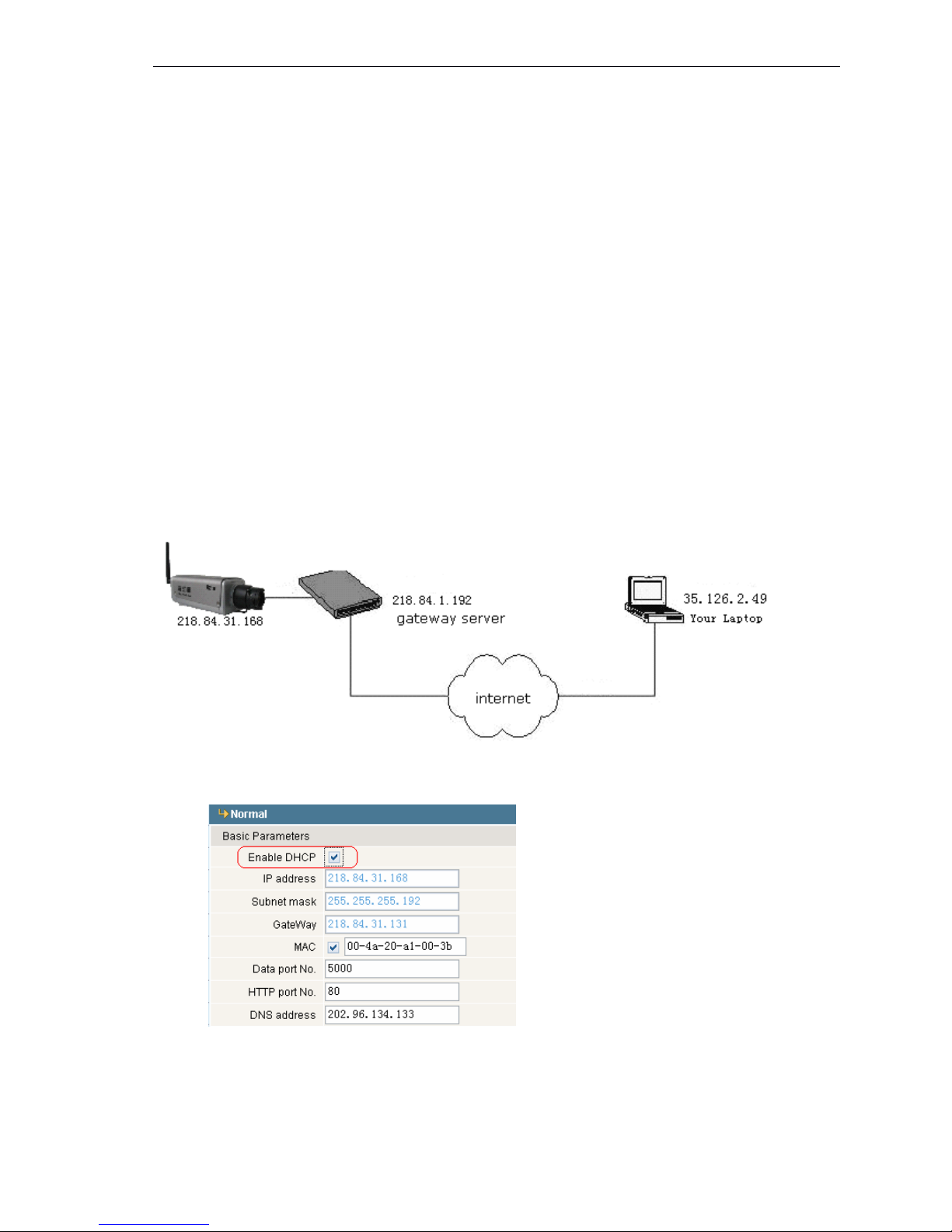
Dynamic IP refers
to
the IP camera
to
obtain the IP address in the identical local area network
through the DHCP server. The linking drawing as the following :
The network setting please check the following :
If you have an IP camera with WiFi, you
have to set the IP address, the subnet mask
and gateway address in" WiFi parameters ”
according to your wireless router.
Page 29
28 / 36
Users login IP camera via the IE browser, set [network] and [DHCP] parameters, after
settings clicks [Save]torestart IP camera then the settings become effective.
2
2
2
2 、 Internet
Internet
Internet
Internet
You
can connect the IP camera with Internet through three ways: Fixed IP mode, ADSL and
router sharing accesses the internet mode, ADSL and IP camera ’ s PPPoE accesses the internet
mode. After IP cameras connect with the Internet, user can visit the camera on WAN via dynamic
domain name or the IP address (static IP with port forwarding form) directly.
�
�
�
� Fixed
Fixed
Fixed
Fixed IP
IP
IP
IP Mode
Mode
Mode
Mode
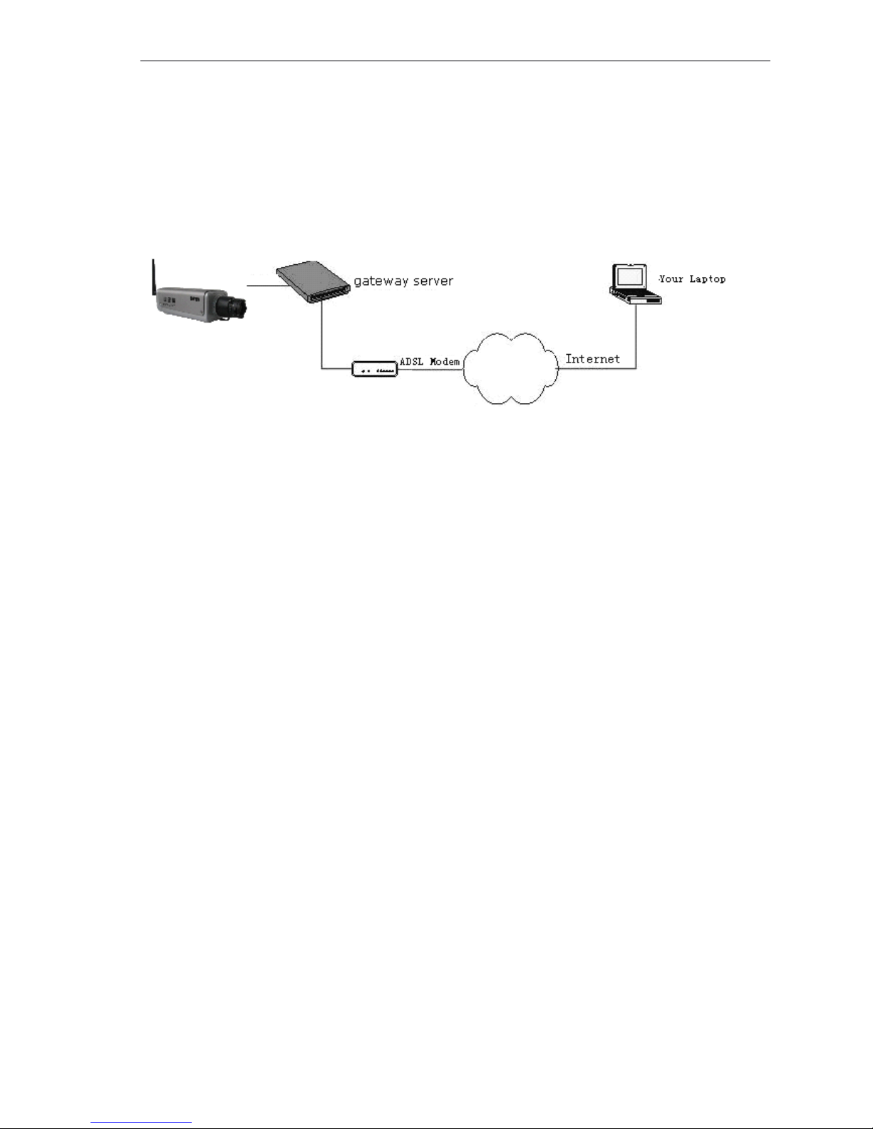
The linking drawing as the following :
The
The
The
The network
network
network
network setting
setting
setting
setting please
please
please
please check
check
check
check the
the
the
the following
following
following
following :
Step:
Step:
Step:
Step:
One : Login IP camera via IE browser, and change 【 network 】 setting ;
Two : Input the IP address which applies from the network server,
for example : 218.84.31.168 ;
Page 30
29 / 36
Three : Input the correct subnet mask , for example : 255.255.255.192 ;
Four : Input the correct gateway address , for example : 218.84.31.131 ;
After setting , click 【 Save 】
to
restart IP camera.
�
�
�
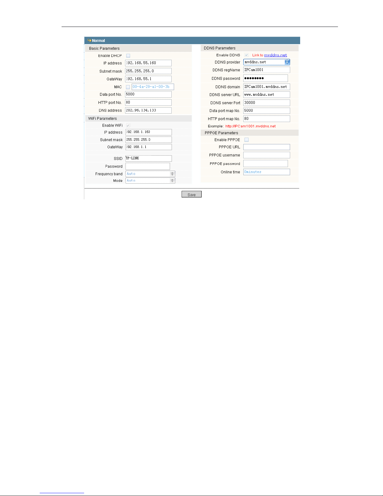
� ADSL and router sharing accesses the internet mode .
The
The
The
The linking
linking
linking
linking drawing
drawing
drawing
drawing as
as
as
as the
the
the
the following
following
following
following :
Input the username and password which applies in the DDNS server on the DDNS setting items
,
makes the port forwarding on the router. User can visit the camera on WAN via dynamic domain
name directly. The network setting please check the following :
Page 31
30 / 36
Step
Step
Step
Step :
:
:
:
One: login DDNS
server
( i.e.http://www.mvddns.net),Register username and password. ( The
operation please refer to Appendix
Appendix
Appendix
Appendix 3
3
3
3 )
Two : Click to open DDNS ;
Three : Choose DDNS server, for example:http://www.mvddns.net ;
Four : Input the Registration name ;
Five : Input the Registration password ;
Page 32
31 / 36
Six : Input domain name address which applies
to
the DDNS server ,
for example:test.mvddns.net ;
Seven: Input the DDNS IP address, for example www.mvddns.net ;
Eight : Input the DDNS server port, default port:30000 ;
Nine : Input the public data port No. which assign via port forwarding , default port:5000,
Ten : Input the public WEB port No. w hich assign via port forwarding , default port: 80
After setting, click [Save]torestart IP camera .
�
�
�
� ADSL
ADSL
ADSL
ADSL and
and
and
and IP
IP
IP
IP camera
camera
camera
camera
’
’
’
’
s
s
s
s PPPoE
PPPoE
PPPoE
PPPoE accesses
accesses
accesses
accesses the
the
the
the internet
internet
internet
internet mode
mode
mode
mode
The
The
The
The linking
linking
linking
linking drawing
drawing
drawing
drawing as
as
as
as the
the
the
the following
following
following
following :
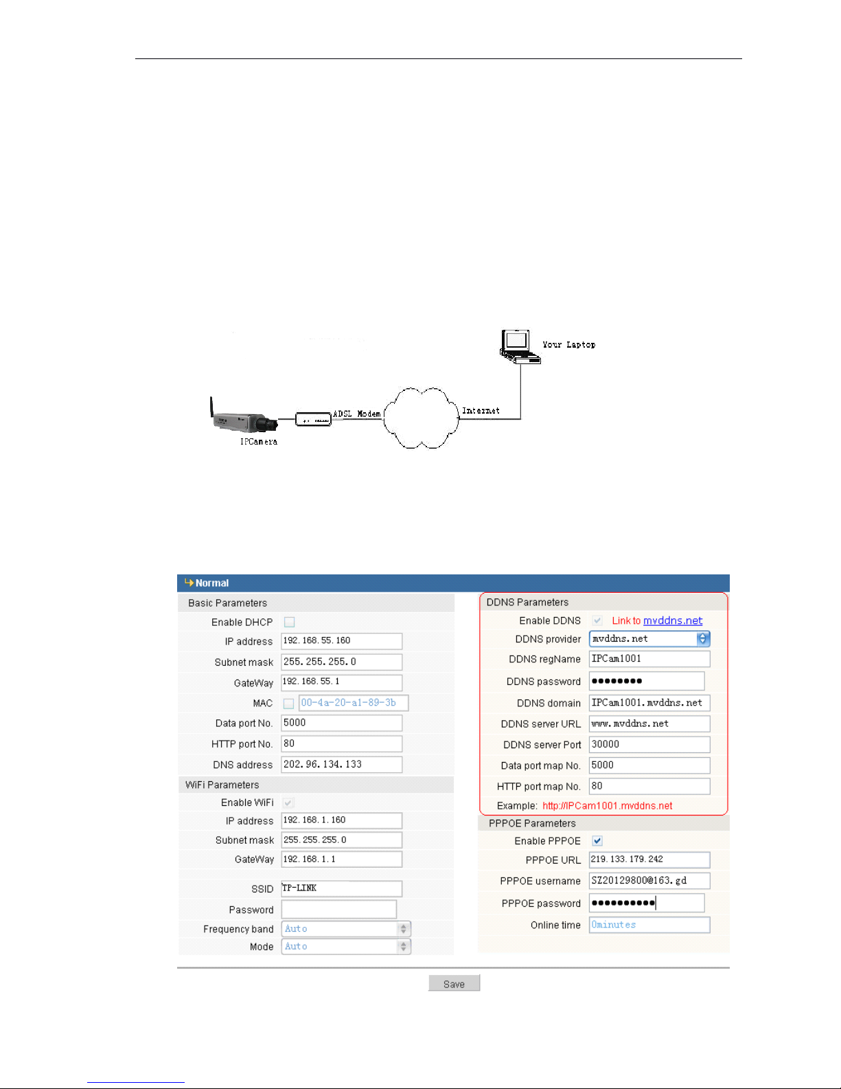
Input the username and password which applies in the DDNS server on the DDNS setting
items, then Input the PPPoE username and password which applies from network provider on the
PPPoE setting item.
The
The
The
The network
network
network
network setting
setting
setting
setting please
please
please
please check
check
check
check the
the
the
the following
following
following
following :
The DDNS parameter settings are same as above, the PPPoE setting must input the correct
Page 33

32 / 36
PPPoE username and password which applies from the network provider.
Ap
Ap
Ap
Ap pendix
pendix
pendix
pendix 4
4
4
4 FAQ
FAQ
FAQ
FAQ
(
(
(
( 1
1
1
1 Forget
Forget
Forget
Forget Password
Password
Password
Password
Answer:
Answer:
Answer:
Answer: 【 RESET 】 on the IP Camera back, press it
to
retrieve all parameter
to
default (Factory
Setting). The default user name: admin, password: admin
(2
(2
(2
(2 No
No
No
No image
image
image
image in
in
in
in IE
IE
IE
IE Browser
Browser
Browser
Browser
Reason
Reason
Reason
Reason : Uninstall ActiveX.
Answer
Answer
Answer
Answer :
You
need
to
install ActiveX Control when you visit IP Camera for the first time.
Click “ file ”
to
d ownload ocx. A new dialogue box appears, click 【 Run
】
or 【 Save
】
to dow nload
ActiveX, after download it , double-click the downloaded file “ xdview.exe ” to install ActiveX
and shows “ Install OK! ”
(3
(3
(3
(3 Why
Why
Why
Why failed
failed
failed
failed to
to
to
to log
log
log
log i
i
i
i n
n
n
n IP
IP
IP
IP Camera
Camera
Camera
Camera after
after
after
after upgrade
upgrade
upgrade
upgrade through
through
through
through IE
IE
IE
IE Browser?
Browser?
Browser?
Browser?
Answer:
Answer:
Answer:
Answer: Delete the cooks of IE. Method: find the tool of browser---Internet options---Internet
temporary file---click “ delete file ” button , choose the option ” delete all offline contents ” . Confirm and
restarttolog i n IP Camera.
(4
(4
(4
(4 Why
Why
Why
Why the
the
the
the image
image
image
image is
is
is
is not
not
not
not fluent?
fluent?
fluent?
fluent?
Reason
Reason
Reason
Reason 1:
1:
1:
1: The video frame rate is low
Answer:
Answer:
Answer:
Answer: Improve the video frame rate
Reason
Reason
Reason
Reason 2:
2:
2:
2: Many users view the image
Answer:
Answer:
Answer:
Answer: Close some clients or reduce the video frame rate.
Reason
Reason
Reason
Reason 3:
3:
3:
3: The bandwidth is too low.
Answer:
Answer:
Answer:
Answer: Reduce the video frame rate or video compression bit rate
6,
6,
6,
6, Can
Can
Can
Can ’
’
’
’ t
t
t
t visit
visit
visit
visit IP
IP
IP
IP Camera
Camera
Camera
Camera via
via
via
via IE
IE
IE
IE browser?
browser?
browser?
browser?
Page 34
33 / 36
Reason
Reason
Reason
Reason 1:
1:
1:
1: Internet offline.
Answer:
Answer:
Answer:
Answer: If it is an error of network connection, do the following steps: Connect PC
to
network
to
test
whether they work normally or not.
Reason
Reason
Reason
Reason 2:
2:
2:
2: IP Address was occupied by other device.
Answer:
Answer:
Answer:
Answer: Cut off the connection of IP Camera and network, connect IP Camera and PC, and then
set IP address again according
to
recommendatory operation.
Reason
Reason
Reason
Reason 3:
3:
3:
3: IP address lies in different subnet ?
Answer:
Answer:
Answer:
Answer: Check the IP and subnet mask, test the settings of gateway.
Reason
Reason
Reason
Reason 4:
4:
4:
4: The physical address of network conflict with IP Camera ?
Answer:
Answer:
Answer:
Answer: please modify the physical address of IP Camera.
Reason
Reason
Reason
Reason 5:
5:
5:
5: The web port is modified by others ?
Answer:
Answer:
Answer:
Answer: please contact administrators of networks
to
obtain relevant port information.
Reason
Reason
Reason
Reason 6:
6:
6:
6: When the causes can not found 。
Answer:
Answer:
Answer:
Answer: please res et IP Camera
to
default state, and connect IP Camera. (System default IP
address: 192.168.55.160; mask address: 255.255.255.0).
(7
(7
(7
(7 Speaker
Speaker
Speaker
Speaker without
without
without
without sound
sound
sound
sound
Reason
Reason
Reason
Reason 1:
1:
1:
1: Without connecting Audio input.
Answer:
Answer:
Answer:
Answer: Checking the Audio connection.
Reason
Reason
Reason
Reason 2:
2:
2:
2: Without choosing the option of Audio in IP Camera.
Answer:
Answer:
Answer:
Answer: Checking the Audio parameters of IP Camera, choosing the option of Audio.
(8
(8
(8
(8 The
The
The
The effect
effect
effect
effect of
of
of
of the
the
the
the audio
audio
audio
audio is
is
is
is not
not
not
not good.
good.
good.
good.
Reason:
Reason:
Reason:
Reason: When there are many noises for the Audio and the distortion is very serious, please check
the input signal level, if it is not lineate input, the signal level is not matching with the signal level of
IP Camera. And it results in the saturation distortion.
Answer:
Answer:
Answer:
Answer: please adopt the proper lineate input accord with the IP Camera
(9
(9
(9
(9 How
How
How
How to
to
to
to deal
deal
deal
deal with
with
with
with the
the
the
the image
image
image
image abnormal?
abnormal?
abnormal?
abnormal?
Reason
Reason
Reason
Reason 1:
1:
1:
1: Computer system problem, DirectX is off; image shows slowly and color is abnormal.
Reason
Reason
Reason
Reason 2:
2:
2:
2: Hardware problem , Graphic card can not support it; The image is speed up and
hardware Zoom function. ( It has
to
change the Graphic card for hardware problem )
Answer
Answer
Answer
Answer
:
:
:
:
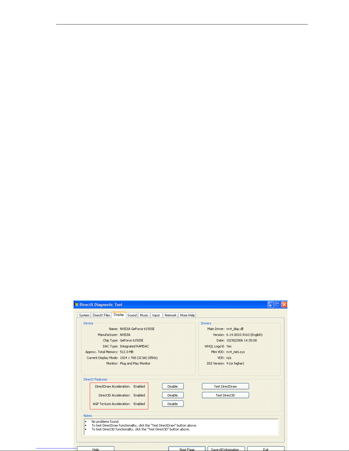
install DirectX image drive , Start Run input “ DXDIAG ” as follows:
Page 35

34 / 36
Note
Note
Note
Note:start DirectDraw speedup、Direct3D speedup、AGP veins speedup in DirectX functions。If they
can not be started, that means the DirectX installation failure or hardware no display.
( 10
10
10
10 Small
Small
Small
Small image
image
image
image size
size
size
size under
under
under
under the
the
the
the resolution
resolution
resolution
resolution 1600*1200
1600*1200
1600*1200
1600*1200 ?
Reason: The computer resolution caused
Answer: Change the computer resolution
to
big one.
 Loading...