

Page 1

ECOMASTER COMFORT
USER’S MANUAL
Ecomaster Comfort
Page 1 of 19
MH-020-00-Ecomaster comfort user's manual Edited 06/04
Page 2

Ecomaster Comfort
INDEX:
1. OPERATING DESCRIPTION.
1.1 Driver on/off switch for the air conditioning.
1.2 Driver temperature adjustment control.
1.3 Driver fan speed adjustment.
1.4 Driver recirculation baffle adjustment
1.5 Variation in the driver’s foot/windscreen baffles
1.6 Driver automatic air conditioning setting.
1.7 Passenger air conditioning on/off switch.
1.8 Passenger temperature adjustment.
1.9 Passenger evaporator fan speed.
1.10 Passenger recirculation baffle adjustment.
1.11 Passenger automatic air conditioning setting.
1.12 ECO option.
1.13 Timer programming.
1.14 Preheater.
1.14.1 Programmed mode.
1.14.2 Normal mode.
1.15 Viewing interior temperature.
1.16 Dehumidifier option.
1.17 Operation in Sleeping mode.
1.18 Screen contrast adjustment.
2. ERROR DETECTION AND INDICATION.
Page 2 of 19
MH-020-00-Ecomaster comfort user's manual Edited 06/04
Page 3

Ecomaster Comfort
1. OPERATING DESCRIPTION.
The Ecomaster Comfort front panel has three distinct areas:
Driver air conditioning functions
Common functions
Passenger air conditioning
functions
When reference is made to the driver air conditioning functions, the key named will be
the one in that area, with a similar shape to that for passengers.
1. 1. Driver on/off switch for the air conditioning.
The control is activated automatically as soon as the vehicle starts.
If the engine has not been started, the air conditioning system may be activated by
pressing the
(3-16) key. As the battery is not charging in that situation, only the
heating and ventilation will work at minimum ventilation speed.
The driver air conditioning may be adapted manually by holding down the
(3) key
for 2 seconds.
Page 3 of 19
MH-020-00-Ecomaster comfort user's manual Edited 06/04
Page 4

1. 2. Driver temperature adjustment control.
Ecomaster Comfort
To vary the temperature desired in the driver’s area, press the keys
(2) or (1).
If the passenger air conditioning is running, the temperature the driver can choose
may be between +3º C (5º F) and –3º C (5º F) of that selected for the passenger area.
That is, if 22º C is chosen for the passengers, the driver may select between 19 and
25º C.
If the passenger air conditioning is off, that limit does not exist and the driver may
choose a temperature between 17º C (63º F) and 27º C (82º F).
The upper temperature limit for the driver is HI and in which the heating will work at
maximum power. The lower limit is LO and in that case the air conditioning will work at
maximum power.
1. 3. Driver fan speed adjustment.
The keys
(4) and (5) are pressed to vary the driver area fan speed.
The driver fan speed may be varied from 1 to 5. If the speed the Ecomaster Comfort
has selected automatically is changed, the new speed chosen is shown on the screen
and the red LED beside the key
(16) goes off.
The speed selected may vary from 0 to 5, with the following limitations:
• If the vehicle motor is stopped, only up to speed 1 is allowed.
• If in dehumidifier mode, it will automatically set to speed 5.
• If the compressor is connected, the speed may not be less than 3 to avoid the
evaporator freezing.
Page 4 of 19
MH-020-00-Ecomaster comfort user's manual Edited 06/04
Page 5

Ecomaster Comfort
• If the driver heating is disconnected and the passenger heating needs to
connect the compressor, the driver fans will start up at speed 2 to avoid the
evaporator freezing.
When the fan speed of the driver air conditioning unit is modified manually, the
manual screen is displayed.
Manual screen (driver fans).
1. 4. Driver recirculation baffle adjustment.
If the driver node is in air conditioning mode, the recirculation baffle position may be
varied using the driver
(6) key. The positions alternate between exterior air and
interior air.
When the recirculation baffle position is changed manually, the manual screen is
displayed.
Manual Screen (driver recirculation baffles).
Page 5 of 19
MH-020-00-Ecomaster comfort user's manual Edited 06/04
Page 6

Ecomaster Comfort
1. 5. Variation in the driver’s foot/windscreen baffles.
If the driver node is in air conditioning mode, the foot/windscreen baffle position may
be changed using the
When the position of the foot/windscreen baffle is changed, the Manual Screen is
displayed.
(7) key.
Manual Screen (foot/windscreen baffle)
1. 6. Driver automatic air conditioning setting.
When we have manually changed the driver recirculation baffles, the foot/windscreen
baffles or the demist fan speed setting, or when these are activated manually, the
preheater, the dehumidification or the ECO mode, the driver node goes into manual
mode and the LED beside the
(3) key is turned off.
By pressing the driver
(3) key, all the controls of the driver node are set on
automatic and, if the passenger node is also on automatic, the Automatic Screen is
displayed as shown below.
Fig 4.3 Automatic Screen
Page 6 of 19
MH-020-00-Ecomaster comfort user's manual Edited 06/04
Page 7

Ecomaster Comfort
1. 7. Passenger air conditioning on/off switch.
The control is activated automatically as soon as the vehicle starts.
If the motor has not been started, the passenger heating system may be activated by
pressing the passenger
situation the battery is not charging, to avoid it going flat.
The passenger node may be switched off manually by holding down the
seconds.
(3) key. It will not be possible to activate the fan speed in this
(3) key for 2
1. 8. Passenger temperature adjustment.
To change the desired temperature in the passenger area, press the keys
(17) .
(15) and
The temperature selected may vary between 17ºC (63ºF) and 27ºC (82ºF).
The upper limit for the driver temperature is HI and in that situation, the heating will
work at maximum power. The lower limit is LO and in that case the air conditioning will
work at maximum power.
Page 7 of 19
MH-020-00-Ecomaster comfort user's manual Edited 06/04
Page 8
1. 9. Passenger evaporator fan speed.
Ecomaster Comfort
To vary the evaporator fan speed, press the passenger
(13) and (14) keys.
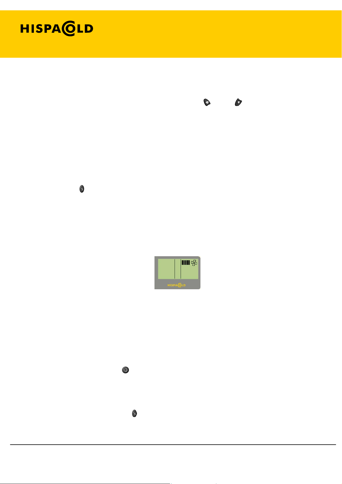
Speeds between 0 and 5 may be selected, with the following limitations:
• If the motor is stopped, no speed may be set.
• If only the driver air conditioning is running and the compressor is activated,
speed 2 will automatically be activated in the passenger compartment.
• If key (10) is pressed, speed 2 will connect.
• If the compressor is connected, the speed may not be less than 3.
When the evaporator fan setting is changed manually, the Manual Screen is displayed.
Manual Screen (evaporator fans)
1. 10. Passenger recirculation baffle adjustment.
If the passenger air conditioning is on, the position of recirculation baffles may be
varied using the passenger
(11) key.
The baffles will alternate between the exterior air (Fresh) and interior air (Recirculation)
positions, with the following limitations:
• If you have pressed the (10) key, the recirculation baffles turn to exterior air.
Page 8 of 19
MH-020-00-Ecomaster comfort user's manual Edited 06/04
Page 9
Ecomaster Comfort
• If the vehicle does not have ceiling heating installed, the baffles will set to
interior air (recirculation) position if the temperature drops two degrees lower
than that desired.
• If the interior temperature does not exceed at desired minus 2ºC for more than
4 minutes, the baffles will automatically turn to recirculation.
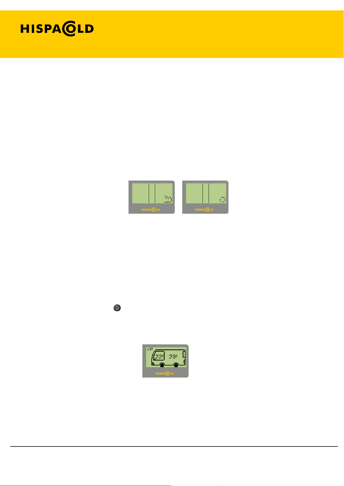
When the recirculation baffle position is changed manually, the Manual Screen is
displayed.
Manual Screen (passenger recirculation baffles)
1. 11. Passenger automatic air conditioning setting.
When the passenger recirculation baffles have been changed manually, the speed
setting of the evaporator fans, the preheater, demister or ECO mode are activated
manually, the passenger node goes into manual mode for those functions.
Pressing the passenger
(16) key returns all the controls to automatic and if the driver
node is also on automatic, the Automatic Screen is displayed, which indicates the
exterior temperature and the set of each node.
Automatic operation screen.
Page 9 of 19
MH-020-00-Ecomaster comfort user's manual Edited 06/04
Page 10
Ecomaster Comfort
1. 12. ECO Option.
The ECO option allows the driver to deactivate the air conditioning equipment compressor in
ambient conditions when its use is not necessary. While it is activated, connection of the
compressor will not be possible under any circumstance.
The
When the
(12) key is pressed to activate the ECO option.
(12) key is pressed again, or the driver or passenger (3-16) key is pressed, the
option is deactivated.
If the ECO option is activated when demisting starts, it is deactivated.
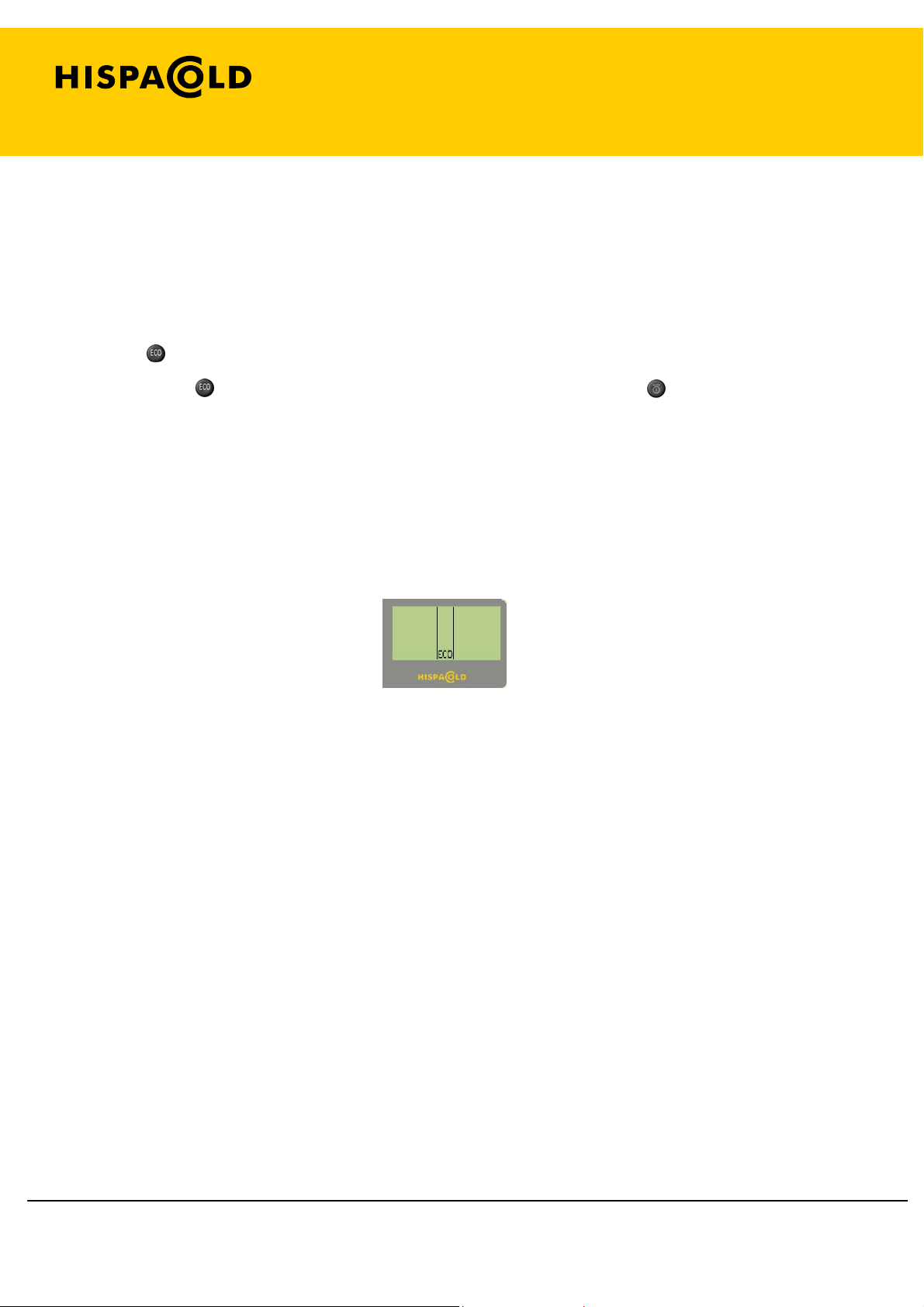
When the ECO option is selected, the Manual Screen is displayed.
ECO Manual Screen
Page 10 of 19
MH-020-00-Ecomaster comfort user's manual Edited 06/04
Page 11
Ecomaster Comfort
1. 13. Timer programming.
The
programming screen.
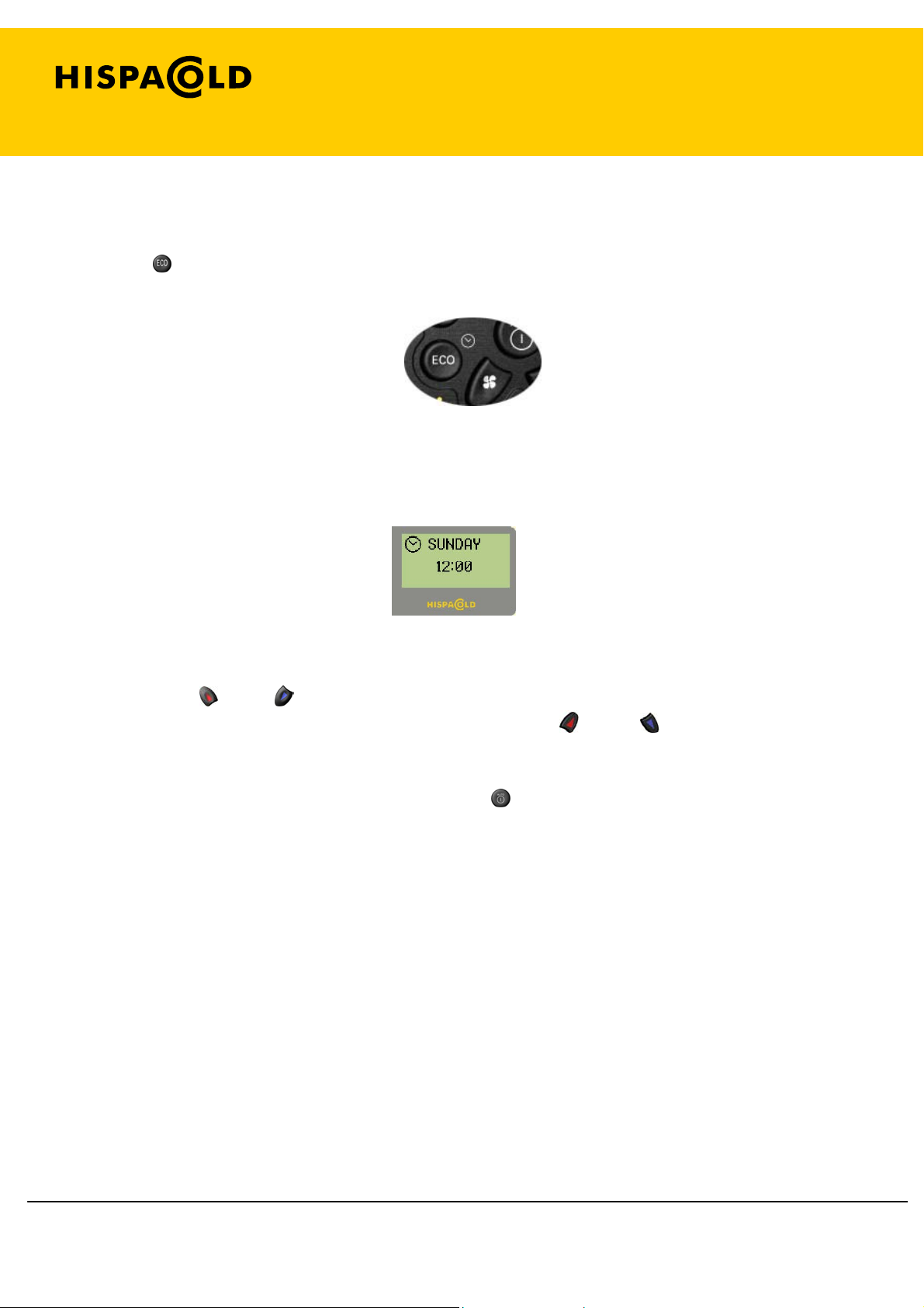
This displays the screen shown below, were the day of the week, the time and minutes
may be input.
(12) key may be pressed for 2 seconds at any time to go to the timer
Timer programming screen.
The driver
(1) and (2) keys may be used to select the day, time or minutes that appear on
the screen with a dark background, while the passenger
of the field selected.
To validate the time programmed, press the
key, or let a few seconds elapse without
pressing any key.
(15) and (17) keys change the value
Page 11 of 19
MH-020-00-Ecomaster comfort user's manual Edited 06/04
Page 12
Ecomaster Comfort
1. 14. Preheater.
The preheater has two functioning modes, programmed or normal mode.
1. 14. 1. Programmed mode.
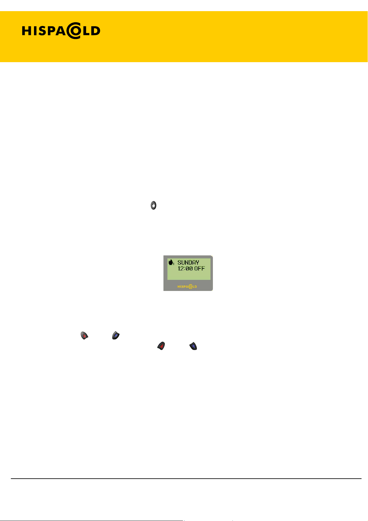
It is possible to program two activations of the preheater in day and time. Each
programming determines the day and time when we wish the bus to be warm (the
control calculates the time when the preheater must be started to achieve this).
To enter programming, press the
(8) key for 2 seconds to go to the first programming
screen. Press for a further 2 seconds to go to the second programming screen. Each
one of the screens has a flame icon, with a number that indicates whether the
programming is 1 or 2.
Preheater program screen
The driver (1) and (2) keys allow us to move around the day, time, minute and
activation fields, and the passenger
(15) and (17) keys modify their value.
The days to program may be from Monday to Sunday or 7 days (for all the days of
the week).
Single day programming will be erased once completed (reset to OFF). The ones on 7
days remain on AUTO for the next day.
To activate the programming, the field of activation must be on AUTO. To deactivate it,
just put it on OFF.
Page 12 of 19
MH-020-00-Ecomaster comfort user's manual Edited 06/04
Page 13
Ecomaster Comfort
The preheater programming always works when not in diagnostic mode.
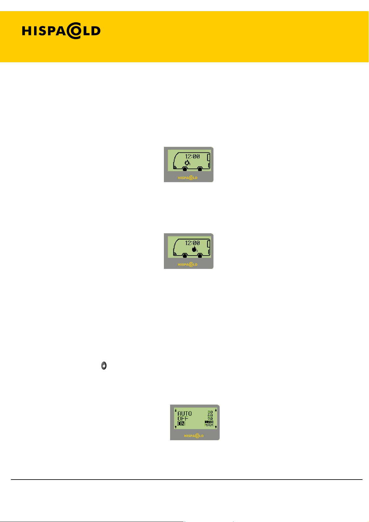
When the battery trip-switch is removed, a screen is displayed that shows whether the
preheater is programmed. If it is, a hollow flame icon will appear with a 1
(programming 1) and/or a hollow flame icon with a 2 (programming 2).
Preheater Screen programmed.
If any of the programs is running, the flame of the relevant icon is filled in.
Preheater Screen running in programmed mode.
1. 14. 2. Normal mode.
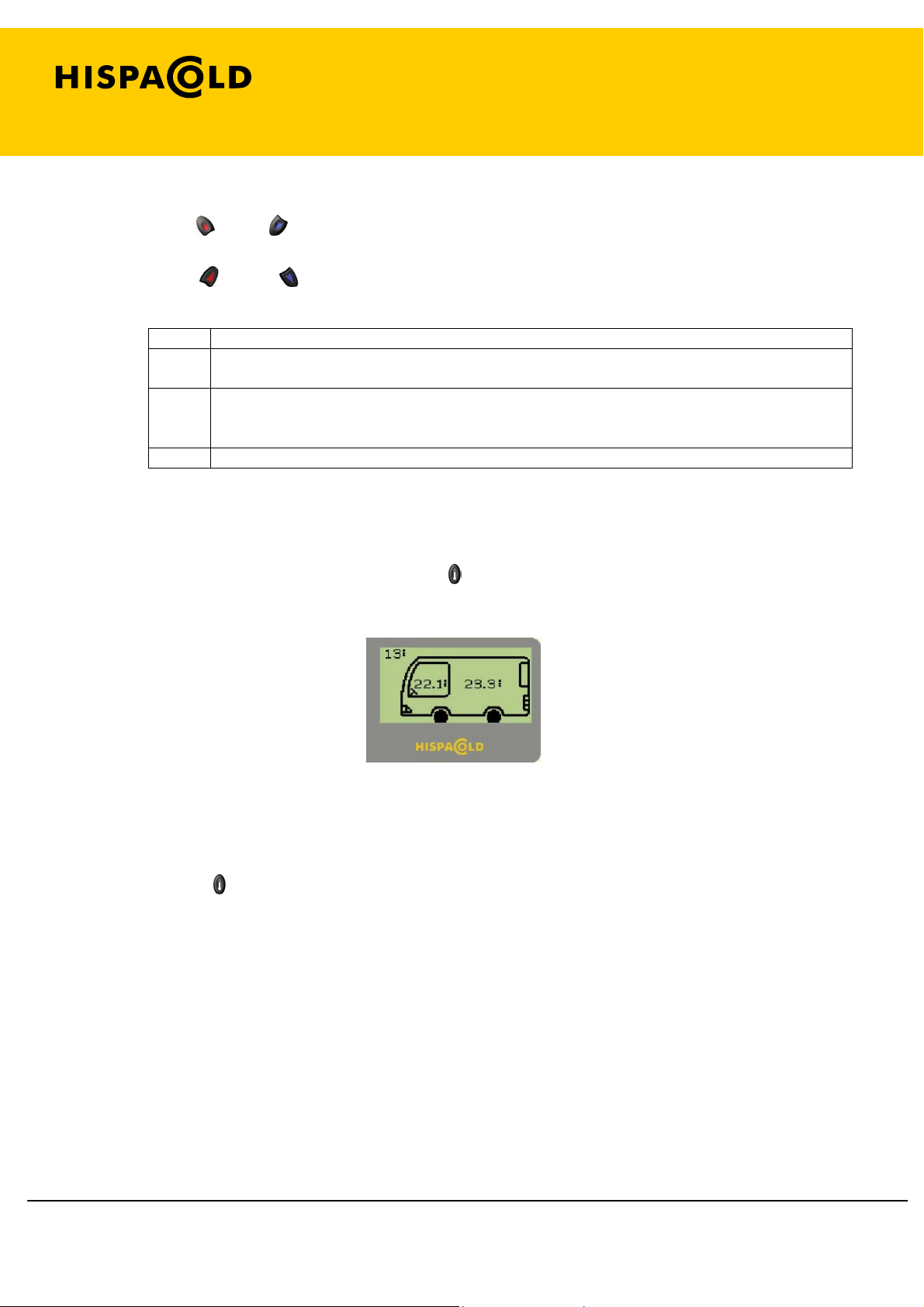
In normal mode, the preheater either operates automatically, to aid heating, or
manually for a set time that is determined by the user.
Briefly press the
(8) key to enter the preheater screen. On that screen, the flame
symbol shows whether it is running (flame filled in), either in normal or programmed
mode, or if it is deactivated (hollow flame). If it is activated in normal mode, a counter
will appear showing the time left to run.
Preheater activation screen.
Page 13 of 19
MH-020-00-Ecomaster comfort user's manual Edited 06/04
Page 14
Ecomaster Comfort
The driver
(1) and (2) keys are used to select the preheater operating mode (AUTO,
ON or OFF). Within the option ON, an activation time may be chosen using the
passenger
Mode Description
AUTO The preheater is activated if it is necessary to heat and t he external temperature is l ess than 15º or
ON The preheater connects for the time selected (except if in diagnosis mode) and then return to AUTO.
OFF The preheater is disconnected whether in AUTO or ON.
(15) and (17) keys.
the exterior probe is broken.
If MAX time is selected, the preheater remains in op eration for up to 2 hours after the vehicle motor
has stopped.
1. 15. Viewing interior temperature.
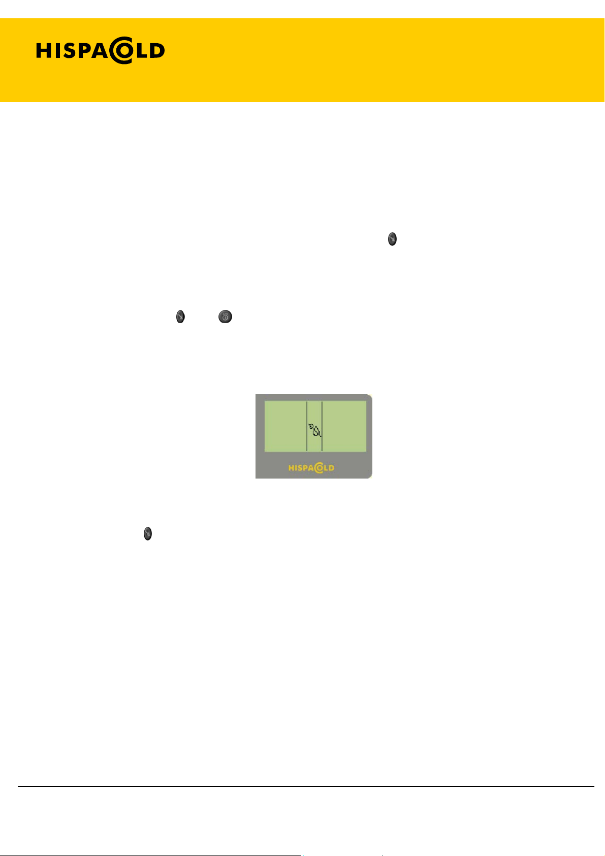
With the battery trip-switch on, press the
(9) key to be able to view the real interior
temperatures in the driver and passenger areas.
Interior temperature screen
When a few seconds have lapsed, the control will return to the screen it was on before
pressing the
(9) key.
Page 14 of 19
MH-020-00-Ecomaster comfort user's manual Edited 06/04
Page 15
Ecomaster Comfort
1. 16. Dehumidifier option.
To demist the panes, in the driver as well as the passenger area, use the dehumidifier
option.
When the control is in air conditioning mode, press the
(10) key to activate the
dehumidifier option.
The dehumidifier lasts 15 minutes and may be deactivated at will by pressing the
driver or passenger
(10) or (3-16) key again.
The Manual Screen is displayed when the dehumidifier option is activated.
Dehumidifier Manual Screen
NOTE: If the
(10) key is pressed while the ECO option is activated, it will disconnect,
as in order to dehumidify, the compressor must connect.
Page 15 of 19
MH-020-00-Ecomaster comfort user's manual Edited 06/04
Page 16
Ecomaster Comfort
1. 17. Operation in Sleeping mode
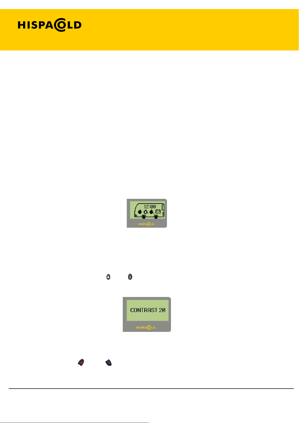
If the control is in Sleeping mode (battery trip-switch off) a screen is displayed with the
following elements:
• The system time.
• If the preheater is activated, the preheater flame connected.
• If there is a preheater program, the preheater flame with the program number
(1 or 2).
• Whether the battery level is low.
Fig 4.4 Sleeping Screen
1. 18. Screen contrast adjustment.
Simultaneously press keys
(8) and (9) for 2 seconds to go to the contrast adjustment
screen:
Contrast adjustment screen
The passenger
(15) and (17) keys are used to increase or decrease the contrast
value between 15 and 62.
Page 16 of 19
MH-020-00-Ecomaster comfort user's manual Edited 06/04
Page 17
Ecomaster Comfort
2. Error detection and indication.
When the system receives the signal from the battery trip-switch (+30), its outputs are
checked to monitor the charges there are and ensure there are none short-circuited. It
also checks the state of the probes.
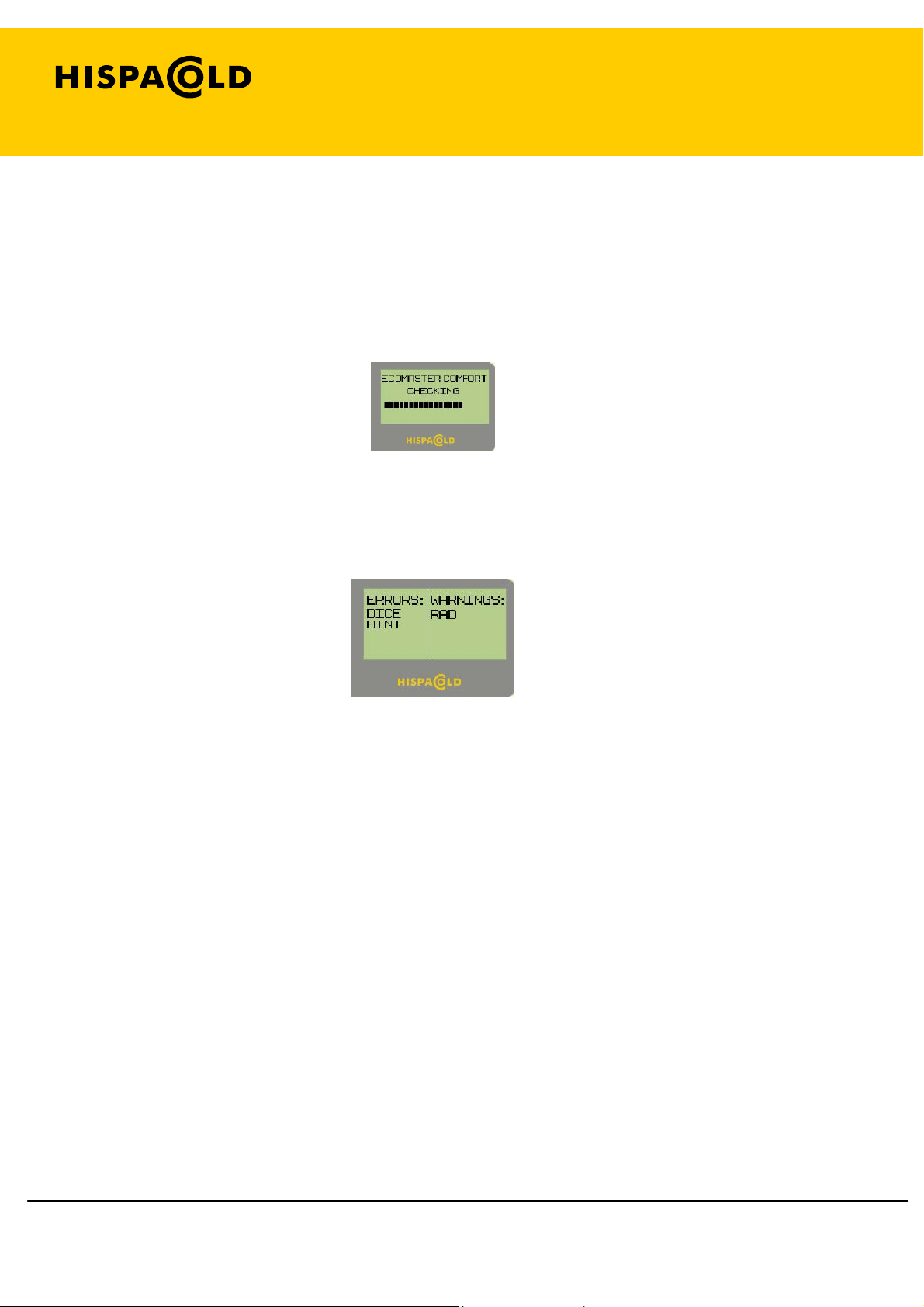
While the checking lasts, the screen will look as follows:
Initial checking screen
If any anomaly is detected, an error and warning screen will be displayed, as follows:
Error and warning screen.
Page 17 of 19
MH-020-00-Ecomaster comfort user's manual Edited 06/04
Page 18

Ecomaster Comfort
The attached tables show the relevant codes for each of the detectable problems:
Error codes.
Page 18 of 19
MH-020-00-Ecomaster comfort user's manual Edited 06/04
No. Message Description
1 DINT Short or open in the driver interior probe
2 DICE Short or open in the driver ice probe
3 DCHN Short or open in the driver channel probe
4 EXT Short or open in the driver exterior probe
5 DHB Short in the outlet of heater air (driver)
6 DV1 Short in the outlet of demister ON/OFF speed 1 (driver)
7 PMP Short in the outlet of main pump (driver)
8 PRE Short in the outlet of preheater (driver)
9 DS1 Short in the outlet of additional heater on speed setting 1 (driver)
10 DS2 Short in the outlet of additional heater on speed setting 2 (driver)
11 DV2 Short in the outlet of demister ON/OFF speed 2 (driver)
12 DV3 Short in the outlet of demister ON/OFF speed 3 (driver)
13 DFV Short in the outlet of demister valve (driver)
14 DHV Short in the outlet of heater valve (driver)
15 FWF Short in the outlet of foot/windscreen baffle (driver)
16 DRF Short in the outlet of driver recirculation baffles
17 DFB Short in the outlet of demister fans (driver)
18 FXX Preheater error number XX
19 D+30 Signal missing in +30 driver
20 PINT Short or open in the passenger interior probe
21 PCHN Short or open in the passenger channel probe
22 PICE Short or open in the passenger ice probe
23 WTR Short or open in the water probe (passengers)
24 CMP Short in the outlet of compressor (passengers)
25 FP Short in the outlet of recirculation pump (passengers)
26 PV2 Short in the outlet of evaporator ON/OFF speed 2 (passengers)
27 PV1 Short in the outlet of evaporator ON/OFF speed 2 (passengers)
28 PS1 Short in the outlet of additional strap heater speed 1 (passengers)
29 PS2 Short in the outlet of additional strap heater speed 2 (passengers)
30 C1 Short in the outlet of condenser ON/OFF (passengers)
31 PV3 Short in the outlet of evaporator ON/OFF speed 3 (passengers)
32 PRV Short in the outlet of ceiling valve (passengers)
33 PHV Short in the outlet of floor valve (passengers)
34 PRC Short in the outlet of passenger recirculation baffles passengers
35 RB Short in the outlet of right evaporator fans (passengers)
36 LB Short in the outlet of left evaporator fans (passengers)
37 CB Short in the outlet of condenser fans (passengers)
38 PRVN Has switched from detecting to not detecting ceiling valve (passengers)
39 PHVN Has switched from detecting to not detecting floor valve (passengers)
40 FPN Has switched from detecting to not detecting the recirculation pump
Page 19

Warning Codes:
Ecomaster Comfort
No. Message Description
1 POT? Inconsistency of the POT selected with the configuration detected
2 RAD Short or open in the radiation probe (driver)
3 DFBN No charge in the demister fans PWM (passengers)
4 RH Short or open in the humidity probe (passengers)
5 PRBN No charge in the right evaporator fans PWM (passengers)
6 PLBN No charge in the left evaporator fans PWM (passengers)
7 CBN No charge in the condenser fans PWM (passengers)
Page 19 of 19
MH-020-00-Ecomaster comfort user's manual Edited 06/04
 Loading...