

Page 1

Product:
LCD Television
Service Manual
Chassis: MSD6308
N10 series:
K160 series: LHD32K160NAMN
K20 series: LTDN48K20DAM
LHD24N10NAM、LHD32N10NAM
Ver 1.0
Hisense Electric Co.,Ltd.
December 20, 2013
Page 2

Contents
Contents ..................................................................................................................................................................................... - 2 -
Service Manual ......................................................................................................................................................................... - 3 -
1. Precautions and notices ................................................................................................................................................... - 3 -
1.1 Warning ................................................................................................................................................................. - 4 -
1.2 Notes ..................................................................................................................................................................... - 7 -
2. Product Specifications .................................................................................................................................................. - 10 -
2.1 Main board layout ............................................................................................................................................... - 10 -
2.2 MSD6308 includes product ................................................................................................................................ - 13 -
3. Factory/Service OSD Menu and Adjustment ................................................................................................................ - 13 -
3.1 How to enter the Factory OSD Menu .............................................................................................................. - 13 -
3.2 Factory OSD Menu ............................................................................................................................................. - 14 -
4. Software updating ......................................................................................................................................................... - 17 -
4.1 Write boot software to nand flash ....................................................................................................................... - 17 -
.4.2 Upgrading main software with Tftpd32、securecrt .......................................................................................... - 20 -
4.3 Upgrading with the USB disk ............................................................................................................................. - 23 -
5.Troubleshooting ............................................................................................................................................................. - 25 -
6. Circuit instruction ......................................................................................................................................................... - 31 -
6.1 Power assign and block diagram ........................................................................................................................ - 31 -
6.2 Main board signal process .................................................................................................................................. - 31 -
7. Schematic circuit diagram ............................................................................................................................................ - 33 -
8. Explode View ................................................................................................................................................................ - 33 -
- 2 -
Page 3

Confident
Service Manual
1. Precautions and notices
BEFORE SERVICING THE LCD TV, READ THE SAFETY PRECAUTIONS IN THIS
MANUAL.
WHEN REPLACEMENT PARTS ARE REQUIRED, BE SURE TO USE REPLACEMENT
PARTS SPECIFIED BY THE MANUFACTURER.
Proper service and repair is important to the safe, reliable operation of all Hisense Electric Co.,
Ltd Equipment. The service procedures recommended by Hisense and described in this Service
Guide are effective methods of performing service operations. Some of service
operations require the use of tools specially designed for the purpose. The special tools
should be used when and as recommended.
It is important to note that this manual contains various CAUTIONS and NOTICES which
should be carefully read in order to minimize the risk of personal injury to service personnel.
The possibility exists that improper service methods may damage the equipment. It is also
important to understand that these CAUTIONS and NOTICES ARE NOT EXHAUSTIVE.
Hisense could not possibly know, evaluate and advise the service trade of all conceivable ways
in which service might be done or of the possible hazardous consequences of each way.
Consequently, Hisense has not undertaken any such broad evaluation. Accordingly, a
serviceman that uses a service procedure or tools, which are not recommended by Hisense,
- 3 -
Page 4

Confident
must first satisfy himself thoroughly that neither his safety nor the safe of the equipment
will be jeopardized by the service method selected.
Hereafter throughout this manual, Hisense Electric Co., Ltd will be referred to as Hisense.
1.1 Warning
1.1.1
Critical components having special safety characteristics are identified with a
by the Ref.
No. in the parts list. Use of substitute replacement parts, which do not have the same specified
safety characteristics, may create shock, fire, or other hazards.
Under no circumstances should the original design be modified or altered without written
permission from Hisense. Hisense assumes no liability, express or implied, arising out of any
unauthorized modification of design. Serviceman assumes all liability.
DANGER CAUTION
TO ENSURE THE CONTINUED RELIABILITY OF THIS PRODUCT, USE ONLY
ORIGINAL MANUFACTURER'S REPLACEMENT PARTS, WHICH ARE LISTED WITH
THEIR PART NUMBERS IN THE PARTS LIST SECTION OF THIS SERVICE GUIDE.
1.1.2.
All ICs and many other semiconductors are susceptible to electrostatic discharges (ESD).
Careless handling during repair can reduce life drastically. When repairing, make sure that you
are connected with the same potential as the mass of the set by a wristband with resistance.
Keep components and tools also at this same potential.
- 4 -
Page 5

Confident
1. Never replace modules or other components while the unit is switched on.
2. When making settings, use plastic rather than metal tools. This will prevent any short
circuits and the danger of a circuit becoming unstable.
1.1.3
To prevent electrical shock, do not use this polarized ac plug with an extension cord, receptacle,
or the outlet unless the blades can be fully inserted to prevent blade exposure.
To prevent electrical shock, match wide blade or plug to wide slot, fully insert.
1.1.4
When replacement parts are required, be sure to use replacement parts specified by the
manufacturer or have the same characteristics as the original part. Unauthorized substitutions
may result in fire, electric shock, or other hazards.
1.1.5
Safety regulations require that after a repair the set must be returned in its original condition. In
particular attention should be paid to the following points.
-Note: The wire trees should be routed correctly and fixed with the mounted cable clamps.
-The insulation of the mains lead should be checked for external damage.
1.1.6
(1) Do not touch Signal and Power Connector while this product operates. Do not touch EMI
ground part and Heat Sink of Film Filter.
(2) Do not supply a voltage higher than that specified to this product. This may damage the
product and may cause a fire.
- 5 -
Page 6

Confident
(3) Do not use this product in locations where the humidity is extremely high, where it may
be splashed with water, or where flammable materials surround it. Do not install or use the
product in a location that does no satisfy the specified environmental conditions. This may
damage the product and may cause a fire.
(4) If a foreign substance (such as water, metal, or liquid) gets inside the panel module,
immediately turn off the power. Continuing to use the product may cause fire or electric
shock.
(5) If the product emits smoke, and abnormal smell, or makes an abnormal sound,
immediately turn off the power. Continuing to use the product, it may cause fire or electric
shock.
(6) Do not disconnect or connect the connector while power to the product is on. It takes
some time for the voltage to drop to a sufficiently low level after the power has been turned
off. Confirm that the voltage has dropped to a safe level before disconnecting or connecting
the connector.
(7) Do not pull out or insert the power cable from/to an outlet with wet hands. It may cause
electric shock.
(8) Do not damage or modify the power cable. It may cause fire or electric shock.
(9) If the power cable is damaged, or if the connector is loose, do not use the product:
otherwise, this can lead to fire or electric shock.
(10) If the power connector or the connector of the power cable becomes dirty or dusty, wipe
it with a dry cloth. Otherwise, this can lead to fire.
- 6 -
Page 7

Confident
(11) Use only with the cart, stand, tripod, bracket, or table specified by the manufacturer, or
sold with the apparatus. When a cart is used, use caution when moving the cart/apparatus
combination to avoid injury from tip-over.
1.2 Notes
Notes on Safe Handling of the LCD panel and during service
The work procedures shown with the Note indication are important for ensuring the safety of
the product and the servicing work. Be sure to follow these instructions.
• Before starting the work, secure a sufficient working space.
• At all times other than when adjusting and checking the product, be sure to turn OFF the
POWER Button and disconnect the power cable from the power source of the TV during
servicing.
• To prevent electric shock and breakage of PC board, start the servicing work at least 30
seconds after the main power has been turned off. Especially when installing and removing the
power board, start servicing at least 2 minutes after the main power has been turned off.
• While the main power is on, do not touch any parts or circuits other than the ones specified. If
any connection other than the one specified is made between the measuring equipment and the
high voltage power supply block, it can result in electric shock or activation of the
leakage-detection circuit breaker.
• When installing the LCD module in, and removing it from the packing carton, be sure to have
at least two persons perform the work.
- 7 -
Page 8

d
Confident
• When the surface of the panel comes into contact with the cushioning materials, be sure to
confirm that there is no foreign matter on top of the cushioning materials before the surface of
the panel comes into contact with the cushioning materials. Failure to observe this precaution
may result in, the surface of the panel being scratched by foreign matter.
• When handling the circuit board, be sure to remove static electricity from your body before
handling the circuit board.
• Be sure to handle the circuit board by holding the large parts as the heat sink or transformer.
Failure to observe this precaution may result in the occurrence of an abnormality in the soldere
areas.
• Do not stack the circuit boards. Failure to observe this precaution may result in problems
resulting from scratches on the parts, the deformation of parts, and short-circuits due to residual
electric charge.
• Routing of the wires and fixing them in position must be done in accordance with the original
routing and fixing configuration when servicing is completed. All the wires are routed far away
from the areas that become hot (such as the heat sink). These wires are fixed in position with
the wire clamps so that the wires do not move, thereby ensuring that they are not damaged and
their materials do not deteriorate over long periods of time. Therefore, route the cables and fix
the cables to the original position and states using the wire clamps.
• Perform a safety check when servicing is completed. Verify that the peripherals of the
serviced points have not undergone any deterioration during servicing. Also verify that the
screws, parts and cables removed for servicing purposes have all been returned to their proper
- 8 -
Page 9

Confident
locations in accordance with the original setup.
The lightning flash with arrowhead symbol, within an equilateral triangle is
intended to alert the user to the presence of uninsulated dangerous voltage within
the products enclosure that may be of sufficient magnitude to constitute a risk of electric shock.
The exclamation point within an equilateral triangle is intended to alert the
user to the presence of important operating and maintenance (servicing)
instructions in the literature accompanying the set.
- 9 -
Page 10
Confident
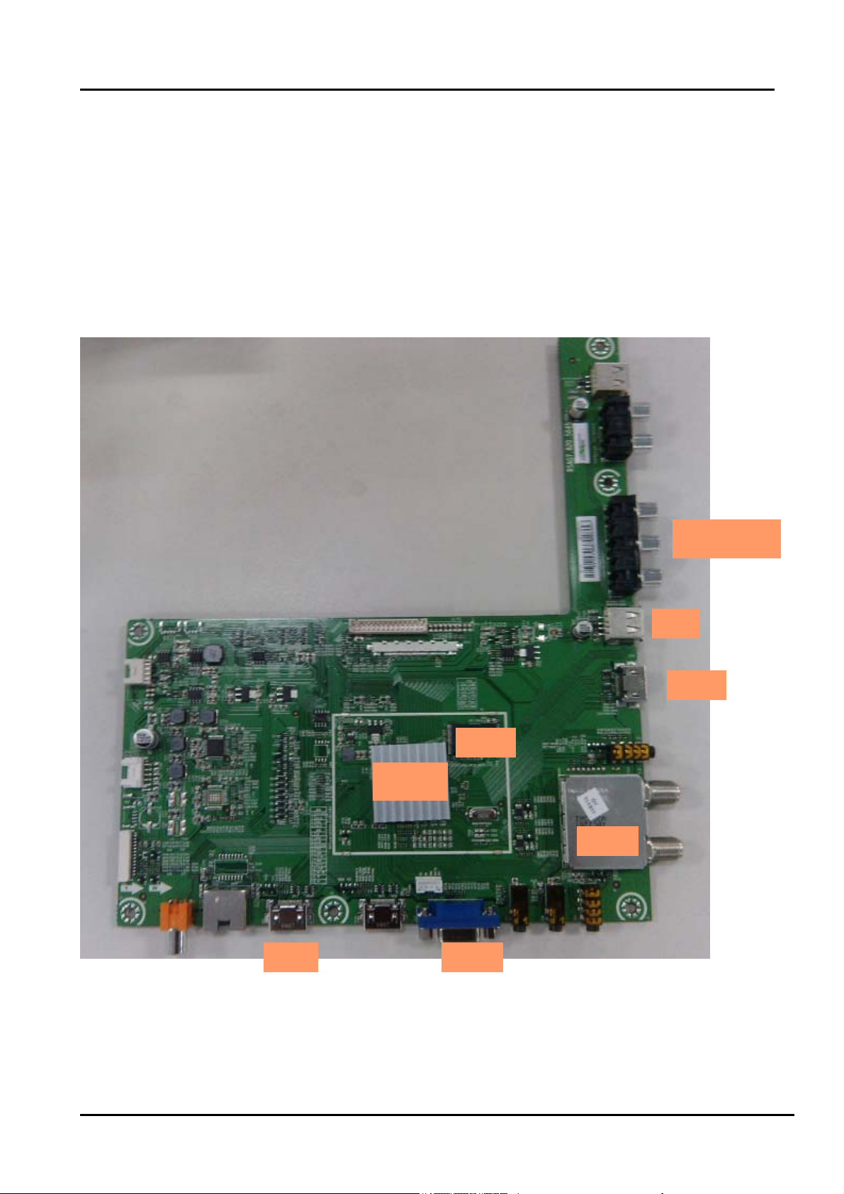
2. Product Specifications
2.1 Main board layout
2.1.1 1Main board: 5645
Take LHD32K160NAMN 、LTDN48K20DAM main board(5645)for example:
Top:
MSD6308
HDT V INPUT
USB
HDMI
Flash
Tuner
HDMI VGA
- 10 -
Page 11
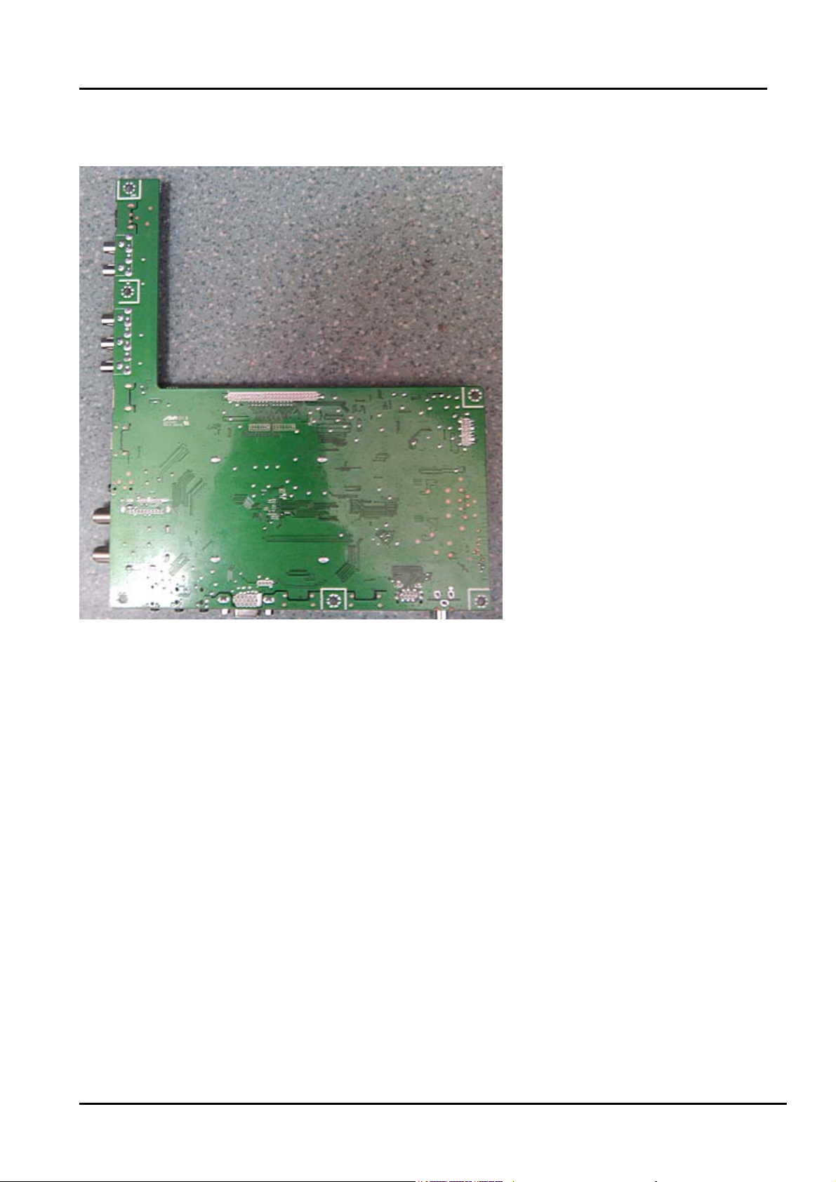
Bottom:
Confident
- 11 -
Page 12
Confident
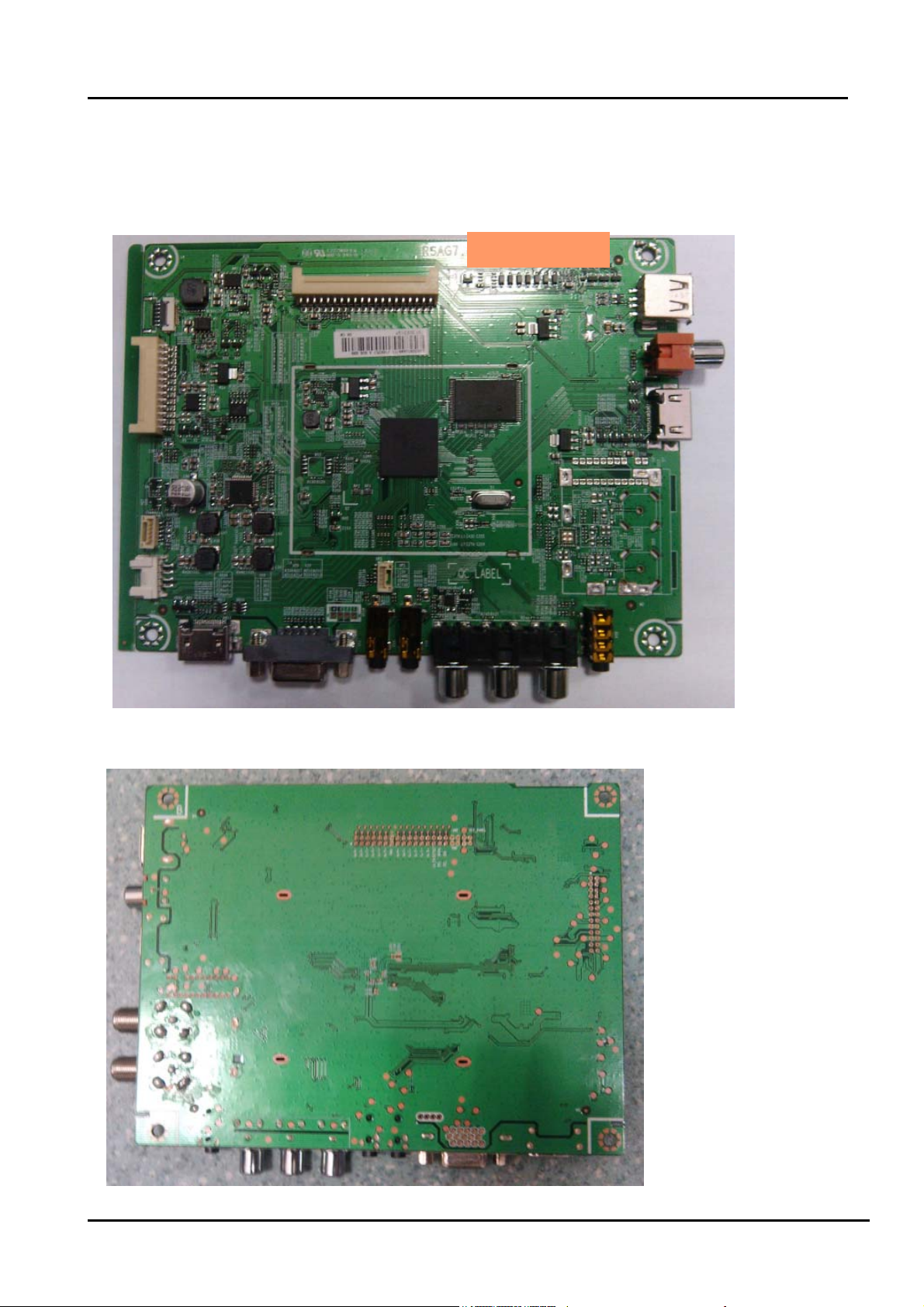
2.1.2 Main board: 5650
Take LHD24N10NAM、LHD32N10NAM 、main board(5650)for example:
Top:
RSAG7.820.5650
Bottom:
- 12 -
Page 13

Confident
2.2 MSD6308 includes product
Model Panel Mode LVDS(Main-Panel)
LHD24N10NAM V236BJ1-LE2
LHD32N10NAM HE315GH-E77
LHD32K160NAMN
LTDN48K20DAM
HE315GH-E77\ROH HX2-2X15KLB400P-CMO-3\ROH RSAG7.820.5645 RSAG7.820.5023
HD480DF-B37
1、HX2-2×20KLB400-BOE\ROH 2、
FFC-12-850\ROH
HX2-2×20KLB400-BOE\ROH RSAG7.820.5650 RSAG7.820.5268
HX2-2x22KLB500P-HS-6\ROH
Main board Power board
RSAG7.820.5650 RSAG7.820.5258
RSAG7.820.5645 RSAG7.820.5482
3. Factory/Service OSD Menu and Adjustment
3.1 How to enter the Factory OSD Menu
With user’s RC
Power on the TV.
1. Press “Menu” button and call up User OSD Menu.
2. Select “ Sound” -> “Balance” item.
3. Press number key 1->9->6 ->9 in sequence when “Balance” item is focused.
Note: If necessary, re-do number keys.
4. Factory OSD appears.
Note: Press “exit” key on the RC, which can exit factory OSD menu.
- 13 -
Page 14
Confident
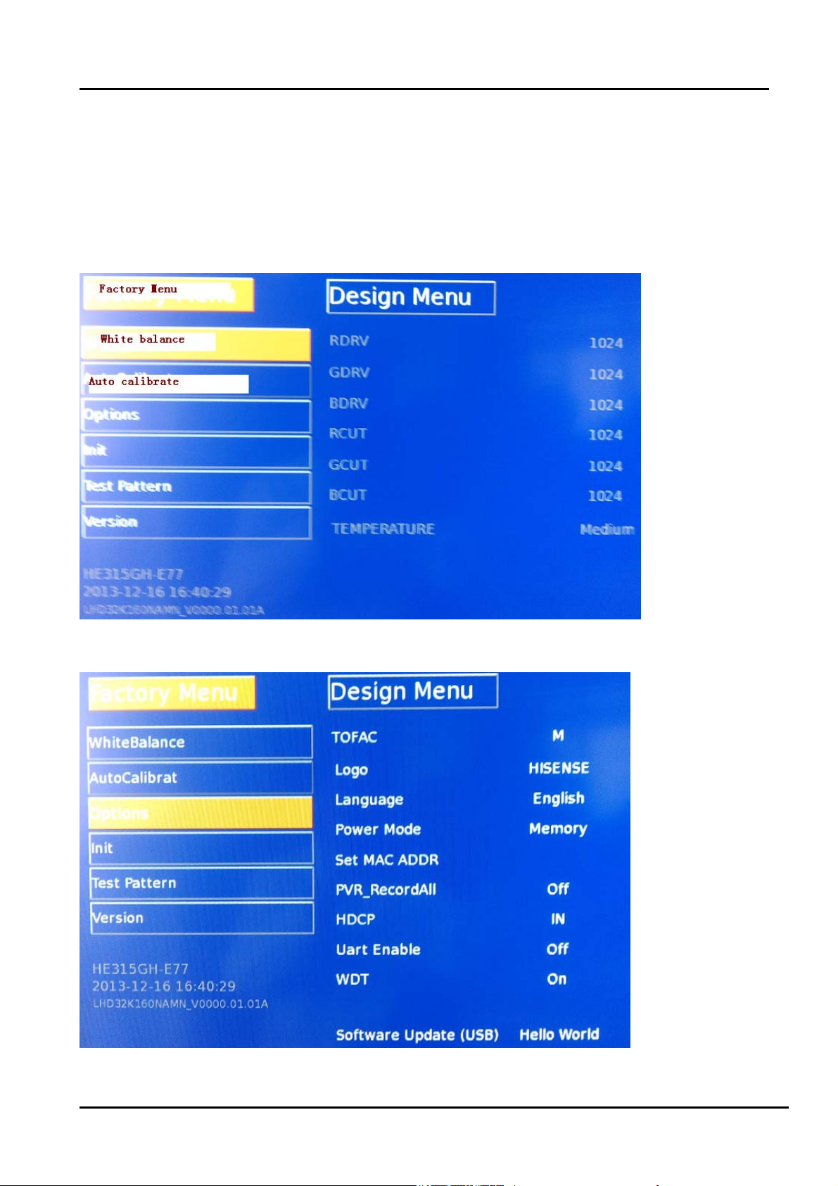
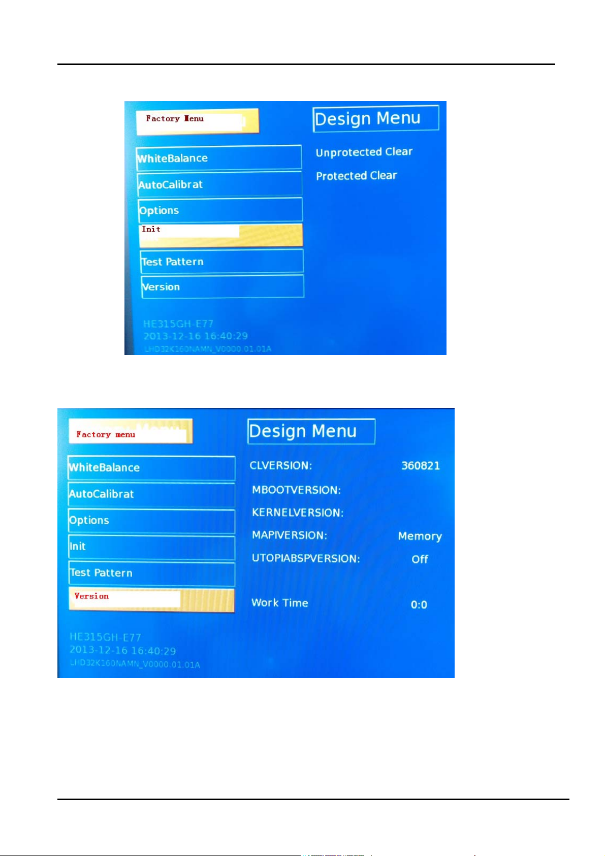
3.2 Factory OSD Menu
The Factory OSD Menu comprises Factory Menu and Design menu.
3.2.1、Factory Menu
White balance:
Option:
- 14 -
Page 15
Confident
Init:
Version:
- 15 -
Page 16

Confident
3.2.2、Design Menu
Note:
The above “Factory/Service OSD Menus” are reference only, please refer to the actual unit to
determine the appearances.
- 16 -
Page 17

Confident
4. Software updating
Software updating includes boot write and main softwar e update. Usually first write boot to nand flash
With Mstar Tool(MSTV_Tool.exe), then update main software With ISP_Tools、
Tftp and SecureCRT upgrading Tools.
4.1 Write boot software to nand flash
4.1.1 Hardware connecting
You can update the software through a special tool (as following)
Connect the Debug board to the TV use the RS232 (4 pin), the other USB port to the PC.
4.1.2 Mstar Tool (MSTV_Tool.exe) to write boot
1、Power on the TV ->connect the USB-series port Tool.-> double click the MSTV_Tool.exe
Icon(path:supernova\target\isdb.nugget\boot\CreatRomBoot_050B_256x1\tool ), and then a dialog
window will show as below.
2、Click the ” view “button. And then a dialog window will show as below.
Draw on the front of “Hex”
- 17 -
Page 18

Confident
3、Choose “Eagle/Nugget NAND program”, And then a dialog window will show as below.
- 18 -
Page 19

Confident
Now, introduce how to choose the file.
ARM \MIPS File button:
Load :supernova\target\isdb.nugget\boot\CreatRomBoot_050B_256x1\050B_TOOL.bin.
NAND File button:
Load: supernova\target\isdb.nugget\boot\CreatRomBoot_050B_256x1\RomBoot.bin.
DRAM Script button:
Load : supernova\target\isdb.nugget\boot\CreatRomBoot_050B_256x1\MIU init sequence\
DDR3_16_8X_CL11_1600_050B_1T_TOOL.bin.txt.txt
Program button:
After above all have chosen, then Click the “Program” button and wait write end. If “status” shows
*success,please reset power*, it indicates successful.
- 19 -
Page 20

Confident
.4.2 Upgrading main software with Tftpd32、securecrt
a) Run Tftpd32.exe. Browse the Base Directory file “*_dtv.a7”
Settings as following, late click “OK”.
b) Run Securecrt.exe to set up a serical section.
Select FileConnectNew seccion
- 20 -
Page 21

Confident
AC power off the TV, this time the mouse must lies on the Securecrt interface.
then AC power on the TV, at the same time press “enter” key.
you will see“<<mstar>>#”on the Securecrt interface.
(the following image).
Next input : set ipaddr 192.168.5.200;set serverip 192.168.5.211;saveenv ,then press “enter”
key. late input: “mstar mscript/auto_update.txt”to update (the following image).
- 21 -
Page 22

Confident
Note1
After software update has finished, the TV OSD appears following.
Note2:
1) Serverip “192.168.5.211”is PC LAN IP address. When update the main software.
2) you must replace you PC IP address with 192.168.5.211,and net mask with 255.255.255.0 .
- 22 -
Page 23

Confident
4.3 Upgrading with the USB disk
4.3.1 TV in normal state
1. Copy the “USBUpgrade.bin” file that MBoot and main software named to the root directory
of two USB disks respectively.
2. Insert the USB disk into the USB slot of the TV SET.
3. Press “Menu” button of remote control and call up Factory OSD Menu, choose "
OPTION "->”Software Update(USB)” item.
Detail see 3.1 HowtoentertheFactoryOSDMenu
4. Press the
Press button to select “yes” in the confirm message box, then TV will automatic update.
5. Then it will update the software automatically, Please don’t power off during the updating
process.
key on RC, it will show a confirm message box, Are you sure?
- 23 -
Page 24

Confident
6. After update succeeds, TV SET will restart automatically.
7. First update the Boot software, second update the main software. In order to
convenience, prepare two USB disks to save different software respectively.
4.3.2 TV in abnormal state
If the method of 4.3.1 can not update successfully or TV can not power on normally.
You will adopt the force update method. Insert the USB disk with USBUpgrade.bin into the U
SB slot of the TV. AC power on the TV , at the moment ,press the” menu “key of TV keypad.
Longer about 5 seconds. Then the TV will automatically update. If defeat, try again.
Note:
After update, you must confirm the software version in the “Factory Menu” and you'd better
do a " UnProtected Clear" in the “Factory Menu”.
- 24 -
Page 25

Confident
5.Troubleshooting
5.1 Troubleshooting for Remote Control
Remote control does not work
Try new batteries
NO
Replace RC
Check IR receiver
YES
YES
Replace battery
Replace remote control
Change Led & IR board
NO
Change Led & IR cable
NO
Replace main board
YES
Replace Led & IR BD
YES
Replace Led & IR cable
- 25 -
Page 26

Confident
5.2 Troubleshooting for Function Key
Buttons does not work
Check switches
YES
Check solder connections and
see if any switches are stuck.
NO
Check key board
NO
Check Key BD cable
YES
Replace Key BD
YES
Change Key BD
OK
NO
Replace main board
- 26 -
Page 27

Confident
5.3 TV won’t Power On
TV won’t power on
Is LED
light?
NO
Check Power
Output
YES
Make Sure Power
source is live
YES
NO
BLUE
RED
Panel Bright
NO
YES
Check signal
Source
YES
NO
Check Power
Cord
NO
Try Power on by
RC and Button
Neither
works
Replace Main
BD
YES
Only
one works
Both
Work
Replace
Power Cord
Check/replace IR
BD or Keypad
PCA
NO
(to contact Hisense tech support.)
Replace Main BD
Replace Panel
OK
YES
Power on
NO
Replace Power BD
YES
OK
- 27 -
Page 28

Confident
5.4 Troubleshooting for Audio
No sound
Check connecter
YES
Reconnect
NO
Check speaker wire
NO
Check speaker set
YES
YES
Replace speaker wire
Replace speaker set
NO
Replace main board
NO
YES
OK
Power Supply Board
- 28 -
Page 29

Confident
5.5 Troubleshooting for TV/VGA/HDMI input
No picture on the screen
NO
Check Signal Source
Make sure signal
source is available
YES
Check connect
NO
YES
Check cab le
NO
Replace main board
Reconnect
Replace cable
- 29 -
Page 30

Confident
5.6 Troubleshooting for YPbPr input
No picture on the screen
Check Source work or not
YES
Check connect
NO
Check Wires (Green Blue, Red)
NO
Replace main board
NO
YES
YES
Check Source Device
Reconnect
Replace wires
- 30 -
Page 31

Confident
5.7 Troubleshooting for Video input
No picture on the screen
Check Source work or not
YES
Check connect
NO
Check Cable/ Wires
NO
Replace main board
NO
YES
YES
Check Signal Source
Reconnect
Replace Cable/Wires
6. Circuit instruction
6.1 Power assign and block diagram
6.2 Main board signal process
- 31 -
Page 32

Confident
7. Schematic circuit diagram
8. Explode View
- 33 -
Page 33

5
Confident
4
3
2
1
5V_STB/2A
0R
D D
12V
TPS54328
12V
5VAIN/3A
PWR-ON/OFF
IN
5VAIN
POWER IN
IN
+12V12V
MOS
C C
X3
X1 VGA
X1
X1
X2
X1 RJ45
HDMI1
HDMI2
HDMI3
YUV
AV1AV
USB1
USB2
MSD6308RT
输入
HDMI
MHL
VGA
输入
B B
输入
YUVI
输入
输入
USB
网络输入
12V/2A
AMS1117-3.3V +3.3V_Standby/300MA
+5V_MHL/1ASWITCH
NAND_FLASH
2GBITS
SPI FLASH
16MBITS
EEPROM
32KBITS
PANELLVDS
TAS5727
EARPHONE
+1.15V_VDDC/3A
+1.5V_DDR/250MA
+3.3VAl/200MAAMS1117-3.3V5VAIN
L_OUT
R_OUT
MP1495
1117ADJ
AMS1117-3.3V 3.3V_Tuner/250MA5VAIN
FUSE 5V_USB/1A5VAIN
MOS VCC-Panel /1.5A 0R
TAS5727
I2C
L
R
L
R
MSD6308RT
AV_OUT
输出
音视频
L/R_OUT
遥控接收、键控板
光感接收、指示板
3
2
1
AV_L/R
IF1
TUNE
输入
A A
5
IF2
IF
VGA_L/R
音频输入
4
YUV_L/R
X3 AV
Page 34

5
MB:5645
Power Input
XP21
1 2
3
4
BL-ADJUST
D D
VCC-AUDIO
5VS
BLM18PG330SN1D/NC
3D_EN_I4
3D_SYNC_DY4
L52
BLM18PG330SN1D/NC
VCC-AUDIO
L57
R42 0R
VCC-A
R730R
12VS
STANDBY
BL
5
7
9
11
13
BL-ON/OFF
6
12VS
8
10
VCC-AUDIO
12
BLM18PG330SN1D/NC
14
BLM18PG330SN1D/NC
L43
L58
R19 0R
5VAIN
DVDD3V3
4
12VS
BLM18PG330SN1D/NC
L50
+12V
L51
BLM18PG330SN1D
L53
12VS
BLM21PG220SN1D
L54
+12V
BLM21PG220SN1D/NC
12VS
C447
10u/16V
5VS
L55
BLM21PG220SN1D
BLM21PG220SN1D/NC
L56
5Vstb
C448
10u/10V
VCC-A
+12V
C449
10u/16V
VCC-A
12VSTB
5Vstb
5VAIN
3
5VAIN
R9
R14
R8
10k/NC
4.7k
R11
4.7k
R22
0R
V9
MMBT3904LT1/NC
2 3
PWR-ON/OFF
1
R12
0R/NC
R13
4.7k
VBL_CTRL2
BRI_ADJ2
PWR-ON/OFF2
10k/NC
BRI_ADJ
R10
1
VBL_CTRL
1k
3.3VA
V6
MMBT3904LT1
2 3
1
R20
4.7k/NC
R15
4.7k
V10
MMBT3904LT1
2 3
R17
1k
R18
4.7k/NC
R16
0R
R25
0R/NC
2
BL-ON/OFF
R26
0R/NC
C4
10u/16V/NC
DIM_INPANEL 4
DIM_OUTPANEL 4
BL-ADJUST
+3.3V_Standby
R1
10k
R2
0R/NC
R3 4.7k
1
5Vstb
R4
10k
V2
MMBT3904LT1
2 3
1
5Vstb
R6
10k
R5
4.7k
1
R7
V1
100R
MMBT3904LT1
2 3
STANDBY
Power for Panel
for LED<=32"
+3.3V_Standby
C C
PWR-ON/OFF2
H:ON
L:OFF
PWR-ON/OFF
R40
1k
R41
12VS
R45
12VS
100k
C11
100n/16V
R43
4.7k
R44
100k
10k
V13
1
MMBT3904LT1
2 3
C44
100n/16V
1
2
3
4
+12V
C15
10u/16V
N40
AO4459
S1
S2
S3
G
+12V
8
D1
7
D1
6
D2
5
D2
for LED<=32"
R46
C12
10k
100n/16V
R47
1k
MMBT3904LT1
5Vstb 5VAIN
N42
AO4459
1
8
S1
D1
2
7
S2
D1
3
6
S3
D2
4
5
G
D2
R48
10k
1
V28
C16
1u/16V
2 3
C64
22u/6.3V
PWR-ON/OFF
C13
1u/16V
PANEL_ON/OFF2
+12V
5VAIN
BLM18PG121SN1/NC
3.3VA
L5
BLM18PG121SN1
L40
R33 10k
10k/NC
R38
C19
10u/16V
C20
100n/16V
R78 10k
R31
0R/NC
100n/16V
1
C32
R32 1k
V8
MMBT3904LT1
2 3
R27
20k
VDD_Panel
C38
1u/25V
1
2
V19
1
R29
10k
V15
MMBT3904LT1
2 3
3
AO3401L
C33 100n/16V/NC
VCC-Panel
C34
10u/16V
C35
100n/16V
5V Power-12V/5V
12VSTB
R235
10k
C226
C230
10u/16V/NC
10u/16V
靠近
DC-DC
C211
C225
1u/25V
100n/16V
B B
Core Power 1.15V-MP1495(3A)
+12V
C244
10u/16V
C31
100n/16V
10u/16V
R35
100k
R36
33k
C39
C231
100n/16V
2
7
6
8
IN
VCC
EN/SYNC
FB
3.3V Standby Power
5Vstb +3.3V_Standby
L80
BLM18PG121SN1
A A
C48
C49
100n/16V
2.2u/10V
1.25 x _1+180/110_ = 3.3V
5
3
VIN
SPX1117M3-ADJLD1117A-ADJ
8.2n/50V
MP1495
N17
8
1
3
C212
N8
VOUT
VOUT
ADJ
1
N7
VIN
EN
VRG5
SS4GND
9
R250
100k
3
SW
1
SS
5
BST
4
GND
4
2
SW
VBST
VFB
EPAD
TPS54528
R58
10k
C37
1n/50V
6
7
100n/16V
2
5
C242
100n/16V
R34
10R
R30
110R
R28
180R
L08
4.7 uH
C216
L09
6.8uH
R224
R1
130k
R219
22R/NC
R220
27k
C215
1n/50V/NC
Vout=0.765*(1+R1/R2)=5.16V
R1:130k, R2:27K//140K.
C241
15p/50V
R49
0R
R39
82k
C50
C51
100n/16V
10u/10V
Main IC Max:300mA
靠近电感
L08和DC-DC
5VS
C224
22p/50V
R229
140k
C234
22u/6.3V
C233
22u/6.3V
22u/6.3V/NC
R2
+1.15V_VDDC
R255
22k
R249
48.7k
C243
22u/6.3V
C240
22u/6.3V
C247
100n/16V
3.3V Normal Power
5VAIN
L60
C396
100n/16V
3
C741
10u/10V
3.3VA
BLM21PG220SN1D
BLM21PG220SN1D
4
放置
C235
N35
LD1117A-3.3AZ1117H-3.3
VOUT
VIN
VOUT
ADJ
1
R68
0R
DVDD3V3
L63
4
2
R67
0R/NC
C732
22u/6.3V
3.3VA
C733
22u/6.3V
C1113
100n/16V
3
1.5V Normal Power for DDR3
N36
5VAIN
C54
100n/16V
SPX1117M3-ADJLD1117A-ADJ
3
VIN
C60
10u/10V/NC
SOT-223
4
VOUT
2
VOUT
ADJ
1
R59
1k
R60
200R
2
BLM18PG121SN1
C56
10u/10V
L07
250mA
+1.5V_DDR
Hisense Electric Co.,Ltd.
Hisense Electric Co.,Ltd.
Hisense Electric Co.,Ltd.
No.11,Jiangxi Road,Qingdao,China
No.11,Jiangxi Road,Qingdao,China
No.11,Jiangxi Road,Qingdao,China
WWW.HISENSE.COM
WWW.HISENSE.COM
WWW.HISENSE.COM
Title
Title
Title
Hisense MSD6308RT
Hisense MSD6308RT
Hisense MSD6308RT
Size Schematic Name Rev
Size Schematic Name Rev
Size Schematic Name Rev
<Doc>
Custom
<Doc>
Custom
<Doc>
Custom
Date: Sheet
Date: Sheet
Date: Sheet
1
112Saturday, October 12, 2013
112Saturday, October 12, 2013
112Saturday, October 12, 2013
of
of
of
1.0
1.0
1.0
Page 35

5
MB:5645
4
3
2
1
video
Close to MST IC
RGB Interface
VGA
VGA-HSYNC5
VGA-VSYNC5
RGB1-YPBPR_RIN+7
YPBPR
RGB1-YPBPR_GIN+7
D D
RGB1-YPBPR_BIN+7
AV Interface
HDMI & Audio
C C
Mode Selection
+3.3V_Standby
R324 4.7k
R325 4.7k/NC
R335 4.7k/NC
R336 4.7k
R359 4.7k
R368 4.7k/NC
R370 4.7k
RESET
C154
2.2u/10V
+3.3V_Standby
R372 4.7k/NC
I2C address at A0.
3
VCC
APX810-29SAG-7
B B
A A
with wide trace
R201 33R
VGA-R5
R202 68R
R203 33R
VGA-G5
R204 33R
VGA-B5
HSYNC0
VSYNC0
R207 33R
R205 68R
R206 33R
R208 33R
R298
Close to MST IC
with wide trace
R338 33R
AV17
R223 68R
Audio Line IN
AV-LIN7
AV-RIN LINE_IN_0R
AV-RIN7
HD-LIN
HD-LIN7
HD-RIN
HD-RIN7
VGA-LIN
VGA-LIN5
VGA-RIN
VGA-RIN5
Audio Line Out
AV-AUOUTL0
AV-AUOUTL07
AV-AUOUTR0
AV-AUOUTR07
R294
200k
C367
L1
100n/16V
BLM18AG102SN1
Close to MSTAR IC
with width trace
SPDIF_OUT
C365
33p/50V/NC
Close to MSTAR IC
// CHIP Config {PM_CONFIG0, SPI_DI, PM_CONFIG1, PWM_PM}
SB51_EXT spi 4'b1000 Boot from 51 EXT SPI flash
HEMCU_EXT spi 4'b1001 Boot from MIPS EXT SPI flash
PM_CONFIG0
SPI_SDI
PM_CONFIG1
PWM_PM
&HDCPEEPROM
3.3VA
C108
R596
N50
A0
A12WP
A23SCL
GND
AT24C32N-10SI-2.7
2
1
8
100n/16V
VCC
7
EEPROM_WP
6
M-SCL
5
M-SDA
SDA
Close to Mstar IC
R167
100k
4.7k
1
4
N85
RST
GND
C279 2.2u/10V
C326 2.2u/10V
C381 2.2u/10V
C354 2.2u/10V
C430 2.2u/10V
C355 2.2u/10V
C259
1n/50V
33p/50V
R168
1k
C156
1n/50V
C202 47n/16V
C375 47n/16V
C204 47n/16V
C206 47n/16V
C382 47n/16V
C292 47n/16V
C348 47n/16V
C376 47n/16V
0R
C205 47n/16V
C349 47n/16V
C219 47n/16V
靠近
R295
200k
靠近
C299
4.7u/10V
R597
4.7k
C128
mstar IC
LINE_OUTL0
LINE_OUTR0
C257
1n/50V
mstar IC
AUVRM
AUVAG
R598
4.7k
System_RST
LINE_IN_0LAV-LIN
LINE_IN_1L
LINE_IN_1R
LINE_IN_2L
LINE_IN_2R
C127
33p/50V
RIN0
GIN0N
GIN0
BIN0
RIN1
GIN1N
GIN1
BIN1
SOG1
CVBS0
VCOM0
System XTAL
XTALO
XTALI
R82 0R
NOTE:
晶体频偏需要小于
R110
1M
EARPHONE_OUTL9
EARPHONE_OUTR9
FLASH
+3.3V_Standby
C200
100n/16V/NC
C52 20p/50V
12
Z1
HC-49SM24MHZ
C53 20p/50V
30PPM
N1E
H3
RIN0
RIN0P
G2
GIN0N
GIN0M
G1
GIN0
GIN0P
G3
BIN0
BIN0P
G4
HSYNC0
HSYNC0
G5
VSYNC0
VSYNC0
K3
RIN1
RIN1P
J1
GIN1N
GIN1M
J2
GIN1
GIN1P
H2
BIN1
BIN1P
J3
SOG1
SOGIN1
L2
RIN2P
L3
GIN2M
K2
GIN2P
K1
BIN2P
H5
HSYNC2
H4
VSYNC2
LINE_IN_0L
LINE_IN_0R
LINE_IN_1L
LINE_IN_1R
LINE_IN_2L
LINE_IN_2R
EARPHONE_OUTL
EARPHONE_OUTR
LINE_OUTL0
LINE_OUTR0
MSD6308RT
AUVAG
AUVRM
I2S-OUT-BCK
I2S-OUT-MCK
I2S-OUT-WS
I2S-OUT-SD
IRIN
System_RST
XTALI
XTALO
N55
8
VDD
7
HOLD#_6
6
SPI_SCK
WP#_2
SCK
5
SPI_SDI
M25P32VMNKH25L3205DM2C-12G/NC
软件必须要做写保护
CE#_0
P3
R2
U2
T3
T2
T1
R1
R3
U5
V5
T4
T5
U3
U4
N3
P2
F12
E12
D12
F10
E11
F11
D11
B7
E8
R14
AA2
Y2
SO
VSS4SI
DEBUG
VGA
YPBPR SCART
LINE_IN_0L
LINE_IN_0R
LINE_IN_1L
LINE_IN_1R
LINE_IN_2L
LINE_IN_2R
LINE_IN_3L
LINE_IN_3R
EARPHONE_OUTL
EARPHONE_OUTR
LINE_OUT_0L
LINE_OUT_0R
LINE_OUT_2L
LINE_OUT_2R
VAG
VRM
I2S_IN_BCK
I2S_IN_WS
I2S_IN_SD
I2S_OUT_BCK
I2S_OUT_MCK
I2S_OUT_WS
I2S_OUT_SD
IRIN
RESET
TESTPIN
XTALIN
XTALOUT
R129
10k/NC
1
SPI_CSN
2
SPI_SDO
3
#F_WP
XP5
1
2
3
4
B9
MDI_RN
MDI_RN 10
RN
C9
MDI_RP
MDI_RP 10
RP
B8
MDI_TN
MDI_TN 10
TN
C8
MDI_TP
MDI_TP 10
TP
A12
USB0_DM
USB0_DM 6
DM_P0
B12
USB0_DP
USB0_DP 6
DP_P0
AA7
USB1_DM
USB1_DM 6
DM_P1
Y7
USB1_DP
USB1_DP 6
DP_P1
M1
CVBS1P
N1
CVBS0
CVBS0P
N2
VCOM0
VCOM
M2
CVBS_OUT 7
CVBS_OUT1
CVBS PHYUSB
N1C
C2
HDMI0_RX0N
A_RX0N
C1
HDMI0_RX0P
A_RX0P
D3
HDMI0_RX1N
HDMI A
A_RX1N
D1
HDMI0_RX1P
A_RX1P
D2
HDMI0_RX2N
A_RX2N
E3
HDMI0_RX2P
A_RX2P
C3
HDMI0_CLKN
A_RXCN
B1
HDMI0_CLKP
A_RXCP
B2
HDMI0_HPDIN
HOTPLUGA
F1
HDMI0_SCL
DDCDA_CK
F2
HDMI0_SDA
DDCDA_DA
E2
HDMI_ARC
PAD_ARC
F3
HDMI_CEC
CEC
W5
HDMI C HDMI D
SPDIF
SPDIF_IN/3D_FLAG
MHL_CABLE_DET
MHL_VBUS_EN
R134 100R
R135 100R
HOTPLUGC
DDCDC_CK
DDCDC_DA
HOTPLUGD
DDCDD_CK
DDCDD_DA
SPDIF_OUT
HDMI2_RX0N
C_RX0N
Y5
HDMI2_RX0P
C_RX0P
W6
HDMI2_RX1N
C_RX1N
Y6
HDMI2_RX1P
C_RX1P
AA6
HDMI2_RX2N
C_RX2N
W7
HDMI2_RX2P
C_RX2P
AA4
HDMI2_CLKN
C_RXCN
Y4
HDMI2_CLKP
C_RXCP
V4
HDMI2_HPDIN
W4
HDMI2_SCL
W3
HDMI2_SDA
C6
HDMI3_RX0N
D_RX0N
B5
HDMI3_RX0P
D_RX0P
C5
HDMI3_RX1N
D_RX1N
B4
HDMI3_RX1P
D_RX1P
A4
HDMI3_RX2N
D_RX2N
C4
HDMI3_RX2P
D_RX2P
A6
HDMI3_CLKN
D_RXCN
B6
HDMI3_CLKP
D_RXCP
A2
HDMI3_HPDIN
A3
HDMI3_SCL
B3
HDMI3_SDA
E10
D10
SPDIF_OUT
F4
MHL_CABLE-DET
F5
MHL_VBUS-EN
UART-RX
UART-TX
Analog Audio
I2S
MHL
MSD6308RT
R130
4.7k/NC
5Vstb
R221
R222
4.7k
4.7k
UART_RX
UART_TX
UART_TX5 UART_RX5
NAND & CI & TS & Front End
N1B
T19
PCM_D0
T21
PCM_D1
T20
PCM_D2
Y18
PCM_D3
AA18
PCM_D4
W19
PCM_D5
Y17
PCM_D6
AA19
PCM_D7
V19
PCM_A0
U20
PCM_A1
W20
PCM_A2
Y16
PCM_A3
P19
PCM_A4
R20
PCM_A5
T18
PCM_A6
U19
PCM_A7
Y19
PCM NAND
PCM_A8
W21
PCM_A9
W17
PCM_A10
Y20
PCM_A11
U18
PCM_A12
V21
PCM_A13
U17
PCM_A14
T17
PCM_CD_N
W18
PCM_CE_N
AA20
PCM_IORD_N
Y21
PCM_IOWR_N
V18
PCM_IRQA_N
AA16
PCM_OE_N
V20
PCM_REG_N
R21
PCM_RESET
P20
PCM_WAIT_N
R19
PCM_WE_N
T10
NAND_ALE
NAND_ALE11
NAND_CEZ11
NAND_CEZ111
NAND_CLE11
NAND_DQS11
NAND_RBZ11
NAND_REZ11
NAND_WEZ11
NAND_WPZ11
NAND_D[7:0]11
NAND_CEZ
NAND_CEZ1
NAND_CLE
NAND_DQS
NAND_RBZ
NAND_REZ
NAND_WEZ
NAND_WPZ
NAND_D0
NAND_D1
NAND_D2
NAND_D3
NAND_D4
NAND_D5
NAND_D6
NAND_D7
NAND_ALE
V8
NAND_CEZ
U8
NAND_CEZ1
U9
NAND_CLE
U11
NAND_DQS
U7
NAND_RBZ
V7
NAND_REZ
T11
NAND_WEZ
T7
NAND_WPZ
Y8
NAND_AD0
W9
NAND_AD1
AA9
NAND_AD2
W10
NAND_AD3
Y10
NAND_AD4
W11
NAND_AD5
W12
NAND_AD6
Y12
NAND_AD7
TS INVIF
TS OUT
TUNER_I2C_SCL
TUNER_I2C_SDA
TS0_SYNC
TS1_SYNC
W14
TS0_D0
U16
TS0_D1
T16
TS0_D2
Y13
TS0_D3
AA15
TS0_D4
Y15
TS0_D5
Y14
TS0_D6
V15
TS0_D7
W15
TS0_CLK
W16
TS0_VLD
V16
AA13
TS1_D0
W13
TS1_D1
U13
TS1_D2
V13
TS1_D3
T12
TS1_D4
T15
TS1_D5
U15
TS1_D6
U14
TS1_D7
T13
TS1_CLK
U12
TS1_VLD
T14
V1
VIFP
VIFP
W1
VIFM
VIFM
Y1
IFAGC
IFAGC
AA3
TUNER_SW
TGPIO0
V2
TGPIO1
Y3
TUNER_SCL
W2
TUNER_SDA
GPIO & LVDS
N1D
K17
HDMI0_RX0N 8
HDMI0_RX0P 8
HDMI0_RX1N 8
HDMI0_RX1P 8
HDMI0_RX2N 8
HDMI0_RX2P 8
HDMI0_CLKN 8
HDMI0_CLKP 8
HDMI0_HPDIN 8
HDMI0_SCL 8
HDMI0_SDA 8
HDMI_ARC 8
HDMI_CEC 8
HDMI2_RX0N 8
HDMI2_RX0P 8
HDMI2_RX1N 8
HDMI2_RX1P 8
HDMI2_RX2N 8
HDMI2_RX2P 8
HDMI2_CLKN 8
HDMI2_CLKP 8
HDMI2_HPDIN 8
HDMI2_SCL 8
HDMI2_SDA 8
HDMI3_RX0N 8
HDMI3_RX0P 8
HDMI3_RX1N 8
HDMI3_RX1P 8
HDMI3_RX2N 8
HDMI3_RX2P 8
HDMI3_CLKN 8 LAN_LED010
HDMI3_CLKP 8
HDMI3_HPDIN 8
HDMI3_SCL 8
HDMI3_SDA 8
SPDIF_OUT 7
MHL_CABLE-DET 8
MHL_VBUS-EN 8
RF
100n/16V
VIFP
C352
DIFP 12
100n/16V
VIFM
C353
DIFM 12
R355
10k
3.3VA
IFAGC
R357 0R
IF-AGC-T 12
C351
detect NAND Flash Power
when detect source is from 5V,
change resistance ,make sure
detect power 1VPP.
22n/25V
12VS
5Vstb
R376
R328
100k
0R
R339
1M
R352
1k
POWER_DET
R363
100k
Other
M-SCL
M_I2C_SCL
R377 100R
M-SCL4,9
M-SDA4,9
ARC_DET8
ARC_DET
R379 100R
M_I2C_SDAM-SDA
I2S
I2S-OUT-WS
R79
33R
I2S-OUT-MCK
R87
33R
I2S-OUT-BCK
R93
33R
I2S-OUT-SD
R105
33R
10p/50V/NC
C120
C95
C111
C112
10p/50V/NC
10p/50V/NC
10p/50V/NC
3D_EN4
MUTE_AMP9
BRI_ADJ1
I2S-OUT_WSO 9
I2S-OUT_MCKO 9
I2S-OUT_BCKO 9
I2S-OUT_SDO 9
MSD6308RT
PCM_PWR_EN3D_EN
MUTE_AMP
BRI_ADJ
PWM_PM
KEY0_IN
LED
ARC_DET
KEY1_IN
POWER_DET
SPI_SCK
SPI_SDI
SPI_SDO
SPI_CSN
HP_DEC
HP_DEC8
MUTE_DRV632
MUTE_DRV6328
UART-RX
UART-TX
M_I2C_SCL
M_I2C_SDA
LAN_LED110
K18
J18
D9
E4
E5
F7
F6
F8
A10
B10
C11
B11
C21
C20
E7
D7
B21
B20
L17
L18
M18
M16
M17
E9
F9
3D_EN/PCM_PWR_EN
AMP_MUTE
BRI_ADJ
PWM_PM
KEY0_IN
LED_R
ARC_DET
KEY1_IN
POWER_DET
PM_SPI_CK
PM_SPI_DI
PM_SPI_DO
PM_SPI-CSN
UART_RX2
UART_TX2
M_UART0_RX
M_UART0_TX
M_I2C_SCL
M_I2C_SDA
SPI1_CK
SPI1_DI
SPI2_CK
SPI2_DI
VSYNC_LIKE
LAN_LED0
LAN_LED1
PWM SAR SPI
GPIO
LOCAL DIMMING
LVDS
TCON
PM_TX/PANEL_ON/OFF
GPIO_PM
MSD6308RT
PM_RX/VBL_CTRL
FLASH_WP
E2PROM_WP
PWR_ON/OFF
PM_CONFIG0
PM_CONFIG1
3D_LR_IN
LVACKN
LVACKP
LVBCKN
LVBCKP
LVSYNC
LHSYNC
TCON0
TCON1
TCON2
TCON3
TCON4
TCON5
TCON6
TCON7
TUNER_SW 9
RST_AMP 9
TUNER_SCL 12
TUNER_SDA 12
LVA0N
LVA0P
LVA1N
LVA1P
LVA2N
LVA2P
LVA3N
LVA3P
LVA4N
LVA4P
LVB0N
LVB0P
LVB1N
LVB1P
LVB2N
LVB2P
LVB3N
LVB3P
LVB4N
LVB4P
LDE
LCK
POWER&GND
+1.15V_VDDC
AVDDL_MOD
DVDD_NODIE
AVDD_NODIE
AVDD_AU
AVDD_DMPLL
AVDD_DVI
layout
方便否
K21
LVA0N
LVA0N 4
J19
LVA0P
LVA0P 4
K19
LVA1N
LVA1N 4
K20
LVA1P
LVA1P 4
L19
LVA2N
LVA2N 4
L20
LVA2P
LVA2P 4
M21
LVACLKN
LVACLKN 4
M20
LVACLKP
LVACLKP 4
N21
LVA3N
LVA3N 4
M19
LVA3P
LVA3P 4
N19
LVA4N
LVA4N 4
N20
LVA4P
LVA4P 4
E19
LVB0N
LVB0N 4
E20
LVB0P
LVB0P 4
F21
LVB1N
LVB1N 4
F20
LVB1P
LVB1P 4
G21
LVB2N
LVB2N 4
F19
LVB2P
LVB2P 4
G19
LVBCLKN
LVBCLKN 4
G20
LVBCLKP
LVBCLKP 4
H19
LVB3N
LVB3N 4
H20
LVB3P
LVB3P 4
J21
LVB4N
LVB4N 4
J20
LVB4P
LVB4P 4
D20
D19
D21
C19
R18
P17
N18
N17
P16
N16
R17
R16
D6
PM_TX
PANEL_ON/OFF 1
E6
PM_RX
VBL_CTRL 1
1
A7
FLASH_WP
TP204
C10
EEPROM_WP
C7
LED0
C12
PWR-ON/OFF
PWR-ON/OFF 1
A9
PM_CONFIG0
G6
PM_CONFIG1
+1.15V_VDDC
C363
100n/16V
2.2u/10V/NC
nodie
DVDD_NODIE
C350
1u/10V/NC
Close to MST IC
Standby Power 3.3V
+3.3V_Standby
C378
100n/16V/NC
10u/10V
Normal Power 3.3V
3.3VA
C369
10u/10V
KEY PAD& IR
BLM18PG121SN1/NC
VDDC
C13
VDDC
C14
VDDC
E14
VDDC
F13
VDDC
G9
VDDC
G10
VDDC
G11
VDDC
G12
VDDC
H9
VDDC
J9
VDDC
B13
DVDD_DDR
H10
DVDD_DDR
A13
DVDD_RX_0
H11
DVDD_RX_0
K9
AVDDL_MOD
H7
DVDD_NODIE
J6
AVDD_NODIE
K5
AVDD_AU33
L5
AVDD3P3_DMPLL
K4
AVDD_DVI_USB_MPLL
L4
AVDD_DVI_USB_MPLL
A15
GND
A18
GND
B15
GND
B18
GND
C15
GND
C18
GND
D15
GND
D18
GND
E15
GND
E18
GND
F15
GND
F18
GND
G7
GND
G8
GND
G15
GND
G18
GND
H6
GND
H8
GND
H18
GND
J4
GND
J8
GND
J16
GND
J17
GND
K8
GND
K15
GND
K16
GND
L6
GND
L7
GND
L8
GND
L9
GND
L10
GND
L11
GND
L12
GND
L13
GND
L14
GND
L15
GND
L16
GND
MSD6308RT
CORE POWER
C256
C263
C260
C269
100n/16V
100n/16V/NC
100n/16V/NC
100n/16V/NC
+1.5V_DDR
C249
10u/10V
AVDD_DVI
AVDD_NODIE
C278
C281
C286
100n/16V
100n/16VNC
AVDD_PLLVDDP
AVDD_MOD
C258
C270
100n/16V/NC
100n/16V
XP8
1
IR_IN
2
3
LED_CTL_IR
4
BLM18PG121SN1
5
6
7
R428 10R
8
R650 0R
9
R429 10R
10
R648
11
3D_TB
R649
12
13
3D_TB
15
14
7
5VAIN
L22
6
5
4
R2250R
3
KEY1
2
R228 0R
1
KEY0
XP9
5Vstb
R177
4.7k/NC
C189
20p/50V
C238
L21
R190
100R
0R/NC
0R
R176
2.2k
100n/16V/NC
2.2u/10V
C373
100n/16V/NC
C272
1u/10V
+3.3V_Standby
C273
C371
KEY1
R175
2.2k
100n/16V
BLM18PG121SN1
100n/16V/NC
+3.3V_Standby
KEY0
LED_CTL0
IRINIR_IN
C360
100n/16V/NC
DDR3 POWER
C253
C366
100n/16V/NC
AVDD_DMPLL
L06
C383
R643 0R/NC
R638 0R
100n/16V
C187
100n/16V
R198 1k
R192 1k
C203
C201
1n/50V
1n/50V
AVDDL_MOD
C368
100n/16V/NC
C332
100n/16V
+3.3V_Standby
BLM18PG121SN1
C280
100n/16V
C648
C183
2.2u/10V
N1F
A14
FB
VDDC
B14
AVDD_DDR_CMD0
AVDD_DDR_CMD0
AVDD_DDR_DATA0
AVDD_DDR_DATA0
AVDD_DDR_DATA0
AVDD_DDR_DATA0
AVDD_DRAM
AVDD_DRAM
AVDD_PLL
AVDD_MOD
AVDD_MOD
AVDD5V_MHL_C
AVDD5V_MHL_D
VSENSE_VDD
GND_EFUSE
MCP_VDDC
MCP_VDDC
MCP_VDD33
MCP_AVDD
MCP
MCP_TESTPIN
C255
100n/16V
L7
+3.3V_Standby
5Vstb
KEY1_IN
KEY0_IN
VDDP
VDDP
GND
GND
GND
GND
GND
GND
GND
GND
GND
GND
GND
GND
GND
GND
GND
GND
GND
GND
GND
GND
GND
GND
GND
GND
GND
GND
GND
GND
GND
GND
GND
GND
GND
GND
GND
GND
GND
GND
GND
AVDD_DRAM
100n/16V
C261
100n/16V/NC
AVDD_AU
C282
100n/16V/NC
+1.5V_DDR
B16
J10
A16
J11
J12
K12
A17
B17
M8
VDDP
N8
N9
AVDD_PLL
M10
AVDD_MOD
N10
V3
AVDD5V_MHL_C
D4
AVDD5V_MHL_D
1
TP208
1
R15
TP201
R13
R6
+1.2V_DEMOD
R7
P9
+3.3V_DEMOD
R8
R12
M4
M6
M9
M11
M12
M13
M14
M15
N4
N6
N11
N12
N13
N14
N15
P5
P10
P11
P12
P13
P14
P15
R5
R9
R10
R11
T6
T8
T9
U6
U10
V6
V10
V12
W8
Y9
Y11
AA10
AA12
C283
5Vstb
5Vstb
R212
NC/10k
R211
R210
LED_CTL_IR
10k
0R
R213
V26
1
10k/NC
MMBT3904LT1/NC
V20
1
LED
R209 10k
C196
100n/16V
LED0
R216 10k
C199
100n/16V
2 3
MMBT3904LT1
2 3
5Vstb
5Vstb
R218
10k
R217
R215
LED_CTL0
10k
0R/NC
R214
V29
1
10k
MMBT3904LT1
V27
1
2 3
MMBT3904LT1
2 3
Hisense Electric Co.,Ltd.
Hisense Electric Co.,Ltd.
Hisense Electric Co.,Ltd.
No.11,Jiangxi Road,Qingdao,China
No.11,Jiangxi Road,Qingdao,China
No.11,Jiangxi Road,Qingdao,China
WWW.HISENSE.COM
WWW.HISENSE.COM
WWW.HISENSE.COM
Title
Title
Title
Hisense MSD6308RT
Hisense MSD6308RT
Hisense MSD6308RT
Size Schematic Name Rev
Size Schematic Name Rev
Size Schematic Name Rev
<Doc>
Custom
<Doc>
Custom
<Doc>
Custom
Date: Sheet
Date: Sheet
5
4
3
2
Date: Sheet
1
1.0
1.0
1.0
of
of
of
212Tuesday, October 29, 2013
212Tuesday, October 29, 2013
212Tuesday, October 29, 2013
Page 36

5
MB:5645
4
3
2
1
MSD MIU
D D
AVDD_DRAM
N1A
R304
1k
S1
MIU0
S4
M1
M2
M3
DDR3_RESETB
DDR3_CKE
R306
1k
C C
B B
A19
A20
B19
R305
240R
S5
DDR3_RESETB
DDR3_CKE
ZQ
MSD6308RT
D4
S6
D4
S2
D4
S3
MARK
MARK
MARK
Q1
123
A A
5
D4
4
4
D4
D4
Hisense Electric Co.,Ltd.
Hisense Electric Co.,Ltd.
Hisense Electric Co.,Ltd.
No.11,Jiangxi Road,Qingdao,China
No.11,Jiangxi Road,Qingdao,China
No.11,Jiangxi Road,Qingdao,China
WWW.HISENSE.COM
WWW.HISENSE.COM
WWW.HISENSE.COM
Title
Title
Title
Hisense MSD6308RT
Hisense MSD6308RT
Hisense MSD6308RT
Size Schematic Name Rev
Size Schematic Name Rev
Size Schematic Name Rev
Date: Sheet
Date: Sheet
3
Date: Sheet
2
<Doc>
A
<Doc>
A
<Doc>
A
312Saturday, October 12, 2013
312Saturday, October 12, 2013
312Saturday, October 12, 2013
1
1.0
1.0
1.0
of
of
of
Page 37

5
MB:5645
R502
0R/NC
1脚为从TCON来的L/R帧同步2脚为L/R帧同步,去TCON
XP6
4
6
8
10
12
14
16
18
20
22
24
26
28
30
32
34
36
38
40
42 41
44 43
12
3
5
7
9
11
13
15
17
19
21
23
25
27
29
31
33
35
37
39
3D_SYNC_O_P
PWM1_PANEL
LVA4P
LVA3P
LVACLKP
LVA2P
LVA1P
LVA0P
LVB4P
LVB3P
LVBCLKP
LVB2P
LVB1P
LVB0P
LD_EN
SEL
I2C-SCL-3D
VCC-PanelVCC-Panel
3D_SYNC_I_P
PWM2_PANEL
LVA4N
LVA3N
D D
LVACLKN
LVA2N
LVA1N
LVA0N
LVB4N
LVB3N
LVBCLKN
LVB2N
LVB1N
LVB0N
BIT_SEL
3D_EN_I
I2C-SDA-3D
GPIO08
R281
GPIO07
3D_SYNC_I_P
100R_NC
PWM2_PANEL
R716
0R/NC
LVA4N
LVA3N
LVACLKN
LVA2N
LVA1N
LVA0N
LVB4N
LVB3N
LVBCLKN
LVB2N
LVB1N
LVB0N
R714
0R/NC
BIT_SEL LD_EN
R282
100R/NC
DIM_INPANEL 3D_EN_I
R280
AI
100R/NC
VCC-Panel VCC-Panel
LVDS PORT A
C C
R425
10k
3
V38
MMBT3904LT1
2
DVDD3V3
5VAIN
DVDD3V3
R348
1k/NC
R433
1k/NC
3D_SYNC_I
3D_SYNC_O
3D_SYNC_I
R342 0R
R345 0R/NC
3D_SYNC to POWER
该芯片的作用是将屏发出的SG方波信号转换成眼镜能识别的方波信号转换成38KHz红外载波方式的信号
3D_FS_VCC
L61
BLM18PG121SN1
L62
BLM18PG121SN1/NC
R367 0R/NC
N34
1
A
VCC
2
B
GND3Y
SN74AHC1G86DBVT/NC
3D_OUT
10u/10V
5
4
C316
3D_FS_VCC
100n/16V
R401
R409
R414
10k
C317
3D_FS_VCC
DVDD3V3
1k
1k
R402
10k/NC
1
R354
4.7k/NC
5VAIN
V44
3
MMBT3904LT1
2
R390
R353
R346
10k
10k
10k
C318
100n/16V
R387
100R
R413
10k
3D_TB
R422
0R/NC
R431
1k/NC
DVDD3V3
1
3D_SYNC
DVDD3V3
3D_OUT
R432
4.7k/NC
R349
4.7k/NC
3D_SYNC_I为给屏的30Hz同步信号
B B
R384
10k
from panel
R408
GPIO08 3D_SYNC_O
R360
GPIO07
0R
3D_FS_VCC
R392
10k/NC
3D_CTRL
R395
10k/NC
0R
3D_SYNC_I
R394
1k
from 5652
1
R366
R380
0R/NC
R389
10K
R420
10k
3
V35
MMBT3904LT1
2
0R
11 12
13 14
15 16
17 18
19 20
21 22
23 24
25 26
27 28
29 30
31 32
33 34
35 36
37 38
39 40
41 42
43 44
45 46
47 48
49 50
3D_SYNC_DY
N101
1
VDD
CLKIN2ICSPDAT
CLKOUT3ICSPCLK
4
VPP
PIC12F609-I
XP15
1 2
3 4
5 6
7 8
9 10
VSS
COUT
C319
15p/50V
4
+12V
3D_SYNC_O_P
PWM1_PANEL
LVA4P
LVA3P
LVACLKP
LVA2P
LVA1P
LVA0P
LVB4P
LVB3P
LVBCLKP
LVB2P
LVB1P
LVB0P
SEL
I2C-SCL-3DI2C-SDA-3D
8
7
6
5
R284
R718
R717
R715
0R/NC
100R/NC
R278
DIM_OUTPANEL
R277 100R/NC
3D_SYNC MCU
5VAIN
3D_FS_VCC
R350
R417
10k
10k
3D_TB
R388
0R
调制好的78K SG同步信号
0R/NC
0R/NC
0R/NC
R385
0R
C340
100n/16V
PWM2_PANEL
SEL
3D_SYNC_DY
DVDD3V3
PWM1_PANEL
R386
0R/NC
1
2
3
XP10
4
5
DVDD3V3
61
60
59
58
57
56
R343
4.7k/NC
R344
4.7k/NC
XP18
55
1
2
3
4
5
6
7
8
9
10
11
12
13
14
15
16
17
18
19
20
21
22
23
24
25
26
27
28
29
30
31
32
33
34
35
36
37
38
39
40
41
42
43
44
45
46
47
48
49
50
51
52
53
54
FI-RES-HF-51
BIT_SEL
LVA4P
LVA4N
LVA3P
LVA3N
LVACLKP
LVACLKN
LVA2P
LVA2N
LVA1P
LVA1N
LVA0P
LVA0N
3D_SYNC_I_P
3D_EN_I
LVB4P
LVB4N
LVB3P
LVB3N
LVBCLKP
LVBCLKN
LVB2P
LVB2N
LVB1P
LVB1N
LVB0P
LVB0N
LD_EN
PWM1_PANEL
PWM2_PANEL
3D_SYNC_O_P
R498
R497
VCC-Panel
SEL
100R
100R
0R/NC
R419
I2C-SDA-3D
I2C-SCL-3D
RESERVED
3
DVDD3V3
4.7k/NC
10K/NC
R445
R444
Power decouple
VCC-Panel
C436
C453
10u/16V
100n/16V
Note:靠近LVDS
插座
3D_EN 3D_EN_I
MEMC_ON/OFF
LD_EN
M-SCL
M-SDA
MEMC_ON/OFF
DVDD3V3
R327
4.7k/NC
R329
10K
DVDD3V3
DVDD3V3
DVDD3V3
DVDD3V3
R479
4.7k/NC
R467
10K
R263
4.7k/NC
R265
4.7k/NC
3D_EN
R330
0R
R332
4.7k/NC
R484
4.7k/NC
R480
10K
R468
R477
4.7k/NC
4.7k/NC
0R
1
R482
0R
R481
V51
2N7002K/NC
R580 0R/NC
312
R617 0R/NC
312
V50
2N7002K/NC
DVDD3V3
R341
4.7k/NC
V33
MMBT3904LT1/NC
2 3
1
DVDD3V3
R478
4.7k/NC
1
V40
MMBT3904LT1/NC
2 3
4.7u/10V
C511
4.7u/10V
R340
0R
DVDD3V3
R483
4.7k/NC
V45
MMBT3904LT1/NC
2 3
DVDD3V3
C479
DVDD3V3
I2C-SDA-3D
R485
0R/NC
2
4.7k/NC
LD_ENLOCAL_DIM_EN
R256
R257
4.7k/NC
1
LVA0N
LVA0N 2
LVA0P
LVA0P 2
LVA1N
LVA1N 2
LVA1P
LVA1P 2
LVA2N
LVA2N 2
LVA2P
LVA2P 2
LVACLKN
LVACLKN 2
LVACLKP
LVACLKP 2
LVA3N
LVA3N 2
LVA3P
LVA3P 2
LVA4N
LVA4N 2
LVA4P
LVA4P 2
LVB0N
LVB0N 2
LVB0P
LVB0P 2
LVB1N
LVB1N 2
LVB1P
LVB1P 2
LVB2N
LVB2N 2
LVB2P
LVB2P 2
LVBCLKN
LVBCLKN 2
LVBCLKP
LVBCLKP 2
LVB3N
LVB3N 2
LVB3P
LVB3P 2
LVB4N
LVB4N 2
LVB4P
LVB4P 2
3D_EN_I
3D_EN_I 1
3D_SYNC_DY
3D_SYNC_DY 1
M-SCL
M-SCL 2,9
M-SDA
M-SDA 2,9
DIM_OUTPANEL
DIM_OUTPANEL 1
DIM_INPANEL
DIM_INPANEL 1
3D_EN
3D_EN 2
3D_TB
3D_TB 4
R792
I2C-SCL-3D
100R
R267
10k
VCC-Panel
R266
24k
R791
I2C-SDA-3D
100R
R262
10k
VCC-Panel
R264
24k
R488
PWM1_PANEL
PWM2_PANEL
3D_SYNC_I_P
3D_SYNC_O_P
R486
R496
0R
0R/NC
R487
0R
0R/NC
R494
R489
R495
R493 0R/NC
R491 0R
0R/NC
0R/NC
0R
PWM1_P
DIM_INPANEL
PWM2_P
DIM_OUTPANEL
BIT_SEL1
3D_SYNC_I
3D_SYNC_O
AI
XP11
1
PWM1_P
2
PWM2_P
3
3D_EN_I
4
6
5
兼容模组奇美玻璃液晶屏
主芯片同时将3D_EN信号发给液晶屏和电源板。液晶
屏收到后发出PWM1和PWM2信号。而电源板接收后
关闭Dimming的接收而打开PWM1和PWM2接收
Hisense Electric Co.,Ltd.
Hisense Electric Co.,Ltd.
Hisense Electric Co.,Ltd.
No.11,Jiangxi Road,Qingdao,China
No.11,Jiangxi Road,Qingdao,China
No.11,Jiangxi Road,Qingdao,China
WWW.HISENSE.COM
WWW.HISENSE.COM
WWW.HISENSE.COM
Title
Title
Title
Hisense MSD6308RT
Hisense MSD6308RT
Hisense MSD6308RT
Size Schematic Name Rev
Size Schematic Name Rev
Size Schematic Name Rev
<Doc>
Custom
<Doc>
Custom
<Doc>
Custom
Date: Sheet
Date: Sheet
4
3
2
Date: Sheet
1
1.0
1.0
1.0
412Saturday, October 12, 2013
412Saturday, October 12, 2013
412Saturday, October 12, 2013
of
of
of
A A
R463
4.7k/NC
AI
R439
0R
DVDD3V3DVDD3V3 DVDD3V3
R466
4.7k/NC
BIT_SEL1SEL
R464
0R
R465
4.7k/NC
R438
0R/NC
R435
BIT_SEL
0R/NC
R434
0R
5
Page 38

VGA
MB:5645
5
4
3
2
1
17 16
6
11
1
7
12
2
8
13
3
9
14
4
10
15
5
XS2
R
WR
WL
L
GND
VGA-R
VGA_TX
VGA-G
VGA-B
VGA_RX
3
4
2
1
5
VS-RGB
HS-RGB
R112
10k
VGA-R 2
VGA-G 2
VGA-B 2
AVLC18S02015
R115
12k
RV46
RV45
AVLC18S02015
C68
560p/50V
R232 100R
R234 100R
R230
10k
R252
10k
VGA-RIN 2
HS_RGB
VS_RGB
VGA-HSYNC 2
VGA-VSYNC 2
VGA_RX
VGA_TX
VGA-B
VGA-G
VGA-R
R242
75R
R231 0R
R227 0R
R251
75R
UART_RX 2
UART_TX 2
R253
75R
D D
C C
XS3
CKX-3.5-111\REFLOW
R101
B B
VGA-LIN 2
10k
A A
5
R107
12k
C65
560p/50V
4
Hisense Electric Co.,Ltd.
Hisense Electric Co.,Ltd.
Hisense Electric Co.,Ltd.
No.11,Jiangxi Road,Qingdao,China
No.11,Jiangxi Road,Qingdao,China
No.11,Jiangxi Road,Qingdao,China
WWW.HISENSE.COM
WWW.HISENSE.COM
WWW.HISENSE.COM
Title
Title
Title
Hisense MSD6308RT
Hisense MSD6308RT
Hisense MSD6308RT
Size Schematic Name Rev
Size Schematic Name Rev
Size Schematic Name Rev
Date: Sheet
Date: Sheet
Date: Sheet
3
2
<Doc>
A
<Doc>
A
<Doc>
A
512Saturday, October 12, 2013
512Saturday, October 12, 2013
512Saturday, October 12, 2013
1
1.0
1.0
1.0
of
of
of
Page 39

5
MB:5645
USB INTERFACE
4
3
2
1
5V_USB
D D
USB0
XP3
C C
VCC
D D+
GND
6
GND5GND
1
2
3
4
USB1
B B
XP4
VCC
GND
D D+
6
GND5GND
1
2
3
4
5V_USB
C83
100u/25V
C131 100n/16V
C130 10u/16V
N15
4
3
ESDA6V8UBA
C84
100u/25V
C133 100n/16V
C132 10u/16V
N16
4
Vp
3
I/O2
ESDA6V8UBA
C83靠近USB插座放置
Vp
I/O2
GND
I/O1
1
2
RV2 ULCE0505A015FR
RV3 ULCE0505A015FR
C84靠近USB插座放置
GND
I/O1
1
2
RV4 ULCE0505A015FR
RV5 ULCE0505A015FR
R125 5.1R
R126 5.1R
R127 5.1R
R128 5.1R
USB0_DM
USB0_DP
USB1_DM
USB1_DP
USB0_DM 2
USB0_DP 2
USB1_DM 2
USB1_DP 2
5VAIN
1 2
1206SB2500V032T
C82
100u/25V/NC
F1
5V_USB
C76
10u/16V
USB POWER
C77
100n/16V
Hisense Electric Co.,Ltd.
Hisense Electric Co.,Ltd.
Hisense Electric Co.,Ltd.
No.11,Jiangxi Road,Qingdao,China
No.11,Jiangxi Road,Qingdao,China
No.11,Jiangxi Road,Qingdao,China
WWW.HISENSE.COM
WWW.HISENSE.COM
A A
5
4
3
WWW.HISENSE.COM
Title
Title
Title
Hisense MSD6308RT
Hisense MSD6308RT
Hisense MSD6308RT
Size Schematic Name Rev
Size Schematic Name Rev
Size Schematic Name Rev
Date: Sheet
Date: Sheet
Date: Sheet
2
<Doc>
A
<Doc>
A
<Doc>
A
612Saturday, October 12, 2013
612Saturday, October 12, 2013
612Saturday, October 12, 2013
1
1.0
1.0
1.0
of
of
of
Page 40

5
MB:5645
COAXIAL OUT
4
3
2
1
N18
C610
1u/10V
1
-INR
2
OUTR
EN3GND
4
PVSS
CN5CP
AS9604
R612 10k
R610
10k
C602
1u/10V
LINEOUTR
1
3.3VA
R611
4.7k
3
V37
MMBT3904LT1
2
R616 68k
R615
47R
C611
4.7u/10V/NC
XS13
1
SIGNAL1
3
黄
SIGNAL3
2
D D
GND
RV65
100n/16V
R375
10k
C267
R378
200R
R373
100R
SPDIF_OUT
C268
220p/50V/NC
SPDIF_OUT 2
AV-AUOUTR02 AV-AUOUTL0 2
AVLC18S02015
CLOSED TO MSD6308
MUTE_6329
-INL
OUTL
PVDD
C612
1u/10V
10
9
8
7
6
C608
1u/10V
3.3VA
R614
R613
68k
R609 10k
47R
LINEOUTL
C609
1u/10V
AV Input
VIDEO_OUT
R237 10k
R239 10k
R236
75R
CVBS1-RCA
R240
12k
560p/50V
C214
RV41
4
8
CVBS1-RCA
V/Y
3
7
AV_R
R/PB
2
6
AV_L
L/PR
51
GND
XS4
C C
CVBS1-RCA
AV_L
AV_R
RV42
RV43
AV_R
AV_L
R238
12k
560p/50V
AV1 2
AV-RIN
AV-LIN
C213
AV-RIN 2
AV-LIN 2
5VAIN
C41
4
8
AVOUT-V
V/Y
3
7
LINEOUTR
R/PB
2
6
LINEOUTL
L/PR
51
GND
XS5
AVOUT-V
RV151
AVLC18S02015
MMBT3906LT1
R81
75R
V39
2
3
R90
75R
R83
470R
1
V17
3
1
MMBT3904LT1
2
R92
75R
100n/16V
R77
47k
C1111 10u/16V
C1112 10u/16V
R84
33k
R806
R805
AVLC18S02015/NC
75R/NC
0R/NC
RV152
AVOUT-V
CVBS_OUT 2
HDTV Input
XS7
左
1
GND
3
2
4
6
5
7
9
8
RGB1-YPbPr_GIN+
RGB1-YPbPr_BIN+
RGB1-YPbPr_RIN+
SIGNAL1
绿
SIGNAL3
中
SIGNAL4
蓝
SIGNAL6
GND_1
B B
右
红
SIGNAL7
SIGNAL9
GND_4
RGB1-YPbPr_GIN+
RGB1-YPbPr_BIN+
RGB1-YPbPr_RIN+
RV36
RV37
RV38
RGB1-YPbPr_GIN+
RGB1-YPbPr_BIN+
RGB1-YPbPr_RIN+
R244
75R
R245
75R
RGB1-YPBPR_GIN+ 2
RGB1-YPBPR_BIN+ 2
RGB1-YPBPR_RIN+ 2
R246
75R
HD_RIN HD-RIN
XS6
1
SIGNAL1
白
SIGNAL3
GND
SIGNAL4
红
SIGNAL6
GND
A A
HD_LIN
3
2
4
HD_RIN
6
5
5
HD_LIN
R258 10k
R259 10k
R261
12k
560p/50V
C218
R260
12k
HD-LIN
560p/50V
C217
HD-RIN 2
HD-LIN 2
4
Hisense Electric Co.,Ltd.
Hisense Electric Co.,Ltd.
Hisense Electric Co.,Ltd.
No.11,Jiangxi Road,Qingdao,China
No.11,Jiangxi Road,Qingdao,China
No.11,Jiangxi Road,Qingdao,China
WWW.HISENSE.COM
WWW.HISENSE.COM
WWW.HISENSE.COM
Title
Title
Title
Hisense MSD6308RT
Hisense MSD6308RT
Hisense MSD6308RT
Size Schematic Name Rev
Size Schematic Name Rev
Size Schematic Name Rev
Date: Sheet
Date: Sheet
3
2
Date: Sheet
Custom
Custom
Custom
<Doc>
<Doc>
<Doc>
1.0
1.0
1.0
of
of
of
712Wednesday, October 23, 2013
712Wednesday, October 23, 2013
1
712Wednesday, October 23, 2013
Page 41

5
MB:5645
4
3
2
1
HDMI1
HDMI0_RX2P 2
HDMI0_RX2N 2
HDMI0_RX1P 2
HDMI0_RX1N 2
HDMI0_RX0P 2
HDMI0_RX0N 2
HDMI0_CLKP 2
HDMI0_CLKN 2
HDMI0-5V
VD94
2
3
1
5VAIN
BAT54C
HDMI0-SCL
HDMI0-SDA
R581
10k
RV53
ASES12U020R2
R568
10k
R569 22R
R285 22R
RV58
ASES12U020R2
C264
100n/16V
HDMI0_SCL 2
HDMI0_SDA 2
HDMI0-5V
HDMI0-HPD
R521
1k
V21
3
1
MMBT3904LT1
2
R520
10k
R519
HDMI0_HPDIN
HDMI0_HPDIN 2
4.7k
HDMI0-RX1P
HDMI0-RX1N
HDMI0-RX0P
HDMI0-RX0N
4
5
6
1
2
3
ESDA6V8UE
IC1
VCC
IC2
VD21
I/O1
GND
I/O3
ESDA6V8UE
3
HDMI0-RX2N
I/O3
2
GND
1
HDMI0-RX2P
I/O1
VD20
6
HDMI0-CLKN
IC2
5
VCC
4
HDMI0-CLKP
IC1
23
XS18
1
HDMI0-RX2P
DATA2+
2
DATA2S
3
DATA2DATA1+
DATA1S
DATA1DATA0+
DATA0S
DATA0-
CEC/GND
HPDET
CLK+
CLKS
CLKCEC
NC
SCL
SDA
+5V
DC1R019JB1
HDMI0-RX2N
4
HDMI0-RX1P
5
6
HDMI0-RX1N
7
HDMI0-RX0P
8
9
HDMI0-RX0N
10
HDMI0-CLKP
11
12
HDMI0-CLKN
13
CEC
14
HDMI-ARC
15
HDMI0-SCL
16
HDMI0-SDA
17
18
HDMI0-5V
19
HDMI0-HPD
D D
GND120GND322GND221GND4
靠近IC放置
RP3
18
HDMI0-RX2P
HDMI0-RX2N
HDMI0-RX1P
HDMI0-RX1N
HDMI0-RX0P
HDMI0-RX0N
HDMI0-CLKP HDMI0_CLKP
HDMI0-CLKN
HDMI0_RX2P
2
7
HDMI0_RX2N
3
6
HDMI0_RX1P
45
HDMI0_RX1N
0R
RP4
18
HDMI0_RX0P
2
7
HDMI0_RX0N
3
6
45
HDMI0_CLKN
0R
HDMI2
23
XS19
1
HDMI2-RX2P
DATA2+
2
MHL-CD-SENSE1
DATA2S
3
DATA2DATA1+
DATA1S
DATA1DATA0+
DATA0S
DATA0-
CEC/GND
HPDET
CLK+
CLKS
CLK-
CEC
NC
SCL
SDA
+5V
DC1R019JB1
HDMI2-RX2N
4
HDMI2-RX1P
5
6
HDMI2-RX1N
7
HDMI2-RX0P
8
9
HDMI2-RX0N
10
HDMI2-CLKP
11
12
HDMI2-CLKN
13
CEC
14
15
HDMI2-SCL
16
HDMI2-SDA
17
18
HDMI2-5V
19
HDMI2-HPD
GND120GND322GND221GND4
C C
HDMI2-RX2P
HDMI2-RX2N
HDMI2-RX1P
HDMI2-RX1N
HDMI2-RX0P
HDMI2-RX0N
HDMI2-CLKP
HDMI2-CLKN
靠近IC放置
RP2
7
6
0R
R575
R576
R577
R574
HDMI2-SCL
HDMI2-SDA
5Vstb
R562
10k
RV52
ASES12U020R2
R560
10k
R566 22R
R283 22R
RV57
ASES12U020R2
C262
100n/16V
HDMI2_SCL 2
HDMI2_SDA 2
HDMI2-HPD HDMI2_HPDIN
R548 33R
此
HDMI port IC内置hotplug
HDMI2_HPDIN 2
18
HDMI2_RX2P
HDMI2_RX2N
HDMI2_RX1P
HDMI2_RX1N
HDMI2_RX0P
HDMI2_RX0N
HDMI2_CLKP
HDMI2_CLKN
HDMI2_RX2P 2
HDMI2_RX2N 2
HDMI2_RX1P 2
HDMI2_RX1N 2
HDMI2_RX0P 2
HDMI2_RX0N 2
HDMI2_CLKP 2
HDMI2_CLKN 2
2
3
45
0R
0R
0R
0R
HDMI2-RX1P
HDMI2-RX1N
HDMI2-RX0P
HDMI2-RX0N
4
5
6
1
2
3
ESDA6V8UE
IC1
VCC
IC2
VD19
I/O1
GND
I/O3
ESDA6V8UE
3
HDMI2-RX2N
I/O3
2
GND
1
HDMI2-RX2P
I/O1
VD18
6
HDMI2-CLKN
IC2
5
VCC
4
HDMI2-CLKP
IC1
HDMI3
23
XS17
1
HDMI3-RX2P
DATA2+
2
DATA2S
3
DATA2DATA1+
DATA1S
DATA1DATA0+
DATA0S
DATA0-
CEC/GND
HPDET
CLK+
CLKS
CLK-
CEC
NC
SCL
SDA
+5V
DC1R019JB1
HDMI3-RX2N
4
HDMI3-RX1P
5
6
HDMI3-RX1N
7
HDMI3-RX0P
8
9
HDMI3-RX0N
10
HDMI3-CLKP
11
12
HDMI3-CLKN
13
CEC
14
15
HDMI3-SCL
16
HDMI3-SDA
17
18
HDMI3-5V
19
HDMI3-HPD
GND120GND322GND221GND4
B B
HDMI3-RX2P
HDMI3-RX2N
HDMI3-RX1P
HDMI3-RX1N
HDMI3-RX0P
HDMI3-RX0N
HDMI3-CLKP
HDMI3-CLKN
靠近IC放置
RP1
7
6
0R
RP5
7
6
0R
18
HDMI3_RX2P
HDMI3_RX2N
HDMI3_RX1P
HDMI3_RX1N
HDMI3_RX0P
HDMI3_RX0N
HDMI3_CLKP
HDMI3_CLKN
HDMI3_RX2P 2
HDMI3_RX2N 2
HDMI3_RX1P 2
HDMI3_RX1N 2
HDMI3_RX0P 2
HDMI3_RX0N 2
HDMI3_CLKP 2
HDMI3_CLKN 2
2
3
45
18
2
3
45
HDMI3-5V
VD92
2
3
1
5VAIN
BAT54C
HDMI3-SCL
HDMI3-SDA
R551
10k
RV51
ASES12U020R2
R553
10k
R564 22R
R276 22R
RV56
ASES12U020R2
C223
100n/16V
HDMI3_SCL 2
HDMI3_SDA 2
HDMI3-5V
HDMI3-HPD
R516
1k
V22
3
MMBT3904LT1
2
R517
10k
R518
1
HDMI3_HPDIN
HDMI3_HPDIN 2
4.7k
HDMI3-RX1P
HDMI3-RX1N
HDMI3-RX0P
HDMI3-RX0N
4
5
6
1
2
3
ESDA6V8UE
IC1
VCC
IC2
VD11
I/O1
GND
I/O3
ESDA6V8UE
3
HDMI3-RX2N
I/O3
2
GND
1
HDMI3-RX2P
I/O1
VD10
6
HDMI3-CLKN
IC2
5
VCC
4
HDMI3-CLKP
IC1
MHLCEC & ARC
HDMI2-5V
HDMI-ARC HDMI_ARC ARC_DET
2.2u/10V
C501
R554
CEC HDMI_CEC
A A
5
HDMI_ARC 2
200R
HDMI_CEC 2
AVDD5V_MHL_C
R555
5.1R
MHL-CD-SENSE1
R549
100R
R557
C502
270k
47n/16V
300K
电阻,
47nF
MHL_CABLE-DET 2
电容
4
MHL SWITCH
MHL_VBUS-EN2
MHL_CABLE-DET2
+5V_MHL
5Vstb
100R/NC
R558
R522 1k
R559
C504
10k/NC
100n/16V/NC
1
2
3
N111
GND
IN1
IN2
EN#4OC#
AP2161SG
100n/16V
ARC DET
R561
HDMI0-5V
C503
根据
3
4.7k
ARC
所放的
HDMI
定
ARC_DET 2
R563
10k
Hisense Electric Co.,Ltd.
Hisense Electric Co.,Ltd.
Hisense Electric Co.,Ltd.
No.11,Jiangxi Road,Qingdao,China
No.11,Jiangxi Road,Qingdao,China
No.11,Jiangxi Road,Qingdao,China
WWW.HISENSE.COM
WWW.HISENSE.COM
WWW.HISENSE.COM
Title
Title
Title
Hisense MSD6308RT
Hisense MSD6308RT
Hisense MSD6308RT
Size Schematic Name Rev
Size Schematic Name Rev
Size Schematic Name Rev
<Doc>
<Doc>
<Doc>
D
D
D
Date: Sheet
Date: Sheet
2
Date: Sheet
1
of
of
of
812Wednesday, October 23, 2013
812Wednesday, October 23, 2013
812Wednesday, October 23, 2013
+5V_VBUS
HDMI2-5V
8
OUT3
7
OUT2
6
OUT1
5
1.0
1.0
1.0
Page 42

5
MB:5645
4
3
2
1
SPEAKER AMP
MUTE
22R
R450
R457 22R
C320
4.7n/50V
C452
47n/16V
C330
4.7n/50V
47n/16V
C444
R247 18k
C455 4.7u/10V
C338 100n/16V
C481 2.2n/50V/NC
R412 22k
C315
1u/10V
VCC-AA
1u/50V
C324 1u/50V
C334 1u/50V
N80
15
21
20
22
24
23
19
8
11
12
10
16
18
6
7
14
25
VCC-AA
C463
MCLK
SCLK
LRCLK
SDIN
SCL
SDA
PDN_18
NC
PLL_FLTP
VR_ANA
PLL_FLTM
OSC_RES
VR_DIG
SSTIMER
OC_ADJ
FAULT_13
RESET_24
L66
BLM21PG220SN1D
220u/25V
C471
C343 1u/50V
40
41
2
45
3
44
PVDD_A
PVDD_B
PVDD_C
PVDD_A_7
PVDD_B_46
TAS5707
PGND_CD37PGND_CD_5
PGND_AB47PGND_AB_2
38
48
3.3VA
1u/50V
35
PVDD_D
PVDD_D_44
AVSS
DVSSO
9
13
DVSS28GND29AGND
30
L89
BLM18PG181SN1
10u/16V
C342
100n/16V
C418
27
AVDD
DVDD
OUT_A
BST_A
BST_B
OUT_B
GVDD_OUT_31
GVDD_OUT
OUT_C
BST_C
BST_D
OUT_D
VREG
STEST
EPAD
26
49
C96
34
PVDD_C_29
17
L90
BLM18PG181SN1
10u/16V
C411
100n/16V
C439
1
C341
4
33n/50V
C410
43
33n/50V
46
C408 1u/16V
5
C446 1u/16V
32
39
C505
42
33n/50V
C441
33n/50V
33
36
31
C458
100n/16V
3.3VA
15.0 uH
15.0 uH
15.0 uH
15.0 uH
L59
L64
L65
L67
R448 NC/4.7R
C417
470n/50V
C357
470n/50V
R440
NC/4.7R
R436
NC/4.7R
C507
470n/50V
C438
470n/50V
R473
NC/4.7R
C456
C454
220n/50V
C450
220n/50V
C451 NC/1n/50V
C442 NC/1n/50V
C460
220n/50V
C506
220n/50V
C440 NC/1n/50V
NC/1n/50V
AMP-Rout+
C327
NC/470n/50V
AMP-Lout-
C509
NC/470n/50V
AMP-Lout+
AMP-Rout-
R316 0R/NC
VCC-AA
R317 0R/NC
5VAIN
R318 0R/NC
+12V
R326
C356
10u/16V
1k
12
VD12
1N4148W
D D
R447
1M/NC
VZ2
LM3Z10VT1G/NC
1 2
R442 0R/NC
1 2
VD14 1N4148W
V31
Power Off Mute
POP_MUTE_DRV632
3.3VA
C C
MUTE_DRV6322
R529
0R
100n/16V
C483
R528
4.7k
VD24
1 2
1N4148W
R680
4.7k
R681
47k
R321
1k/NC
1
2 3
MMBT3906LT1
R678
10k
12
VD13
1N4148W
R437
100k
POWER_OFF-MUTEPOWER_OFF-MUTE
R441
100k/NC
MUTE_AMP2
R526
4.7k
V24
1
MMBT3904LT1
2 3
POP_MUTE_DRV632
1N4148W
VD17
1 2
VD15
1 2
1N4148W
VD16
1 2
MUTE_S
1N4148W
L71 BLM18PG181SN1
MUTE_632
R679
10k/NC
R426 0R/NC
PWD_MT
R371 10k
0: Normal
1: Shutdown
3.3VA
MUTE_632 7
1
5VAIN
R443
4.7k
SHUTDOWNSHUTDOWN
V23
MMBT3904LT1
2 3
R331
4.7k
R337
4.7k
1
C250
2.2u/10V/NC
R333 10k
V30
MMBT3904LT1
2 3
MUTE-AMP
MUTE-AMP
R334
100k/NC
R400 4.7k
5VAIN
1
3.3VA
2 3
R406
10k
MUTE_5727
V34
MMBT3904LT1
VCC-A
L72 BLM18PG121SN1
I2S-OUT_MCKO2
I2S-OUT_BCKO2
I2S-OUT_WSO2
I2S-OUT_SDO2
3.3VA
R423
18k
R430
15k
3.3VA
R451
15k/NC
R424
15k/NC
N80 I2C ADDR:
0x54
C466
10n/50V
RST_AMP
VCC-AA
I2S-OUT_MCKO
I2S-OUT_BCKO
I2S-OUT_WSO
I2S-OUT_SDO
M-SCL
M-SDA
R410 470R
R411 470R
R421 200R
3.3VA
RST_AMP
R415
10k
R509 0R
R510 0R
R490 0R
R492 0R
MUTE_5727
R458 NC/10k
R469 100R
WOOFER AMP
C384
L47
1u/50V
BLM21PG220SN1D
C516
220u/25V
C391
1u/50V
C328 1u/50V
1u/50V
2
3
45
PVDD_A12PVDD_A2
PVDD_B144PVDD_B2
TAS5711
PGND_AB147PGND_AB2
48
C325 1u/50V
35
41
PVDD_D134PVDD_D2
PVDD_C140PVDD_C2
DVSSO
PGND_CD137PGND_CD2
9
17
38
AVSS
DVSS28GND29AGND
10k
0R
0R
NC/10k
22R
4.7n/50V
18k
2.2n/50V/NC
22k
C345
1u/10V
15
21
20
22
24
23
19
11
12
10
16
18
14
25
8
6
7
C337
N81
MCLK
SCLK
LRCLK
SDIN
SCL
SDA
PDN
PBTL
PLL_FLTP
VR_ANA
PLL_FLTM
OSC_RES
VR_DIG
SSTIMER
OC_ADJ
A_SEL
RESET_24
N14
C604
1u/10V
C603
4.7u/10V/NC
1
-INR
2
OUTR
EN3GND
4
PVSS
CN5CP
AS9604
XS8
5
GND
1
L
2
WL
4
WR
3
R
CKX-3.5-111\REFLOW
C601
HP_DEC
5
R607
R601 10k
1u/10V
PH_R
1
10k
C339
10u/10V
3.3VA
R608
4.7k
3
V32
MMBT3904LT1
2
R446 1k
C227
100n/16V
R602 68k
R603
5VAIN
R556
100k
R455
47k
R393
470R
47R
PH_L
R449
470R
PH_R
B B
EARPHONE_OUTR2 EARPHONE_OUTL 2
MUTE_632
耳机输出
A A
HP_DEC
OUTL
PVDD
C605
1u/10V
10
-INL
9
8
7
6
C606
1u/10V
R606
3.3VA
R605
R604 10k
68k
PH_L
47R
C607
1u/10V
AMP-Lout+
AMP-LoutAMP-RoutAMP-Rout+
AMP-Lout+
AMP-LoutAMP-RoutAMP-Rout+
WooferWoofer+
R322
C385
M-SCL2
M-SDA2
R452 470R
R453
R323 200R
3.3VA
RST_AMP
R499
R500
R501 0R
R503 0R
MUTE_5727
470R
R459
R454 100R
R470 22R
R461
C358 4.7n/50V
C372 47n/16V
C361
C374 47n/16V
R347
C322 4.7u/10V
C323 100n/16V
C329
R320
I2S-OUT_MCKO2
I2S-OUT_BCKO2
I2S-OUT_WSO2
I2S-OUT_SDO2
3.3VA
R314
18k
R319
10n/50V
15k
3.3VA
XP24
1
2
3
4
6
5
XP22
1
2
3
4
5
6
8
7
15k/NC
R356
R351
15k
N81 I2C ADDR:
0x56
XP22和XP24做一个兼容放置
4
3
L92
BLM18PG181SN1
C347
C388 100n/16V
13
AVDD
GVDD_OUT1
GVDD_OUT2
STEST
26
30
49
10u/16V
27
EPAD
DVDD
OUT_A
BST_A
BST_B
OUT_B
OUT_C
BST_C
BST_D
OUT_D
VREG
3.3VA
L93
BLM18PG181SN1
C359 10u/16V
C321 100n/16V
1
C362
4
33n/50V
C370
43
33n/50V
46
5
C386
32
C389 1u/16V
39
42
33
36
31
C346
100n/16V
3.3VA
1u/16V
15.0 uH
15.0 uH
R456
NC/4.7R
L68
L49
C344 NC/1n/50V
C387
C377
220n/50V
470n/50V
C390
C379
220n/50V
470n/50V
R460
NC/4.7R
C331 NC/1n/50V
Hisense Electric Co.,Ltd.
Hisense Electric Co.,Ltd.
Hisense Electric Co.,Ltd.
No.11,Jiangxi Road,Qingdao,China
No.11,Jiangxi Road,Qingdao,China
No.11,Jiangxi Road,Qingdao,China
WWW.HISENSE.COM
WWW.HISENSE.COM
WWW.HISENSE.COM
Title
Title
Title
Hisense MSD6308RT
Hisense MSD6308RT
Hisense MSD6308RT
Size Schematic Name Rev
Size Schematic Name Rev
Size Schematic Name Rev
<Doc>
Custom
<Doc>
Custom
<Doc>
Custom
Date: Sheet
Date: Sheet
Date: Sheet
1
Woofer+
C380
NC/470n/50V
Woofer-
1.0
1.0
1.0
of
of
of
912Saturday, October 12, 2013
912Saturday, October 12, 2013
912Saturday, October 12, 2013
Page 43

5
MB:5645
D D
4
3
2
1
ETHERNET PHY
N100
C C
MDI_TP
MDI_TN
MDI_RP
MDI_RN
R980RR99
0R
1
TD1+_0
2
CT1
3
TD1-_2
4
NC1
5
NC2
6
RD2+_5
7
CT2
RD2-_78RX2-_8
PM44-11BP
BLM18PG121SN1
BLM18PG121SN1
C106
C107
100n/16V
BLM18PG121SN1
BLM18PG121SN1
C109
10n/50V
100n/16V
B B
BLM18PG121SN1/NC
BLM18PG121SN1/NC
A A
5
4
TX1+_15
CMT1
TX2-_13
NC4
NC3
RX2+_10
CMT2
L69
L73
L74
L75
L76
L77
16
15
14
13
12
11
10
9
C103
5p/50V
C101
5p/50V
C104
5p/50V
LAN_LED0
LAN_LED1
3
C102
5p/50V
R94
75R
R100
470R
R104
470R
R95
75R
C105
1n/2000V
R96
75R
R97
75R
R102
0R
R103
0R
XS1
1
NTX0+_0
2
NTX0-_1
3
NRX0+_2
6
NRX0-_5
RJ-45
4
4
5
5
PGND_9
7
7
PGND_10
8
8
13
Y+_13
14
Y-_14
11
G+_11
12
G-_12
RJ45-RJR-008103-HX
2
LAN_LED0
LAN_LED1
MDI_TP
MDI_TN
9
10
Y
G
MDI_RP
MDI_RN
Hisense Electric Co.,Ltd.
Hisense Electric Co.,Ltd.
Hisense Electric Co.,Ltd.
No.11,Jiangxi Road,Qingdao,China
No.11,Jiangxi Road,Qingdao,China
No.11,Jiangxi Road,Qingdao,China
WWW.HISENSE.COM
WWW.HISENSE.COM
WWW.HISENSE.COM
Title
Title
Title
Hisense MSD6308RT
Hisense MSD6308RT
Hisense MSD6308RT
Size Schematic Name Rev
Size Schematic Name Rev
Size Schematic Name Rev
Date: Sheet
Date: Sheet
Date: Sheet
<Doc>
<Doc>
<Doc>
B
B
B
LAN_LED0 2
LAN_LED1 2
MDI_TP 2
MDI_TN 2
MDI_RP 2
MDI_RN 2
1
1.0
1.0
1.0
of
of
of
10 12Saturday, October 12, 2013
10 12Saturday, October 12, 2013
10 12Saturday, October 12, 2013
Page 44

5
MB:5645
4
3
2
1
NAND FLASH
D D
C C
B B
+3.3V_Nand +3.3V_Nand
NAND-RBZ
NAND-REZ
NAND-CEZ
NAND-CEZ1
NAND-CLE
NAND-ALE
NAND-WEZ
NAND-WPZ
+3.3V_Nand
R21
10k
C434
100n/16V
N51
1
NC_1
2
NC_2
3
NC_3
4
NC_4
5
NC_5
6
NC_6
7
R/B#
8
RE#
9
CE#
10
NC_10
11
NC_11
12
VCC_1
13
VSS_1
14
NC_14
15
NC_15
16
CLE
17
ALE
18
WE#
19
WP#
20
NC_20
21
NC_21
22
NC_22
23
NC_23
24
NC_24
MT29F1G08ABADA
NC_48
NC_47
NC_46
NC_45
I/O7
I/O6
I/O5
I/O4
NC_40
NC_39
NC_38
VCC_2
VSS_2
NC_35
NC_34
NC_33
I/O3
I/O2
I/O1
I/O0
NC_28
NC_27
NC_26
NC_25
48
47
46
45
44
43
42
41
40
39
38
37
36
35
34
33
32
31
30
29
28
27
26
25
Micron Nand需要NC
C433
100n/16V
NAND-D7
NAND-D6
NAND-D5
NAND-D4
R23
0R
NAND-DQS
NAND-D3
NAND-D2
NAND-D1
NAND-D0
NAND Power
3.3VA +3.3V_Nand
C364
2.2u/10V
NAND-ALE
NAND-CLE
NAND-CEZ1
NAND-CEZ
NAND-REZ
NAND-RBZ
100n/16V
NAND-D0
NAND-D1
NAND-D2
NAND-D3
NAND-D4
NAND-D5
NAND-D6
NAND-D7
C431
C432
100n/16V/NC
R24 22R
4 5
3
2
1 8
RP311 22R
4 5
3
2
1 8
RP312 22R
RP313 22R
RP314 22R
NAND_WPZNAND-WPZ
6
7
NAND_ALE
NAND_CLE
NAND_CEZ1
6
NAND_CEZ
7
NAND_RBZ
1 8
2
3
4 5
1 8
2
3
4 5
NAND_DQSNAND-DQS
NAND_WEZNAND-WEZ
需靠近主
C435
33p/50V/NC
NAND_REZ
需靠近主
C437
33p/50V/NC
7
6
7
6
NAND_DQS 2
NAND_WPZ 2
NAND_WEZ 2
NAND_ALE 2
NAND_CLE 2
IC
NAND_CEZ1 2
NAND_CEZ 2
NAND_REZ 2
NAND_RBZ 2
IC
NAND_D[7:0] 2
NAND_D0
NAND_D1
NAND_D2
NAND_D3
NAND_D4
NAND_D5
NAND_D6
NAND_D7
Hisense Electric Co.,Ltd.
Hisense Electric Co.,Ltd.
Hisense Electric Co.,Ltd.
No.11,Jiangxi Road,Qingdao,China
No.11,Jiangxi Road,Qingdao,China
A A
5
4
3
No.11,Jiangxi Road,Qingdao,China
WWW.HISENSE.COM
WWW.HISENSE.COM
WWW.HISENSE.COM
Title
Title
Title
Hisense MSD6308RT
Hisense MSD6308RT
Hisense MSD6308RT
Size Schematic Name Rev
Size Schematic Name Rev
Size Schematic Name Rev
Date: Sheet
Date: Sheet
Date: Sheet
2
<Doc>
A
<Doc>
A
<Doc>
A
1
1.0
1.0
1.0
11 12Saturday, October 12, 2013
11 12Saturday, October 12, 2013
11 12Saturday, October 12, 2013
of
of
of
Page 45

5
MB:5645
I2C Address:
D D
C C
Tuner Connector
使用
C357=0R,C365=0R,R313=0R,R314=0R,R312=0R,R315=0R
U6
GND111GND212GND313GND4
IF_AGC
Clock Out
+B1(3.3V)
RF_SW
ANT(5V)
FK1602或VA1P1BF8402时,C364、C367、C359和L32NC
14
10
T_IF-AGC
9
IF_P
8
IF_N
7
6
GND
5
SDA
4
SCL
3
2
1
CDT-9051324-10_ZLT/NC
Write:C0
Read:C1
IF-IN+
IF-IN-
T_SDA
T_SCL
TUNER-SW
3.3V_Tuner
U7
掉,
4
15
GND112GND213GND314GND4
SDA
SCL
NC4
NC3
IF+
IF-
IF AGC
NC2
B1_3.3V
RF_SW
NC1
11
T_SDA
10
T_SCL
9
8
7
IF-IN+
6
IF-IN-
5
T_IF-AGC
4
3
2
TUNER-SW
1
SHARP-VA4N1BC1201
3.3V_Tuner
3.3V_Tuner
3
2
1
BPF FOR 38.9MHz OR 38MHZ
R804
C364
C336
C1
C367
C333
C2
56p/50V/NC
L37
0.015 uH/NC
L32
Q值:15(MIN)
C335
C2
56p/50V/NC
R313
C357
R397 33R
C803
BPF_IN
100n/16V
IF-IN+ VIFPBPF_OUT+
C359=180P,FOR 38.9MHZ OR 38MHZ(PAL)
C359=100P,FOR 45.75MHZ(NTSC)
C809
100n/16V
C365
C359
R427 33R
R314
180p/50V/NC
VIFMBPF_OUT-IF-IN-
DIFM 2
T_SDA
T_SCL
C807
C1114
20p/50V
DIFP 2
100n/16V
R117 100R
R111 100R
R113 100R
C808
20p/50V
R803
4.7k
IF-AGC-TT_IF-AGC
4.7k
IF-AGC-T 2
TUNER_SDA 2
TUNER_SCL 2
B B
C751
10u/10V
N20
LD1117A-3.3AZ1117H-3.3
3
VIN
C459
100n/16V
R116
0R
VOUT
VOUT
ADJ
1
V11
AO3401L/NC
3.3V_Tuner
R243
47k/NC
R254 10k/NC
R226 100R
TUNER_SW
A A
5
R233 22k/NC
2
C457
1u/10V/NC
1
R241
22k/NC
1
3
TUNER-SW
V36
MMBT3904LT1/NC
2 3
5VAIN
L70
BLM18PG330SN1D
4
C750
22u/6.3V/NC
R88
4
2
0R/NC
Max460mA
3.3V_Tuner
Close to tuner
C752
C753
C749
10u/10V
100n/16V
22u/6.3V
3
C754
47n/16V
Hisense Electric Co.,Ltd.
Hisense Electric Co.,Ltd.
Hisense Electric Co.,Ltd.
No.11,Jiangxi Road,Qingdao,China
No.11,Jiangxi Road,Qingdao,China
No.11,Jiangxi Road,Qingdao,China
WWW.HISENSE.COM
WWW.HISENSE.COM
WWW.HISENSE.COM
Title
Title
Title
Hisense MSD6308RT
Hisense MSD6308RT
Hisense MSD6308RT
Size Schematic Name Rev
Size Schematic Name Rev
Size Schematic Name Rev
<Doc>
C
<Doc>
C
<Doc>
C
Date: Sheet
Date: Sheet
2
Date: Sheet
1
1.0
1.0
1.0
of
of
of
12 12Wednesday, October 23, 2013
12 12Wednesday, October 23, 2013
12 12Wednesday, October 23, 2013
Page 46

5
LHD32K160NAMN PB
M807
M807
M806
2
3 4
F801
F801
T4 AL 250V
T4 AL 250V
1
474/AC250V
474/AC250V
M802
M802
RIVET-HX
RIVET-HX
SWSW
!!
C803
C803
M806
SCKY505
SCKY505
RIVET-HX
RIVET-HX
1
TVR10621KSKNY
TVR10621KSKNY
RT801
RT801
RV801
RV801
R803
R803
270K
270K
RIVET-HX
RIVET-HX
1
R802
R802
L806
L806
270K
270K
3 4
LCL-3505HU
LCL-3505HU
M809
M809
1
RIVET-HX
RIVET-HX
R801
R801
270K
270K
M808
M808
RIVET-HX
RIVET-HX
1
12
C802
C802
471/AC 400V
471/AC 400V
474/AC250V
474/AC250V
C804
C804
C801
C801
471/AC 400V
471/AC 400V
!!
2 1
3 4
LCL-3505HU
LCL-3505HU
M801
M801
RIVET-HX
RIVET-HX
D D
1
1
XP801XP801
1 2
!!
C C
B B
103/1KV
103/1KV
C841
C841
L807
L807
R807
R807
680K
680K
R811
R811
270K
270K
C820
C820
104/50V
104/50V
12
VZ801
VZ801
MMSZ16T1G
MMSZ16T1G
1 2
1 2
W815W815
R8121KR812
VD804
VD804
R208
R208
1K
R8191KR819
1K
1
4
VD807
VD807
R208
R208
VD806
VD806
R208
R208
VCC
3
V946
V946
MMBT2222A
MMBT2222A
2
12
R8101KR810
1K
C807
C807
471/1KV
471/1KV
VD805
VD805
1 2
R208
R208
C812
C812
471/1KV
471/1KV
1N4148
1N4148
VD831
VD831
1 2
47uF/50V
47uF/50V
3
VD816
VD816
C859
C859
C851
C851
10K
10K
R858
R858
12VCC
60V
68u/250V
68u/250V
L905
L905
L-HX
L-HX
W813W813
C854
C854
1000u/25V
1000u/25V
C858
C858
1000u/25V
1000u/25V
R860
R860
47K
47K
R8563KR856
R8573KR857
3K
3K
R981
R981
47R
47R
1N4148
1N4148
VD924
VD924
C869
C869
47uF/50V
47uF/50V
HER307
HER307
1 2
300V
R835
R835
1000P/2KV
1000P/2KV
100K/2W
12
VD808
VD808
R208
R208
68u/450V
68u/450V
C810
C810
W814W814
R806
R806
680K
680K
R8260RR826
R8270RR827
0R
C822
C822
0R
104/50V
104/50V
5
C861
C861
10K
10K
R852
R852
1
VZ803
VZ803
1 2
MMSZ16T1G
MMSZ16T1G
102
102
C844
C844
VCC
GND
OPP3FB
10K
10K
R853
R853
R872
R872
680
680
N801
N801
NCP1251
NCP1251
VD835
VD835
1N4148
1N4148
1
1
R8310RR831
0R
6
DRI
4
CS
2
0R
R8290RR829
12
0R
102
102
C846
C846
R1003
R1003
3K9
3K9
R10021KR1002
1K
1815
1815
V918
V918
2 3
VREF
100K/2W
VCC1
C849
C849
VD813
VD813
1000P/2KV
1000P/2KV
FR107
FR107
2
1 2
V801STK0765BF V801STK0765BF
10R
1 2
101/50V
101/50V
C842
C842
1
10R
R813
R813
1
3
VZ802
VZ802
R847
R847
R8280RR828
0R33
0R33
0R
4
222/AC400V
222/AC400V
COM
104
104
C949
C949
R815
R815
R9630RR963
10k
10k
0R
3
2222
2222
104/50V
104/50V
V948
V948
C930
C930
2
R843
R843
MMSZ16T1G
MMSZ16T1G
27R
27R
23
V936
V936
R849
R849
2907
2907
10K
10K
R844
R844
3K9
3K9
R8250RR825
0R
R8450RR845
0R
R8300RR830
C843
C843
102/50V
102/50V
VCC1
W821W821
12VCC
2
1
V947
V947
2907
2907
3
R995
R995
R958
R958
5K1
5K1
100K
100K
C848
C848
M811
M811
RIVET-HX
RIVET-HX
1
47uF/50V
47uF/50V
N808
N808
PC817
PC817
!!
C840
C840
!!
DIM2
C856
C856
12
R8161KR816
1K
VREF
M810
M810
RIVET-HX
RIVET-HX
1
R817
R817
10R
10R
VD822
VD822
FR107
FR107
R976
R976
100K
100K
R814
R814
3k9
3k9
M812
M812
RIVET-HX
RIVET-HX
T801
T801
3
2
1 10
4
1
5
BCK-80-TM0047
BCK-80-TM0047
VCC
C845
C845
104/50V
104/50V
1
23
C863
C863
10u/25V
10u/25V
R818
R818
2K7
2K7
2222
2222
DIM4
V949
V949
1
R1004
R1004
2K7
2K7
1
COMP
2
FB
3
CS
4
RT/CT
M813
M813
12
RIVET-HX
RIVET-HX
1
11
9
8
VD817
VD817
76
HER307
HER307
1 2
1
1 2
M814
M814
VD818
VD818
1 2
RIVET-HX
RIVET-HX
HER307
HER307
!!
VD819
VD819
HER307
HER307
1000u/25V
1000u/25V
R851
R851
680
1N4148
1N4148
VD837
VD837
C950
C950
104
104
VD821
VD821
BAV99LT1
BAV99LT1
2 3
VREF
104
104
C943
C943
680
C824
C824
R861
R861
103
103
680
680
C865
C865
NA 474
NA 474
1
12
W820W820
VREF
8
7
6
C929
C929
5
104/50V
104/50V
132
R820
R820
10K
10K
N807
N807
TL431
TL431
COM
3
2
N902N902
VREF
VCC
DRI
GND
12V
12
104/50V
104/50V
C852
C852
101/50V
101/50V
C934
C934
60V
27R
27R
R980
R980
R8241kR824
1k
2
DIM
SW
V931
V931
MMBT2222ALT1G
MMBT2222ALT1G
L908
L908
LEI-302
LEI-302
Q902Q902
1
R951
R951
5K1
5K1
1
10
9
STB
8
12V
7
6
5
4
3
2
1
XP905XP905
W817W817
R991
R991
23
5K1
5K1
1
V932
V932
2907
R992
R992
5K1
5K1
1
L910L910
1
R923
R923
2R2
2R2
R977
R977
100K
100K
2907
R990
R990
5K1
5K1
12VCC
2 3
C870
C870
104/50V
104/50V
MUR240
MUR240
VD903
VD903
L909
L909
1 2
L-HX
L-HX
V903
V903
4N50C
4N50C
2 3
CS1
R950
R950
2R2
2R2
DIM1
6K2
6K2
R955
R955
C928
C928
680P
680P
R929
R929
220k
220k
R949
R949
220k
220k
R957
R957
220k
220k
350V/10U
350V/10U
C910
C910
R948
R948
C916
C916
12K
12K
R924
R924
2R2
2R2
R946
R946
47R
47R
W822W822
102
102
MOS-D
2
V906
V906
1
3N40C
3N40C
R9650RR965
3
R935
R935
0R
10K
10K
C935
C935
680P
680P
R938
R938
20R
20R
MOS-D
C933
C933
104/450V
104/450V
XP906XP906
2
1
12VCC
R867
R867
3K9
3K9
DIM2
R871
R871
SW
A A
5
4
R869
R869
DIM
3K9
3K9
1815
1815
1
V915
V915
R878
R878
2 3
3K9
3K9
100K
100K
1815
1815
1
V913
V913
2 3
R875
R875
C864
C864
100K
100K
104
104
2K7
2K7
R1000
R1000
2222
2222
V940
V940
1
1K
R9991KR999
R982
R982
100K
100K
3
R1001
R1001
10R
10R
2222
2222
3
V941
V941
DIM3
1
3
2
DIM1
2
2
1
V944
V944
2907
2907
3
VD836
VD836
1N4148
1N4148
R930
R930
75R
75R
C948
C948
102
102
1 2
DIM3
R952
R952
20k
20k
222
222
C951
C951
3
2222
2222
1
V938
V938
2
R953
R953
100k
100k
1 2
VZ902
VZ902
MMSZ3V9
MMSZ3V9
47R
47R
V939
V939
R956
R956
2907
2907
312
R9311MR931
1M
12
R8410RR841
0R
BAV3004W
BAV3004W
VD838
VD838
MOS-D
R8400RR840
0R
Q804Q804
123
4
DIM4
2
G809G809
G806G806
1
1
1
PDF 文件使用 "pdfFactory Pro" 试用版本创建 www.fineprint.cn
Page 47

5
Power:5482
LTDN48K20DAM PB
C803
C803
R8011MR801
1M
R8021MR802
1M
R8031MR803
1M
C802
C802
470n/AC275V
470n/AC275V
7
R818
R818
560R
560R
4
1
R842
R842
20R
20R
R819
R819
56R
56R
VD815
VD815
MBR0520
MBR0520
Q801
Q801
VZ831
VZ831
BZT52C18
BZT52C18
123
R8041MR804
1M
R8051MR805
1M
R8061MR806
1M
R843
R843
20R
20R
!!
220p/AC400V
220p/AC400V
C804
C804
220p/AC400V
220p/AC400V
W810W810
V812
V812
MMBT2907
MMBT2907
R875
R875
20R
20R
R8741kR874
1k
R871
R871
1.5k
1.5k
Q802
Q802
RADIATOR-4-HX
RADIATOR-4-HX
123
4
VD831
VD831
MUR160
MUR160
R8442kR844
2k
V814
V814
MMBT2907
MMBT2907
VZ832
VZ832
3V3
3V3
!!
!!
V810
V810
CS12N60
CS12N60
R817
R817
5.1k
5.1k
R8860RR886
0R
RSAG5.861.156
RSAG5.861.156
4
C860
C860
100n/50V
100n/50V
!!
F801
XP803XP803
XP801XP801
XP802XP802
XP804XP804
1
XP807XP807
2
!!
!!
D D
C C
B B
A A
C820
C820
470n/16V
470n/16V
C819
C819
470n/16V
470n/16V
R827
R827
20k
20k
PFC
R8311MR831
1M
R8321MR832
1M
R833
R833
680k
680k
R834
R834
8.2k
8.2k
C835
C835
1n/50V
1n/50V
R8412kR841
2k
F801
W811W811
T 4.0 AL 250V
T 4.0 AL 250V
W808W808
1 2
1
1
1
2
2
2
1
3
2
4
RV801
RV801
TVR10621KJ203V
TVR10621KJ203V
300V
R8111MR811
1M
R8121MR812
1M
R8131MR813
1M
C821
C821
R814
R814
222
222
20k
20k
C832
C832
R835
R835
R836
R836
1u/50V
1u/50V
4.7k
4.7k
2.2M
2.2M
R8940RR894
C831
C831
470n/50V
470n/50V
0R
R839
R839
R838
R838
8.2k
8.2k
15k
15k
!!
LLE-33H-P4
LLE-33H-P4
R828
R828
20R
20R
R815ncR815
nc
C833
C833
1u/50V
1u/50V
R935
R935
C834
C834
1n/50V
1n/50V
5
M812M812
M814M814
M813M813
VCC
15k
15k
RT801
RT801
SCK200510LS
SCK200510LS
C801
C801
470n/AC275V
470n/AC275V
!!
L810
L810
1
1
1
VD904
VD904
4148
4148
R829
R829
R8790RR879
R8830RR883
R8850RR885
0R
0R
0R
C827
C827
4.7u/25V
4.7u/25V
VZ812
VZ812
BZT52C18
BZT52C18
1
2
3
4
5
6
7
R936
R936
39k
39k
R809
R809
1102 3
4 5
1102 3
4 5
24k
24k
9 8 7 6
9 8 7 6
1 2
C933ncC933
24k
24k
nc
N810
N810
NCP1608
NCP1608
R8760RR876
0R
R846ncR846
nc
N831
N831
NCP1396ADR2G
NCP1396ADR2G
CSS
Vboot
Fmax
Mupper
Ctimer
RT
BO
FB
Mlower
DT
GND
FF8SF
!!
L801
L801
1 2
LCL-3505HF
LCL-3505HF
BK-35-BG
BK-35-BG
L811
L811
8
Vcc
2
Comp
3
Multi
C816
C816
100n/50V
100n/50V
16
15
14
HB
13
NC
12
Vcc
11
10
9
34
R810
R810
10k
10k
5
Zcd
Drv
CS
VFB
GND
6
C817
C817
330p/50V
330p/50V
C836
C836
100n/50V
100n/50V
C837
C837
100n/50V
100n/50V
C838
C838
10u/50VV
10u/50VV
R849
R849
10k
10k
R847
R847
5.1k
5.1k
VD832
VD832
1N4148W
1N4148W
LCL-3505HF
LCL-3505HF
L802
L802
1 2
!!
VZ811
VZ811
BZT52C18
BZT52C18
C962
C962
1n/50V
1n/50V
R821
R821
0.22R/2W
0.22R/2W
VD840
VD840
1N4148W
1N4148W
VD841
VD841
1N4148W
1N4148W
VCC
R8481kR848
1k
R845
R845
10k
10k
C839
C839
C963
C963
2
470n/63VV
470n/63VV
470n/16V
470n/16V
N903
N903
TL431BCDBZR
TL431BCDBZR
3 1
4
34
0R
R820
R820
0.22R/2W
0.22R/2W
C840
C840
100n/50V
100n/50V
4
L924L924
C826
C826
220p/2000V
220p/2000V
R8080RR808
R856
R856
20R
20R
R857
R857
68R
68R
R859
R859
20R
20R
R860
R860
68R
68R
R851
R851
100k
100k
VB801
VB801
KBJ1006G
KBJ1006G
R8820RR882
R8910RR891
R8770RR877
R8800RR880
R8880RR888
R8810RR881
0R
0R
0R
0R
0R
0R
V856
V856
10N60
10N60
V857
V857
10N60
10N60
R850
R850
100k
100k
VD835
VD835
1N4148W
1N4148W
VD836
VD836
1N4148W
1N4148W
R8522kR852
2k
2.7k
2.7k
R853
R853
3
C811
C811
82u/450VV
82u/450VV
C810
C810
82u/450VV
82u/450VV
VDD
C902
C902
100n/50V
100n/50V
20V
V935
V935
MMBT2222A
MMBT2222A
N901
N901
FSL116HR
FSL116HR
VDD
C914
C914
10u/50VV
10u/50VV
R9970RR997
SW
R709
R709
0R
6.8k
6.8k
R710
R710
20k
20k
C807
C807
220n/450V
220n/450V
C808
C808
220n/450V
220n/450V
W801W801
300V
VD811
VD811
1N5408\BBY
1N5408\BBY
VD812
VD812
SFF1506CT
SFF1506CT
W803W803
VD908
VD908
FR107
FR107
C809
C809
220p/2000V
220p/2000V
R830
R830
680k
680k
300-1V
R953
R953
510k
510k
C942
C942
10n/630V
10n/630V
W805W805
R954
R954
R955
R955
510k
510k
510k
510k
VZ901
VZ901
MSZ16T1G
MSZ16T1G
PFC
W804W804
R8231MR823
1M
R8241MR824
1M
R8251MR825
1M
R826
R826
20k
20k
!!
C851
C851
470p/AC400V
470p/AC400V
M818M818
VD916
(TK)
(TK)
16
15
14
13
12
11
10
98
VD916
1 2
1
VD925
VD925
MUR460G
MUR460G
1 2
VD922
VD922
1 2
MUR460G
MUR460G
VD923
VD923
1 2
SR560
SR560
SR560
SR560
VD921
VD921
1 2
VD920
VD920
1 2
SR560
SR560
SR560
SR560
R8631kR863
R8551kR855
1k
1k
1
C852
C852
C959
C959
23
2
470n/16V
470n/16V
470n/63VV
470n/63VV
TL431BCDBZR
TL431BCDBZR
3 1
R8930RR893
C950
C950
C949
C949
1500u/16VV
1500u/16VV
1500u/16VV
1500u/16VV
0R
18V
C951
C951
R973
R973
1500u/25V
1500u/25V
10k
10k
C953
C953
VD924
VD924
33u/250V
33u/250V
12
12
VD917
VD917
SF28G
SF28G
MUR460G
MUR460G
12V
VZ833
VZ833
R945
R945
3V3
3V3
15k
15k
R8641kR864
1k
N802
N802
R948
R948
3.9k
3.9k
R868
R868
120k
120k
M822M822
M815M815
T801
T801
BCK-04TQ
1
C844
C844
C843
C843
C842
C842
15n/1000V
15n/1000V
15n/1000V
15n/1000V
15n/1000V
15n/1000V
C961
C961
C841
C841
56p/1000VV
56p/1000VV
56p/1000VV
56p/1000VV
BCK-04TQ
1
1
2
3
4
5
6
7
!!
VCC
R8541kR854
1k
4
N893
N893
PC817B
PC817B
PFC
R858
R858
5.1k
5.1k
R861
R861
5.1k
5.1k
!!
12V
R975
R975
R976
R976
10k
10k
10k
10k
LED2-
C958
C958
2.2n/1000V
2.2n/1000V
C952
C952
68u/200V
68u/200V
C964
C964
68u/200V
68u/200V
200V
W807W807
R911
R911
200k
200k
W806W806
W809W809
Q804Q804
L927L927
R971
R971
R909
R909
200k
200k
200k
200k
R737
R737
27R
27R
PWMO
3D-ENA
3
1
3
1
R979
R979
2
10k
10k
C954ncC954
nc
V721
V721
2907/nc
2907/nc
312
R722
R722
100k
100k
R7191kR719
1k
BRI
R726
R726
4.7k/nc
4.7k/nc
1
R727
R727
4.7k/nc
4.7k/nc
R721
R721
4.7k/nc
4.7k/nc
100n/50V
100n/50V
R910
R910
200k
200k
OP
V937
V937
MDD4N25
MDD4N25
R994
R994
10R/2W
10R/2W
3
2
300-1V
1
C720
C720
R7201kR720
1k
VD926
VD926
MBR0520
MBR0520
2222A
2222A
5
VSTR
VCC
2
V724
V724
R9673kR967
3k
C854
C854
100n/50V
100n/50V
3
2
R8960RR896
0R
2D-PWM
PFC
VD913
VD913
RG1C
RG1C
1 2
8
7
Drain3
Drain2
GND1IPK4VFB
15k
15k
R878
R878
C913
C913
10u/50VV
10u/50VV
R9400RR940
R8660RR866
R712
R712
0R
10k
10k
0R
R711
R711
2.4k
2.4k
1
V717
V717
2222A
2222A
3D-PWM3D-PWM1
R968
R968
56k/2W
56k/2W
C946
C946
2.2n/1000V
2.2n/1000V
6
Drain1
3
C947
C947
22n/50V
22n/50V
VCC
C912
C912
470n/50V
470n/50V
12V
2
V718
V718
2907
2907
3
12VCC
R745
R745
27R
27R
VD702
VD702
1N4148W
1N4148W
ISEN
R9781kR978
1k
R989
R989
10R/2W
10R/2W
R905 4.7k/ncR905 4.7k/nc
R980
R980
4.7k/nc
4.7k/nc
20V
C939
C939
R951
R951
47u/50V
47u/50V
47k
47k
V932
V932
BCP56-10T1G
BCP56-10T1G
R8690RR8690RR8890RR889
R8920RR892
R8870RR887
R8220RR822
0R
0R
0R
0R
VZ814
VZ814
MSZ16T1G
MSZ16T1G
T708
T708
SPC-EE16-101
SPC-EE16-101
L709
L709
BCK-20-20HG
BCK-20-20HG
12
C714
C714
1n/nc
1n/nc
REF
V720
V720
2907/nc
2907/nc
1
2
3
VD914
VD914
RG1C
RG1C
R981
R981
27k/nc
27k/nc
20V
20V
C711ncC711
nc
R749
R749
56R
56R
12
R9980RR998
0R
R9990RR999
0R
C911
C911
10u/50VV
10u/50VV
R992
R992
100K
100K
R733
R733
68k
68k
2
!!
T902
T902
BCK-20-39BJ
BCK-20-39BJ
470p/1KVV
470p/1KVV
1 10
239
4
5
R946
R946
10R
10R
!!
C850
C850
R947
R947
10R
10R
470p/AC250VV
470p/AC250VV
4
N894
N894
PC817B
PC817B
!!
R9191kR919
1k
R731
R731
68k
68k
!!
4
N892
N892
PC817B
PC817B
V936
V936
C910
C910
MMBT2222A
MMBT2222A
470n/50V
470n/50V
Q803Q803
1
3
V938
V938
1
MDD7N25
MDD7N25
2
R993
R993
0.33R/2W
0.33R/2W
R742
R742
10k
10k
R8950RR895
12VCC
W812W812
C721
C721
0R
1u/25V
1u/25V
C702
C702
C703
C703
1n/50V
1n/50V
4.7n/50V
4.7n/50V
100K
100K
R991
R991
R740
R740
330k
330k
C704
C704
R728
R728
1u/50V
1u/50V
10K
10K
R732
R732
C705
C705
R7293kR729
68k
68k
1n/50V
1n/50V
3k
2
8
7
6
R9231kR923
1k
C934
C934
1 2
VD911
VD911
SF28G
SF28G
1
23
1
23
1N4148W
1N4148W
MBR0520L
MBR0520L
C701
C701
100n/50V
100n/50V
VD704
VD704
C706
C706
1n/50V
1n/50V
R9221kR922
1k
VD703
VD703
W802W802
R944
R944
27R
27R
R9241kR924
1k
3 1
1
6
7
10
9
15
R943
R943
27R
27R
L926L926
0R
C926ncC926
nc
C927
C927
470n/63VV
470n/63VV
2
N902
N902
TL431BCDBZR
TL431BCDBZR
12V-1
R961
R961
4.7k
4.7k
C856
C856
100n/50V
100n/50V
REF
1 2
C725
C725
1u/50V
1u/50V
1 2
R990
R990
0.33R/2W
0.33R/2W
N803
N803
MAP3201
MAP3201
VCC
GND4CS
ISET2OVP
AUTO
RT
REF
CLIM
FBP
R9060RR906
0R
R8670RR867
0R
12V-1
C948
C948
470u/35VV
470u/35VV
R8650RR865
R8721kR872
1k
R956
R956
4.7k
4.7k
GATE
PWMO
COMP
PWMI
SYNC
C960
C960
470n/16V
470n/16V
R8970RR897
R7541kR754
0R
1k
1
R755
R755
R9010RR901
100k
100k
0R
VD918
VD918
1 2
MUR460G
MUR460G
3
5
12
11
16
FBN
14
13
8
C945
C945
470u/35VV
470u/35VV
R9382kR938
2k
V939
V939
2222A
2222A
12V-1
R942ncR942
nc
STB
3
2
C965
C965
220p/2000V
220p/2000V
C955
C955
33u/250V
33u/250V
R757
R757
4.7k
4.7k
V722
V722
2222A
2222A
R9030RR903
R8980RR898
0R
0R
R7171kR717
1k
VD817
VD817
MBR0520
MBR0520
VD915
VD915
12V
RM11C
RM11C
1 2
VZ926
VZ926
R9372kR937
R9692kR969
R9122kR912
BZT52C10
BZT52C10
2k
2k
2k
1 2
3
R9571kR957
1
R958
R958
1k
2
R939
R939
10k
10k
3.3k
3.3k
R941
R941
PDIM
10k
10k
G802G802
G801G801
1
1
V815
V815
MMBT2907
MMBT2907
R715
R715
R759
R759
2.4k
2.4k
4.7k
4.7k
R760
R760
R758
R758
4.7K
4.7K
4.7k
4.7k
12
VD919
VD919
BAV3004W
BAV3004W
OP
LED1+
C956
C956
100n/250VV
100n/250VV
R9020RR902
0R
R7241kR724
1k
C957
C957
330p/50V
330p/50V
PWMO
ISEN
C709
C709
1n/50V
1n/50V
R7181kR718
C707
C707
R734
R734
1k
100n/50V
100n/50V
30k
30k
2D-PWM
R9040RR904
0R
3D-PWM1
Title
Title
Title
<Title>
<Title>
<Title>
Size Document Number Rev
Size Document Number Rev
Size Document Number Rev
<Doc> <RevCode>
A2
<Doc> <RevCode>
A2
<Doc> <RevCode>
A2
Date: Sheet
Date: Sheet
Date: Sheet
1
XP809XP809
XP808XP808
1
1
2
C864
C864
100n/50V
100n/50V
C865
C865
100n/50V
100n/50V
18V
R8070RR807
0R
G805G805
LED2-
2
LED2+
3
LED1-
4
W813W813
LED1+
XP805XP805
XP810XP810
1
1
2
2
3
3
BRI
4
4
SW
5
5
12V
6
6
7
7
STB
8
8
9
9
10
10
18V
11
3D-SG
12
13
3D-ENA
14
3D-PWM
1
3D-ENA
2
3D-PWM
3
XP806XP806
20V20V
1
PDIM
3
2222A
2222A
1
V723
V723
C727
C727
R716
R716
2
10k
10k
1n/50V
1n/50V
R985
R985
510k
510k
R986
R986
510k
510k
R987
R987
510k
510k
18k
18k
R756
R756
C713
C713
1n/50V
1n/50V
C708
C708
1n/50V
1n/50V
of
11Thursday, August 08, 2013
of
11Thursday, August 08, 2013
of
1
11Thursday, August 08, 2013
 Loading...