

Page 1

K F - 3 4 G W EK F - 3 4 G W E
SPLIT TYPE AIR CONDITIONERSPLIT TYPE AIR CONDITIONER
INSTRUCTIONINSTRUCTION
INSTALLATIONINSTALLATION
Hisense Corporation
MANUALMANUAL
Page 2

This ai r co ndi tione r provi des wit h cooli ng,fan, and dr ying fu nctio ns. Det ail s of the funct ion s ar e below ; refer to
these d escri pti ons whe n us ing the air condi tio ner.
Comp act Si ze
Th is mo del is s mall er t han its
pred eces sors a nd
yet of fers t he sam e capa b ili t ies.
Micr opro cess o r Con t rol l ed Ope rati on
Th e i nte r ior c o mpar tmen t of th e r emo t e
cont rol unit co n tai n s s e ver a l f e atu r es
to facil i t ate auto m a t ic opera t i on,
clea rly di spla yed fo r e asy u s e.
Simp le One -tou c h Wir e les s R emot e Cont rol
T he r emot e co n trol uni t ha s se v eral
f e a tu r e s t o f a c i li t a te a ut o m a t i c
oper atio n.
12-H our ON o r OFF Ti m er
Thi s t imer c an be se t to aut omat i cal l y
turn the u nit o n or o ff at a ny ti me
with in a 12- hour p erio d .
1-Ho ur OFF T imer
Thi s tim er c an b e set to a utom atic a lly
turn o ff the u nit af ter on e h our .
Nigh t Setb ack
P ress ing this SLE EP b utto n ch ange s th e
s e t ti n g of t h e r o om t e mp e r a tu r e
ther most at, a llow ing y ou to s e t the
temp erat ure at wha t eve r leve l t hat you
feel c omfo rtab le.
Air Sw eep Co ntro l
Thi s fu n ctio n mo ves a fl ap u p an d do wn
i n t h e a i r
outl et, di r ect i ng air i n a s wee p ing
moti on aro und
the r oom an d p rov i ding c omfo rt in
ever y corn er.
Autom a t i c R estar t F u n c tion for Po w e r
Fail ure
E v en when powe r f ailu re occu r s, pres et
prog ramm ed ope rati on can b e rea c tiv a ted
once p ower r esum es.
Anti -Mol d Filt e r
Thi s un it i s e quip ped with an ant i-mo ld
filt er th a t inh ibit s the g rowt h of m old
and ba cter ia.
High P ower R unni n g
Run w i th str ong p o wer a n d make y ou fee l
comf orta ble qu ickl y .
Auto mati c and 3- s tep F a n Spe e d
Auto /Hig h/Me dium / Low
RZA-0-1000-881-SM-0
Page 3
Contents
Pardon not to inform you if the contents of the manual changes.
Page
Alert symbol
Caution statements
Composition of the air conditioner
Operation guide
Care and cleaning
Tips for energy saving
Troubleshooting
Schematic diagram
Appendix: Installation
1
2
3
8
15
17
17
18
20
Alert Symbols
WARNING
CAUTION
The sy mbol r efer s t o a haz a rd or a n u nsaf e prac tice w h ich c a n resu lt in
seve re per sona l i nju r y or de a th.
The sy mbol r efer s t o a haz a rd or a n u nsaf e prac tice w h ich c a n resu lt in
pers onal i njur y o r pro d uct d a mage .
1
Page 4
Caution Statements
1.We recommend that this air conditioner be installed properly by
WARNING
qualified installation technicians in accordance with the installation
instructions provided with the unit.
2.Before installation, check if the voltage of the electric supply in your
home or office is the same as the voltage shown on the nameplate.
WARNING
Avoid:
3.Do not install the air conditioner where there are fumes or flammable
gases, or in an extremely humid space such as a greenhouse.
4.Do not install the air conditioner where excessively high heat generating objects are placed.
To protect the air conditioner from heavy corrosion, avoid installing the outdoor
unit where salty sea water can splash directly onto it or in sulphurous air near a
spa.
1.All wiring must conform to the local electrical codes.
2.Each unit must be properly grounded.
3.Wiring must be done by a qualified electrician.
4.Consider the capacity of the electric current of your electrical kilowatt hour meter wires and socket before installation.
5.Power for this air-conditioner is supplied by individual electrical wire.
6.There must be at least one ventilation intake in the area where the
heat-pump is mounted.
WARNING
CAUTION
1.Read this manual carefully before using this air conditioner. If you still have
any diffculties or problems, consult your dealer for help.
2.The air conditioner is designed to give you comfortable room conditions.
Use this only for its intended purpose as described in this instruction
manual.
3.Never use store gasoline or other flammable vapor or liquid near
t h e
air conditioner - it is very dangerous.
4.The air conditioner has no ventilator for intaking fresh air from
outdoors. You must open doors or windows frequently when you
use gas or oil heating appliances in the same room, which consume
a lot of oxygen from the air. Otherwise there is a risk of
s u f f o c a t i o n
1.Do not turn the air conditioner on and off from the power mains
switch. Use the ON/OFF operation button.
2.Do not stick anything into the air outlet of the outdoor unit. This is
dangerous because the fan is rotating at high speed.
3.Do not let the children play with the air conditioner.
4.Do not cool or heat the room too much if babies or invailds are
present.
2
Page 5
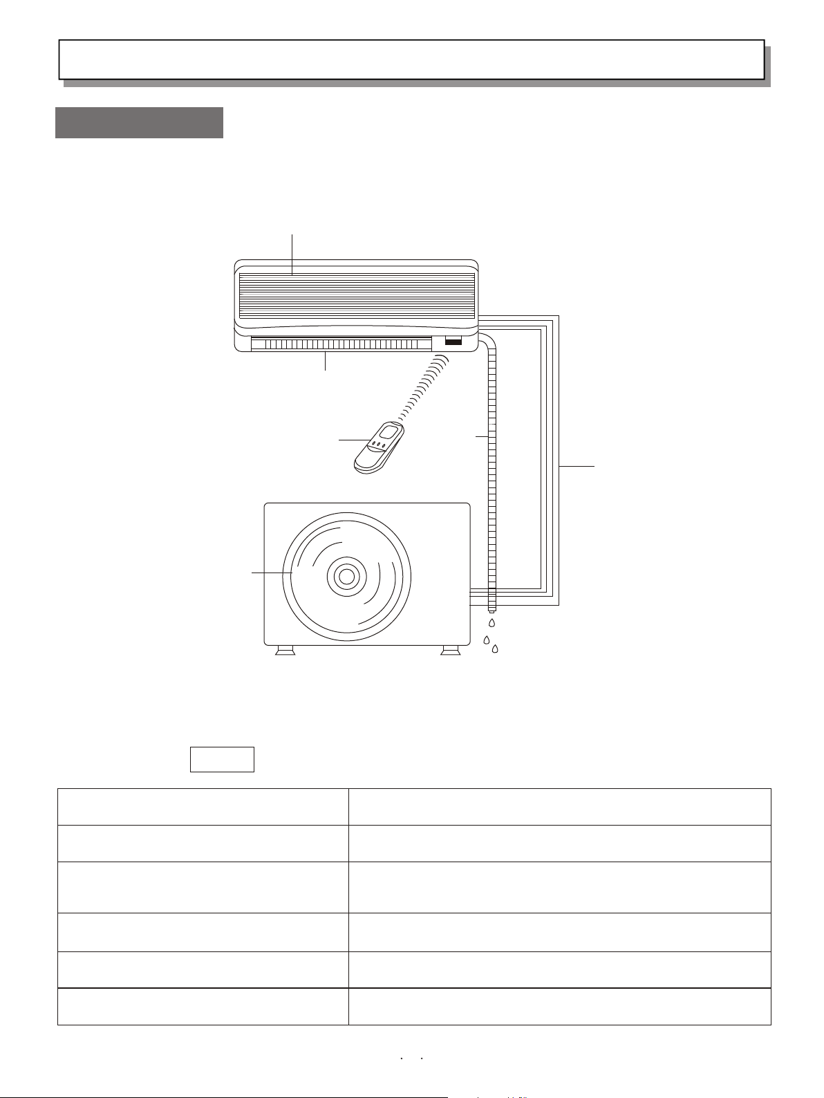
Composition of the Air Conditioner
1.Diagram of Structure
Air intake grille
INDOOR UNIT
Air outlet
Remote
control
unit
OUTDOOR UNIT
Air outlet
NOTE
Remote Control Unit
Refrigerant Tubes
Outdoor(Condensing)Unit
This air conditioner consists of an indoor unit and an outdoor unit. You can
control the air conditioner with the remote control unit.
Air Intake
Air Outlet
Drain Hose
Drain hose
Refrigerant tubes
Air from the room is drawn into this section and passes
through air filters which remove dust.
Conditioned air is blown out of the air conditioner through
the air outlet.
The wireless remote control unit controls power ON/OFF,
operation mode selection, temperature, fan speed, timer
setting, and air sweeping.
The indoor and outdoor unts are connected by copper
tubes through which refrigerant gas flows.
The outdoor units contains the compressor, fan motor, heat
exchanger coil, and other electrical components.
Moisture in the room condenses and drains off through this hose.
3
Page 6
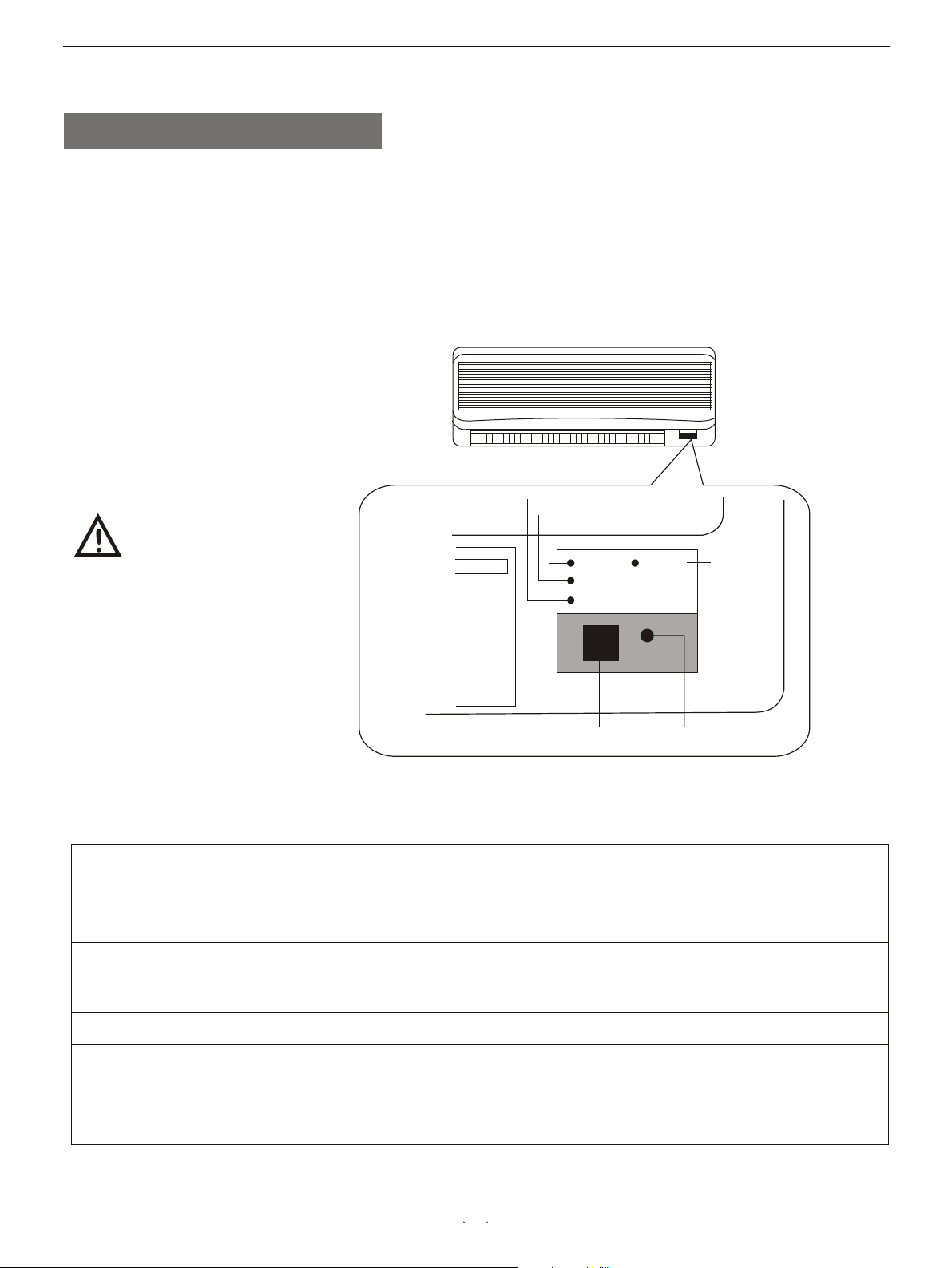
2.Introduction of the Indoor ControI Unit
IMPO RTAN T:
Avoi d usin g radi o
equi pmen t s u ch a s mobi le
p h o n e n e a r
(wi t hin 1 m) t h e
indo or uni t.
Some ra dio e qui p ment
m a y
c a use maIf unct ion of t he
unit .
INDOOR UNIT
OPE RAT ING l a mp
TIM ER la mp
POW ER la mp
PO WE R
TI ME R
OP ER ATI NG
HI P OW ER
ON /O FF
HI GH
PO WE R
la mp
If t h e t rou b Ie
h a p p e n s , d i s -
REMOTE CONTROL
receiver
POW ER la m p
TIM ER la mp
OPE RAT ING l a mp
HIP O WER l a mp
ON/ O FF bu t ton
REMOT E CO NT RO L re ce iver ON /O FF b ut to n
This section picks up infrared signals from the remote
c o n t r o l u n i t
(transmitter)
This lamp lights when the air conditioner is in
t h e o p e r a t i o n
mode.(But the compressor may not run at this time.)
This lamp lights when the system is being controlled by the
timer.
This lamp lights when the outdoor unit is electrified.
This lamp lights when the air conditioner run efficiently.
This button is set for emergent state.Please use the remote
c o n t r o l
unit to operate the air conditioner in the common state. If
y o u h a v e
lost the remote control unit or it has trouble, se this
u
4
Page 7
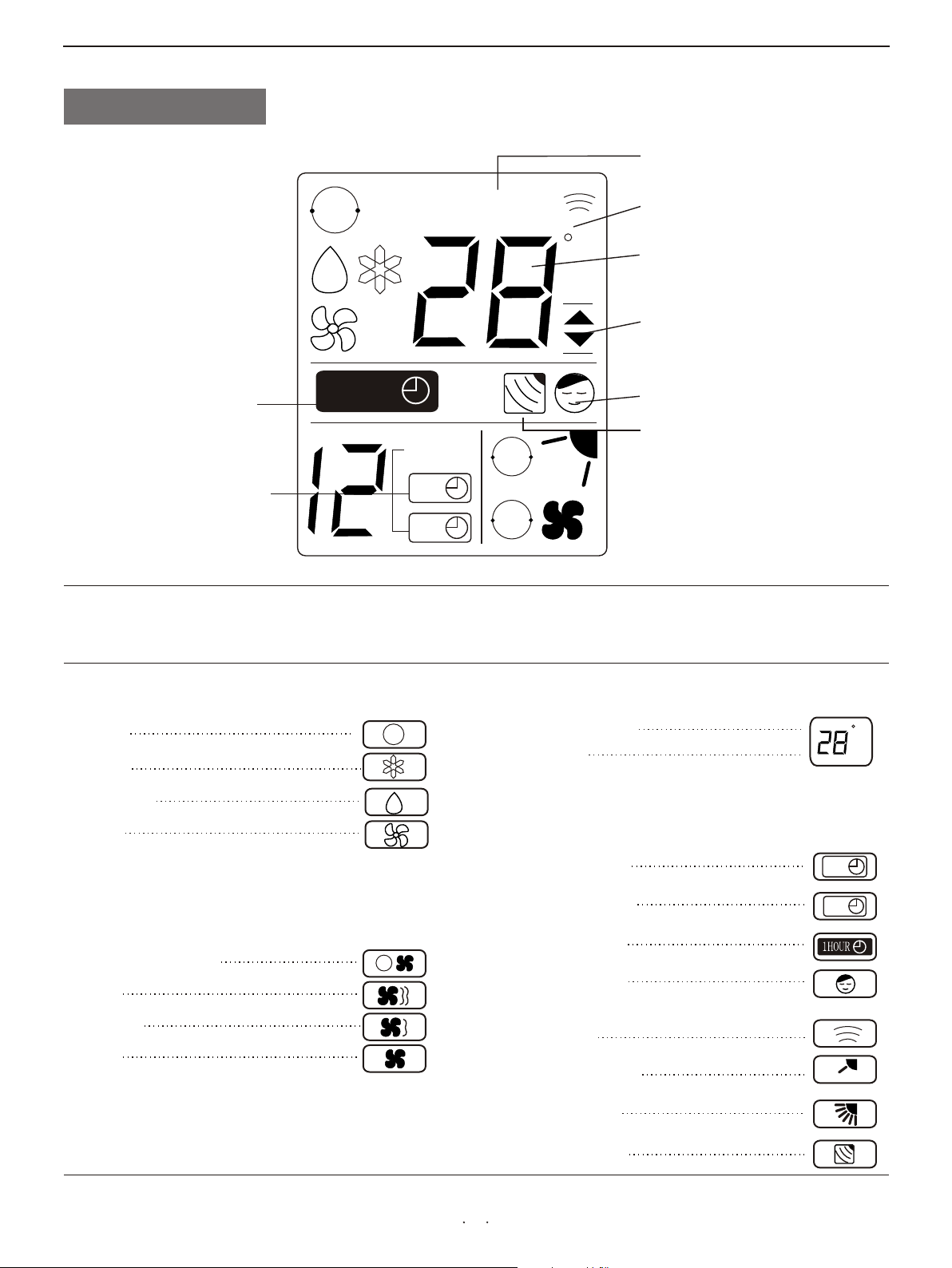
3.Introduction of Display
Displayed when setting temperature
Displayed when one-hour
OFF timer is enable
Displayed when setting timer
AUTO
1HOUR
S E T T E M PS E T T E M P
1小 时
HOUR
ON
OFF
Symbols
AUTO
AUTO
C
Displayed when transmitting data
Displayed when temperature is shown
Displayed when temperature setting
is at the upper or lower allowable
limits
Displayed when Night Setback is
running
Displayed when main unit sensor is in
use
(1) Operation mode
AUTO
COOL
MILD DRY
FAN
(2) Fan speed
Automatic operation
HIGH
MEDIUM
LOW
(3) Set temperature
16-30℃
AUTO
AUTO
When set to 28℃
Current temperature
indication
(4) Timer
12-hour ON Timer
12-hour OFF Timer
1-hour OFF Timer
(5) NIGHT SETBACK
(6) Confirmation of
transmission
(7) Flap angle indication
(8) Sweep indication
(9) Indoor unit sensor
C
ON
OFF
5
Page 8
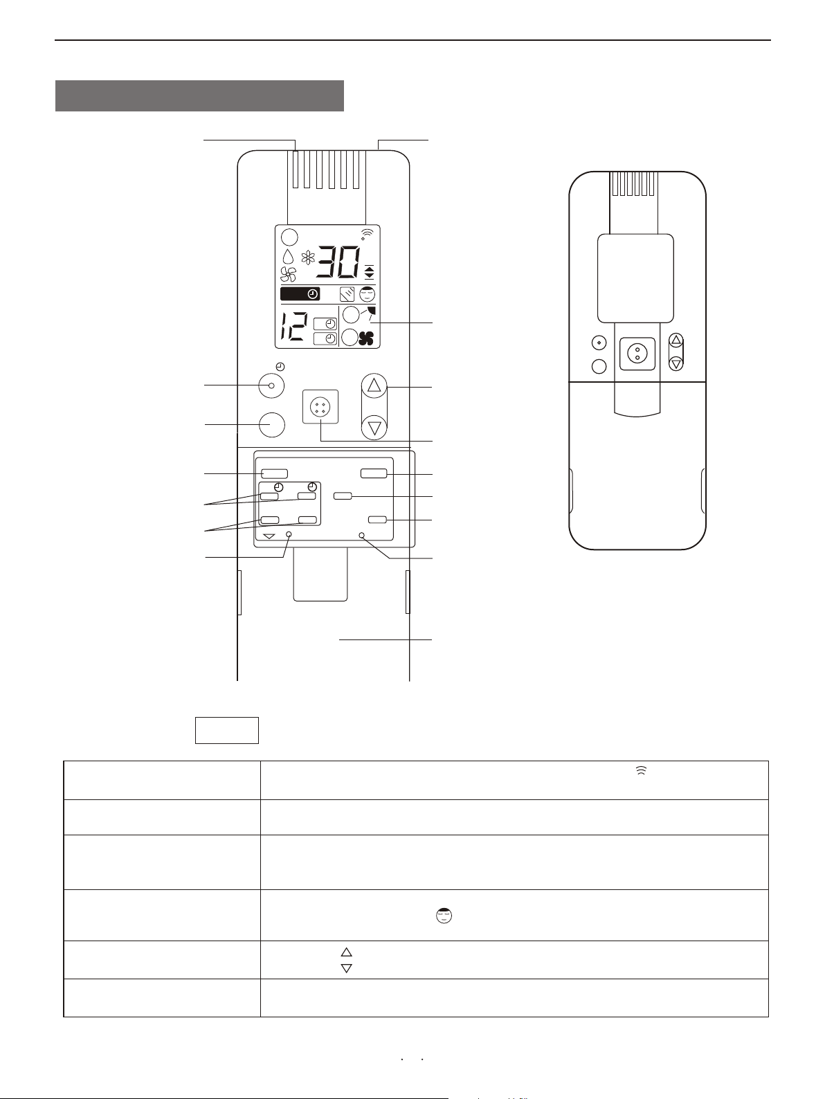
4.Introduction of the Remote control Unit
SENSOR
1 HR. TIMER button
HIGH POWER button
FLAP button
TIMER ON/OFF button
TIMER SET/CANCEL
button
A/C SENSOR button
1 小时
x
1HR
FLAP
ON
预约
BATTERY
SET
POWER
Transmitter
SET TEMP
AUTO
1HOUR1HOUR
HOURHOUR
ON
OFF
ON/OFF
AUTO
AUTO
C
Display
TEMP
TEMP.setting button
HIGH
ON/OFF button
关
OFF
CANCEL
A/C SENSOR
MODE
FAN SPEED
SLEEP
ACL
MODE selector button
FAN SPEED
selector button
NIGHT SETBACK button
ACL button
(Cover closed)
Transmitter
TEMP. Setting
ON/OFF operation
NOT E
SENSOR
Display
SLEEP
button
buttons
button
Battery compartment
(pull off the cover to expose the
batteries.)
The i l lust r atio n abov e pict u res t h e rem o te c o n tro l unit a fter t he co v er ha s
been l ower e d and r emov e d.
When you press the buttons on the remote control unit,the mark appears in
the display to transmit the setting changes to the receiver in the air conditioner.
A temperature sensor inside the remote control unit senses the room
temperature.
Information on the operating conditions is displayed while the remote control
unit is switched on. If the unit is turned off, only the mode that was set
previously is still displayed.
For details, see“Night Setback Mode”. When you press this button, in the
DRY or COOL mode, the mark appears in the display, the remote
control unit will automatically adjust the set temperature to save energy.
Press the button to increase the set temperature.
Press the button to reduce the set temperature.
This button is for turning the air conditioner on and off.
6
Page 9
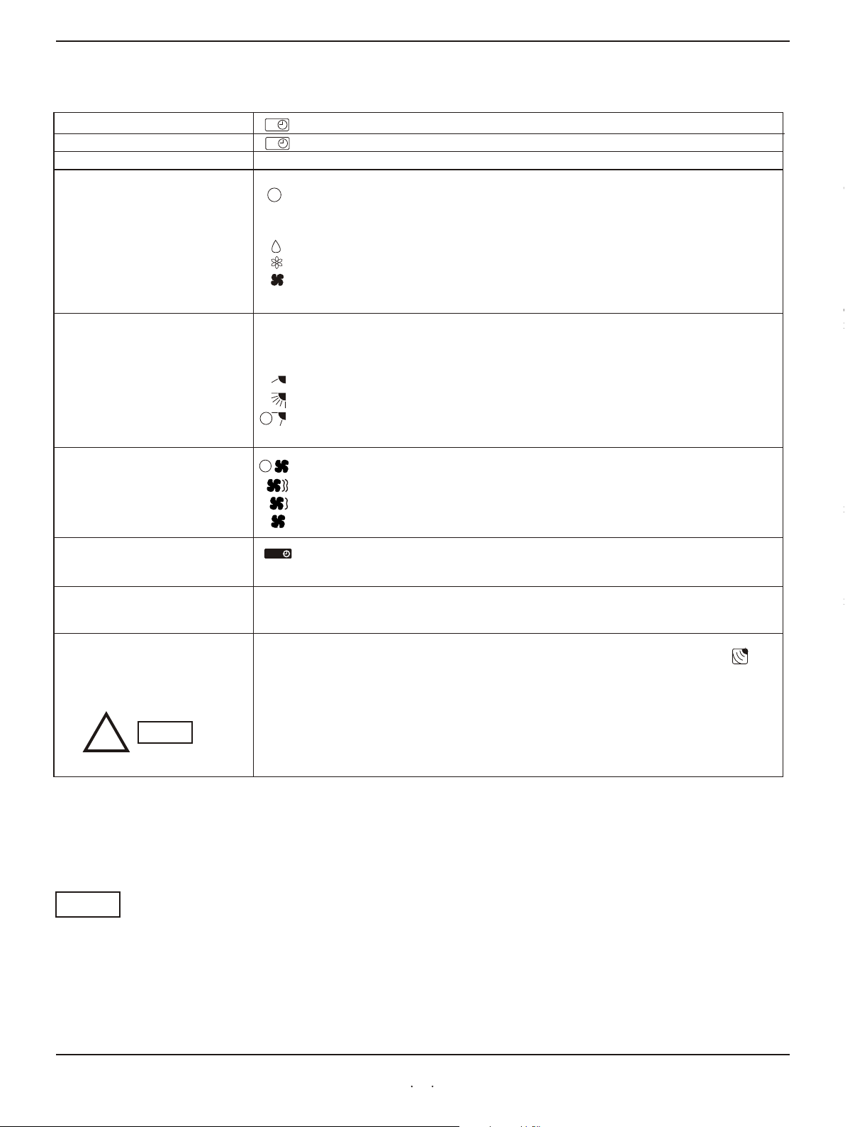
Remote Control Unit(continued)
TIMER ON button
TIMER OFF button
TIMER SET/CANCEL button
MODE selector button
(AUTO)
(DRY)
(COOL)
(FAN)
FLAP button
FAN SPEED selector
button
ON
:The air conditioner starts at the set time.
The air conditioner stops at the set time.
OFF
This button is used to set/cancel the time at which you wish the air conditioner to go on or off.
Use this button to select AUTO, DRY COOL mode.
:When this setting is selected, the air conditioner calculates the difference between the
AUTO
set thermostat and the room temperature and automatically switches to the "COOL"
or "HEATI" mode appropriately.
:The air conditioner reduces the humidity in the room.
:The air conditioner makes the room cool.
:The air conditioner makes the room's temperature suitable.
Press this button either to select to set the airflow
positions manually, or to select the
automatically.
:
:The flap moves up and down automatically.
:Press the FLAP button and set the airflow directions as desired. (refer to Adjust the
Airflow Direction).
AUTO
:The air conditioner automatically decides the fan speeds.
: High fan speed.
:Medium fan speed.
AUTO
:Low fan speed.
:When you press this button, regardless of whether the unit is operating or stopping,
the unit operates for one hour and then shuts down.
:
or
direction to one of the six possible
sweep function, which moves the flap up and down
The airflow direction can be set manually.(six positions)
1 HR TIMER button
(1-HOUR OFF TIMER)
ACL button
A/C SENSOR button
1HOUR1HOUR
Puts the remote control unit into pre-operation status. Always press this button after
replacing the batteries.
When you press this button (use a small-tipped object such as a ballpoint pen), the mark
will appear at the display. And the room temperature is detected by the sensor which is built
into the indoor unit and the air conditioner is controlled accordingly.
If the remote control is located near a heat source, such as a space heater or
indirect sunlight, press the A/C SENSOR button to switch to the sensor in the
indoor unit.
!
Automatic switching between cooling and heating
This unit automatically switches between cooling operation and heating operation according to the difference
between the room temperature and the set temperature.
NOTE
NOTE
The remote control unit sends the temperature signal to the air conditioner regularly at
three minute intervals. If the signal from the remote control unit stops for more than ten
minutes due to the loss of the remote control unit or other trouble, the air conditioner
will switch to the temperature sensor which is built into the indoor unit and control the
room temperature. In these cases, the temperature around the remote control unit may
differ from the temperature detected at the air conditioner s position.
,
7
Page 10

Operation Guide
HOW TO INSTALL BATTERIES
!
NOTE
1. Slide the cover in the direction indicated by the arrow and remove it.
2. Install two AAA alkaline batteries. Make sure the batteries point in
the direction
marked in the battery compartment.
3. Use a thin object such as the tip of a pen to press the ACL button.
ACL button
B
A
Replace the batteries when the remote control unit's display fails to light,
●
or when the remote control unit cannot be used to change the air
conditioner s settings.
●
Use two fresh leak-proof type-AAA alkaline batteries.
● e
In replacing batteri s, follow the instructions as mentioned in the sub-
section How to install Batteries .
●
If you do not use the remote control unit more than 1 month, take out the
batteries.
,
“ ”
HOW TO USE THE REMOTE
CONTROL UNIT
REMOTE CONTROL UNIT
INSTALLATION POSITION
DO NOT
When using the remote control unit, always point the unit's
transmitter head
directly at the air conditioner's receiver.
Air conditioner
(Indoor unit)
Receiver
Remote control
unit
To ensure that the air conditioner operates correctly, DO NOT install the
remote control unit in the following places:
In direct sunlight
Behind a curtain or other places where it is covered
More than 8 meters away from the air conditioner
In the path of the air conditioner's airstream
Where it may become extremely hot or cold
Where it may be subject to electrical or magnetic noise
Where there is an obstacle between the remote control unit and the air
conditioner
(Transmitter head)
8
Page 11

Operation with the Remote Control Unit(continued)
C
AUTO
AUTO
NOTE
STEP 5
1HR
HIGH
POWER
FLAP
ON
SET CANCEL
BATTERY
ON/OFF
OFF
A/C SENSOR
FAN
SPEED
TEMP
MODE
SLEEP
STEP 3
STEP 2
STEP 1
STEP 4
ACL
Check that the circuit breaker on the power panel is turned on and that the operation selector of the indoor
u n i t i s
in the ON position.
If the automatic operation settings of the unit do not meet your needs, press the setting buttons as
d e s c r i b e d
Press the MODE selector button and select the desired mode.
For dehumidifying operation
For cooling operation
STEP 1
For automatic operation
AUTO
For fan operation
STEP 2
STEP 3
To start the air conditioner, press the ON/OFF operation button.
Press the TEMP setting button to change the temperature setting to the desired temperature .
Adjustable temperature range:
30℃ max. 16℃ min.
STEP 4
Set the FAN SPEED selector button to choose the fan speed you want.
AUTO
!
STEP 5
NOTE
If the fan speed is set to (Automatic), the fan speed switches automatically,
according to the difference between the actual room temperature and the set temperature.
Press the FLAP button and set the airflow direction as desired.
To stop the air conditioner, press the ON/OFF operation button again.
9
Page 12

Adjusting the Fan Speed
A. Automatic
Simply set the FAN SPEED selector to the position.
A microcomputer in the air conditioner automatically controls the fan speed when the mode is selected. When
t h e a i r
conditioner starts operating, the difference between the room temperature (RT) and the set temperature (T) is
d e t e c t e d b y
Coo lin g mod e :
When difference between room temperatureand set
temperature is
RT ≥ T+3℃
AUTO
AUTO
FAN SPEED
High
T+3℃ > RT ≥ T+1℃
RT< T+1℃
Mil d dry ing m o de:
When difference between room temperature
and set temperature is
RT ≥ T+5℃
T+5℃> RT ≥ T+3℃
Rt≤T+3℃
Hea tin g mod e :
When difference between room temperature
and set temperature is
RT < T-3℃
T-3℃< RT ≤ T-1℃
Medium
Low
FAN SPEED
High
Medium
Low
FAN SPEED
High
Medium
T-1℃< Rt<T
NOTE
B. Manual
The above table assumes that the sensor on the remote control is being used. If the sensor in the indoor unit is
being used (the indicator is on), actual operation may differ slightly from the operation described in table.
If you want to adjust fan speed manually during operation, just set the FAN SPEED selector
as desired.[ (High), (Medium), or (Low)]
Low
10
Page 13

Adjusting the Airflow Direction
1. Horizontal
!
CAUTION
2. Vertical
The horizontal airflow can be adjusted by moving the vertical vanes with your hands to the
left or right.
When the humidity is high, the vertical vanes should be in the front
position during the cooling or dehumidifying operation. If the vertical
vanes are positioned all of the way to the right or left, condensation may
begin to form around the air vent and drip down.
The vertical airflow can be adjusted by moving the flap with the remote control unit
Do not move the flap with your hands.Confirm that the remote control unit has been
turned on. Then, use the FLAP button to set either the sweep function or one of
the six airflow direction settings.
6
FLAP
ON
OFF
FAN
SPEED
MODE
COOL
and
DRY
5
4
3
SET CANCLE
BATTERY
A/C SENSOR
SLEEP
ACL
SWEEP
HEAT
2
1
A.Sweep function
The flap starts moving up and down to
deliver air over the sweep range.
●The flap automatically closes when the unit is off.
● Use the FLAP button on the remote controller to adjust the position of the
f l a p .
!
!
NOTE
CAUTION
B.Automatic Function
The flap moves up and down automatically
from ⑥ to ③ during the cooling or drying
operation, from ④ to ① during the heating
operation. Referring to the above illustration.
If you move the flap by hand, the flap position according to the remote
controller
and the actual flap position may no longer match.If this happens,shut off
the
Unit, wait for the flap to close, and then turn on the unit again; the flap
position will now be normal again.
11
Page 14

Using the 12-Hour ON and OFF Timer
STEP 2
STEP 3
1.TIMER ON mode
(Example)
HOURHOUR
ON
1HR
ON/OFF
HIGH
POWER
FLAP
OFF
A/C SENSOR
FAN
SPEED
ON
SET
BATTERY
CANCEL
C
MODE
SLEEP
TEMP
ACL
After the length of time set for TIMER ON elapses, the unit begins operating.
The display depicted at left indicates that the air conditioner will begin operating in
three hours.
Setting Procedures:
STEP 1
Press the MODE button and set the desired operation mode and
press the ON/OFF operation button.
STEP 2
Press the timer ON button to set the time at which you want
operation to begin. The time can be set for one to twelve hours,
in one hour steps.
1 2 3....... 12
Press the timer SET button (which advances the time displayed).
STEP 1
STEP 3
● The display changes immediately to its status previous to timer setting, but the
indication remains.
ON
● To check the status of the timer while it is counting down, press the timer SET
button .
STEP 1
STEP 2
2.TIMER OFF mode
(Example)
HOURHOUR
OFF
1HR
ON/OFF
HIGH
POWER
FLAP
OFF
A/C SENSOR
FAN
SPEED
ON
SET
BATTERY
CANCEL
C
MODE
SLEEP
TEMP
ACL
Cancellation procedure: Press the CANCEL button once again.
After the length of time set for TIMER OFF elapses, the unit stops operating.
The display depicted at left indicates that the air conditioner will stop operating in
five hours.
Setting Procedure:
STEP 1
Press the timer OFF button to set the time at which you want
operation to stop.
The time can be set for one to twelve hours, in one hour steps.
1 2 3....... 12
STEP 2
Press the timer SET button (which advances the time displayed).
● The display changes immediately to its status previous to timer setting, but the
indication remains.
OFF
● To check the status of the timer while it is counting down, press the timer SET
button .
Cancellation procedure: Press the CANCEL button once again.
12
Page 15

Using the 1-Hour OFF Timer
This function causes the unit to operate for one hour and then stop, regardless
of whether the unit is on or off when this button is pressed.
The indicator in the display indicates that this function is operating.
Setting procedure:
Regardless of whether the unit is operating or stopped, press the 1 HR .TIMER button.
Appears in the display.
1HOUR1HOUR
Cancellation procedure:
Press the ON/OFF operation button to turn the unit off, wait for the unit to stop operating,
and then press the ON/OFFoperation button again. The 1-Hour Timer function is now
cancelled and the unit operates normally.
1HR
HIGH
POWER
1HOUR1HOUR
ON/OFF
C
AUTO
AUTO
TEMP
1HOUR1HOUR
ON
SET
BATTERY
FLAP
OFF
CANCEL
A/C SENSOR
FAN
SPEED
MODE
SLEEP
ACL
HIGH POWER Operation
C
AUTO
AUTO
1HR
ON/OFF
TEMP
● If, while the 1-Hour Timer function is operating, the 1 HR.TIMER button is
NOTE
pressed once to cancel the function and then again, the unit continues to
operate for one hour from that point in time and then stops.
●If the 1 HR.TIMER button is pressed while the TIMER OFF function operates,the
OFF Timer is cancelled and the unit will stop operating one hour later.
This operation makes higher or lower temperature airflow than usual, in winter or
summer, which makes you feel comfortanble as soon as you go home.
Setting procedure:
Press the High Efficiency button on the remote control unit gently, with a whisper, and
the lamp on the display panel is lighted, so the high efficient operation comes to work. It
may last the longest time of 15 minutes.
HIGH POWER lamp
POWER
TIMER
OPERATING
HI POWER
Cancellation procedures:
Press the HIGH POWER button again, with a second whisper, the lamp is out.
ON/OFF
ON/OFF button
HIGH
POWER
ON
SET
BATTERY
FLAP
OFF
CANCEL
A/C SENSOR
FAN
SPEED
MODE
SLEEP
ACL
13
Page 16

Night Setback / Simultaneous Use Energy Saving
●Night Setback Mode
Night Setback Mode is used for saving energy. Press the SLEEP
button
in operation. The mark appears in the display. To
C
NOTE This function loses in automation or airflow mode.
AUTO
AUTO
1HR
HIGH
POWER
FLAP
ON
SET CANCEL
BATTERY
ON/OFF
OFF
A/C SENSOR
FAN
SPEED
TEMP
MODE
SLEEP
ACL
Special Remarks
A.In Cooling and DRY Mode:
When the night setback mode is selected, the air
conditioner automatically raises the temperature,
setting 1℃ when 60 minutes have passed, after the
selection was made ,and then another 1℃ after another 60
minutes have passed and at last stops operating
automatically after lasting about 6 hours at this
temperature, regardless of the indoor temperature when
night setback was selected. This enables you to save energy
without sacrificing comfort. This function is
convenient when gentle cooling is needed.
Setting
temperature
1℃
1℃
1 2 3 4 5 6 7 8
Stop operating
Automatically
(Hour)
Press the SLEEP button
Power failure
during operation
Clicking Sound
Clicking sound is
heard from the air
conditioner
Remote Control Unit
● In the event of power failure, the unit will stop. When the power is resumed,
the unit will restart automatically after three minutes.
● In heating or cooling operation. Some plastic parts may expand of shrink due to a
sudden temperature change. In this event, a clicking sound may occur. This is normal,
and the sound will soon disappear.
● The remote control unit sends the temperature signal to the air conditioner regularly
at three-minute intervals. If the signal from the remote control unit stops for more
than ten minutes due to the loss of the remote control unit or other trouble, the air
conditioner will switch to the temperature sensor which is built into the indoor unit
and control the room temperature. In these cases, the temperature around the
remote control unit may differ from the temperature detected at the air conditioner’s
position.
14
Page 17

Operation without the Remote Control Unit
INDOOR UNIT
POWER
TIMER
OPERATING
ON/OFF
HI POWER
ON/OFF button
NOTE
HIGH
POWER
lamp
If you have lost the remote control unit or it has trouble, follow the steps below.
1.When the air conditioner is not running
If you want to turn on the air conditioner, pressing the ON/OFF button once.
2.When the air conditioner is running
If you want to turn off the air conditioner, pressing the ON/OFF button once.
Pressing buttons cannot last too long time, or the air conditioner may
operate abnormally.
Care and Cleaning
!
!
WARNING
CAUTION
1.For safety, be sure to turn the air conditioner off and also to disconnect
the power before cleaning.
2.Do not pour water on the indoor unit to clean it. This will damage the
internal components and cause an electric shock hazard.
Clean the casing and grille of the indoor unit with a vacuum cleaner brush, or
wipe them with a clean, soft cloth.
If these parts are stained, use a clean cloth moistened with a mild liquid
deteraent. When cleaning the grille, be careful not to force the vanes out of
place.
1.Never use solvents, or harsh chemicals when cleaning the indoor unit.
Do not wipe the plastic casing using very hot water.
2.Some metal edges and the fins are sharp and may cause injury if
handled improperly; be especially careful when you clean these parts.
3.The internal coil and other components of the outdoor unit must be
cleaned every year.Consult your dealer or service center.
15
Page 18

Care and Cleaning (continued)
Anti-Mold Filter
How to remove the
anti-mold filter
Anti-Mold Filter
Cleaning
How to replace the
anti-mold filter
The anti-mode filter behind the air intake grille should be checked and cleaned
at least once every three weeks.
1.Grasp both ends of the air intake grille and pull it out and up.
2.Push the anti-mold filter up slightly, and then pull it down.
Air intake grille
Anti-mold filter
Use a vacuum cleaner to remove light dust. If there is sticky dust on the filter,
wash the filter in lukewarm, soapy water, rinse it in clean water, and dry it.
1.With the “前面”(meaning FRONT) mark facing you, slide the anti-mold
filter up into the unit and then lower the handle into the groove on the unit.
2.After installing the anit-mold filter, press the locations marked by the arrows
( ) and close the air intake grille.
Air Clean Filter
(not provided)
!
How to install the air clean
WARNING
filter
Air intake grille
Anti-mold filter
The air cleaning filter removes dust and dirt from the air, and reduces odors and
somke from tobacco.
This air clean filter cannot remove harmful gases or vapors nor ventilate
air in the room. You must open doors or windows frequently when you
use gas or oil heating appliances.Otherwise there is a risk of suffocation
in extreme cases.
The air clean filter needs to be installed behind the anti-mold filter.
1. Remove the anti-mold filter.
2. Install the air clean filter in the position shown in the diagram, with the“前面”
(meaning FRONT)symbol facing the front.
3. Reinstall the anti-mold fillter.
Air
clean
filter
16
Page 19

Tips for Energy Saving
Do not
Do
● Block the air intake and outlet of the unit. If they are obstructed, the unit
will not work well, and may be damaged.
●
Let sunlight directly into the room. Use sunshades, blinds or curtains.
If the walls and ceiling of the room are warmed by the sun, it will take
longer time to cool the room.
●Always try to keep the air filter clean. (Refer to“Care and Cleaning” A
clogged filter will impair the performance of the unit.
●
To prevent conditioned air from escaping, keep windows, doors and any
other openings closed.
.)
Troubleshooting
If your air conditioner does not work properly, first check the following points before requesting service. If it still does not work
properly, contact your dealer or service center.
Trouble Possible Cause
Air c ond iti one r doe s not r un at
all .
1.P owe r fai lur e.
2.L eak age b rea ker t rip ped .
3.L ine v olt age i s too l ow.
4.O per ati on bu tto n is OF F.
5.B att eri es in r emo te co ntr ol un it ha ve
run d own .
1.R est ore p owe r.
2.C ont act s erv ice c ent er.
3.C ons ult y our e lec tri cia n or de ale r.
4.P res s the b utt on ag ain .
5.R epl ace b att eri es.
Remedy
OPE RAT ING l amp f las hes
whi le ai r con dit ion er do es
not o per ate .
Com pre sso r run s but s oon
sto ps.
Poo r coo lin g
per for man ce
Cli cki ng so und i s hea rd fr om
the a ir co ndi tio ner .
OPE RAT ING l amp l igh ts bu t
out doo r uni t wil l not r un.
Tro ubl e in wi rin g sys tem .
Obs tru cti on in f ron t of co nde nse r coi l.
1.D irt y or cl ogg ed ai r fil ter .
2.H eat s our ce or m any p eop le in r oom .
3.D oor s and /or w ind ows a re op en.
4.O bst acl e nea r air i nta ke or a ir
dis cha rge p ort .
5.T her mos tat i s set t oo hi gh fo r
coo lin g(o r too l ow fo r hea tin g).
6.( Out doo r tem per atu re is t oo lo w.)
7.( Def ros tin g sys tem d oes n ot wo rk. )
In he ati ng or c ool ing o per ati on, s ome
pla sti c par ts ma y exp and o r shr ink d ue
to a su dde n tem per atu re ch ang e. In
thi s eve nt, a c lic kin g sou nd ma y occ ur.
1.T he us e of po rta ble t ele pho nes n ear
the a ir co ndi tio ner m ay ca use
dis tur ban ce to i ts no rma l ope rat ion .
2.R est art t he ai r con dit ion er af ter t urn
off t he po wer i mme dia tel y.
Con tac t ser vic er ce nte r.
Rem ove o bst ruc tio n.
1.C lea n air f ilt er to i mpr ove a irf low .
2.E lim ina te he at so urc e if po ssi ble .
3.S hut t hem t o kee p the h eat ( or co ld)
out .
4.R emo ve it t o ens ure g ood a irf low .
5.S et th e tem per atu re lo wer .(o r hig her )
6.( Try t o use a b ack -up h eat er. )
7.( Con sul t you r dea ler .)
Thi s is no rma l, an d the s oun d wil l soo n
dis app ear .
1.T urn o ff th e pow er th en re sta rt th e air
con dit ion er af ter 3 m inu te.
2.T he un it wi ll re sta rt au tom ati cal ly
aft er th ree m inu tes .
17
Page 20

Schematic Diagram
1. Main specifications of the product
Type
Power source
Power consumption of input
P
ower (cooling/heating)
Air flow (high)
Refrigeration dose/consumption
Maximum remote control range/
2. Refrigerant Flow Diagram
Indoor unit
KF-34GWE
a.c 220V/50Hz
(cooling/heating)
1250W
3400W
3
450m /h
R22/1.18kg
angle range
8m/80
。
Outdoor unit
Compressor
Wide tube
Wide
service
valve
Accumulator
Heat exchanger
Narrow
service
Narrow tube
tube
Capillary
Heat exchanger
Strainer
3. Permitted ambient temperature for the air conditioner is following:-7℃~+43℃(GB/T 7725-1996)
18
Cooling cycle
Page 21

4. Electric Wiring Diagram
Outdoor
TERMINAL
TO INDOOR
4 WAY VALUE ASSY
RV
CAPA
1
YLW/GRN
2
3
4
5
BLU
BLU
WHT
GRY
BLK
CAPA
WHT
BLK
RED
RED
R
PNK
BRN
FAN
MOTOR
YLW/GRN
S
COMP
YLW/GRN
C
Intdoor
TRANSFORMER
WHT
WHT
SENSOR SENSOR
1
BRN
2
BRN
1
2
BLK BLK
1 2
1 2
1
2
SEC
1
2
COIL
PRY
SW
1 ~ 8
1 ~ 8
SWITCH ASSY
ROOM
PLUG
BLU
1 2
1 2
SU COM CM FM VA
CONTROL BOARD
PULSE IN
1 2 3
1 2 3
BRN
BLU
YLW/GRN
BLK
BRN
BRN
YLW
YLW/GRN
FLAP
FM
1 3 5
1 3 5
BLK
WHT
FAN MOTOR
RED
RED
RED
WHT
BLK
1
2
3
4
5
EVAPORATOR
TERMINAL
0
1
2
3
4
5
1
2
3
4
5
CAPACITOR
TO OUTDOOR UNIT
RED
ORG
YLW
PNK
BLU
FLAP
MOTOR
19
Page 22

Appendix: Installation
Warning: Carrying out operations displaying this
symbol may result in fatal injury.
Caution: Carrying out operations displaying this
symbol may result in serious injury.
This operation manual has explicit information for
installation and maintenance in most conditions. Contact
the local distributor or after-sales service for further
information.
A. Wiring
Only qualified professionals should carry out wiring
of the appliance.
Disconnect the power supply before completion of
wiring, piping or checking the appliance.
Voltages generated by the appliance is fatal.
Read the electrical schematic diagram and explanation
before installation. Improper installation and earth
connection may result in fatal injury.
Connect the earth as required by local wiring
regulations.
Tightly fasten all the wiring connections to prevent
overheating or fire.
Special power source, switches and sockets are
required for the power supply of the appliance.
Electric meter capacity must be larger than or
equivalent to 16A.
B. Transport
Carefully move the outdoor unit.
C. Installation
----When the appliance is mounted to the ceiling or the
wall,
Make sure that the ceiling or the wall is strong
enough for the appliance.
Make a wood or metal frame to support the appliance if
necessary.
----When the appliance is mounted in a room,
Properly insulate the tube of indoor unit, and make
sure there is no water drops on the appliance or on
the floor.
----When the appliance is installed on a damp or uneven
area,
Make a flat concrete base and place the base under the
outdoor unit.
----When the appliance is installed in an area of strong
winds.
Using anchor bolts and metal frames to fix the
properly covered outdoor unit.
----When the appliance (Model Heat Pump) is installed in
an area of heavy snow.
The outdoor unit must be installed in a position above
the snow accumulation.
D. Connection
Use the shortest tubes possible
Using a flaring method
Smear some refrigeration oil between the flared
surface and the connected tube.
Fasten the nuts with a torque wrench to prevent
leakage of refrigerant.
Check for leakage before trial operation.
E. Maintenance
Disconnect the power before checking the electrical
components and the circuits.
Avoid contact with the moving parts of the appliance.
Clear the site and make sure there is no installation
debris left in the appliance.
F. Other
Keep the room well ventilated during installation.
1. Summary
Read the operation manual before installation and keep
this manual in a safe place.
1-1 Tools
1. Screwdriver
2. Phillips head screwdriver
3. Knife or wire stripper
4. Steel ruler
5. Spirit level
6. Hammer
7. Percussion drill
8. Tube cutter
Tube
9. flarer
Tube
10. bender
11. Adjustable spanner
1-2 Attachment
(see the packing list)
1-3 Parts Package
Copper tubes, components and insulation materials for
the outdoor unit.
1-4 Type of the copper tube and insulation materials
Narrow tube
Wide tube
1. Table 1 indicates that tubes should be cut with an
additional length of 30cm-40cm, to reduce the vibration
from the outdoor unit.
Outside Diameter Thickness Outside Diameter
2. The insulation materials for the copper tubes should
conform to the required length and the wall thickness
should not be less than 8mm.
3. Insulated copper wires should be used for wiring and
the specification should depend on the length.
1-5 Additional materials for installation
1. white tape
2. nails or clips (as required)
3. putty
4. refrigeration oil
5. clips for fixing refrigerant tubes
20
Page 23

Appendix: Installation
2. Location
2-1 Indoor unit
2-2 Outdoor unit
WARNING:
Maintain the required space around the
appliance to prevent overheat.
The area for installation of the appliance should not be in
an area with the following:
Direct sunlight
Heat resource
Inflammable gas
Thick oil fog
The appliance should be installed in an area,
Where the inside space can be evenly conditioned, or
Which is strong enough for the appliance, or,
Having the shortest distance for the copper tubes and
water drain hose, and
Having desired space around the appliance for
maintenance and ventilation.
Min. 5cm
Min. 5cm
Min. 5cm
The outdoor unit should be installed away from the
following:
Heat source and fan exhausting (Figure 3);
Director sunlight;
8
The outdoor unit should be installed in an area with,
Cool temperature;
Good ventilation;
Desired space for air inlet, outlet and maintenance
(Figure 4)
Top obstacle
Tube arrangement
L H Add. Refrigerant Provided Tube(M)
(g/m)
15 7 25 4
L: Maximum length of the tube connecting the indoor unit
and the outdoor unit.
H: The height difference between the indoor unit and the
outdoor unit.
Indoor unit
Height difference(H)
Tube length(L)
Outdoor
unit
CAUTION:
The indoor unit should not be
installed below a height of 1.8m.
Air inlet
Min. 5cm
Strong base (10x40cm concrete or alike). The appliance
Min. 10cm
Air outlet
Valve side
Min. 25cm
Min. 40cm
2
Ground
Air outlet
2m
Min.10cm
Air inlet
2m
Blockage
should be placed not less than 10cm high.
Anchor bolts(4)
Air inlet
Concrete or alike
b t
o
4
0A
mu c
b ut 10c
A o
Min. 10cm
m
Fix the base with anchor bolts to reduce vibration and noise.
21
Page 24

Appendix: Installation
3. Installation of the indoor unit
Rem ove t he wa l l pla te
(1) Rem ove the fi xin g sc rew s a nd keep th em for fut ure us e ( n ot
use d dur ing i n sta lla tio n).
(2) Pre ss the tw o tri ang u lar s ign s o n t he o ute r s hel l a nd
rem ove t he fi x ing c lip .
(3) Rem ove t h e wal l pla te.
Mou nt th e wal l p lat e
(1) Det erm i ne th e c orr ect pos iti on of th e p lat e w ith a lev el
(ne ver u se th e n ake d eye s!) . The p lat e s hou ld be l eve l.
(2)Fix the pl ate with Ф6mm expansion bolts for cement walls and with w ood
screws for wood o r pla ste r walls.
Cau tio n: Ad equ ate s pac e sh oul d be r ese rved for the
ins tal lat i on of the ind oor un i t. To avo id run n ing
noi se and vi b rat ion , t he wal l p lat e sh oul d b e f ixe d
tig htl y on th e w all .
Mak e the w all h o le
Sel ect t he p osi tio n of t he h ole a cco rdi ng t o the pos iti ons o f
the i n doo r and o u tdo or u nit s. T he h ole sh oul d be s lig htl y
low er th an th e w all p lat e.
The di ame ter of th e h ole is 65 mm and th e h ole s h oul d be mad e
wit h the o uts i de en d a lit tle l owe r.
The s ite s hou l d be cl ean ed af ter t he ho l e is ma de.
Le ft tube
ho le center
75
Wa ll p la te
Indoor
Fi xi ng s cr ew
Fi xi ng c li p
Ri ght tube
75
ho le center
Outdoor
Cau tio n: C hec k c aref ull y b efo r e t he hol e is
dri lle d t o m ake sur e t hat t her e i s n o cab l es or
Con nec t the t u bes o f the i ndo or un it
A. Co nne ct th e e lec tri c wir es
(1) Ope n the f r ont p ane l and r emo ve th e c ove r of th e ele ctr ic bo x.
(2) Rem ove t h e wir e cli p in th e ele ctr i c box .
(3) Put in t he wir es f rom the bac k o f th e in doo r un it and pul l th em
out f rom t he fr o nt.
(4) Con nec t t he wi res f irm ly to t he te r min al pa nel .
(5) Fix the wir es w ith the cli p, r epl ace the cov er a nd c los e t he
fro nt pa nel .
Cau tio n: M ake sur e t hat the num ber s of the
ter min als a re the s ame as tho se of the ter min al
B. Co nne ct th e t ube s
(1) Do not l et dus t , d irt , a ir and wat er int o t h e t ube s d uri ng
ins tal lat i on, so nev e r r emo ve t he t ube plu gs i f i n sta lla tio n is
not d ue.
(2) Rem ove th e nut s a t the tu be jo int s o f the in doo r u nit , ali gn the
cen ter o f the t u be fl are ( app ly an ti- f ree zin g oil o n the c one h ead) ,
tig hte n th e con e-s hap ed n uts w ith the han d fi rst , the n ti ght en u p
Fro n t pan e l
An ti -f re ez ing o il
is a pp li ed h er e
Co nn ec ti ng
tu be
Fl ar ed
tu be
Cover
Cau tio n: A voi d lea kag e fro m loo s e c onn ect i on or
dam age o f the f l are f rom o ver -ti ght e nin g.
22
Se t th e ou td oo r uni t
Se t th e in do or u nit
Page 25

Appendix: Installation
(3) Any pa rt of th e dra inp i pe sh oul d b e bel ow the o utl et of th e
ind oor u nit and the j oin ts s houl d be wra p ped wit h wa t erp roo f
adh esi ve ta p e to pr eve nt le aka ge of c o nde nse d wat er.
(4) Bin d the tube s, w ire s and t he d rai n pip e ti ght l y wi th
bin din g tap e , wit h the d rai npi pe un d er th e wir es.
(5) Pre ss dow n t he cl a mpi ng pl a te of the tub e s and fix the
bou nd wi res .
Ins tal l the i n doo r uni t
(1) Pul l th e b o und wi res out thr oug h t he w all hol e a nd p ut t he
ind oor wir es t oge the r wi th t he i ndo o r u n it a t t h e
cor res pon d ing p lac e of th e wal l pla t e.
(2) Hoo k the ind o or u nit o nto the r eta ini ng cl aws o n th e wal l
pla te a nd m ove the uni t b ody sli ghtl y t o ma ke s ure tha t it is
fir m.
4. Installation of the outdoor unit
Mou nt th e out d oor u nit
A. Mo unt t he ou t doo r uni t in th e sel ect e d pla ce.
B. I f t he o utd oor uni t is to be m oun ted on t he wall , t he w all
and the ins tal l ati on b rac ket sho uld h ave suf fic ien t
int ens ity t o b ear t he we igh t of th e out d oor u nit .
(1) Pla ce th e o utd oor u nit c are ful l y ont o the b rac ket .
(2) Fix the u nit ont o th e bra cke t wi th f our b ott om b olt s. T h e
bol ts sh ould h ave a nti -vi bra t ion p ads t o pre ven t f all ing d own
of th e uni t fro m v ibr ati on.
Wire ou tl et
Tubes
Drain pi pe
Tube cl am pi ng p la te
Tubes
Drain pi pe
Wires
Wall pl at e
Tubes
Wires
Drain pi pe
Con nec t the t u bes o f the o utd oor u nit
A. El ect ric w i res
(1) Rem ove t he w ire c ove r of t he o utd oor u nit w ith a
scr ewd riv e r.
(2) Rem ove t h e wir e cli p.
(3) Con nec t the wir es t o th e co rre s pon din g te rmi nal s on the
ter min al pa n el.
Cau tio n: All the " Y " -sh ape d t erm ina l s s hou ld be
plu gge d int o the l i ne b ank a nd th e gro undi ng l oop
ter min al sh o uld b e con nec ted f ull y .
(4) Tig hte n a ll th e scr ews t o ens ure g o od co nne cti on.
(5) Put t he w ire s int o pl ace w ith a cl i p an d re pla c e th e wi r e
cov er.
Cau tio n: N eve r p u t e xtr a wir es into the w ire
com par tme n t t o a voi d d ama ge fro m e ddy i ng flo w
B. Tu bes
The conn ect ion of th e ou tdo or tu bes is th e sa me a s ste ps ( 1 )
and ( 2) of t he in d oor u nit .
Tube cl am pi ng p la te
Wire co ve r
23
Page 26

Appendix: Installation
5.Air purging
Air and moisture remaining in the refrigerant system have undesirable
effects as indicated below. Therefore, they must be purged completely.
·pressure in the system rises
·operating current rises
·cooling efficiency drops
·moisture in the air may freeze and block capillary tubing
·water may lead to corrosion of parts in the refrigerant system
5-1.Air Purging with a Vacuum Pump (for Test Run)
(1)Check that each tube (both narrow and wide tubes between the indoor
and outdoor units have been properly connected and all wiring for the
test run has been completed. Note that both narrow and wide tube
service valves on the outdoor unit are kept closed at this stage.
(2)Using an adjustable wrench or box wrench, remove the valve caps from
the service valve on both narrow and wide tubes.
(3) Connect a vacuum pump and a manifold valve (with pressure gauges) to
the service port on the wide tube service valve.(Fig.A)
Be sur e to use a m anif o ld va l ve fo r a ir pur ging .
CAUTION
I f i t i s n o t a vail able , u se a s top val v e f or
this p urpo se. T h e “ Hi” k n ob of t h e man i fold
valv e must a lway s b e kep t c los e d.
Manifold valve
Pressure
gauge
Indoor unit
Outdoor unit
Lo
Hi
(4)With the “Lo”knob of the manifold valve open, run the vacuum pump.
The operation time for the vacuum pump varies with tubing length and
the capacity of the pump. The following table shows the amount of time
Table
Required time for evacuation when capacity
of 100 liter/h vacuum pump is used
If tubing length is less than 10 m
10 min. or more
If tubing length is more than 10 m
15 min. or more
NOTENOTE
The required time in the above table is calculated based on the
assumption that the ideal (or target) vacuum condition is around 10
mmHg abs.
(5) With the vacuum pump still running, close the “Lo”knob of the
manifold valve. Then stop the vacuum pump.
(6)With the accessory hex wrench, turn the valve stem on the narrow
tube service valve counterclockwise by 90 degrees (1/4 turn) for
10 seconds, and then turn the stem clockwise to close it again.
(Fig.B)
Be sure to completely insert the hex wrench
CAUTION
before attempting to turn the valve.
Vacuum pump
Fig.A
90 (1/4 turn)
Valve cap
Vacuum hose to manifold valve
Fig.B
Narrow tube
Hex wrench
Wide tube
24
Page 27

Appendix: Installation
(7)Leak test all joints at the tubing (both indoor and outdoors) with liquid soap. Bubbles indicate a
leak. Be sure to wipe off the soap with a clean cloth.
(8)With the hex wrench, turn the wide tube service valve stem counter-clockwise to fully open the
valve.
(9)Turn the narrow tube service valve stem counter-clockwise to fully open the valve.
(10)Loosen the vacuum hose connected to the wide tube service port slightly to release the pressure.
Then, remove the hose.
(11)Replace the bonnet and flare nut on the wide tube service port and fasten the flare nut securely
with an adjustable wrench or box wrench. Next, mount the valve cap and tighten it with a torque
wrench (the cap needs to be tightened with the torque of 200kg-cm). This process is very important
to prevent gas from leaking from the system.
(12)Test run the air conditioner.
(13)While the air conditioner is running, apply liquid soap to check for any gas leaks around the
service valves or caps.
(14)If there is no leakage, stop the air conditioner.
(15)Wipe off the soap on the tubing.
This completes air purging with a vacuum pump and
the air conditioner is ready for actual operation.
25
Page 28

PACKING LIST
NO.
1.
2.
3.
4.
5.
6.
7.
8.
9.
10.
11.
12.
13.
THE SY MBOL " *" STA NDS FO R T HE PA R T TO BE PI CKED A ND MAD E P URC H ASE.
INST RUCT ION MA NUAL
INST ALLA TION M ANUA L
REMO TE CON TROL U NIT
NAME
OUTD OOR UN IT
POWE R CABL E
DRAI NAGE E LBOW *
AIR FR ESH FI LTER
INDO OR UNI T
BATT ERY
NAIL S PECI AL
BOLT S PECI AL
WARR ANTY C ARD
COVE R
AMOU NT
1
1
1
1
1
1
1
1
2
6
6
1
1
PACK ING LO CATI ON
OUTD OOR
OUTD OOR
OUTD OOR
OUTD OOR
INDO OR
INDO OR
INDO OR
INDO OR
INDO OR
INDO OR
INDO OR
INDO OR
INDO OR
 Loading...