

Page 1
KF-2302GWEKF-2302GWE
Page 2
Page 3

Features
This air conditioner provides with cooling, and drying functions. Details of the functions
are below; refer to these descriptions when using the air conditioner.
Co m p a c t S i z e
This model is smaller than its
predecessors a n d y e t offers t h e same
capabilities.
Mi c r o p r o c e s s o r C o n t r o l l e d O p e r a t i o n
The i n t e r i o r compartment of t h e remote
control u n i t c o n t a i n s several features
to facilitate automatic operation,
clearly displayed for easy use.
Si m p l e One-touch Wi r e l e s s Remote
Control
The remote control unit has several
fe a t ures t o f acil i t ate a u t omat i c
operation.
12 - H o u r O N o r O F F T i m e r
This timer can be set to a u t o m a t i c a l l y
turn t h e u n i t on or off a t a n y ti m e
with in a 12-hour period.
1- H o u r O F F T i m e r
This timer can be set to a u t o m a t i c a l l y
turn off the unit after one hour.
Ni g h t S e t b a c k
Pressing this S L E E P button changes t h e
se t t i ng o f t h e r o om t em perat u r e
thermostat, allowing you to set the
temperature at w h a t e v e r level that y o u
feel comfortable.
Au t o m a t i c a n d 3 - s t e p F a n S p e e d
Auto/High/Medium/Low
Ai r S w e e p C o n t r o l
This fu n c t i o n m o v e s a f l a p u p and do w n
in t h e air o u t l e t , directing a i r in a
sweeping m o t i o n around t h e room a n d
providing comfort in every corner.
Au t o m a t i c Restart Fu n c t i o n for Po w e r
Failure
Even wh e n power fa i l u r e occurs, preset
programmed operation c a n b e reactivated
once power resumes.
An t i - M o l d F i l t e r
This unit i s e q u i p p e d with an anti-mold
filter that i n h i b i t s t h e growth of mold
and bacteria.
Hi g h P o w e r R u n n i n g
Run with strong power and make you feel
comfortable quickly.
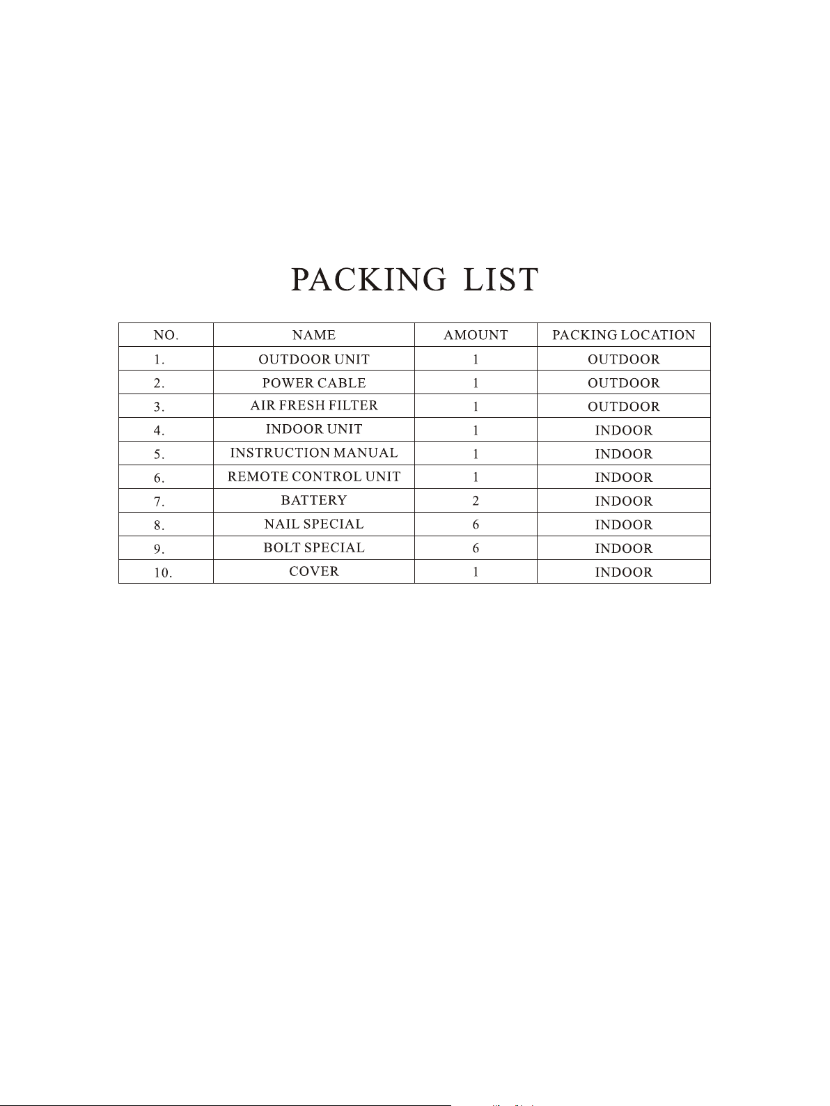
RZA-0-1000-179-SM-A
Page 4
Contents
Pardon not to inform you if the contents of the manual changes.
Alert symbol-------------------------------------------------------------------------------
- - - - - - - - - - - - - - - - - - - - - - - - - - - - - - - - - - - - - 1
Caution statements-------------------------------------------------------------------------
- - - - - - - - - - - - - - - - - - - - - - - - - - - - - - - - 2
Composition of the air conditioner----------------------------------------------------------
- - - - - - - - - - - - - - - - - - - - - - - - - - - - - 3
Operation guide----------------------------------------------------------------------------
- - - - - - - - - - - - - - - - - - - - - - - - - - - - - - - - - - 8
Care and cleaning---------------------------------------------------------------------------
- - - - - - - - - - - - - - - - - - - - - - - - - - - - - - - - - 1 6
Tips for energy saving----------------------------------------------------------------------
- - - - - - - - - - - - - - - - - - - - - 1 8
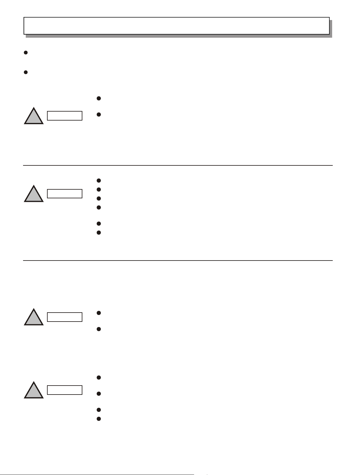
Alert Symbols
WARNING
!
!
CAUTION
The symbol refers to a hazard or an unsafe practice which can result
in severe personal injury or death.
The symbol refers to a hazard or an unsafe practice which can result
in personal injury or product damage.
1
Page 5
Caution Statements
We recommend that this air conditioner be installed properly by qualified installation technicians in accordance with
the installation instructions provided with the unit.
Before installation, check if the voltage of the electric supply in your home or office is the same as the voltage
shown on the nameplate.
Do not install the air conditioner where there are fumes or flammable gases, or
in an extremely humid space such as a greenhouse.
!
WARNING
Do not install the air conditioner where excessively high heat-generating
objects are placed.
Avoid:
WARNING
!
1. Read this manual carefully before using this air conditioner. If you still have any difficulties or problems, consult
your dealer for help.
2. The air conditioner is designed to give you comfortable room conditions. Use this only for its intended purpose as
To protect the air conditioner from heavy corrosion, avoid installing the
outdoor unit where salty sea water can splash directly onto it or in
sulphurous air near a spa.
All wiring must conform to the local electrical codes.
Each unit must be properly grounded.
Wiring must be done by a qualified electrician.
Consider the capacity of the electric current of your electrical kilowatt-hour
meter wires and socket before installation.
Power for this air-conditioner is supplied by individual electrical wire.
There must be at least one ventilation intake in the area where the outdoor unit
is mounted.
!
!
WARNING
CAUTION
Never use store gasoline or other flammable vapor or liquid near the air
conditioner - it is very dangerous.
The air conditioner has no ventilator for intaking fresh air from outdoors. You
must open the doors or the windows frequently when you use gas or oil heating
appliances in the same room, which consume a lot of oxygen from the air.
Otherwise there is a risk of suffocation in an extreme case.
Do not turn the air conditioner on and off from the power mains switch. Use the
ON/OFF operation button.
Do not stick anything into the air outlet of the outdoor unit. This is dangerous
because the fan is rotating at high speed.
Do not let the children play with the remote control unit.
Do not cool or heat the room too much if babies or invalids are present.
2
Page 6

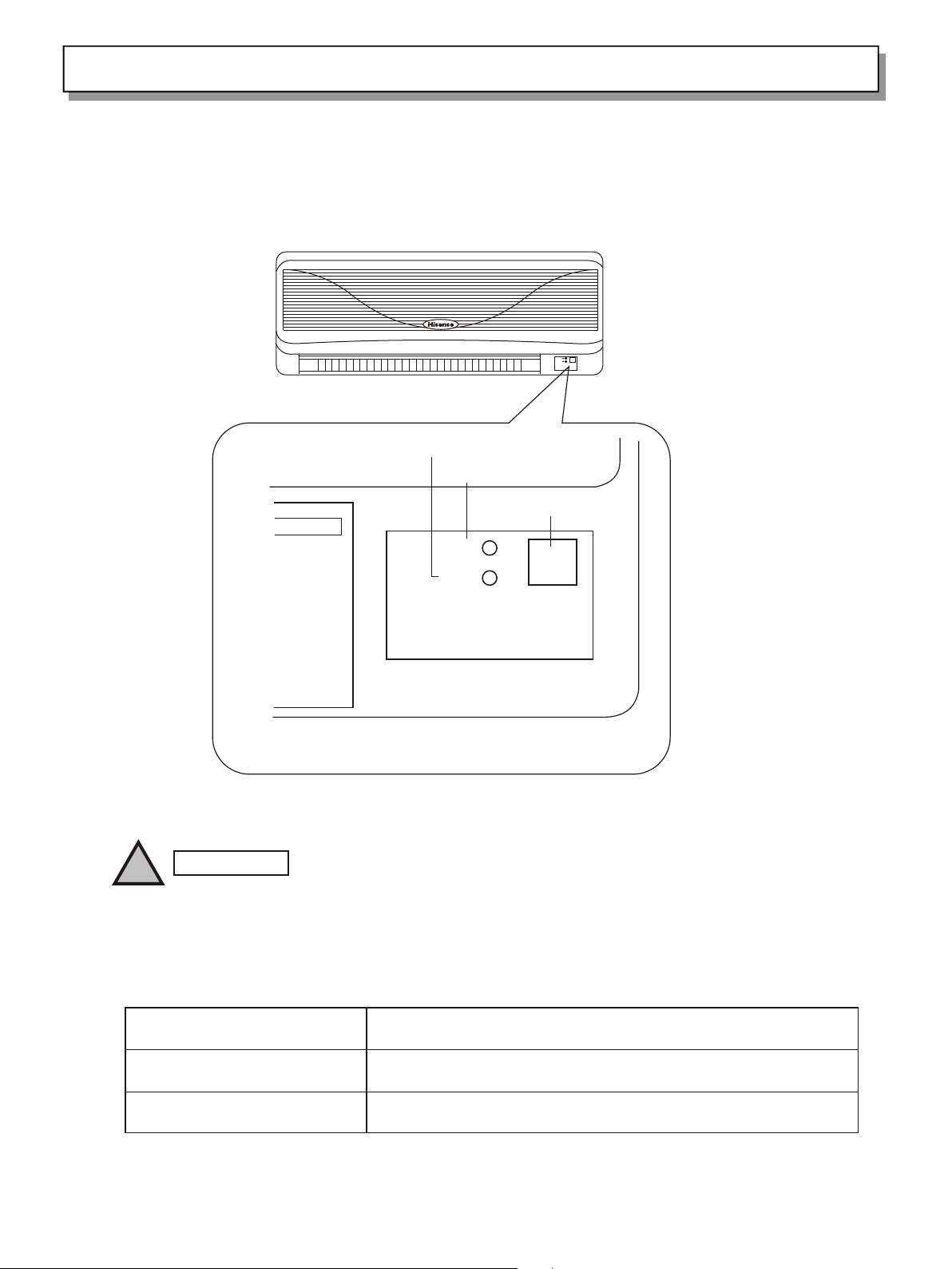
Composition of the Air Conditioner
1. Diagram of Structure
Air intake grille
INDOOR UNIT
Air outlet
Remote
control
unit
Drain hose
Refrigerant tubes
Air outlet
NOTE
Remote Control Unit
Refrigerant Tubes
Outdoor(Condensing) Unit
This air conditioner consists of an indoor unit and an outdoor unit. You can control the
air conditioner with the remote control unit.
Air Intake
Air Outlet
Drain Hose
OUTDOOR UNIT
Air from the room is drawn into this section and passes
through air filters which remove dust.
Conditioned air is blown out of the air conditioner through
the air outlet.
The wireless remote control unit controls power ON/OFF,
operation mode selection, temperature, fan speed, timer
setting, and air sweeping.
The indoor and outdoor units are connected by copper
tubes through which refrigerant gas flows.
The outdoor unit contains the compressor, fan motor, heat
exchanger coil, and other electrical components.
Moisture in the room condenses and drains off through this hose.
3
Page 7
Composition of the Air Conditioner
2. Introduction of the Indoor Control Unit
INDOOR UNIT
TIMER lamp
POWER lamp
REMOTE CONTROL receiver
!
IMPORTANT
POWER
TIMER
Avoid using radio equipment such as mobile phone near(within 1m)the indoor unit.
Some radio equipment may cause malfunction of the unit.
If the trouble happens, disconnect power and restart the air conditioner after a few
minutes.
REMOTE CONTROL
receiver
POWER lamp
TIMER lamp
This section picks up infrared signals from the remote control unit
(transmitter).
This lamp lights when the air conditioner is in the operation mode.
(But the compressor may not run at this time.)
This lamp lights when the system is being controlled by the timer.
4
Page 8

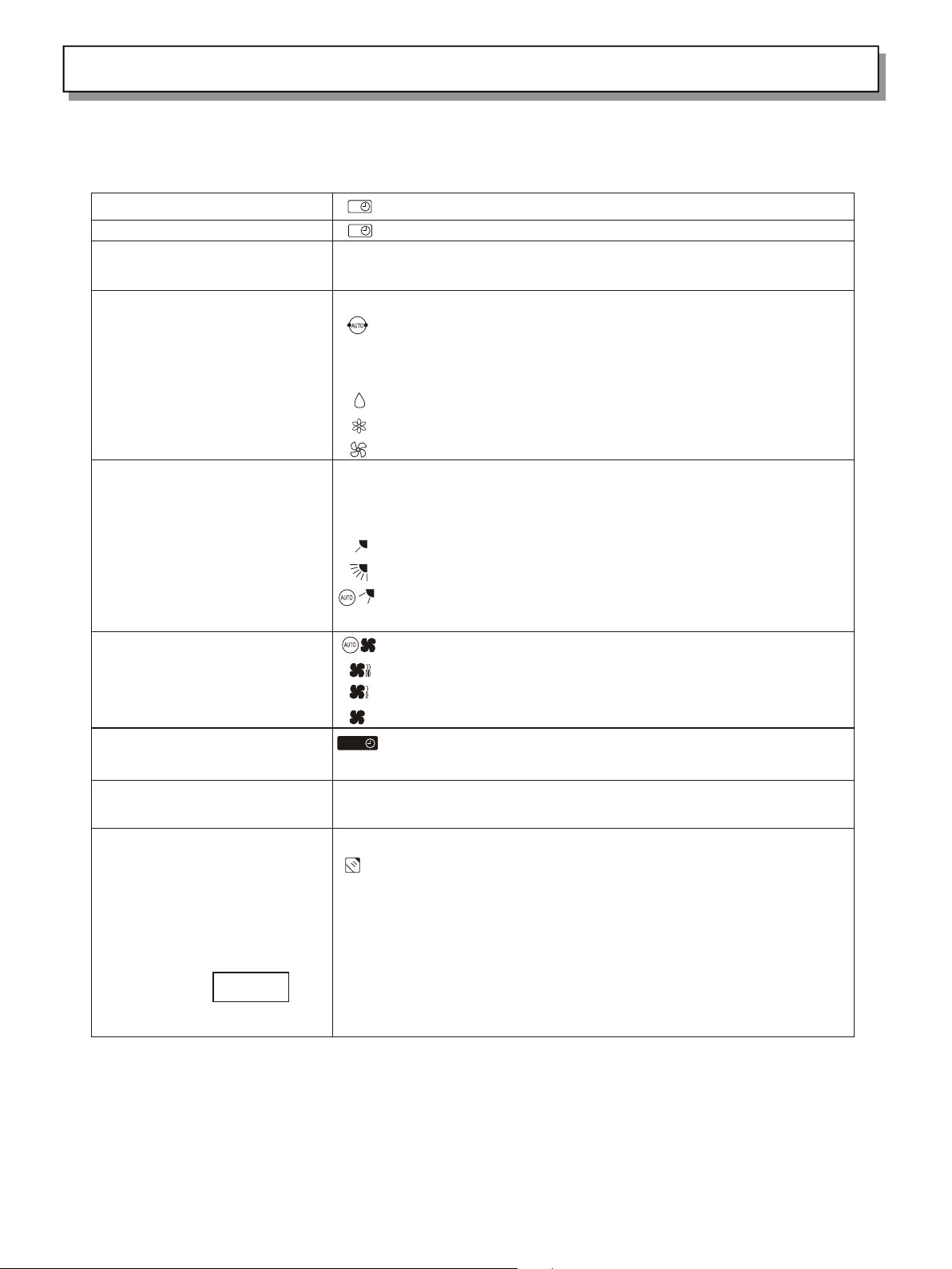
Composition of the Air Conditioner
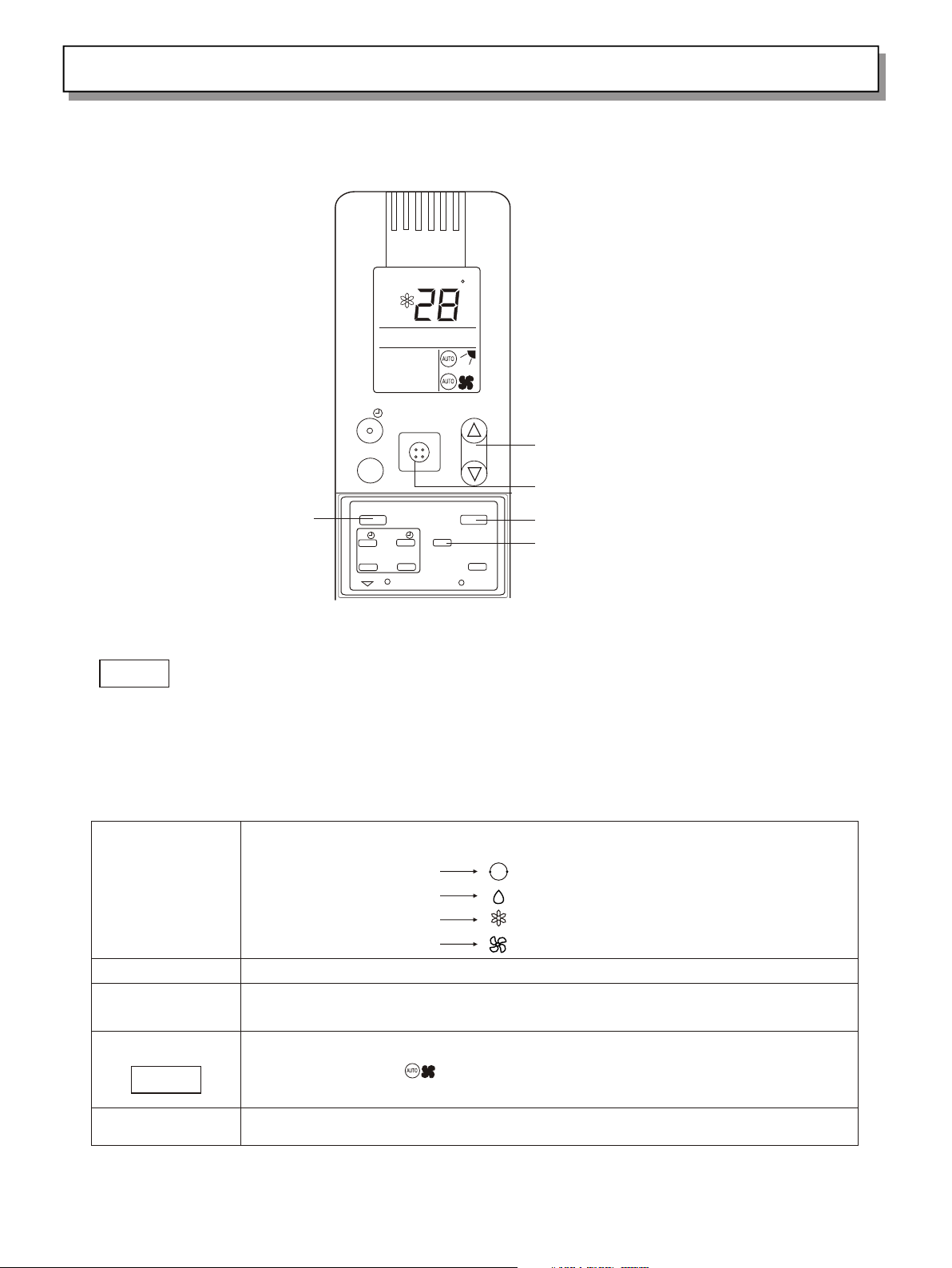
3. Introduction of Display
Displayed when setting temperature;
Displayed when one-hour
OFF timer is enable
Displayed when setting timer
Symbols
(1) Operation mode
AUTO
1HOUR
S E T T E M PS E T T E M P
1小 时
HOUR
ON
OFF
AUTO
AUTO
(4) Timer
C
Displayed when transmitting data
Displayed when temperature is shown
Displayed when the temperature setting
is at the upper or lower limits
Displayed when sleep mode is running
Displayed when indoor unit sensor is in
use
AUTO
COOL
MILD DRY
FAN
(2) Fan speed
Automatic operation
HIGH
MEDIUM
LOW
(3) Set temperature
0
16-30 C
When set to 28 C
Current temperature
indication
0
AUTO
AUTO
C
12-hour ON Timer
12-hour OFF Timer
1 hour timer
(5)NIGHT SETBACK
(6)Confirmation of transmission
(7)Flap angle indication
(8) Sweep indication
(9) Indoor unit sensor
ON
OFF
1HOUR
5
Page 9
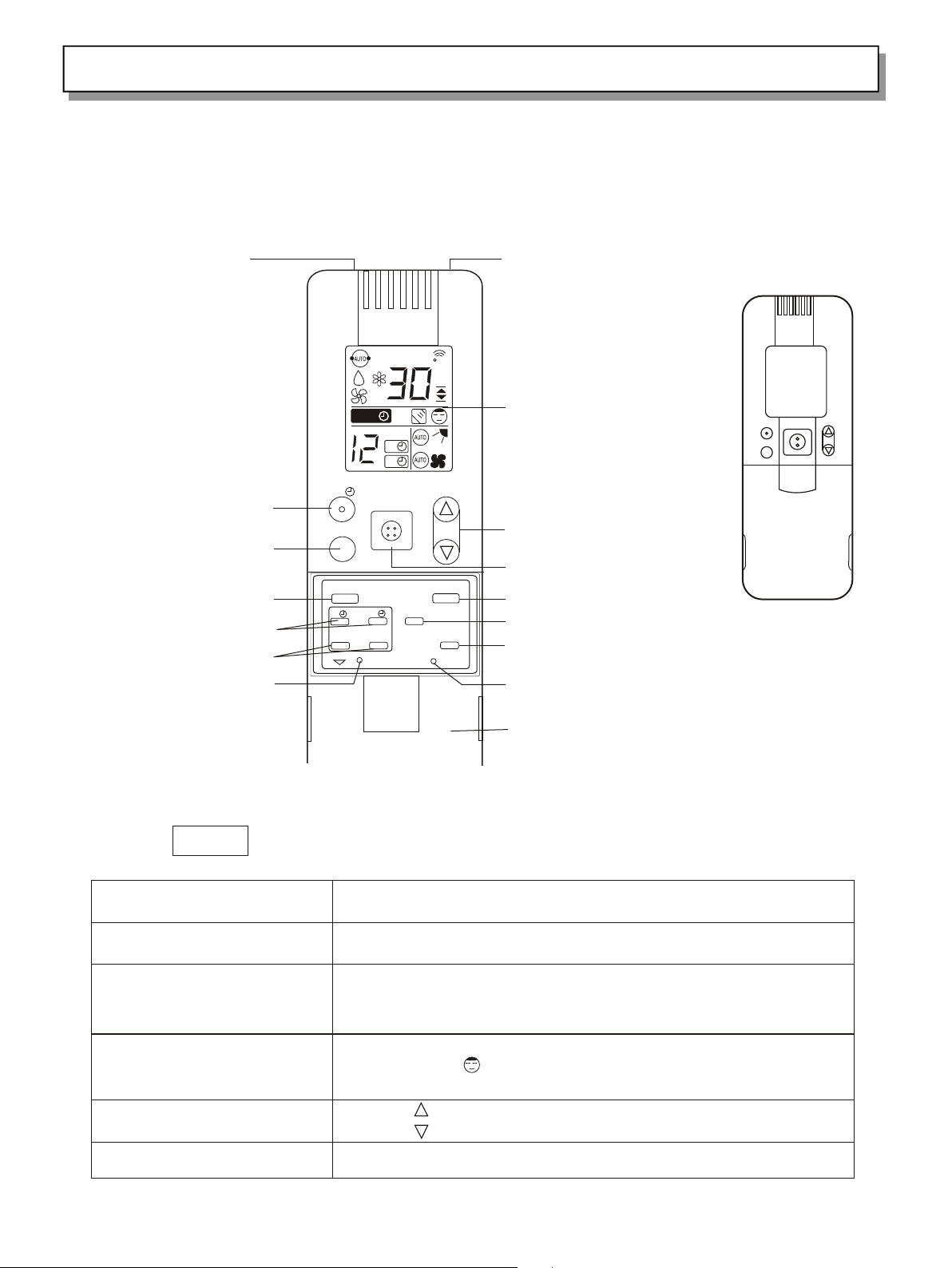
Composition of the Air Conditioner
4. Introduction of the Remote Control Unit
SENSOR
1 HR. TIMER button
HIGH POWER button
FLAP button
TIMER ON/OFF button
TIMER SET/CANCEL button
A/C SENSOR button
SET TEMP
1HOUR
HOUR
ON
OFF
ON/OFF1HR
HIGH
POWER
FLAP MODE
OFF
ON
SET CANCEL
BATTERY
FAN SPEED
A/C SENSOR
C
TEMP
SLEEP
ACL
Transmitter
Display
TEMP. setting button
ON/OFF button
MODE selector button
FAN SPEED selector button
NIGHT SETBACK button
ACL button
(Cover closed)
NOTE
The illustration above pictures the remote control unit after the cover has been lowered
and removed.
Transmitter
SENSOR
Display
SLEEP button
TEMP. setting buttons
ON/OFF operation button
Battery compartment(Pull off the cover to
expose the batteries.)
When you press the buttons on the remote control unit, the mark
a p p e a r s i n
the display to transmit the setting changes to the receiver in the air
c o n d i t i o n e r .
A temperature sensor inside the remote control unit senses the room
temperature.
Information on the operating conditions is displayed while the remote
control unit is switched on. If the unit is turned off, only the mode that
was set previously is still displayed.
For details, see "Night Setback Mode". When you press this button, in the
DRY or COOL mode, the mark appears in the display, the remote
control unit will automatically adjust the set temperature to save energy.
Press the button to increase the set temperature.
Press the button to reduce the set temperature.
6
Page 10
Composition of the Air Conditioner
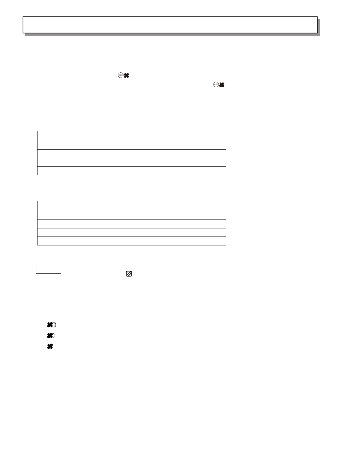
Remote Control Unit (continued)
ON
TIMER ON button
TIMER OFF button
TIMER SET/CANCEL button
MODE selector button
(AUTO)
(DRY)
(COOL)
(FAN)
FLAP button
FAN SPEED selector button
1 HR. TIMER button
(1-HOUR OFF TIMER)
ACL button
A/C SENSOR button
: The air conditioner starts at the set time.
: The air conditioner stop at the set time.
OFF
This button is used to set/cancel the time at which you wish the air
conditioner to go on or off.
Use this button to select AUTO, DRY or COOL mode.
: When this setting is selected, the air conditioner calculates
the difference between the set thermostat and the room temperature
and automatically switches mode appropriately.
: The air conditioner reduces the humidity in the room.
: The air conditioner makes the room cool.
: The air conditioner makes the room's temperature suitable.
Press this button either to select to set the airflow direction to one of
the six possible positions manually, or to select the sweep function,
which moves the flap up and down automatically.
: The airflow direction can be set manually.(six positions)
: The flap moves up and down automatically.
: Press the FLAP button and set the airflow directions as
desired.(refer to Adjust the Airflow Direction).
: The air conditioner automatically decides the fan speeds.
: High fan speed
: Medium fan speed
: Low fan speed
: When you press this button, regardless of whether the unit is
operating or stopping , the unit operates for one hour and then shuts down.
Puts the remote control unit into pre-operation status. Always press this
1HOUR
button after replacing the batteries.
When you press this button (use a small-tipped object such as a ballpoint
pen), the
mark will appear at the display. And the room temperature is
detected by the sensor which is built into the indoor unit and the air
conditioner is controlled accordingly.
NOTE
If the remote control is located near a heat source, such as a space heater
or in direct sunlight, press the A/C SENSOR button to switch to the sensor
in the indoor unit.
7
Page 11
Operation Guide
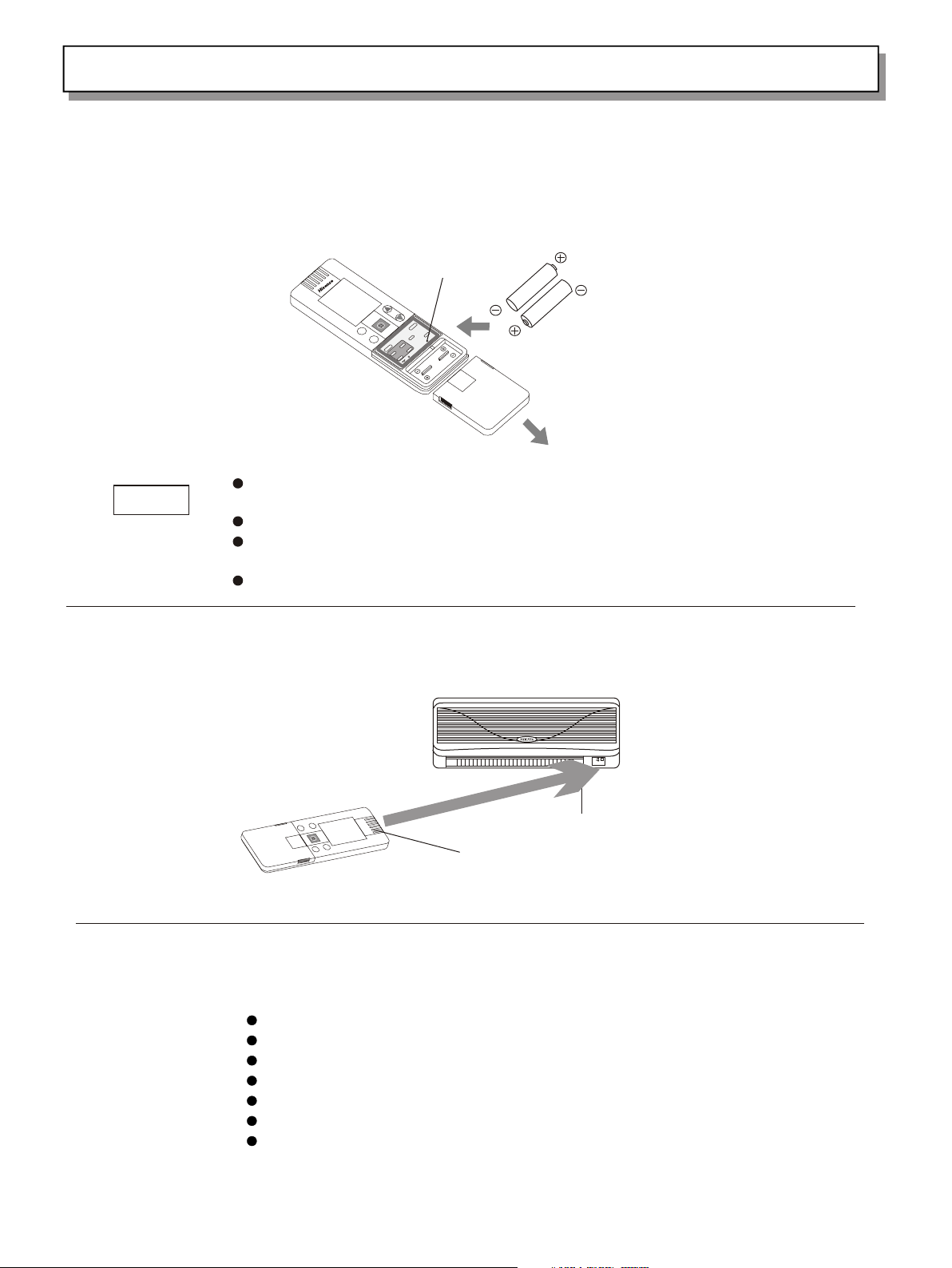
How to Install Batteries
1. Slice the cover in the direction indicated by the arrow and remove it.
2. Install two AAA alkaline batteries, Make sure the batteries point in the direction marked in the battery
compartment.
ACL but t o n
C
B
A
Replace the batteries when the remote control unit's display fails to light, or
NOTE
when the remote control unit cannot be used to change the air conditioner's
settings.
Use two fresh leak-proof type-AAA alkaline batteries.
In replacing batteries, follow the instructions as mentioned in the sub-section
"How to Install Batteries".
If you do not use the remote control unit more than 1 month, take out the batteries.
How to Use the Remote Control unit
When using the remote control unit, always point the unit's transmitter head directly at the air conditioner's
Air con d i t ioner
(Indo o r u n it)
Remot e c o n t rol unit
Recei v e r
关
约
开
预
(Tran s m i t ter head )
Remote Control Unit Installation Position
To ensure that the air conditioner operates correctly, DO NOT install the remote control unit in the following
DO NOT
In direct sunlight;
Behind a curtain or other places where it is covered;
More than 8 meters away from the air conditioner;
In the path of the air conditioner's airstream;
Where it may become extremely hot or cold;
Where it may be subject to electrical or magnetic noise;
Where there is an obstacle between the remote control unit and the air conditioner.
8
Page 12
Operation Guide
Operation with the Remote Control Unit(continued)
C
NOTE
STEP 1
STEP 2
STEP 3
STEP 4
NOTE
STEP 5
TEMP
STEP 3
HIGH
POWER
ON/OFF1HR
STEP 2
STEP 5
FLAP MODE
OFF
ON
SET CANCLE
BATTERY
FAN SPEED
A/C SENSOR
SLEEP
ACL
STEP 1
STEP 4
Check that the circuit breaker on the power panel is turned on and that the operation selector of
the indoor unit is in the ON position.
If the automatic operation settings of the unit do not meet your needs, press the setting buttons
as described below and change the settings as desired.
Press the MODE selector button and select the desired mode.
For automatic operation
AUTO
For dehumidifying operation
For cooling operation
For fan operation
To start the air conditioner, press the ON/OFF operation button.
Press the TEMP setting button to change the temperature setting to the desired
temperature .
Adjustable temperature range: 30℃ max~16℃ min.
Set the FAN SPEED selector button to choose the fan speed you want.
If the fan speed is set to (Automatic), the fan speed switches automatically
according to the difference between the actual room temperature and the temperature
setting.
Press the FLAP button and set the airflow direction as desired.
To stop the air conditioner, press the ON/OFF operation button again.
9
Page 13
Operation Guide
Adjusting the Fan Speed
1. Automatic
Simply set the FAN SPEED selector to the position.
A microcomputer in the air conditioner automatically controls the fan speed when the mode is selected. When the
air conditioner starts operating, the difference between the room temperature (RT) and the set temperature (T) is
detected by the microcomputer which then automatically switches the fan speed to the most suitable level.
Cooling mode:
When difference between room FAN SPEED
temperature and set temperature is
RT ≥ T+3℃ High
T+3℃ > RT ≥ T+1℃ Medium
RT Low
Mild drying mode:
When difference between room FAN SPEED
temperature and set temperature is
RT ≥ T+5℃ High
T+5℃ > RT ≥ T+3℃ Medium
RT Low
< T+1℃
≤ T+3℃
NOTE
2. Manual
If you want to adjust fan speed manually during operation, just set the FAN SPEED selector as desired.
High:
Medium:
Low:
The above table assumes that the sensor on the remote control is being used. If the sensor in
the indoor unit is being used (the indicator is on), actual operation may differ slightly
from the operation described in table.
10
Page 14

Operation Guide
Adjusting the Airflow Direction
1. Horizontal The horizontal airflow can be adjusted by moving the vertical vanes wit your hands to the left or right.
When the humidity is high, the vertical vanes should be in the front position
!
CAUTION
during the cooling or dehumidifying operation. If the vertical vanes are positioned
all of the way to the right or left, condensation may begin to form around the air
2. Vertical
The vertical airflow can be adjusted by moving the flap with the remote control unit. Do not
move the flap with your hands. Confirm that the remote control unit has been turned on. Then,
use the FLAP button to set either the sweep function or one of the six airflow direction
FLAP MODE
OFF
A/C SENSOR
FAN SPEED
SLEEP
ACL
ON
SET CANCLE
BATTERY
A. Sweep function B. Automatic Function
The flap starts moving up and down to
deliver air over the sweep range.
NOTE
The flap automatically closes when the unit is off.
The flap moves up and down automatically
from to station.
SWEEP
6
6
5
O
4
T
U
3
A
3
2
1
!
CAUTION
Use the FLAP button on the remote control to adjust the position of the flap. If you
move the flap by hand, the flap position according to the remote control and the
actual flap position may no longer match. If this happens, shut off the unit, wait
for the flap to close, and then turn on the unit again; the flap position will now
be normal again.
Do not have the flap pointed down during cooling operation. Condensation may begin
to form around the air vent and drip down.
11
Page 15

Operation Guide
Night Setback / Simultaneous Use Energy Saving
Night Setback Mode
Night Setback Mode is used for saving energy. Press the SLEEP button in
operation. The
mark appears in the display. To release the night setback function,
press the SLEEP button again.
ON/OFF1HR
HIGH
POWER
FLAP MODE
OFF
ON
SET CANCEL
BATTERY
FAN SPEED
A/C SENSOR
C
TEMP
SLEEP
ACL
NOTE
This function loses in automation or airflow mode.
In Cooling and DRY Mode:
When the night setback mode is selected, the air conditioner automatically raises
the temperature setting 1 C when 60 minutes have passed after the selection was
made, and then another 1 C after another 60 minutes have passed, and at last stops
0
0
operating automatically after lasting about 6 hours at this temperature,
regardless of the indoor temperature when night setback was selected. This
enables you to save energy without sacrificing comfort. This function is
convenient when gentle cooling is needed.
Setti n g
tempe r a t u re
1℃
1℃
1 2 3 4 5 6 7 8
Stop op e r a ting
Autom a t i cally
(Hour )
Press t h e S L E EP butto n
12
Page 16

Operation Guide
Using the 12-Hour ON and OFF Timer
1. TIMER ON mode:
(Example)
HIGH
POWER
FLAP MODE
STEP 2
STEP 3
ON
SET CANCEL
BATTERY
OFF
A/C SENSOR
HOUR
ON
ON/OFF1HR
FAN SPEED
C
TEMP
SLEEP
After the length of time set for TIMER ON elapses, the unit begins operating.
The display depicted at left indicates that the air conditioner will begin
operating in three hours.
Setting procedures:
STEP 1
Press the MODE button and set the desired operation
mode and press the ON/OFF operation button.
Press the timer ON button to set the time at which you
want operation to begin. The time can be set for one to
STEP 2
twelve hours, in one hour steps.
1 2 3.... . . . 1 2
Press the timer SET button (which advances the time
STEP 1
ACL
The display changes immediately to its status previous to timer setting, but the
indication remains.
ON
STEP 3
displayed).
To check the status of the timer while it is counting down, press the timer SET
button.
Cancellation procedure: Press the CANCEL button once again.
2. TIMER OFF mode:
(Example)
HIGH
POWER
FLAP MODE
ON
STEP 1
STEP 2
SET CANCEL
BATTERY
ON/OFF1HR
OFF
A/C SENSOR
HOUR
OFF
FAN SPEED
C
TEMP
SLEEP
After the length of time set for TIMER OFF elapses, the unit stops operating.
The display depicted at left indicates that the air conditioner will stop
operating in five hours.
Setting procedures:
Press the timer OFF button to set the time at which you
want operation to stop. The time can be set for one to
STEP 1
twelve hours, in one hour steps.
1 2 3.... . . . 1 2
Press the timer SET button (which advances the time
STEP 2
displayed).
The display changes immediately to its status previous to timer setting, but the
indication remains.
OFF
ACL
To check the status of the timer while it is counting down, press the timer SET
button.
Cancellation procedure: Press the CANCEL button once again.
13
Page 17

Operation Guide
Using the 1-Hour OFF Timer
This function causes the unit to operate for one hour and then stop,
regardless of whether the unit is on or off when this button is
pressed.
The indicator in the display indicates that this function is
operating.
1HOUR
ON/OFF1HR
HIGH
POWER
FLAP MODE
OFF
ON
SET CANCEL
BATTERY
FAN SPEED
A/C SENSOR
HIGH POWER Operation
C
TEMP
SLEEP
Setting procedure:
Regardless of whether the unit is operating or stopped, press the 1 HR.
TIMER button.
appears in the display.
Cancellation procedure:
Press the ON/OFF operation button to turn the unit off, wait for the unit to
stop operating, and then press the ON/OFF operation button again. The 1Hour Timer function is now cancelled and the unit operates normally.
NOTE
If, while the 1-Hour Timer function is operating, the 1HR. TIMER button
is pressed once to cancel the function and then again, the unit continues
to operate for one hour from that point in time and then stops.
If the 1HR.TIMER button is pressed while the TIMER OFF function operates,
ACL
the OFF Timer is cancelled and the unit will stop operating one hour
later.
This operation makes higher or lower temperature airflow than usual, in
winter or summer, which makes you feel comfortable as soon as you go home.
ON/OFF1HR
HIGH
POWER
FLAP MODE
OFF
ON
SET CANCEL
BATTERY
FAN SPEED
A/C SENSOR
C
TEMP
SLEEP
Setting procedure:
Press the High Efficiency button on the remote control unit gently, with a
whisper, so the high efficient operation comes to work. It may last the
longest time of 15 minutes.
Cancellation procedure:
Press the HIGH POWER button again, with a second whisper, the high power
operation will be canceled.
ACL
14
Page 18

Operation Guide
Special Remarks
Cooling ( ) operation
Fan ( ) operation
Power failure during operation
Clicking Sound
Clicking sound is
heard from the air
conditioner
Remote Control Unit
In cooling operation, the setting temperature range is from 16 C to 30 C.
Indoor fan has none stop status, even if the compressor stops, the
indoor fan is still working.
In fan operation, the indoor fan speed is set by the remote control unit,
the compressor and outdoor fan do not work.
In the event of power failure, the unit will stop. When the power is
resumed, the unit will restart automatically after three minutes.
In cooling operation, some plastic parts may expand or shrink due to a
sudden temperature change. In this event, a clicking sound may occur. This
is normal, and the sound will soon disappear.
The remote control unit sends the temperature signal to the air
conditioner regularly at three-minute intervals. If the signal from the
remote control unit stops for more than ten minutes due to the loss of the
remote control unit or other trouble, the air conditioner will switch to
the temperature sensor which is built into the indoor unit and control the
room temperature. In these cases, the temperature around the remote
control unit may differ from the temperature detected at the air
conditioner's position.
0 0
Operation without the Remote Control Unit
If you have lost the remote control unit or it has trouble, follow the
steps below.
1. When the air conditioner is not running
If you want to turn on the air conditioner, please open the air intake
grille, the ON/OFF switch will be found, switch the operation selector
to the OFF position, and then to the ON position.
ON/OFF
2.When the air conditioner is running
If you want to turn off the air conditioner,
grille, the ON/OFF switch will be found,
NOTE
Pressing buttons cannot last too long time, or the air conditioner may
operate abnormally.
please open the air intake
switch the operation selector
15
Page 19

Care and Cleaning
For safety, be sure to turn the air conditioner off and also to disconnect the
power before cleaning.
Do not pour water on the indoor unit to clean it. This will damage the internal
components and cause an electric shock hazard.
Clean the casing and grille of the indoor unit with a vacuum cleaner brush, or wipe
them with a clean, soft cloth.
If these parts are stained, use a clean cloth moistened with a mild liquid
detergent. When cleaning the grille, be careful not to force the vanes out of place.
Never use solvents, or harsh chemicals when cleaning the indoor unit. Do not wipe
the plastic casing using very hot water.
Some metal edges and the fins are sharp and may cause injury if handled improperly;
be especially careful when you clean these parts.
The internal coil and other components of the outdoor unit must be cleaned every
year. Consult your dealer or service center.
!
!
WARNING
CAUTION
Care and Cleaning (continued)
Anti-Mold Filter
How to remove the
anti-mold filter
The anti-mold filter behind the air intake grille should be checked and cleaned at
least once ever three weeks.
1. Grasp both ends of the air intake grille and pull it out and up.
2. Push the anti-mold filter up slightly, and then pull it down.
Air intake grille
Anti-mold filter
16
Page 20

Care and Cleaning
Anti-Mold Filter
Cleaning
How to replace the
anti-mold filter
Use a vacuum cleaner to remove light dust. If there is sticky dust on the filter,
wash the filter in lukewarm, soapy water, rinse it in clean water, and dry it.
1. With the " " mark facing you, slide the anti-mold filter up into the
unit and then lower the handle into the groove on the unit.
2. After installing the anti-mold filter, press the locations marked by the
arrows ( )and close the air intake grille.
Air intake grille
Anti-mold filter
Air Clean Filter
(not provided)
WARNING
!
How to install the air
clean filter
The air cleaning filter removes dust and dirt from the air, and reduces odors and
smoke from tobacco.
This air clean filter cannot remove harmful gases or vapors nor ventilate air in
the room. You must open doors or windows frequently when you use gas or oil heating
appliances. Otherwise there is a risk of suffocation in extreme cases.
The air clean filter needs to be installed behind the anti-mold filter.
1. Remove the anti-mold filter.
2. Install the air clean filter in the position shown in the diagram, with the "
"(meaning FRONT) symbol facing the front.
3. Reinstall the anti-mold filter.
Air clean filter
17
Page 21

Tips for Energy Saving
Do not
Do
Block the air intake and outlet of the unit. If they are obstructed, the unit will not work well,
and may be damaged.
Let sunlight directly into the room. Use sunshades, blinds or curtains. If the walls and
ceiling of the room are warmed by the sun, it will take longer time to cool the room.
Always try to keep the air filter clean.(Refer to "Care and Cleaning".)A clogged filter will
impair the performance of the unit.
To Prevent conditioned air from escaping, keep windows, doors and any other openings closed.
Troubleshooting
If your air conditioner does not work properly, first check the following points before requesting service. If it
still does not work properly, contact your dealer or service center.
Trouble Possible cause
Air c o n dition e r does n o t
run at al l .
Compr e s s or run s but so o n
stops .
Poor co o l i n
g perfo r m a nce
Click i n g s o u nd is h eard
from th e a i r c onditio n e r
1.Pow e r f a ilure.
2.Lea k a g e breaker t r i p ped.
3.Lin e v o l tage is too l o w .
4.Ope r a t ion butto n i s O F F.
5.Bat t e r ies in r e m o t e contro l
unit ha v e
run dow n .
O b s t r u c t i o n i n f r o n t o f
conde n s e r coil.
1.Dir t y o r c logged ai r f i l ter.
2.Hea t so u r c e o r m a n y p e ople in
room.
3.Doo r s a n d/or wind o w s a re open.
4.Obs t a c le near air i n t a ke or air
disch a r g e port.
5.The r m o stat is set t o o h i gh for
cooli n g .
I n c ool i n g o p e rat i o n, s o me
plast i c parts m ay e x pand or
s h r i n k d u e t o a s u d d e n
temp e r a t u r e c h a n g e . I n t h i s
Remedy
1.Res t o r e p ower.
2.Con t a c t s ervice c e n t e r.
3.Con s u l t y our e l e c t rician o r
deale r .
4.Pre s s t h e b utton ag a i n .
5.Rep l a c e b atteri e s .
Remov e o b s t ructio n .
1.Cle a n air f i l ter to impro v e
airfl o w .
2 . E li m i na t e h eat s o ur c e i f
possi b l e .
3.Shu t t h e m t o keep the c o l d o u t.
4.Remove i t t o ensure g o o d
airfl o w .
5.Set t h e t e m peratu r e l o w er.
This is no r m al, and the so u nd
will so o n d i s appear .
18
Page 22

Schematic diagram
1. Main specifications of the product
Type
Power source
Range of the voltage
Rated power input
Capacity
Air flow(high)
Refrigeration dose/consumption
Maximum remote control range/angle range
Maximum length of connect tube
2. Refrigerant Flow Diagram
Indoor unit Outdoor unit
Wide
tube
Wide tube
KF-2302GWE
AC 220V 50Hz
AC 198 ~ 242V
kW
0.84
2.30kW
~
3
340m /h
R22/0.52kg
。
8m/80
15m
Accumulat tor
Compressor
Heat exchanger
Narrow
tube
3. Permitted ambient temperature for the air conditioner is as following: 18 C~43 C.
Narrow tube
Capillary tube
Strainer
0 0
19
Heat exchanger
Page 23

Schematic diagram
4. Electric Wiring Diagrams
Outdoor
TERMINAL
TO INDOOR
CAPA
YLW/GRN
1
2
3
4
5
BLK
WHT
CAPA
GRY
WHT
RED
RED
BLK
R
PNK
BRN
FAN
MOTOR
YLW/GRN
S
COMP
YLW/GRN
C
Indoor
POWER TRAN
COI
WHT
WHT
SENSOR
POWER SOCKET
BRN
SENSOR
YEL/GRN
BLU
YEL/GRN
EVAPORATOR
YEL/GRN
1
2
3
1
TERMINAL PANEL
BRN
BLK BLK BLK BLK
1 2
1 2
1 2
1 2
1
1
BRN
2
2
BRN
SEC
1
1
2
2
ROOM
COIL
CONTROL BOARD
PRY
DISPLAY
1 ~ 5
1 ~ 5
DISPLAY
PANEL
BLU
ACIN2
ACIN1
PULSE IN
1 2 3
1 2 3
BRN WHT BLK
CM
BLU RED YEL
RED
FLAP
FM
1 3 5
1 3 5
FAN
MOTOR
1
2
3
4
5
BLU
2
3
TERMINAL PANEL
RED
1
ORG
2
YEL
3
PUR
4
BLU
5
STEP
MOTOR
CONECTION WITH
OUTDOOR UNIT
20
Page 24

Appendix: Installation
1. SUMMARY
1.1 Notice
This operation manual has explicit information for
installation and maintenance in most conditions.
Contact the local distributor or after-sales service
for further information.
1) Wiring notice
Only qualified professionals should carry out wiring
of the appliance.
Disconnect the power supply before completion of
wiring, piping or checking the appliance.
Voltages generated by the appliance is fatal.
Read the electrical schematic diagram and explanation
before installation. Improper installation and earth
connection may result in fatal injury.
Connect the earth as required by local regulations.
Tightly fasten all the wiring connections to prevent
overheating or fire.
Special power, switches and sockets are required for
the power supply of the appliance.
Electric meter capacity must be larger than or
equivalent to 10A.
Remark per EMC Directive 89/336/EEC
To prevent flicker impression during the start of the
compressor (Technical Process) and the adversely
influence caused by the 2 harmonics of compressor
following installation conditions do apply
1. The power connection for the air conditioner has to
be done at the main power distribution. This
distribution has to be of a low impedance is reached at
32A fusing point.
2. No other equipment has to be connected to this power
line.
3. For the detailed installation acceptance please refer
to your contract with the power supplier, if
restrictions do apply for products like washing
machines, air conditioners or electrical ovens.
4. For the details of the power of air conditioner,
please refer to the rating plate of the product.
5. For any question contact your local dealer.
2). Transport
Carefully move the outdoor unit.
3). Installation
----When the appliance is mounted to the ceiling or the
wall,
Make sure that the ceiling or the wall is strong
enough for the appliance.
Make a wood or metal frame to support the appliance if
necessary.
----When the appliance is mounted in a room,
Properly insulate the outdoor unit, and make sure
there is no moisture on the appliance or on the floor.
----When the appliance is installed on a damp or uneven
area,
Make a flat concrete base and place the base under the
outdoor unit.
----When the appliance is installed in an area of strong
winds.
Using firm bolts and metal frames to fix the properly
covered outdoor unit.
----When the appliance (Model Heat Pump) is installed in
an area of heavy snow.
The outdoor unit must be installed in a position above
the snow accumulation.
nd
4). Connection
Use the shortest tubes possible
Using a flaring method
Smear some refrigeration oil between the flared surface
and the connected tube.
Fasten the nuts with a torque wrench to prevent leakage of
refrigerant.
Check for leakage before trial operation.
5). Maintenance
Disconnect the power before checking the
electrical
components and the circuits.
Avoid contact with the moving parts of the appliance.
Clear the site and make sure there is no installation
debris left in the appliance.
6). Other
Keep the room well ventilated during installation.
1.2 Installing instruction
Read the operation manual before installation and keep this
manual in a safe place.
1)Tools
1. Screwdriver
2. Phillips head screwdriver
3. Knife or wire stripper
4. Steel ruler
5. Spirit level
6. Hammer
7. Percussion drill
8. Tube cutter
9. Pipe flarer
10. Pipe bender
11. Adjustable spanner
2) Attachment
(see the packing list)
3) Parts Package
Copper tubes, components and insulation materials for the
outdoor unit.
4) Type of the copper tube and insulation materials
1. Table 1 indicates that tubes should be cut with an
additional length of 30cm-40cm, to reduce the vibration from
the outdoor unit.
Narrow tube
ITEM
Wide tube
Outside Diameter Thickness Outside Diameter
Thickness
KF-2302GWE 6.35mm 0.8mm 9.52mm 0.8mm
2. The insulation materials for the copper tubes should
conform to the required length and the wall thickness should
not be less than 8mm.
3. Insulated copper wires should be used for wiring and the
specification should depend on the length.
5) Additional materials for installation
1. white tape
2. nails or clips (as required)
3. putty
4. refrigeration oil
5. clips for fixing refrigerant tubes
21
Page 25

Appendix: Installation
2. INSTALLATION LOCATION
2.1 Indoor unit 2.2 Outdoor unit
Maintain the required space
!
WARNING
around the appliance to
prevent overheat.
The location for installation of the appliance should not
be in an area with the following:
Direct sunlight
Heat resource
Inflammable gas
Thick oil fog
The appliance should be installed in an area,
Where the inside space can be evenly conditioned, or
Which is strong enough for the appliance, or,
Having the shortest distance for the copper tubes and
water drain hose, and
Having desired space around the appliance for
maintenance and ventilation.(Figure 1)
Min. 5cm
Min. 5cm
Figure 1
Tube arrangement
L H Added Refrigerant Provided Tube(M)
(g/m)
10 7 20 4
Min. 5cm
The outdoor unit should be installed away from the
following:
Heat source and fan exhausting (Figure 3);
Director sunlight;
8
Figure 3
The outdoor unit should be installed in an area with,
Cool temperature;
Good ventilation;
Desired space for air inlet, outlet and maintenance
(Figure 4)
Top obstacle
Air inlet
Min. 10cm
Min. 10cm
Air outlet
Valve side
Min. 25cm
Min. 40cm
2m
2m
Air outlet
Obstacle
L: Maximum length of the tube connecting the indoor unit
and the outdoor unit.
H: The height difference between the indoor unit and the
outdoor unit.
Indoor unit
Height difference(H)
Tube length(L)
Outdoor
unit
Figure 2
* If the length of the tube is exceed 7m, an additional
20g/m of refrigerant should be added per 1m.
The indoor unit should not be
!
WARNING
installed below a height of 1.8m.
Figure 4
Ground
Strong base (10x10cm concrete or alike). The appliance
2
Min.10cm
Air inlet
should be placed not less than 10cm high (Figure 5).
Firm bolts(4)
Min. 10cm
Concrete or alike
bo 40A
u
t
c
m
10cm
u
o t
Ab
Figure 5
Fix the base with firm bolts to reduce vibration and noise.
22
Page 26

Appendix: Installation
3. INSTALLATION OF INDOOR UNIT
3.1 Take off the back cover
1) Release the screw as shown by Figure 6.
Figure 6
2) Take off the back cover.
3.2Drilling
1) Locate the back cover of the indoor unit on the wall,
and determine the desired place with a spirit level and
a ruler. Before drilling, do not fix the back cover
onto the wall.
2) According to direction of the tube ,drilling for tubes
according to the location of the appliance. It is
recommended that the rear right be used for wiring and
drilling.
3) Drill a 65mm hole in the wall (Figure 7), make sure the
Indoor Outdoor
3.4 Install the indoor unit
1) Thread the cable through the hole in the wall, an
additional 13cm of slack power cable should remain
inside the room. (Figure 10)
Back cover
Lining cover
Electrical cable
13cm
2)
Bind the connection cable, drainage hose and
refrigerant tube together tightly with white adhesive
tape; bend the refrigerant tube and make them through
hole of the wall smoothly(figure 11).
Figure 10
Figure 7
Before drilling, make sure that
there is no electric cable or
CAUTION
!
3.3 Installation of the back cover
1) check with a spirit level that the back cover is
installed horizontally. (Figure 8)
2) fix the back cover to the wall with the screws provided.
(Figure 9). Make sure that the back cover is firmly
fixed to he wall.
pipe in the area of the wall where
the hole is to be drilled.
Figure 8
Lining cover
Back cover
Refrigerant tube
Connection cable
Drainage hose
Figure 11
3) Adjust the position of the indoor unit, fixing it
firmly onto the back cover(figure 12).
Figure 9
Figure 12
23
Page 27

Appendix: Installation
3.5 Wiring
(1)Before wiring, make sure the rated voltage indicated
on the nameplate conforms to the local power voltage.
(2)Wiring should be carried out in accordance with the
instructions on the electrical schematic diagram
(Figure 13).
Terminal
Panel of
the indoor
unit
1
2
3
4
5
Figure 13
Terminal
Panel of
the outdoor
unit
1
2
3
4
5
3.6 Wiring connection of the indoor unit
1) Hold pull and open the down right cover and the down
right grille cover.
2) Release the screws and open the wire distribution cover
(Figure 14).
Down right cover
Down right grille cover
Figure 14
3)Connect the wire distribution terminals and
corresponding terminals .(Figure 15)
POWER
TIMER
WARNING
!
Wiring for connection of the indoor unit and the
outdoor unit should be conducted in accordance with
local regulations.
Wiring connections must be fitted firmly.
The electrical wires should not be in contact with any
of the refrigeration tubes, compressor or other moving
parts or components.
The appliance must be connected to a good earth.
4. INSTALLATION OF THE OUTDOOR UNIT
Properly locate the outdoor unit as described by the
Section 2.
If the outdoor unit is to be mounted on the wall ,make sure
that the wall and the support are strong enough for the
appliance.
Wiring Connection
1) Release the fixing screws and take off the side cover.
2) Connect the terminals on the heap pump as required in
the Figure 14 and the
3) Always save an extra 10cm length of the electrical
cable:
4) Earth the appliance according to related regulations
of electrical engineering:
5) Fix the connected terminals with clips and replace the
side cover if the connection is assured according to
the wiring diagram:
Figure 16:
Figure 15
4) Check the connections and then fasten the
distribution cover and replace the down right
grille cover and down right cover finally.
Cover of control box
Connection terminal
Clip
Figure 16
24
Page 28

Appendix: Installation
5.REFRIGERANT TUBE
5.1 Flaring the tube
(1) Cut the tube with a tube cutter to the desired length
(30.50cm is recommended)
(2) Smooth the edge of the copper tube with a reamer or a
file. Hold the pipe vertically with one end downward
to make sure that no copper scraps fall into the
copper tube.
Copper
tube
Figure 17a Figure
17b
(3) Put the tube flarer on the copper tube.
(4) Flare the copper tube ( Figure 18)
Before
Reamer
After
Tapered nuts
Copper tube
5.3 Heat insulation of the refrigerant tube
All refrigerant tubes must be insulated heat with at
least 8mm thick insulation materials. (Figure 21)
Heat insulation materials
Min. 8mm
5.4 Wrapping the tubes
(1) Tie the two refrigeration tubes (including
electrical wire if permitted as regulated), water
drainage hose with white tape.
(2) Wrap half of the tubes outside the room starting
from the end. (Figure 22)
Figure 21
Covering tubes with
heat insulation materials
Thickness
of 8mm
Clip
Figure 18
Note: The flared tube should have:
Smooth internal surface
Smooth edges
Consistent length of the tapered surface
5.2 Connection of the tubes
(1) The sealing tube must be used to prevent dust or
water from getting into the tube.
(2) Before connecting the tube, apply some refrigerant
oil on the surface of the flared tube and connections
to prevent air leakage.( Figure 19)
(3) Align the connecting tube and the flared tube, and
then turn the tapered nut to connect tightly.
(Figure 20)
Application
of refrigerant oil
(4) Fasten the nuts with a spanner.
Figure 19
Flarer
Connecting
tube
Figure 20
Flared tube
(3) Fix the wrapped tubes on the wall in clips with a
space of 120cm.
Note: Do not tie the tubes too tight as this may reduce
heat insulation. Separate water drainage hose and
refrigeration tubes to prevent formation of water
droplets.
5.5 Ending of installation
After completion of wrapping and insulation, seal the
hole on the wall with a suitable sealant.
5.6 Discharge gas
Place appliance A and then B. Air purging method is as
follows:
(1) Turn down the nuts on the wide and narrow tubes.
(2) Loose the nut of the flared wide tube one complete
turn with a spanner.
(3) Turn counterclockwise to open the core of the valve
with a socket screw wrench. Some gas will come out
from under the nut of the flared end of the wide tube.
Tighten the nut 10 to 15 seconds later.
(4) Test for leakage at the tube connector with soapy
water or a meter. If there is no leakage, turn
counterclockwise to open the tube core of the valve
on the wide tube with a socket screw wrench.
(5) Tighten the nuts on the wide , narrow tube valves and
the valve cover.
Please contact the technical service for further
information.
Figure 22
25
Page 29

SPLIT TYPE AIR CONDITIONERSPLIT TYPE AIR CONDITIONER
INSTALLATIONINSTALLATION
Hisense Corporation
MANUALMANUAL
Page 30

Contents
IMPORTANT!
Please Read Before Starting
1.GENERAL
1-1.Tools Required for Installation (not supplied)
1-2.Optional Copper Tubing Kit
1-3.Additional Materials Required for Installation
2.INSTALLATION SITE SELECTION
2-1.Indoor Unit
2-2.Outdoor Unit
3.HOW TO INSTALL THE INDOOR UNIT
3-1.Remove the Rear Panel from the Unit
3-2.Make a Hole
3-3.Install the Rear Panel on the Wall
3-4.Remove the Grille to Install the Indoor Unit
3-5.Shape the Indoor Side Tubing
3-6.Wiring Instructions
3-7.Wiring Instructions for Inter-unit Connections
3-8.Mounting
Page
1
2
2
3
3-9.Drain Hose
4.HOW TO INSTALL THE OUTDOOR UNIT
4-1.Wiring Instructions for Outdoor Unit
5.REFRIGERANT TUBING
5-1.Use of the Flaring Method
5-2.Flaring Procedure with a Flare Tool
5-3.Caution before Connecting Tubes Tightly
5-4.Connecting Tubing between Indoor and Outdoor Units
5-5.Insulation of Refrigerant Tubing
5-6.Taping the Tubes
5-7.Finishing the Installation
6.AIR PURGING
6-1.Air Purging with a Vacuum Pump (for Test Run)
6-2.Service Valve Construction
6-3.Pump Down
9
9
11
RZA-0-1000-881-AZ-D
Page 31

IMPORTANT!
Please Read Before Starting
This air conditioning meets system strict safety and
o p e r a t i n g
standards. As the installer or service person, it is an
i m p o r t a n t
part of your job to install or service the system so it
o p e r a t e s
safely and efficiently.
For safe installation and trouble-free operation, you
must:
· Carefully read this instruction booklet before
b e g i n n i n g .
This symbol refers to a
WARNING
CAUTION
h a z a r d
or unsafe practice which can
result in severe personal
i n j u r y
or death.
This symbol refers to a
h a z a r d
or unsafe practice which can
If Necessary, Get Help
These instructions are all you need for most
i n s t a l l a t i o n s i t e s
and maintenance conditions. If you require help for a
s p e c i a l
In Case of Improper Installation
The manufacturer shall in no way be responsible for
i m p r o p e r
installation or maintenance service, including failure
SPECIAL PRECAUTIONS
When Installing
…
...In a ceiling or Wall
Make sure the ceiling/wall is strong enough to hold the
u n i t s
weight. It may be necessary to construct a strong wood
,
...In a Room
Properly insulate any tubing run inside a room to
p r e v e n t
“
sweating” that can cause dripping and water damage to
...In Moist or Uneven Locations
Use a raised concrete pad or concrete blacks to provide
a
solid, level foundation for the outdoor unit . This
...In an Area with High Winds
Securely anchor the outdoor unit down with bolts and a metal
frame.Provide a suitable air baffle.
...In a Snowy Area (for Heat Pump-type systems)
Insta l l t h e outdoor u n i t o n a raised pl a t f orm that is h i g h er
than dr i f t ing snow. P r o v ide snow ve n t s .
When Connecting Refrigerant Tubing
·Use the flare method for connecting tubing.
·Apply refrigerant lubricant to the matching surfaces of
the flare
and union tubes before connecting them, then tighten
the nut
with a torque wrench for a leak-free connection.
WARNING
When W i r i ng
ELECTRICAL SHOCK CAN CAUSE
SEVERE PERSONAL INJURY OR DEATH.
ONLY A QUALIFIED, EXPERIENCED
ELECTRICIAN SHOULD ATTEMPT TO
WIRE THIS SYSTEM.
·Do not supply power to the unit until all wiring and
t u b i n g a r e
completed or reconnected and checked.
·Highly dangerous electrical voltages are used in this
system. Carefully refer to the wiring diagram and
these instructions when wiring. Improper connections
and inadequate grounding can cause accidental injury
or death.
·Ground the unit following local electrical codes.
· Connect all wiring tightly. Loose wiring may cause
over-
When Transporting
Be careful when picking up and moving the indoor and outdoor
units. Get a partner to help , and bend your knees when lifting
to reduce strain on your back. Sharp edges or thin aluminum
fins on the air conditioner can cut your fingers.
When Servicing
· Turn the power OFF at the main power box (mainsb e f o r e
opening the unit to check or repair electrical
p a r t s a n d w i r i n g .
· Keep your fingers and clothing away from any moving
p a r t s .
· Clean up the site after you finish, remembering to
Others
CAUTION
· Ventilate any enclosed areas when intallation or
t e s t i n g t h e
refrigeration system. Escaped refrigerant gas ,on
c o n t a c t
with fire or heat, can produce dangerously toxic gas.
· Confirm upon completing installation that no
r e f r i g e r a n t g a s
is leaking. If escaped gas comes in contact with a
stove,
1
Page 32

1. GENERAL
This booklet briefly outlines where and how to
install the air conditioning system. Please read
over the entire set of instructions for the indoor
and outdoor units and make sure all accessory
parts listed are with the system before beginning.
1-1.Tools Required for Installation (not supplied)
1. Standard screwdriver
2. Phillips head screwdriver
3. Knife or wire stripper
4. Tape measure
5. Carpenter s level
,
6. Hammer
7. Drill
8. Tube cutter
9. Tube flaring tool
10.Torque wrench
11.Adjustable wrench
1-2.Optional Copper Tubing Kit
Copper tubing for connecting the outdoor unit to
t h e
indoor unit is available in kits which contain the
n a r r o w
and wide tubing, fittings and insulation. Consult
AVOID:
·direct sunlight.
·nearby heat sources that may affect performance of
the unit.
·areas where leakage of flammable gas may be
expected.
·places where large amounts of oil mist exist.
DO:
·select an appropriate position from which every corner
of the room can be uniformly air-conditioned.(High on
a wall is best.)
·select a location that will hold the weight of the unit.
·select a location where tubing and drain hose have the
shortest run to the outside.(Fig.1)
·allow room for operation and maintenance as well as
unrestricted air flow around the unit.(Fig.2)
Ind oor u n it
1-3.Additional Materials Required for Installation
1. Refrigeration (armored) tape
2. Insulated staples or clamps for connecting wire
(See local codes)
3. Putty
4. Refrigeration lubricant
5. Clamps or saddles to secure refrigerant tubing
2. INSTALLATION SITE SELECTION
2-1.Indoor Unit
WARNING
To prevent abnormal heat
g e n e r a t i o n a n d t h e
possibility of fire,do not
place obstacles, enclosures,
and grilles in front of or
s u r r o u n d i n g t h e a i r
conditioner in a way that
may block air flow.
5cm
min.
Dra in ho s e
Out sid e d ra i nag e
Fig.1
5cm min.
Fig.2 (Front V i e w )
5cm
min.
2
Page 33

· i n s tall t he u n i t w i t h i n t h e ma x i m um e l e vation
d i f f e r e n c e
( H ) a b o v e o r bel o w the outd o o r un i t and withi n a
t o t a l
t u b ing length (L ) fr o m t h e o u t d oor unit as
INDOOR UNIT
Elevation
difference(H)
Table 1
Max.A l l o wable Tub i n g
Lengt h a t S h ipment
(m)
Limit o f T u b i ng
Lengt h ( L )
(m)
Tubeing length(L)
OUTDOOR
UNIT
Fig.3 a
Limit o f E l e v ation
Diffe r e n c e (H)
(m)
7.5 20 7 25
CAUTION
For stable operation of the
air conditioner,do not
install wall-mounted type
indoor units less than 1.8m
from floor level.
Required Amount of
Additional Refrigerant
(g/m)*
If total tubing length becomes 7.5
t o 2 0 m
(max.),charge additional refrigerant
(R22) by 25g/m.
No additional charge of compressor oil
is necessary
Indoor unit
Minimum height
from floor level
1.8m
Floor level
Fig.3 b
Wall
2-2.Outdoor Unit
AVOID:
·heat so u r c e s, exhau s t f a n s, etc.( F i g . 4a)
·damp, h u m i d o r uneven l o c a t ions.
Hot air
Outdoor unit
8
Exhaust fan
DO:
·choos e a p l a c e as cool as p o s s i ble.
·choos e a p l a c e that is we l l v e n tilate d .
· al l o w eno u g h room a r o u n d th e unit fo r air
i n t a k e /
exhau s t a n d p ossibl e m a i n tenanc e . ( F ig.4b)
· p r o v ide a so l i d ba s e (c o n c rete b l ock,10× 40cm
b e a m s
Air intake
Min. 10cm
Valve side
Min. 25cm
or e qual), a min i m u m o f 10c m abo v e gro u n d l e v e l
t o
reduc e humidit y and pr o t e ct th e u nit ag a i n st
Min.
5cm
Air discharge
Min. 4
0cm
p o s s i b l e
w a t e r d a m a g e a n d d e c r e a s e d s e r v i c e
life. ( F i g .4c)
· use lu g b o l t s or equa l t o b o l t down un i t
Fig. 4b
3.HOW TO INSTALL THE INDOOR UNIT
3-1.Remove the Rear Panel from the unit
(1)Re m o v e and disca r d t h e set screw o n t h e r ear panel .
(Fig. 5 a )
Air inlet
Concrete
or equal
Locm min
Heat source
Fig.4 a
Obstacle above
2m
Air discharge
Ground
Min.10cm
Air intake
2m
Obstacle
(2)Pr e s s t he 2 marks on t h e f r ame cover a n d
disen g a g e the stati o n a ry tabs fro m t h e f rame.
(Fig. 5 b )
(3)Re m o v e the rear pa n e l .
NOTE
Tubin g c a n b e extende d i n 5 d i rection s a s s h own in
Fig.5 c . S e lect the di r e c tion you ne e d p r oviding t h e
short e s t r un to the out s i d e unit.
·When le f t t u bing is to be d o n e , switch th e d r a in hose
3
b
t
0
cA ou 4
m
Fig. 4c
Set screw only transportation
Abou
cm
0
1
t
Fig. 5a
Page 34

A n d d r a in c a p . ( F o r d et a il s , r e fe r t o
“S w i t ch i ng d ra i n h o se a nd d r ai n ca p” on
3-2.Make a Hole
(1) Place the rear panel from the indoor unit
on th e wall at the lo c a t i o n selected.
Make s u r e the p a n e l is horizontal, u s i n g
a c a r p e n t e r s l e v e l or tape me a s u r e to
,
measure d o w n from t h e ceiling. W a i t until
after c u t t i n g the h o l e b e f o r e attaching
the rear panel to the wall.
(2)Determine w h i c h side o f the u n i t you
should make t h e h o l e f o r tu b i n g a n d
NOTE
In the case of left-rear tubing, use the outside
mark for precise placement of the hose outlet.
(Fig.5d)
(3)Before making the hole, check carefully that no
studs or pipes are directly run behind the spot
to be cut.
Lef t
tub ing
Lef t rear
tub ing
Fig.5 b
Rea r p an e l
mar k s
Right-rear
tubing
(recommended)
Rig ht tubing
Downward tubing
CAUTION
Also avoid areas where electrical wiring or conduits are
located.
The a b o v e p r e c a u t i o n s are also applicable
if tubing goes t h r o u g h t h e w a l l i n an y
other location.
(4)Using a sabre s a w , key hole sa w or h o l e -
cutting d r i l l a t t a c h m e n t , cut a h o l e in
Table 2
Hole Dia.(mm)
65
(5) Measure the thickness of the wall from the
inside edge t o t h e o u t s i d e edge and cut PVC
pipe at a s l i g h t angle 6 mm s h o r t e r t h a n
the thickness of the wall.(Fig.7)
(6)Place the plastic cover over the end of the
pipe (for i n d o o r s i d e only) and i n s e r t the
pipe in the wall.(Fig.8)
3-3.install the Rear Panel on the wall
In case of left-rear, right-rear
Fig.5 d
Hole should be made at a slight downward slant the
outdoor side.
INSIDE
OUTSIDE
Fig.6
PVC pipe (locally purchased)
Be sure to c o n f i r m t h a t t h e w a l l is strong
enough to suspend the unit.
(1)Attach the rear panel to t h e w a l l w i t h t h e
6 nails provided.(Fig.9)
(2)Double c h e c k with a r u l e r or c a r p e n t e r s
,
level that t h e p a n e l i s l e v e l . This is
i m p o r t a n t t o i n s t a l l t h e u n i t
properly.(Fig.10)
(3)Make s u r e the p a n e l is flush a g a i n s t th e
wall. Any s p a c e b e t w e e n the wall a n d u n i t
will cause noise and vibration.
Cut at slight angle
Fig.7
INSIDE
Plastic
cover
Wall
OUTSIDE
PVC pipe
Slight
angle
Fig.8
4
Page 35

Fig.9
·In case of Use of Tapping Screws (for Installing
Remote Control Unit)
Make 4.8mm dia. holes in the wall. Insert rawl
plugs for appropriate mounting screws. (Fig.11)
3-4.Remove the Grille to Install the Indoor Unit
Fig.1 0
4 . 8 m m
dia . ho l e
Raw l p lu g
Basically, these models can be installed and wired
w i t h o u t
removing the grille. If access to any internal part
is needed, follow the steps as given below:
How to remove the grille
(1)Set the flap in the horizontal position.
(2)Unscrew the 2 screws.(Fig.12a)
(3)Remove the grille.(Fig.12b)
(a)Hold both corners of the air intake grille,
t h e n p u l l
out and up to open.
(b)Pull the lower part of the grille toward
you to remove.
(c)Use a standard screwdriver to push up the 3
t a b s t o
remove the grille
.
How to replace the grille.
(1)Close the flaps.
(2)Reinstall the grille into the lower part while
a l i g n i n g i t s
tabs on the upper part. (Fig.13a) Insert the tabs
in the slots and push the lower part of the
grille back into position.
(3)Press at each of the 4 tabs to completely close
the grille. Make sure that the grille and frame
are firmly fitted together.(Fig.13b)
Fig.1 1
Flap
(Up and down air direction louvre)
Fig.1 2 a
Fig.1 2 b
Screw cover
Air intake grille
3-5.Shape the Indoor side Tubing
1) Arrangement of tubing by directions
a)Right or left tubing
Cut out the corner of the right/left frame with
a hacksaw or the like.(Figs14 and 15)
b)Right-rear or left-rear tubing
In this case, the corner of the frame need not
be cut.
2)To mount the indoor unit on the rear panel:
Hang the 2 mounting slots of the unit on the
u p p e r
tabs of the rear panel.(Fig.16)
5
Fig.1 3 a
Fig.1 3 b
Page 36

3-6.Wiring Instructions
General precautions on wiring
Fra me
1) Before wiring, confirm the rated voltage of
the unit as shown on its nameplate, then
carry out the wiring closely following the
wiring diagram.
2)Provide a power outlet to be used exclusively
for each unit, with a power supply disconnect
and circuit breaker for overcurrent
p r o t e c t i o n
provided in the excusive line.
3)To prevent possible hazard due to insulation
failure, the unit must be grounded.
4)Each wiring connection must be done tightly
and in accordance with the wiring system
diagram(Fig.17a,
Fig.17b and Fig.17c).Wrong wiring may cause
t h e
unit to misoperate or become damaged.
5)Do not allow wiring to touch the refrigerant
t u b i n g ,
compressor, or any moving parts of the fan.
6)Unauthorized changes in the internal wiring
can be very dangerous. The manufacturer will
accept no responsibility for any damage or
misoperation that occurs as a result of such
unauthorized changes.
Fra me
Lef t tub ing
out let
Fig.1 4
Rig ht tu bin g
out let
Fig.1 5
Fig.1 6
1
2
3
4
5
IND O O R
UNI T
YZW 3×1.5mm
Fig.1 7 a
2
1
2
3
4
5
OUT D O OR
UNI T
(For coo l o n l y t y p e system)
1
2
3
4
5
IND O O R
UNI T
YZW 5×1.5mm
Fig.1 7 b
2
1
2
3
4
5
OUT D O OR
UNI T
(For hea t p u m p t y p e system)
7)Special electrical wires and connection cables
are used for this air-conditioner which can
be supplied by the local distributor, and
cannot be replaced by other type wires or
cables.
6
1
2
3
4
IND O O R
UNI T
YZW 3×2mm +1×1mm
2 2
1
2
3
4
OUT D O OR
UNI T
Fig.1 7 c
(For hea t p u m p f r e nquency ty p e s y s t em)
Page 37

WARNING
WARNING
· Be s u r e t o c o m p l y with
local co d e s o n running
t h e w i re f ro m t h e
indoor u n i t t o the
outdoor u n i t (s i z e of
w i r e a n d w i r i n g
method, etc.).
· Each w i r e m u s t b e
firmly connected.
· No w i r e s h o u l d b e
a l l o w e d t o t o u c h
r e f r i g e r a n t t ub i n g ,
the co m p r e s s o r , o r any
To avoid the risk of electric
shock, each air conditioner
unit must be grounded.
Cover
Fig.18
Be sure to connect the
CAUTION
power supply line to the
outdoor unit as shown in
the wiring diagram.
(Fig.17a and Fig.17b)
The indoor unit draws its
power from the outdoor
unit.
3-7. Wiring Instruction for Inter-unit Connections
(1)Hole both corners of the air intake grille, then
pull out and up to open.
(2)Remove the screw on the right side cover plate
and open the cover.(Fig.18)
(3)Insert the inter-unit wiring into the through-
the-wall PVC pipe. Lead the power wiring into
the room allowing approx.13cm to extend from the
wall face.(Fig.19a)
(4)Route the inter-unit wiring from the back of the
indoor unit and pull it toward the front for
connection.
(5)Connect the inter-unit wiring to the
corresponding terminals on the terminal plate
while referring to the wiring diagram.(in the
instruction manual).
(6)Be sure to secure the wiring with the provided
clamp.
Rear
panel
Plastic
cover
Wiring
13cm
Fig.19
Power cord outlet
3-8.Mounting
(1)Before installing the indoor unit, cut out the
power cord outlet on right/left frame of the
unit. Then, wire the power cord.(Fig.20a)
(2)To install the indoor unit, mount the indoor
unit onto the 2 tabs on the upper part of the
rear plate.
(3)Hold down the air discharge outlet and press the
lower part of the indoor unit until it clicks to
securely fasten to the 2tabs on the lower part
7
Push
Power cord
Fig.20a
Page 38

NOTE
For tubing. choose either the right or left tubing
direction
and follow the steps below. Also, extend the
support on
Right-side tubing
(1) Shape the refrigerant tubing so that it can easily go
into the wall hole. (Fig.21a)
(2) Push the wiring, refrigerant tubing, and drain hose
through the hole in the wall. Adjust the indoor unit so
it is securely seated on the rear panel. (Fig.21b)
(3)Carefully bend the tubing (if necessary) to run
along
the wall in the direction of the outdoor unit
and then tape as far as the fittings. The drain
hose should come straight down the wall to a
point where water run off won t stain the wall.
(4)Connect the refrigerant tubing to the outdoor
unit.
(After performing a leak test on the connecting
part, insulate it with the tubing insulation.
(Fig.22)Also, refer to Section 5-4. Connecting
Tubing between Indoor and Outdoor Units.
,
(5)Assemble the refrigerant tubing, drain hose,
and inter- unit wiring as shown in fig.22.
Left -side-tubing
(1)Lead the tubing and drain hose through the wall,
allowing sufficient length for connection. then
bend the tubing using a tube bender to make the
attachment.(Fig.23a)
(2)Switch the drain hose and drain cap.
Switch the drain hose and drain cap
(a)Locate the drain hose and the drain cap.
(Fig.23b)
(b)Remove the drain hose on the right side by
pushing and turning the hose connector counterclockwise to release it. (Fig.23b)
(c)Apply moderate force to pull off the drain cap
on the left side.(If you cannot pull it off by
hand, use a long -nose pliers.)
(d)Reattech the drain hose to the left side and
the drain cap to the right side. (Fig.23c)
drain hose
While pushing the drain connector, turn it
clockwise until it clicks. Slip the connector onto
the outlet firmly.
Drain cap
Use a Phillips screwdriver to push the drain cap
in firmly. (if it is difficult to push in, wet the
cap with water first.)
Hole in wall
Bent part
Fig.21b
Insulation
Fig.22
Rear panel
Wide tube
Narrow tube
Fig.23a
Drain cap
Drain hose
Fig.23b
8
Page 39

(3) Install the indoor unit on the rear panel.
(4) Connect the tubing and wiring led inside from
outdoors.
(5)After completing a leak test, bundle the tubing
together with armoring tape and store it inside
the tubing storage area at the back of the
indoor unit and hold it with clamps.
To unmouht indoor unit
Press the 2 marks on the lower part of the indoor
unit and unlatch the tabs. Then lift the indoor
unit and unmount. (Fig.25)
3-9. Drain Hose
a) The drain hose should be slanted downward to the
outdoors.(Fig.26)
b) Never form a trap in the course of the hose.
c) If the drain hose will run in the room, insulate
the hose with insulation * so that chilled
condensation will not damage furniture of floors.
(Fig.27)
*Foamed polyethylene of its equivalent is
recommended.
Drain cap
Clamp
Fig.23c
Drain hose
To slip on
o
60
To remove
Refrigerant tubing
Inter-unit wiring
WARNING
Do not supply power to
the unit or operate it
until all tubing and
wiring to the outside
unit are completed.
Risk of Electric Shock
4.HOW TO INSTALL THE OUTSIDE UNIT
First refer to Section 2. Installation Site Selection.
NOTE
The drain hole at the bottom of the outdoor unit
was not plugged at the time of factory shipment.
If necessary, mount the accessory drain elbow
before installing the outdoor unit. (Fig.28)
4-1.Wiring Instruction for Outdoor Unit
Regulations on wire size differ from locality to
locality. For field wiring requirements, please
refer to your local electrical codes. Make sure
that the installation fully complies with all
local and national regulations.
(1)Remove access panel“C”.(Fig.29)
(2)Connect the inter-unit wiring and power line
according to the drawing inside panel “C”.
(3)Be sure to size each wire allowing approx. 10cm
longer than the required length for wiring.
Store wire strands inside the cabinet.
(4)When connection are completed, check that all
connections are correct as shown in the wiring
system diagram inside access panel“C”.
(5)Be sure to ground the unit according to your
local codes.
Indoor
unit
Slant
Drain
hose
Fig.26
Drain hose
Fig.24
Push
Fig.25
Insulation material
(locally purchased)
must be used.
Fig.27
Condensation
Outdoor
unit
5.REFRIGERANT TUBING
5-1.Use of the Flaring Method
Accessory
drain elbow
9
Fig.28
Page 40

Many of conventional split system air conditioners
employ the flaring method to connect refrigerant
tubes which run between indoor and outdoor units.
In this method, the copper tubes are flared at
each end and connected with flare nuts.
5-2.Flaring Procedure with a Flare Tool
(1)Cut the copper tube to the required length with
a tube cutter. It is recommended to cut approx.
30-50cm longer than the tubing length you
estimate.
(2)Remove burrs at the end of the copper tube with
a tube reamer or file. This process is
important and should be done carefully to make
a good flare. (Fig.30)
NOTE
When reaming, hold the tube end downward and be
sure that no copper scraps fall into the tube.
(Fig.31)
(3)Remove the flare nut from the unit and be sure
to mount it on the copper tube.
(4)Make a flare at the end of copper tube with a
flare tool.*(Fig.32)
(*Use“RIGID”or equivalent.)
NOTE
Cabinet
Before
Fig.29
Deburring
After
Access
panel
“C”
A good flare should have the following
characteristics:
·inside surface is glossy and smooth.
·edge is smooth.
·tapered sides are of uniform length.
5-3.Caution before Connecting Tubes Tightly
a) Be sure to apply a sealing cap or water-proof
tape to prevent dust or water from getting into
the tubes before they are used.
b) Be sure to apply refrigerant lubricant to the
matching surfaces of the flare and union before
connecting them together. This is effective for
reducing gas leaks.(Fig.33a)
c) For proper connection, align the union tube and
flare tube straight with each other, then screw
in the flare nut lightly at first to obtain a
smooth match. (Fig.33b)
5-4.Connecting Tubing between Indoor and Outdoor
Units
a)Tightly connect the indoor side refrigerant
tubing extended from the outdoor side
tubing.(Fig.34)
B) To fasten the flare nuts, apply specified
torque as:
Flare tool
Fig.32
Fig.30
Fig.31
Copper
tubing
Reamer
Flare nut
Copper
tubing
Tube Dia.
6.35mm
12.7mm
9.52mm
Tightening Torque
Approx.15-20N.m
Approx.50-55N.m
Approx.35-40N.m
5.5 Insulation of Refrigerant Tubing
IMPORTANT
To prevent heat loss and wet floors due to dripping of
10
Apply refrigerant
lubricant here and there
Fig.33a
Union
Flare nut
Fig.33b
Page 41

condensation, both tubes must be well insulated
with a proper insulation material. The thickness
of the insulation should be a minimum 8 mm.
After a tube has been
CAUTION
insulated, never try to
bend it into a narrow curve,
as this may cause the tube
to break or crack.
5-6.Taping the Tubes
(1) At this time, the 2 refrigerant tubes (and
electrical wire if local codes permit) should be
taped together with armoring tape. The drain
hose may also be included and taped together as
1 bundle with the tubing.
(2)Wrap the armoring tape from the bottom of the
outdoor unit to the top of the tubing where it
enters the wall. As you wrap the tubing, overlap
half of each previous tape turn. (Fig.37)
(3)Clamp the tubing bundle to wall, using 1 clamp
approx. every 120 cm.
NOTE
Do not wind the armoring tape too tightly since
this will decrease the heat insulation effect. Also
be sure the condensation drain hose splits away
from the bundle and drips clear of the unit and the
tubing.
5-7. Finishing the Installation
After finishing insulating and taping over the
tubing, use sealing putty to seal off the hole in
the wall to prevent rain and draft from entering.
(Fig.38)
6.AIR PURGING
Air and moisture remaining in the refrigerant
system have undesirable effects as indicated below.
Therefore, they must be purged completely.
·pressure in the system rises
·operating current rises
·cooling efficiency drops
· moisture in the air may freeze and block
capillary
tubing
· water may lead to corrosion of parts in the
refrigerant
system
6-1.Air Purging with a Vacuum Pump (for Test Run)
(1)Check that each tube (both narrow and wide tubes
between the indoor and outdoor units have been
properly connected and all wiring for the test
run has been completed. Note that both narrow
and wide tube service valves on the outdoor unit
are kept closed at this stage.
(2)Using an adjustable wrench or box wrench, remove
the valve caps from the service valve on both
narrow and wide tubes.
(3) Connect a vacuum pump and a manifold valve
(with pressure gauges) to the service port on
the wide tube service valve.(Fig.39)
Torque wrench
Indoor unit
Outdoor unit
Spanner
Fig.34
Insulation
Fig.35
Insulation
Thickness:
Min.
8mm
min.8mm
Fig.36
Insulated tubes
Fig.37
Apply putty here
Fig.38
Tubing
Be sure t o u s e a manifold
CAUTION
valve for ai r p u r g i n g . I
f it is
Not a v a i l a b l e , use a stop
valve for t h i s pu r p o s e .
The “ H i” k n o b o f the
m a n i f o l d v a l v e m u s t
(4)With the “Lo”knob of the manifold valve open,
run the vacuum pump. The operation time for the
vacuum pump varies with tubing length and the
capacity of the pump. The following table shows
the amount of time for evacuation:
11
Clamp
Page 42

Table 5
Required time for evacuation when capacity
of 100 liter/h vacuum pump is used
If tubing length is
less than 10 m
If tubing length is
more than 10 m
10 min. or more 15 min. or more
NOTE
The required time in the above table is calculated
based on the assumption that the ideal (or target)
vacuum condition is around 10 mmHg abs.
Indoor unit
(5) With the vacuum pump still running, close the
“Lo”knob of the manifold valve. Then stop the
vacuum pump.
(6)With the accessory hex wrench, turn the valve
stem on the narrow tube service valve
counterclockwise by 90 degrees (1/4 turn) for 10
seconds, and then turn the stem clockwise to
close it again. (Fig.40)
Be sure to completely
CAUTION
insert the hex wrench
before attempting to turn
(7)Leak test all joints at the tubing (both indoor
and outdoors) with liquid soap. Bubbles indicate
a leak. Be sure to wipe off the soap with a
clean cloth.
(8)With the hex wrench, turn the wide tube service
valve stem counter-clockwise to fully open the
valve.
(9)Turn the narrow tube service valve stem
counter-clockwise to fully open the valve.
(10)Loosen the vacuum hose connected to the wide
tube service port slightly to release the
pressure. Then, remove the hose.
(11)Replace the bonnet and flare nut on the wide
tube service port and fasten the flare nut
securely with an adjustable wrench or box wrench.
Next, mount the valve cap and tighten it with a
torque wrench (the cap needs to be tightened
with the torque of 200kg-cm). This process is
very important to prevent gas from leaking from
the system.
Manifold valve
Pressure
gauge
Lo
Vacuum pump
Fig.39
90 (1/4 turn)
Outdoor unit
Hi
Narrow tube
(12)Test run the air conditioner.
(13)While the air conditioner is running, apply
liquid soap to check for any gas leaks around
the service valves or caps.
(14)If there is no leakage, stop the air
conditioner.
(15)Wipe off the soap on the tubing.
This completes air purging with a vacuum
pump and
the air conditioner is ready for actual
operation.
12
Hex wrench
Wide tube
Valve cap
Vacuum hose to manifold valve
Fig.40
Page 43

6-2. Service Valve Construction
·Valve Position -a-
The valve stems of both the wide and narrow
tubes are turned all the way in. The unit is
shipped from the factory in this position.(Fig.41a)
·Valve Position -b-
The valve stems of both the wide and narrow
tubes are turned all the way out (“ BACK SEAT”
position). This is the normal operating position.
(Fig.41b)
·Valve position -c-
With the narrow tube valve kept at BACK SEAT,
only the wide tube valve stem is turned to the
halfway-down position. This position is used for
pressure measurement and gas charging. (Fig.41c)
CAUTION
Close
W h en o pe n in g o r
closing the service
valve stem, use the
accessory hex wrench. Be
sure to fully seat the
Open
Hex
wrench
wrench before turning
the valve.
6-3. Pump Down
Fig.42
“Pump down” means collecting all refrigerant in
the outdoor unit without loss of refrigerant gas.
Pump down is used when the unit is to be relocated
or the refrigerant circuit is serviced.
Pump down procedure
(5) When the low-pressure gauge reading falls to
1to 0.5 kg/cm , fully close the wide tube valve
2
stem (position -a-), and then quickly turn off
the unit . At that time, pump down has been
completed and all refrigerant gas will have been
collected in the outdoor unit .
Wide Tube
O-ring
Valve cap
Stem
Narrow Tube
Fig.41a Condition at Shipping(-a-)
Fig.41b Condition for Operation(-b-)
Be sure to carry out pump down in cooling operation
(1) Connect a low-pressure gauge manifold hose to
the charge port on the wide tube service valve.
(2) Lower the stem of the wide tube service valve
to position -c- and purge the air from the
manifold hose using the refrigerant gas.
(3) Turn the narrow tube service valve all the way
in (position -a-).
(4) Turn on the unit s operating switch and start
,
cooling operation.
Fig.41c Condition at Gas Charging(-c-)
13
 Loading...