

Page 1

R efrigerator
Service Manual
M odel:R C-70 W S 4 S(BC D-535 W)
Page 2
1
Contents
........................................2
.............................................................3
...........................................................4
..............................................................6
....................................................7
.....................................................................8
....................................................................40
...........................................................................41
.........................................................................42
............................................................................44
...............................................................................46
.....................................................................53
............................................................61
.........................................................65
...................................................67
1.Warnings and precautions for safety
2.Appearance and structure
2.1 View of the appliance
2.4 Compressor room structure
3.Basic parameters
4.Operation and functions
5.Troubleshooting
6.2 Mainboard
6.3 Compressor
5.1 Common problem and checking
5.2 Faulty start
5.3 Refrigeration failure
5.4 Thick frost in freezer compartment
5.5 Dew in refrigerator compartment
6.Circuit and checking
6.1 Circuit diagram
6.4 Fan motor
7.Cooling system repairing
7.2 Summary of repair
7.3 Regulation of repair
7.4 Practical work of repair
7.5 Brazing reference drawing
2.3 Evaporator structure
4.1 Display controls
4.2 Defrost mode
4.3 Compulsory defrost mode
6.5 Damper
6.6 Light
6.7 Door switch
6.8 Temperature fuse
4.4 Error display
5.6 Low temperature of vegetable vase
5.7 Breaking of light
5.8 Noise
6.9 Defrost heater
7.1 Refrigeration system
2.2 Wind channel structure
.....................................................................9
.......................................................................13
.....................................................17
...........................................................................19
.............................................25
..........................................................................28
.............................................................29
........................................32
...........................................33
.......................................34
...................................................................35
..................................................................................36
...................................................................................48
.........................................................................50
.................................................................51
...............................................................63
.............................................................64
6.9 Ice maker
............................................................................55
Page 3
2
1.Warning and precautions for safety
Please observe the following safety precautions in order to use safely
and correctly the refrigerator and to prevent accident and danger
during repair.
1. Be care of an electric shock. Disconnect power cord from wall outlet
and wait for more than three minutes before replacing PCB parts.Shut
off the power whenever replacing and repairing electric components.
2. When connecting power cord, please wait for more than five
minutes after power cord was disconnected from the wall outlet.
3. Please check if the power plug is pressed down by the refrigerator
against the wall.If the power plug was damaged, it may cause fire or
electric shock.
4. If the wall outlet is over loaded, it may cause fire.Please use its own
individual electrical outlet for the refrigerator.
5. Please make sure the outlet is properly earthed, particularly in wet
or damp area.
6. Use standard electrical components when replacing them.
7. Make sure the hook is correctly engaged.Remove dust and foreign
materials from the housing and connecting parts.
8. Do not fray, damage, machine, heavily bend, pull out or twist the
power cord.
9. Please check the evidence of moisture intrusion in the electrical
components.Replace the parts or mask it with insulation tapes if
moisture intrusion was confirmed.
10. Do not touch the ice maker with hands or tools to confirm the
operation of geared motor.
11. Do not let the customers repair, disassemble and reconstruct the
refrigerator for themselves.It may cause accident, electric shock, or
fire.
12. Do not store flammable materials such as ether, benzene, alcohol,
chemicals, gas, or medicine in the refrigerator.
13. Do not put flower vase, cup, cosmetics, chemicals, etc., or
container with full of water on the top of the refrigerator.
14. Do not put glass bottles with full of water into the freezer.The
contents shall freeze and break the glass bottles.
15. When you scrap the refrigerator, please disconnect the door
gasket first and scrap it
1 Warning and precautions for safety
Page 4
3
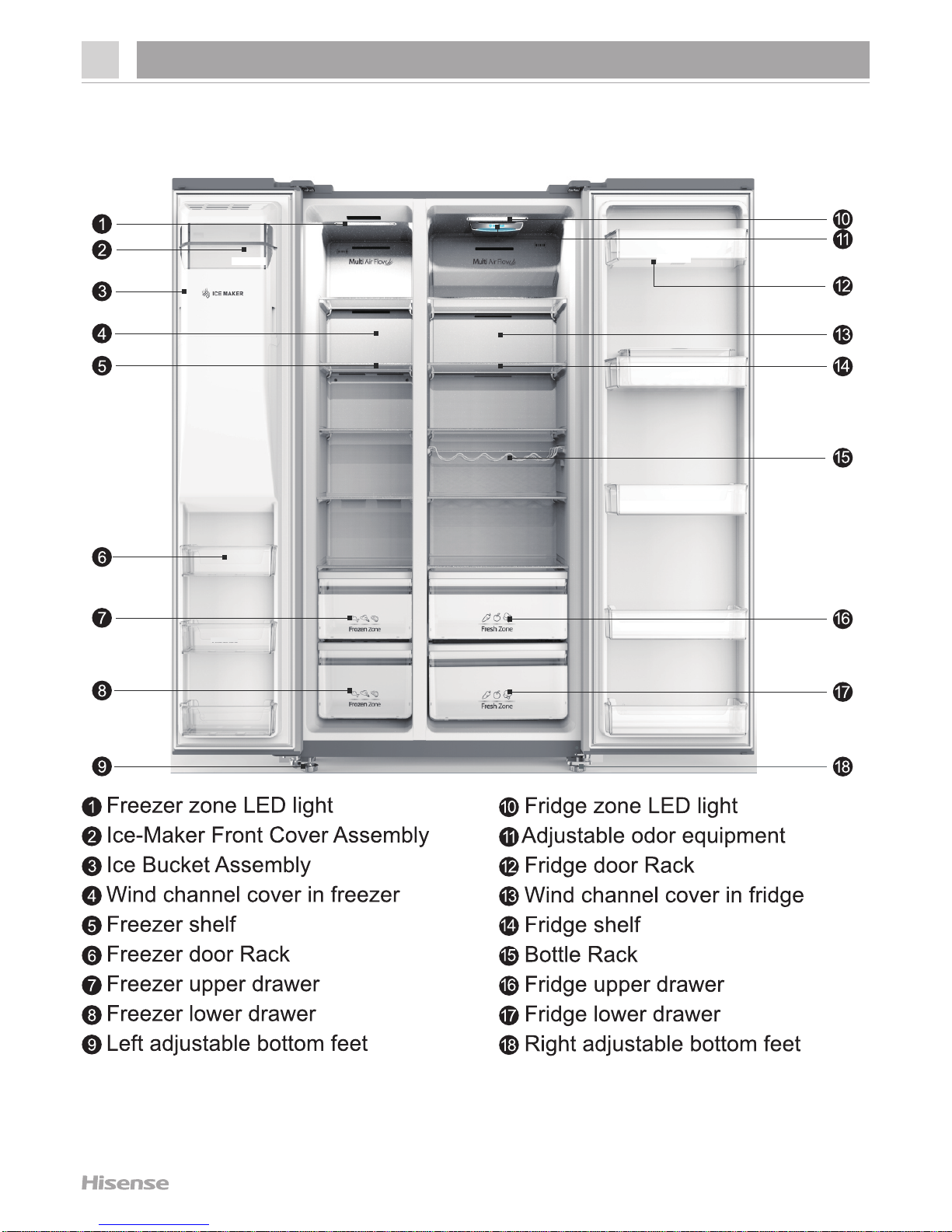
2.Appearance and structure
2 Appearance and structure
Note:Due to unceasing modification of our products,your refrigerator may
be slightly differant from this Services Manual,but its functions and using
methods remain the same.
2.1 View of the appliance
Page 5
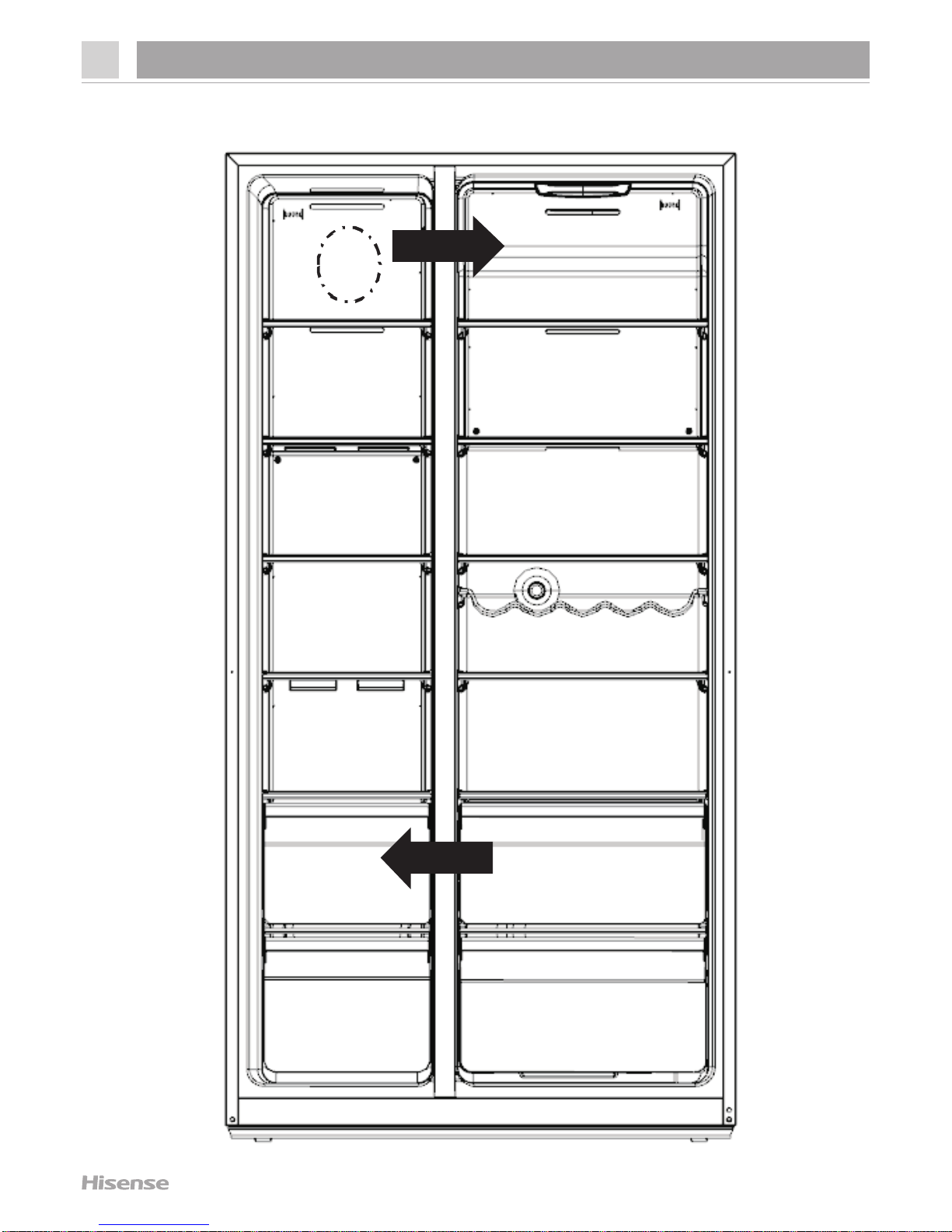
2.2 Wind channel structure
4
2.Appearance and structure
Freezer Refrigerator
Fan
Wind input
Air return
Page 6

2.2 Wind channel structure
5
2.Appearance and structure
Freezer
Fan
Refrigerator
Page 7

2.2 Evaporator structure
6
2.Appearance and structure
Sensor
Evaporator
Fuse
Heater
Accumulator
Capillary
Page 8
7
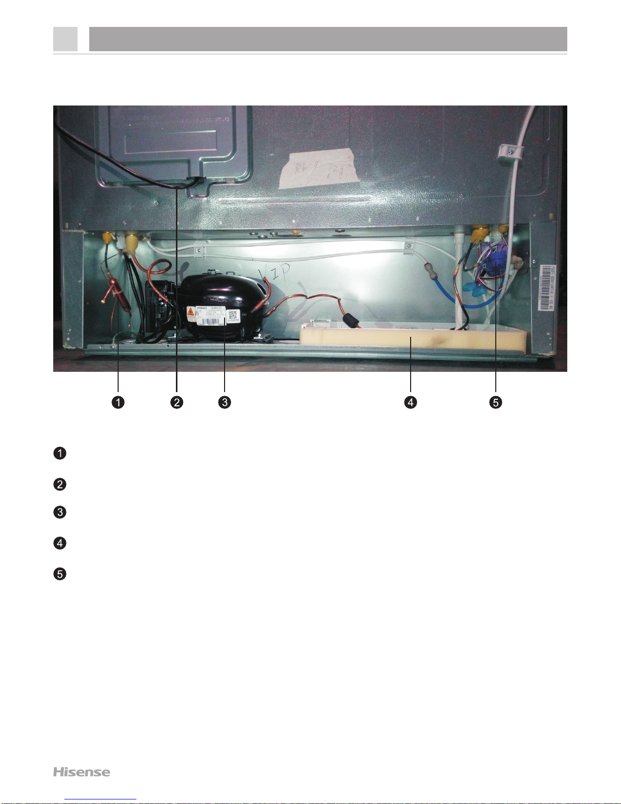
2.2 Compressor room structure
2.Appearance and structure
Dry filter
Power cord
Compressor
Evaporation dish
Water valve
Page 9
8
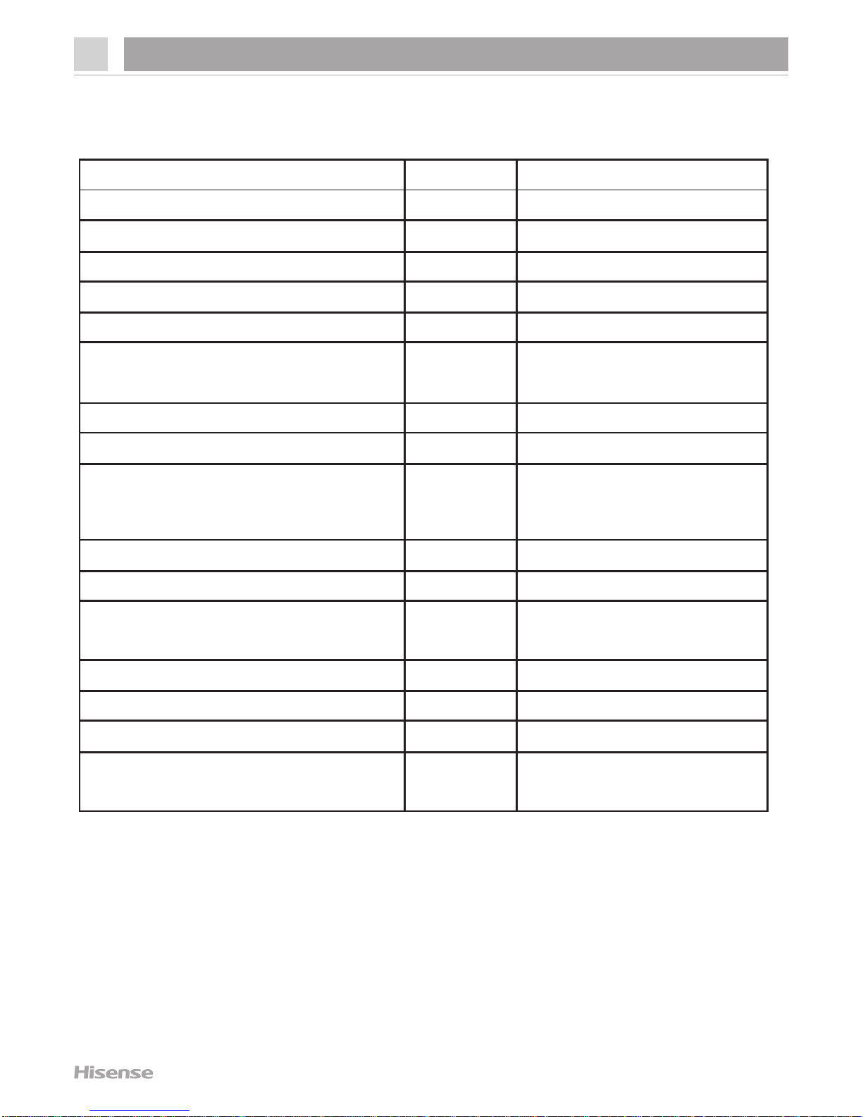
3.Basic parameters
Content
Unit
Value
Voltage / frequency
V/Hz
220-240/50
Rated current A 1.6
Rated input power
W
230
Defrost power W 252
Net capacity
L
535
Net capacity fridge compartmen
(Fridge/Chill)
L
367
Net capacity freezer compartment
L
168
Energy efficiency class
A+
Climate class (SN=10~32°C,
N=16~32°C, ST=16~38°C, T=16~43°C)
SN、N、ST、T
Refigerator room temperature
°C
2~8
Freezer room temperature
°C
-24~-14
Freezer compartment star rating
160L 4 Star
8L 2 Star
Energy consumption / year
kWh/year
438
Freezing capacit y / 24 hours
kg/24 h
13
Max noise level
dB(A)
=42
Kind of coolant / Charge
(R134a/R600a) / grammes
R / g
R600a/72
3 Basic parameters
Page 10
9
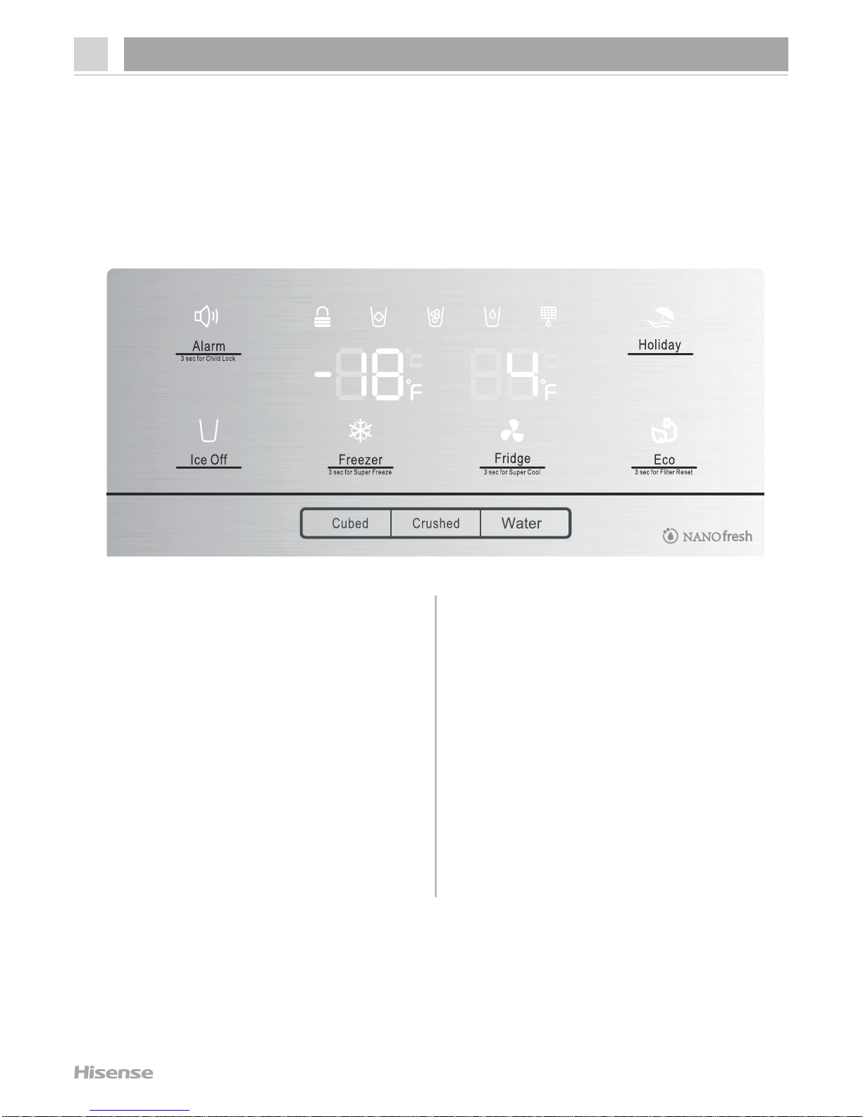
4.Operation and functions
4.1 Display controls
OFF
Use your appliance according to the following control regulations, your
appliance has the corresponding functions and modes as the control panels
showed in the pictures below.
When the appliance in powered on for
the first time, the backlighting of the
icons on display panel starts working.
If no buttons have been touched and
the doors are closed, the backlighting
will turn off after 60 seconds.
Caution! When you set a
temperature, you set an average
temperature for the whole refrigerator
cabinet. Temperatures inside each
compartment may vary from the
temperatures displayed on the panel,
depending on how much food you
store and where you place it. High or
low room temperature may also affect
the actual temperature inside the
appliance.
The control panel consists of two
areas about temperature, one area
about different modes.
4 Operation and functions
Page 11
10
4.Operation and functions
Page 12
4.Operation and functions
11
Page 13

4.Operation and functions
12
Page 14

4.2 Using the appliance
4.Operation and functions
13
Page 15
4.Operation and functions
14
Page 16
4.Operation and functions
15
Page 17
4.Operation and functions
16
207~689
K
Page 18

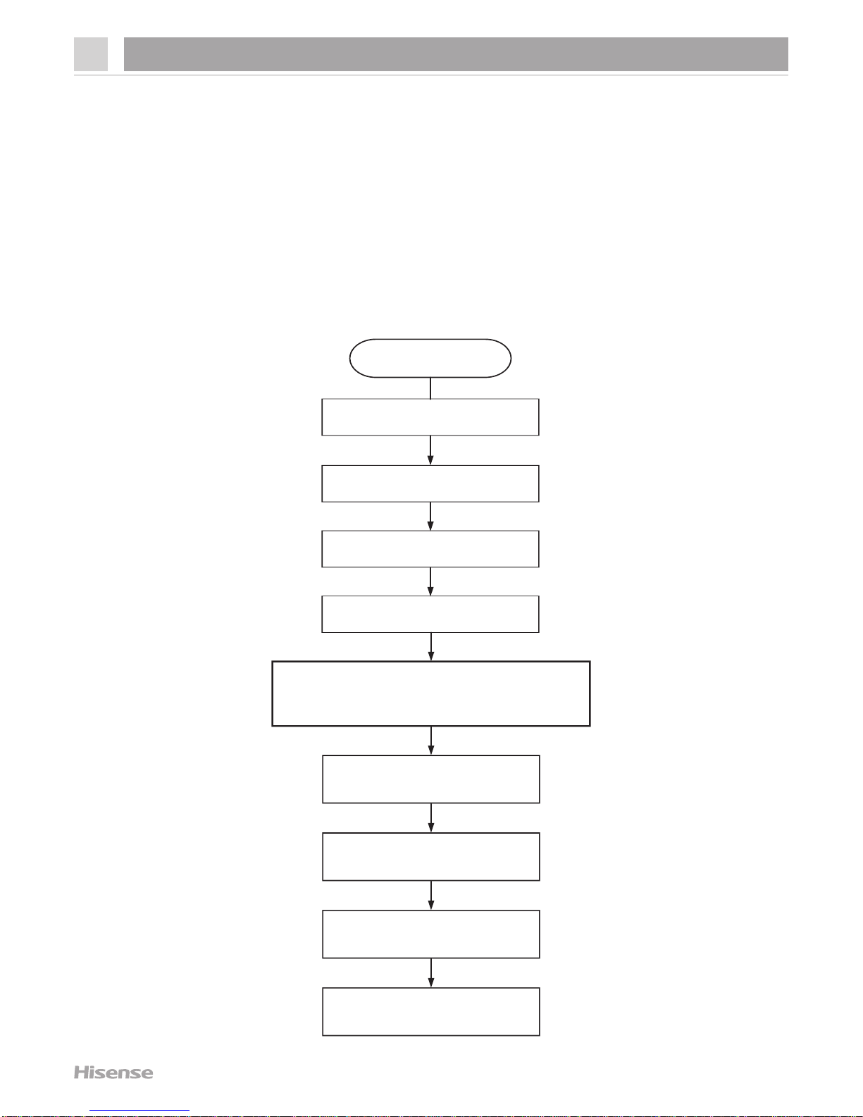
4.3 Defrost mode
4.Operation and functions
4.3.1 Start condition
When compressor accumulated running time reach the setting point
(depends on the environment temperature),it will enter defrost mode
automatically.
4.3.2 Defrost flow
Compressor stops
Evaporator fan stops
Damper stops
Defrost heater works
Evaporator temperature reach the
setting point,exit defrost mode
Defrost heater stops
Compressor starts
several minutes delay
Evaporator fan starts
several minutes delay
Damper starts
Start
17
Page 19
4.4 Compulsory Defrost mode
4.Operation and functions
4.4.1 Start condition
Keep refrigerator door and freezer door closed for 10 minutes after
power-on,touch and hold “Ice off” button and “Freezer” button at the
same time for 5 seconds,it will enter compulsory defrost mode after a
long buzzing sound.
Compressor stops
Evaporator fan stops
Damper stops
Defrost heater works
90 seconds later,
until evaporator temperature
reach the setting point
exit defrost mode
Defrost heater stops
Compressor starts
several minutes delay
Evaporator fan starts
several minutes delay
Damper starts
Start
4.4.2 Compulsory defrost flow
18
Page 20
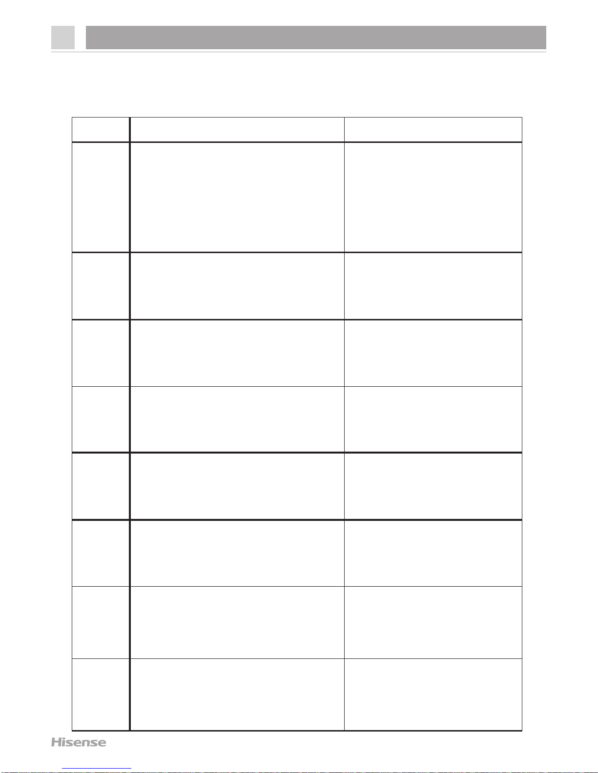
4.5 Error display
4.Operation and functions
4.5.1 Error code
Code Display area problem
E1
Refrigerator temperature
display area
Refrigerator sensor
malfunctions
E3
Freezer temperature
display area
Freezer sensor
malfunctions
E4
Freezer temperature
display area
Defrost sensor
malfunctions
E0
Freezer temperature
display area
Environment sensor
malfunctions
E9
Freezer temperature
display area
Ice maker sensor
malfunctions
Eb
Freezer temperature
display area
Ice maker
malfunctions
Ec
Refrigerator temperature
display area
Communication
sending
malfunctions
Er
Refrigerator temperature
display area
Communication
receiving
malfunctions
19
Page 21
4.5 Error display
4.Operation and functions
4.5.2 Checking method
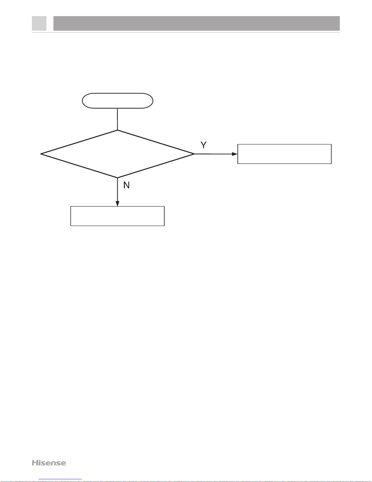
4.5.2.1 Environment sensor error
Start
Change the display
panel
Is the sensor connecting
wiring open circuit
or short circuit?
Repair the wiring
20
Page 22

4.Operation and functions
Start
Change the mainboard
Is the sensor connecting
wiring open circuit
or short circuit?
Repair the wiring
Is the sensor OK?
Change the sensor
Does the sensor connector
plug well?
Plug the terminal well
4.5.2.2 Other sensors error
21
Page 23

4.Operation and functions
4.5.2.2 Other sensors error
Note:
1.Refrigerator sensor corresponding pin No.8 and No.12 on CN5
connector of mainboard.
2.Freezer sensor corresponding pin No.9 and No.12 on CN5
connector of mainboard.
3.Evaporator sensor corresponding pin No.10 and No.12 on CN5
connector of mainboard.
4.Ice maker sensor corresponding pin No.11 and No.12 on CN4
connector of mainboard.
22
Page 24

4.Operation and functions
4.5.2.3 Ice maker error
Eb error:
1.Check the connecting wiring between mainboard and ice maker
(corresponding pin No.7~10 on CN4 connector of mainboard,as the
drawing below) and repair if it is broken.
2.Input 12V power to pin No.7 and No.8 on CN4 connector of
mainboard,check the ice maker can positive rotating(Red wiring
connect power,white wiring connect GND) and negative rotating
(white wiring connect power,red wiring connect GND) normally or not.
If it is abnormal,change the ice maker or mainboard.
23
Page 25

4.Operation and functions
4.5.2.4 Communication error
Note:
The display panel corresponding pin No.5~8 on CN7 connector of the
mainboard,as the drawing below.
Start
Change the mainboard
Is the connecting wiring
between display panel and
mainboard broken?
Repair the wiring
Is the display panel OK?
Change the display
panel
24
Page 26

5.Troubleshooting
5.1 Common problem and checking
Problem Possible cause & Solution
Appliance is not
working correctly
Check whether the power cord is plugged into the power outlet
properly
Check the fuse or circuit of your power su pp ly, replace if necessary
The ambient temperature is too low. Try setting the chamber
It is normal that the freezer is not operating during the automatic
defrost cycle, or for a short time after the appliance
Odours from the
compartments
The interior may need to be cleaned
Some food, containers or wrapping cause o dours
Noise from the
appliance
The sounds below are quite normal:
l Compressor running noises.
l Air movement noise from the small fan motor in the freezer
compartment or other compartme nts.
l Gu rgling sound similar to water boiling.
l Popping noise during automatic defrosting
Other unusual noises are due to the reasons below and may need
you to check and take action:
l The cabinet is not level.
l The back of appliance touches the wall
The motor runs
continuously
l It is normal to frequently hear the sound of the motor, it will
need to run more when in following circumstances:
Temperature setting is set colder than necessary.
l Large quantity of warm food has re cently been stored within
the appliance.
l The temperature outside the appliance is too high.
l Doors are kept open too long or too often.
l After your installing the appliance or it has been switched off
25
Page 27

26
5.Troubleshooting
Problem Possible cause & Solution
A layer of frost
occurs i n the
compartment
Check that the air outlets are not blocked by food and ensure food
is placed within the appliance to allow sufficient ventilation. Ensure
that door is fully closed. To remove the frost,please refer to
cleaning and care chapter.
Temperature inside
is too warm
You may have left the doors open too long or too frequently; or the
doors are kept open by some obstacle; or the appliance is located
with insufficient clearance at the sides,back and top.
Temperature inside
is too cold
Increase the temperature by following the"Display controls"
chapter.
Doors can't be
cloased easily
Check whether the top of the refrigerator is tilted back by 10-15mm
to allow the doors to self close, or if something inside is preventing
the doors from closing.
Water drips on the
floor
he water pan (located at the rear bottom of the cabine t) may not be
properly leveled, or the draining spout underneath the top of the
compressor depot may not be properly positioned to direct water
into this pan, or the water spout is blocked, or the water is not fully
inserted into the connector. You may need to pull the refrigerator
away from the wall to check the pan and spout and connector.
The light is not
working
l The LED light may be damaged. Refer to replace LED lights
in cleaning and care chapter.
l The control system has disabled the lights due to the door
being kept open too long, close and reopens the door to
reactivate the lights.
Ice is not dispensing
l Did you wait for 4 hours after installation of the water supply
line before making ice? if it is not sufficiently cool, it may take
longer to make ice, such as when first installed.
l Is the water line connected and the water valve open?
l Did you manually stop the ice making function? Make sure
you have set the Cubed or Crushed mode on.
l Is there any ice blocked within the ice maker bucket or ice
chute?
l Is the freezer temperature too warm?Try setting the freezer
temperature lower.
Page 28

27
5.Troubleshooting
Problem Poss ible cause & Solution
Water dispenser is not
functioning
l Is the water line connected and the water valve open?
l Has the water line been crushed or kinked? Make
sure the water line is free and clear of any obstruction.
l Is the water tank frozen because the refrigerator
temperature is too low? Try selecting a warmer setting
on the display panel.
l Check if the filter is properly installed.If it is not
properly installed,the water dispenser may not wo rk.
You can hear water
bubbli ng in the
refrigerator
This is normal. The bubbling comes from the refrigerant
coolant liquid circulating through the refrigerator.
Page 29

28
5.2 Faulty start
5.Troubleshooting
Has the power cord plugged
into the power outlet?
Are mainboard terminals
plugged well?
Is the compressor OK?
Plug the power cord
well
Change the
mainboard
Change the
compressor
Start
Is mainboard output
power OK?
Plug the terminals
well
Check connectors
and sensors
Page 30

29
5.3 Refrigeration failure
5.Troubleshooting
5.3.1 Freezer compartment
Any error code?
Does Fan motor
work?
Is fan motor OK?
Change the
fan motor
Is wiring
connection OK?
Change the
mainboard
Freezer door has gap?
Door gasket has gap?
Change the door
gasket
Reassemble the
door
Is the door hanged
down?
Is food palced too close
to the sensor or cold
air spout?
Explain not to place food
too close to sensor or cold
air spout
Start
Refer to “4.5 Error
dispaly” chapter
Does compressor
work?
Check lead wire
Is the compressor
OK?
Change the
compressor
Is the PTC starter
or overload protector
OK?
Check the
mainboard
Change the PTC starter
or overload protector
Page 31

30
5.Troubleshooting
5.3 Refrigeration failure
5.3.1 Freezer compartment
Is Temp. fuse OK?
Change the
Temp. fuse
Is defrost heater
OK?
Is there ice blockage
on evaporator?
Do doors open
frequently?
Explain not to open
doors frequently
Counsel to use colder
temperature setting
Change the
defrost heater
Check ice formation on
Eva. and if refrigerant
leak is found,repair it
Page 32

31
5.Troubleshooting
5.3 Refrigeration failure
5.3.2 Refrigerator compartment
Any error code?
Does the damper work?
Is the damper OK?
Change the
damper
Change the
mainboard
Is the sensor OK?
Is wiring connection
OK?
Change the sensor
and check connector
Is freezer compartment
OK?
Refer to 5.3.1
chapter
Change the door
gasket
Is the door hanged
down?
Reassemble the
door
Explain not to place food
too close to sensor or cold
air spout
Explain not to open doors
too frequently
Is food palced too close
to sensor or cold air
spout?
Do doors open frequently?
Use colder temperature
setting
Start
Solve error
code problems
Check the wiring
Gap between
refrigerator door and
cabinet?
Gap between
gasket and door?
Page 33

32
5.Troubleshooting
Is dew foramed on the
door gasket surface?
Change the door
gasket
Is door hanged
down?
Do doors open
frequently?
Is the appliance too
close to heat
sources?
Is watery or hot food
stored in the cabinet?
Wipe out dew on the
louver surface and run
the refrigerator again
5.4 Thick frost in freezer compartment
Start
Reassemble the
door
Explain not to open
doors too frequently
Make enough distance
between heat sources
and appliance
Gap between
gasket and
cabinet?
Page 34

33
5.Troubleshooting
5.5 Dew in refrigerator compartment
Is dew foramed on the
door gasket surface?
Change the door
gasket
Is the door
hanged down?
Does the door open too
frequently?
Is the appliance too
close to heat sources?
Is watery or hot food
stored in the cabinet?
Advise to cool down hot
food and seal watery
food well before storing
Make enough distance
between the appliance
and heat sources
Explain not to open
doors too frequently
Start
Gap between
gasket and
cabinet?
Reassemble the
door
Page 35

34
5.Troubleshooting
5.6 Low temperature of vegetable vase
Is the damper OK?
Change the damper
Is the sensor OK?
Change the sensor
Check the sensor
connection and repair
Counsel to use warmer
temperature setting
Start
Is refrigerator temperature
setting too cold?
Is the mainboard
output power OK?
Check the mainboard
Page 36

35
5.Troubleshooting
5.7 Breaking of light
Is the light disconnected
or broken?
Is the door switch OK?
Change the door switch
Check the door switch
connection and repair
Start
Change the light
Page 37

36
5.8 Noise
5.Troubleshooting
5.8.1 Compressor noise
Is the appliance leveled?
Level the appliance by
adjusting the bottom feet
Are the adjustable bottom
feet broken?
Change the adjustable
bottom feet
Is the noise from compressor
itself?
Add a rubber absorber to
reduce the vibration
Start
Change the compressor
Page 38

37
5.8 Noise
5.Troubleshooting
5.8.2 Refrigerator flowing noise
Is there hiss or sizzling sound
from refrigerant when comp.
starts/stops?
Is there sound from freezer
compartment when compressor ’s
running?
Fasten the evaporator
Start
Is there water flowing or hiss
sound from the appliance?
Attache a gum absorber
on the capillary tube
Attach a gum absorber
on the accumulator
Explain to customer that
it is normal sound of
the running appliance
Page 39

38
5.8 Noise
5.Troubleshooting
5.8.3 Fan motor noise
Fasten the fan motor
Sound from fan itself or
vibration when working?
Change the fan motor
Is the fan damaged
or transformed?
Is the fan touching
surround?
Set the fan right,avoid to
touch surround
Start
Is the fan moving
or shaking?
Change the fan
Explain to the customer
that it is normal sound of
the running appliance
Page 40

39
5.8 Noise
5.Troubleshooting
5.8.4 Pipe noise
Does evaporation dish make
noise by touching the
pipe?
Check the cushion between
pipe and evaporation
dish and repair
Is pipe itself shaking strongly?
Is compressor itself shaking
strongly?
Are pipes touching in the
compressor room?
Separate the touching
pipes
Attach a gum absorber
on top of the compressor
Start
Move or change the points
of vibration absorber on
pipes to reduce shaking
Explain to the customer
that it is normal sound of
the running compressor
Page 41

40
6.Circuit and checking
6.1 Circuit diagram
Page 42

41
6.2 Mainboard
6.Circuit and checking
6.2.2 Removing the mainboard
1.Unplug the appliance
2.Remove the screws of electric box cover by screwdriver,as
picture 1.
3.Remove the electric box cover,as picture 2.
4.Unplug the terminals on the mainboard,as picture 3.
5.Pry up the mainboard by fingers and take it out,as picture 4.
Picture1 Picture2
Picture3 Picture4
If the problem is probably caused by the mainboard,change it directly
to confirm.
6.2.1 Checking method
Page 43

42
6.3 Compressor
Input voltage/frequency:220-240V/50Hz
Imput power:≤64.2*115% W
6.3.1 Basic parameters
6.3.2 Checking method
6.Circuit and checking
1.Compressor will start 10 seconds after power-on,if it starts
unsuccessfully,remove the electric box cover and check.
2.Check the connecting wiring between compressor and mainboard
and repair if it is broken.
3.Use a multimeter to measure voltage between N label and COMP
label on CN2 connector of mainboard,then measure frequency of CN8
connector.If the voltage equal to electric supply power and there is
stabilized frequency,it means the compressor is broken,change it;
If not,change the mainboard.
Page 44

6.3.3 Removing the PTC starter and overload protector
1.Unplug the appliance
2.Remove the screws of protector box by screwdriver,as picture 1.
3.Pry up the protector box from top by screwdriver,as picture 2.
4.Unplug the overload protector,as picture 3.
5.Unplug the PTC starter,as picture 4.
Picture1 Picture2
Picture3 Picture4
43
6.Circuit and checking
Page 45

44
6.4 Fan motor
Rated voltage:DC12V
Rated input power:2.5W
6.4.1 Basic parameters
6.4.2 Checking method
6.Circuit and checking
1.Check the connecting wiring of fan motor is well or not,repair if it
is broken.The fan motor corresponding pin No.13~15 on CN4
connector of mainboard,as the drawing below.
2.Pin No.14 connect 12V power and pin No.13 connect GND,if the
fan motor works normally,change the mainboard;If not,change the
fan motor.
Page 46

45
6.4.3 Removing the fan motor
6.Circuit and checking
1.Unplug the appliance
2.Remove the screws of freezer wind channel component by
screwdriver,as picture 1.
3.Remove the wind channel component and unplug the terminals,as
picture 2.
4.Remove the screw of the wind channel component by screwdriver,
as picture 3.
5.Pry up the wind channel cover from the buckles by screwdriver,as
picture 4.
6.Separate the front cover and back cover,as picture 5.
7.Remove the screws of fan motor and then remove the fan motor,
as picture 6.
Picture1 Picture2 Picture3
Picture4 Picture5 Picture6
Page 47

46
6.5 Damper
Rated voltage:DC12V
Rated current:60mA
6.5.1 Basic parameters
6.5.2 Checking method
6.Circuit and checking
1.Check the connecting wiring of the damper is well or not,repair if it is
broken.The damper corresponding pin No.1~6 on CN6 connector of
mainboard,as the drawing below.
2.The damper will turn on and off for one time after power-on,if not,
change the mainboard first and change the damper if problem
remains.
Page 48

47
6.5.3 Removing the damper
6.Circuit and checking
1.Unplug the appliance
2.Remove the screws of refrigerator wind channel component by
screwdriver,as picture 1.
3.Remove the wind channel component and unplug the terminals,as
picture 2.
4.Separate the wind channel cover and foam,as picture 3.
5.Remove the sponge and adhesive paper on the foam,as picture 4.
6.Separate the upper foam and lower foam,as picture5.
7.Remove the damper,as picture 6.
Picture1 Picture2 Picture3
Picture4 Picture5 Picture6
Page 49

48
6.6 Light
6.6.1 Basic parameters
1.Check the connecting wiring between light and mainboard is well
or not,repair if it is broken.Refrigerator light corresponding pin No.1
and No.2 on CN7 connector of mainboard,freezer light corresponding
pin No.1 and No.3,ice maker light corresponding pin No.1 and No.4,
as the drawing below.
2.Check output voltage corresponding light of the mainboard,if it is
12V,it means the mainboard is OK,change the light;If not,it means
the mainboard is not OK,change it.
6.6.2 Checking method
6.Circuit and checking
Rated voltage:DC12V
Rated power:2W
Page 50

49
6.6.3 Removing the light
6.Circuit and checking
1.Unplug the appliance
2.Pry up the light cover from the buckles by screwdriver,as picture 1.
3.Remove the light cover,as picture 2.
4.Pry up the light from the buckles by screwdriver,as picture 3.
5.Unplug the terminal of the light,as picture 4.
Picture1 Picture2
Picture3 Picture4
Page 51

50
6.7 Door switch
Load voltage:DC24V
Load current:0.05A
6.7.1 Basic parameters
1.Check the connecting wiring of door switch is well or not,repair if it
is broken.Refrigerator door switch corresponding pin No.4 and No.6
on CN4 connector of mainboard,freezer door switch corresponding
pin No.4 and No.7,as the drawing below.
2.Check the magnet on the door is dropped out or not.
3.Normally,when the door is closed,the two pins of door switch should
be short circuit;When the door is open,the two pins should be open
circuit.If the result is not abnormal,change the door switch.
4.If all above is OK,change the mainboard.
6.7.3 Checking method
6.Circuit and checking
Page 52

51
6.8 Temperature fuse
Max fusing-off temperature:72℃
Load voltage:250V
Load current:10A
6.8.1 Basic parameters
6.8.2 Checking method
6.Circuit and checking
Use a multimeter to measure resistance between the two terminals of
the fuse,if it is open circuit,change the fuse.
Page 53

52
6.8.3 Removing the temperature fuse
6.Circuit and checking
1.After removing the freezer wind channel component,unplug the
terminals,as picture 1.
2.Remove the screws of evaporator by screwdriver,as picture 2.
3.Separate the evaporator component from the cabinet and remove
the foams at left side and right side,as picture 3.
4.Cut the self locking ties that fastening the temperature fuses by
knife and then remove the fuses,as picture 4.
Picture1 Picture2
Picture3 Picture4
Page 54

53
6.9 Defrost heater
Rated voltage:AC220V
Rated power:220W
6.9.1 Basic parameters
6.Circuit and checking
6.9.2 Checking method
1.Enter compulsory defrost mode,use a multimeter to measure
the voltage between pin No.1 and No.9 on XP7 connector of the
mainboard,if the voltage doesn’t equal to electric supply power,it
means the heater is broken,change it.
2.Check the fuse is well or not,refer to “6.8 Temperature fuse”chapter.
3.Use a multimeter to measure resistance of the heater,if the value
isn’t 220Ω±5 % , it is broken,change the heater.
Page 55

54
6.9.3 Removing the defrost heater
6.Circuit and checking
Picture1 Picture2 Picture3
Picture4 Picture5
1.After removing the freezer wind channel component,unplug the
terminals,as picture 1.
2.Remove the screws of evaporator by screwdriver,as picture 2.
3.Separate the evaporator component from the cabinet and remove
the foams at left side and right side,as picture 3.
4.Cut the self locking ties that fastening the heater by knife,as
picture 4.
5.Pry up the buckles that fastening the heater by screwdriver and
then remove the heater,as picture 5.
Page 56

55
6.10 Ice maker
6.9.1 Checking method
6.Circuit and checking
Refer to “4.5 Error display”chapter.
6.9.2 Removing the ice maker
6.9.2.1 Removing the ice bucket
1.Raise the ice bucket up,as picture 1.
2.Pull the ice bucket slantingly downwards,as picture 2.
3.Pull the ice bucket out,as picture 3.
Picture1 Picture2
Picture3
Page 57

Picture1 Picture2
Picture3
6.9.2.2 Removing the water intake
56
6.Circuit and checking
1.Pull the front cover out slantingly upwards,as picture 1.
2.Pull the water intake slantingly upwards,as picture 2.
3.Remove the two buckles of the water intake,as picture 3.
4.Take out the water intake,as picture 4.
Page 58

6.9.2.3 Removing the ice maker and holder
57
6.Circuit and checking
1.Remove the screws of the ice maker holder by screwdriver,as
picture 1.
2.Unplug the terminal of the ice maker,as picture 2.
3.Remove the screws of the ice maker by screwdriver,as picture 3.
4.Remove the wiring,as picture 4.
5.Pull the ice maker upwards and remove it,as picture 5.
Picture1 Picture2 Picture3
Picture4 Picture5
Page 59

6.9.2.4 Removing the ice crushing motor
58
6.Circuit and checking
1.Remove the screws of the motor by screwdriver,as picture 1.
2.Remove the coupling,as picture 2.
3.Remove the screws of the motor cover by screwdriver,as picture 3.
4.Remove the cover and pull out the motor and remove it,as pictire 4.
Picture1 Picture2
Picture3 Picture4
Page 60

6.9.2.4 Removing the ice dispenser
59
6.Circuit and checking
1.Pull out the water tube,as picture 1.
2.Unplug connecting terminal,as picture 2.
3.Remove the screws by screwdriver,as picture 3.
4.Pry up the ice dispenser at the buckles,as pictire 4.
5.Pull out the ice dispenser,as picture 5.
6.Unplug the motor terminal and remove the ice dispenser,as
picture6.
Picture1 Picture2 Picture3
Picture4 Picture5 Picture6
Page 61

6.9.2.4 Removing the water valve
60
6.Circuit and checking
1.Remove the screws of the water valve by screwdriver,as picture 1.
2.Pull out the water valve,as picture 2.
3.Unplug the connecting terminal,as picture 3.
4.Remove the water tube connector,as pictire 4.
5.Remove the water tube,as picture 5.
6.Pull out the water valve,as picture6.
Picture1 Picture2 Picture3
Picture4 Picture5 Picture6
Page 62

61
7.Refrigeration system repair
7.1 Refrigeration system
The refrigerator system is single cycle wind cooling system:
Compressor discharges high temperature
high pressure R600a gas refrigerant
Refrigerant enters evaporation pipe,condenser
and anti-condensation pipe one after another,
then becomes middle temperature high pressure
liquid after condensation
Refrigerant enters dry filter,water and imperity will
be filtrated
Refrigerant enters capillary and pressure will
be reduced
Refrigearnt enters finned evaporator and
become low temperature low pressure gas after
absorbing heat from freezer and refrigerator
compartment
Refrigerant goes back to compressor through
air return pipe and becomes high temperature high
pressure liquid after compressing
Page 63

62
7.Refrigeration system repair
7.1 Refrigeration system
Anti-condensation
pipe
Condenser
Finned evaporator
Compressor
Dry filter
Evaporation pipe
Air return
pipe
Condenser
Page 64

63
7.Refrigeration system repair
7.2 Summary of repair
Page 65

64
7.3 Regualation for repair
7.Refrigeration system repair
Page 66

65
7.4 Practical work for repair
7.Refrigeration system repair
Page 67

66
7.4 Practical work for repair
7.Refrigeration system repair
Page 68

67
7.5 Brazing reference drawing
7.Refrigeration system repair
Anti-condensation pipe
Condenser
Capillary
Air return pipe
Dry filter
Connecting pipe
Connecting pipe
Compressor
Finned
evaporator
Evaporation
pipe
Refrigearnt flowing direction
Welding points
 Loading...