

Page 1
Refrigerator
Service manual
NO FROST
Model: RS-47WL* BC-355WY
NOTE: product specifications are subject t o change.
Page 2

1
Contents
Warnings and precautions for safety ............................................................................................................................ 2
Parts Description .......................................................................................................................................................... 3
Circuit diagram basic features ..................................................................................................................................... 4
Cooling diagram .......................................................................................................................................................... 5
Display controls ........................................................................................................................................................... 6
Filling the water tank ................................................................................................................................................... 7
Receiving water from the water dispenser ................................................................................................................... 8
Checking the Compressor ............................................................................................................................................ 8
Checking the defrost fuse .......................................................................................................................................... 10
Checking the Heater .................................................................................................................................................. 10
The guide for Disassembly Common parts of Refrigerator………………………………………………………...11
◆The instruction of replacing the main board and display board. ............................................................................. 11
◆The instruction of of replacing fan motor ............................................................................................................... 11
◆The instruction of replacing temperature sensor. ................................................................................................... 12
◆The instruction of replacing evaporator temperature sensor and temperature fuse and heater .............................. 13
◆The instruction of replacing PTC Starting relay and Overload protector. ............................................................. 13
◆The instruction of replacing Door switch. ............................................................................................................. 14
◆The instruction of replacing Display board. .......................................................................................................... 14
◆The instruction of of replacing lamp. ..................................................................................................................... 15
Installing your new appliance .................................................................................................................................... 16
Troubleshooting ......................................................................................................................................................... 20
◆ The solution for digital display code problem ..................................................................................................... 20
◆ The common problem judgement method ........................................................................................................... 20
◆ The solution for the common problem................................................................................................................. 22
■ NOTE: ............................................................................................................................................................... 24
Page 3

2
Warnings and precautions for safety
Please observe the following safety precautions in order to use safely and correctly the refrigerator
and to prevent accident and danger during repair.
1. Be care of an electric shock. Disconnect power cord from wall outlet and wait for more than
three minutes before replacing PCB parts.
Shut off the power whenever replacing and repairing electric components.
2. When connecting power cord, please wait for more than five minutes after power cord was
disconnected from the wall outlet.
3. Please check if the power plug is pressed down by the refrigerator against the wall.
If the power plug was damaged, it may cause fire or electric shock.
4. If the wall outlet is over loaded, it may cause fire.
Please use its own individual electrical outlet for the refrigerator.
5. Please make sure the outlet is properly earthed, particularly in wet or damp area.
6. Use standard electrical components when replacing them.
7. Make sure the hook is correctly engaged.
Remove dust and foreign materials from the housing and connecting parts.
8. Do not fray, damage, machine, heavily bend, pull out or twist the power cord.
9. Please check the evidence of moisture intrusion in the electrical components.
Replace the parts or mask it with insulation tapes if moisture intrusion was confirmed.
10. Do not touch the icemaker with hands or tools to confirm the operation of geared motor.
11. Do not let the customers repair, disassemble and reconstruct the refrigerator for themselves.
It may cause accident, electric shock, or fire.
12. Do not store flammable materials such as ether, benzene, alcohol, chemicals, gas, or
medicine in the refrigerator.
13. Do not put flower vase, cup, cosmetics, chemicals, etc., or container with full of water
on the top of the refrigerator.
14. Do not put glass bottles with full of water into the freezer.
The contents shall freeze and break the glass bottles.
15. When you scrap the refrigerator, please disconnect the door gasket first and scrap it
Page 4
3
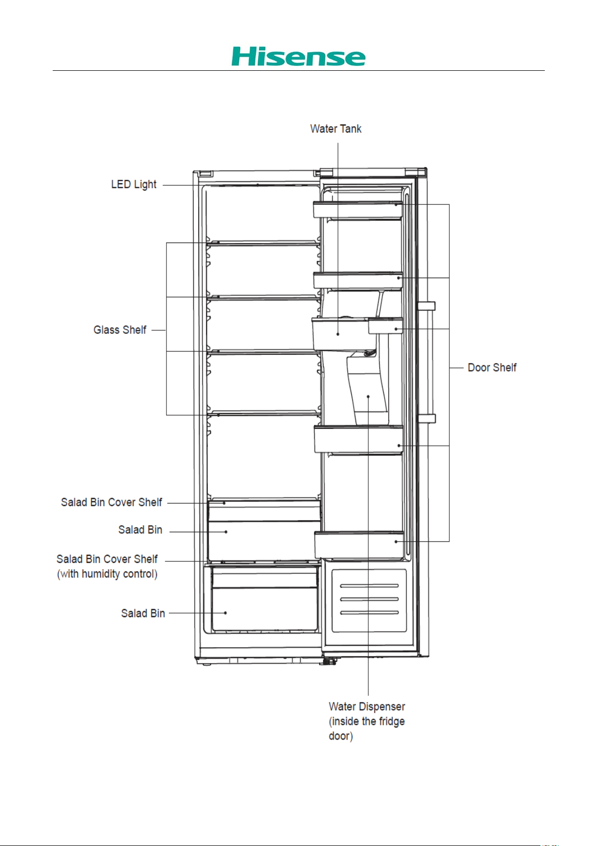
Parts Description
Page 5
4
V/Hz
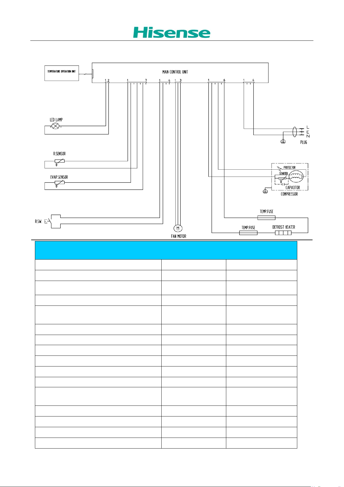
Circuit diagram basic features
Basic features
Voltage / frequency (
Net capacity l RC-72W
Net capacity fridge compartmen (Fridge/Chill) l 355L
Energy efficiency class
Climate class (SN=10~32°C, N=16~32°C,
ST=16~38°C, T=16~43°C) SN、N、ST、T
Freezer compartment star rating 4 Star
Energy consumption / year kWh/year 165
Energy consumption (ISIRI 4853-2) per 24 h kWh/24 h 0.452
Compressor (W) 220V,165W
PTC starter (V/Ω) 220V ,15±20%Ω
Overload protector (Turn off/Turn on) °C 120±5°C/ 61±9°C
Heater (V/W/Ω)
) 220-240V~ 50HZ
A+
220V,120W±10%
403Ω±10%
LED Light (V/W) 12V,1W
fan motor (V/W) 13V,2W
Max noise level dB(A) ≤40
Kind of coolant / Charge (R134a/R600a) / R / g R600a/46
Page 6
5
grammes
Net weight kg 69
Gross weight kg 77
W x D x H (appearance) mm 595×712×1855
W x D x H (packaging) mm 643×713×1945
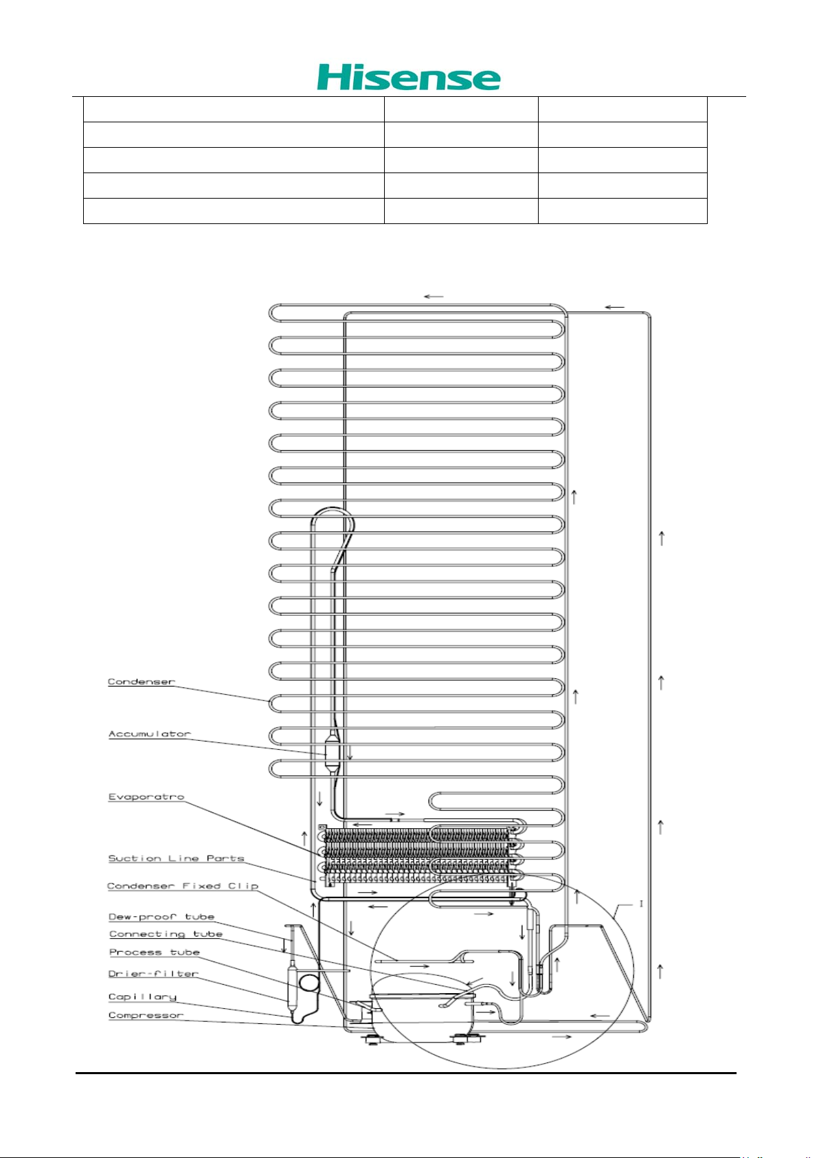
Cooling diagram
Page 7
6
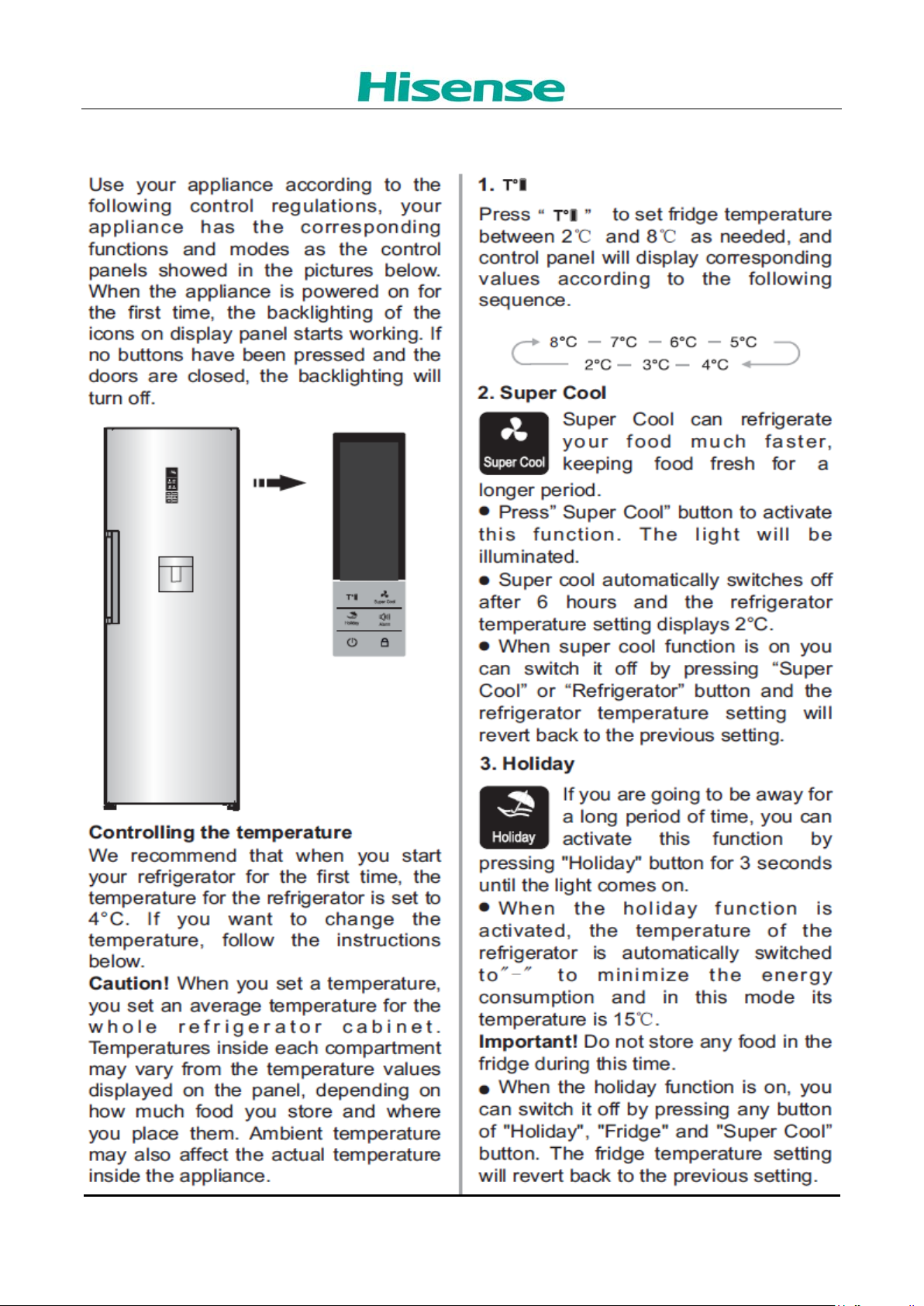
Display controls
Page 8
7
Filling the water tank
Turn the small cap anticlockwise then remove it from the water tank. Fill drinking water into the
water tank through the hole.
Page 9

8
• Do not fill above the level, otherwise, it may overflow.
• Before filling with water, ensure that the water tank is steady and in a correct position.
• Apart from drinking water, other beverages (such as milk, juice, carbonated beverage, etc)
are not suggested to be used, especially beverages that include grain must not be used
(may result in blockage and damage).
• Hot water must not be filled into the water tank directly.
• Do not touch other parts of the unit when filling water, it may lead to leakage.
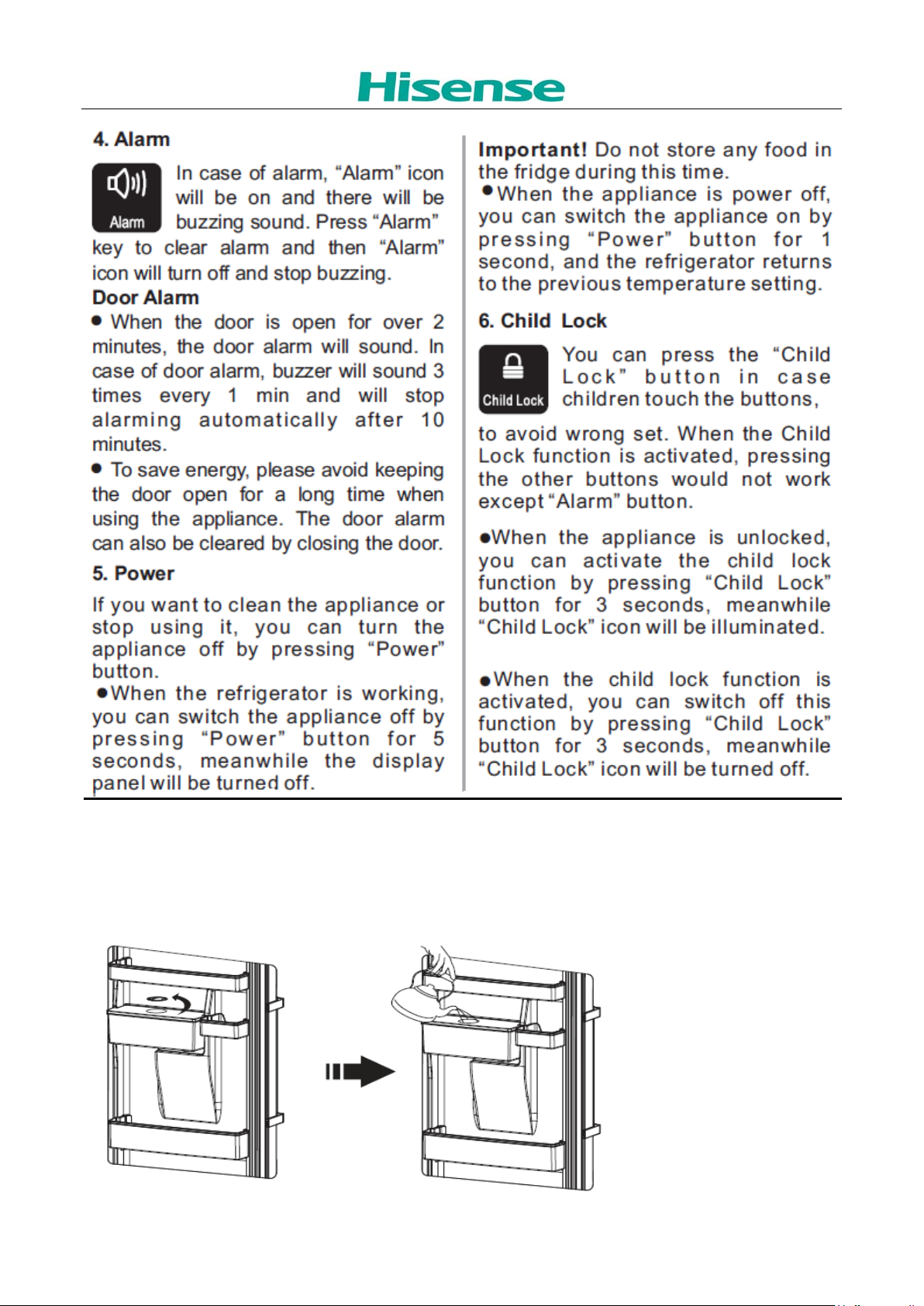
Receiving water from the water dispenser
• You should use the type of container that can fit
under the water dispenser. Place the container
properly underneath and push on the lever for water to flow.
• Before you dispense the water, make sure the lock device is at “Unlock” position.
Ensure to slide to “Lock” position after each use to prevent children from playing with the lever.
• When at “Lock” position, do not push on the lever with force. It will damage the mechanism.
Checking the Compressor
Use a multi-meter to test the resist ance between C & M, C&S and S&M :
Normal range of C&M : About 10-21Ω
Page 10

9
Normal range of C&S : About 10-27Ω
Normal range of S&M : About 20-50Ω
If the test result is not in this range then it means the inner coil has some problem and the compressor
can not work properly.
Compressor Protector tes t ——
Use a multi-meter to test the resistance betwee n t he two end as the pic show :
If there show 000 or almost 0 t hen it is OK.
If there is no response then it is broken.
Compressor PTC star t er t est ——
Use a multi-meter to test the resist ance between the two end as t he pic show :
If there show the number is betw een About 9-25Ω then it is OK.
If there show 000 or no respons e t hen it i s br oken.
Page 11

10
Checking the defrost fuse
Fuse is a high temperatur e protect or o f defro st s yst em, wh en de fros ting, if it f eel the te mper atur e is mor e
than 73℃, it will cut off the defrost heater, stopping defrost, so that it can protect the parts. The common
problems are evaporator defrost incomplete:
Checking method as following:
Picture 1 Picture 2
As picture 1,it is the defrost fus e.
As picture 2 , using the multimet er m easure two foots of fuse, i f the value of resistance is 0000, it m eans
normal.
Checking the Heater
If defrost system failure,checking the heater and the temperatur e fuse as well as wires.
Measuring temperature fuse and heater resist ance about 403Ω then it is OK.( Brown and Blue)
Page 12

11
The guide for Disassembly Common parts of Refrigerator
◆The instruction of replacing the main board and display board.
Unscrew the back
cover screws
Remove the electron
box cover and rep lace
the main board.
◆The instruction of of replacing fan motor
Page 13

12
Remove the wind
channel plate in
freezer chamber.
Remove the air duct
Board
Open air duct Board
Unscrew the fan
motor screws
And take out fan motor
◆The instruction of replacing temperature sensor.
Page 14

13
Open air duct Board
And take out sensor
◆The instruction of replacing evaporator temperature sensor and
temperature fuse and heater
1.Take out the
temperature fuse
2. Take out the defrost
sensor
3. Take out the heater
◆The instruction of replacing PTC Starting relay and Overload protector.
Page 15

14
1. The location of the
PTC Starting relay and
Overload protector.
2. Disconnect the
connect ing wire of the
PTC Starting relay and
Overload protector.
◆The instruction of replacing Door switch.
Using a screwdriver to
pry the upper cover
plate
And take out switch
◆The instruction of replacing Display board.
1. The location of the
display board .
Page 16

15
2. Unplug the display
board wires and
remove the screws
fixing .
◆The instruction of of replacing la mp .
1. The location of the
lamp.
2. Unplug the electrical
wires and remove the
screws fixing the lamp
board.
Page 17

16
Installing your new appliance
Page 18

17
Page 19

18
Page 20

19
Page 21

20
switch to measure the resistor of
1. The Evaporator Defrost
The Evaporator Defrost
switch to measure the resistor of
fault between the main
The freezer digital display
Troubleshooting
◆ The solution for digital di sp lay code problem
1. The Refrigerator chamber
Tem. Sensor is open circuit or
The digital display window
1
show “E1”
The digital display window
2
show “E2”
3
4
The testing method of sensor:
Using the mult imeter with the ohm switch to measure the resistor of sensor, normally at surrounding 25℃ the
resistor should be about 2kohm and every with the temperature decreases 1℃ the corresponding resistor value
would increase about 45ohm.If the measured value is not within the normal scope, the sensor is bad and needs
to repair or change.
The digital display window
show “EC”
window show “EF”
short circuit.
2. The Refrigerator chamber
Tem. Sensor is bad.
3. The control PCB is bad.
Sensor is open circuit or short
circuit.
2.
Sensor is bad.
3. The control PCB is bad.
1. The receive communicat ion
electrical PCB and the display
PCB.
2. The control PCB is bad.
3. The display PCB is bad.
1. The Fan motor is open
circuit or short circuit.
2. The Fan motor is bad.
3. The control PCB is bad.
1. Using a Mult imeter with the ohm
sensor or checking the connecting is
well or not.
2. Change the sensor
3. Change the control PCB
1. Using a Multimeter with the ohm
sensor or checking the connect ing is
well or not.
2. Change the sensor
3. Change the control PCB
1. Check the wire terminal is well or
not between the main electrical PCB
and display PCB.
2. Change the main electrical PCB.
3. Change the display PCB.
1. Using a Mult imeter with the ohm
switch to measure the resistor of Fan
motor or checking the connect ing is
well or not.
2. Change the Fan motor
3. Change the control PCB
◆ The common problem judgement method
Problem Cause
Refrigerator can’t start
1.1 Is the power cord connect ing well?
1.2 Is the power voltage too low?
1.3 Is the sensor irrational sett ing?
1.4 Is the ambient temperature too low?
1.5 Is the circuit on power?
1.6 Is there some default in compressor
1.7 Is the refrigerat ion system blocked by ice or dirty, please stop the unit and restart
Page 22

21
Weak cooling effects
n, specially the thermostat wich will cause the
dissolving
The unit can not stop
running
Ice up in the freezing
chamber
Abnormal noise
There is a peculiar
smell in the units
the forefront or the
middle cabinet heats
Refrigerator’s two
sides or the back heat
the cabinet surface
condensat ion
after 10 minutes to see if the compressor can start.
2.1 Is there any heat source around the refrigerator?
2.2 Is there enough space around the refrigerator for rejection of heat?
2.3 Is the setting of the temperature appropriate?
2.4 Is there too much food or overheat ing food in it?
2.5 Does there open the door frequently?
2.6 Is the door completely closed?
2.7 Does the gasket destroyed or distort?
2.8 Does the gas leak?
3.1 Is there any heat source around the refrigerator?
3.2 Is there enough space around the refrigerator for rejection of heat?
3.3 Is the setting of the temperature appropriate?
3.4 Is there too much food or overheat ing food in it?
3.5 Does there open the door frequently?
3.6 Is the door completely closed?
3.7 Does the gasket destroyed or distort?
3.8 Is the thermostat good operation?
3.9 Does the gas leak?
4.1 Is the sett ing of the temperature appropriate?
4.2 Is there multi-moisture food and too close to the back wall of the refrigerator?
4.3 Is the ambient temperature too low?
4.4 Is the electric parts on good condit io
unit non-stopping .
5.1 Is the refrigerator stably placed?
5.2 Does the refrigerator bump other objects?
5.3 Whether the internal accessory of the refrigerator is in the right place.
5.4 Whether the water plate of compressor is fall from the unit.
5.5 Does the tube of the refrigeration system bump each other?
5.6 The noise sound likes Water flow inside the refrigerator ,in fact ,it is normal, which is
caused both when refrigerator start and shut-down; in addition, frost-
causes this sound, too, which is a normal phenomenon.
5.7 There will be a cracking sound in the cabinet ,when the cabinet or cabinet accessory
contract ing or expanding, this sound will be made, which is normal.
5.8 The motor operat ion sound in the compressor is appears to be louder at night or
begin start ing. which is a normal phenomenon; also the uneven placing would lead to
too much running noise.
6.1 Is the food with special smell sealed tight?
6.2 Does it have long time storing food or degenerated food?
6.3 Whether the internal cabinet needs cleaning.
7.1 As fridge Anti-condensat ion tube is placed here and caused the above phenomenon,
which is normal.
8.1 As condensat ion tube is placed here and caused the above phenomenon, which is
normal.
9.1 Air humidity is too large.
Page 23

22
◆ The solution for the common problem.
and then open charging tube,
and then open charging tube,
1.Cooling is not enough good
(Many reasons might cause that cooling not enough good, as blow :)
Reason analysis Solutions
1) Leakage of Gas
2) The quant ity of Gas is
too much
3) There is air in the
liquid cycle system
4)Low working
efficiency of
compressor
If some gas leaked unit will work not well.
Phenomenon of failure:
a. lower pressure of liquid cycle system
b. high temperature of copper tube of
discharging gas, hand feels very hot.
C. much noise, sounds like “ZZZZZ”, comes
from outlet of capillary.
d. the temperature fell down very slowly.
If too much Gas was charged into the cycle
system, the extra gas will occupy some space
of evaporator, so that the area of heat
exchange becomes less, unit will work not well.
Phenomenon of failure:
a, higher pressure of liquid cycle system than
norm.
b, higher temperature of condenser.
c, larger electric current of compressor
d, there maybe ice on the suction tube.
e, when gas is too much, some gas liquid might
goes back into compressor, compressor will be
damaged by liquid.
The air in system will cause lower efficiency of
cooling.
Phenomenon of failure:
a, higher pressure of liquid cycle system than
norm, but the pressure is not over the limit.
b, higher temperature of discharging tube.
C, much noise
General when a compressor works for many
years, some parts of compressor were wear, so
that compressor discharge less gas out, unit
does not work strongly.
Phenomenon of failure:
a, lower pressure of discharging, check the
pressure of system with pressure meter to see
if it is normal.
b, higher temperature of compressor surface.
C, cut off the discharging tube, to see if you can
block the gas coming out of the tube when
compressor is working.
First find out the point of leaking on
tube, and then sealed it, vacuuming
it, finally recharge with Gas.
Note:
If you find oil on somewhere, it is
possible that leakage point is there.
First stop unit for several minutes,
discharge all of gas. Change a new
filter, and then recharge gas, f inally
sealed the system.
First stop unit for several minutes,
discharge all of gas. Change a new
filter, and then recharge gas, f inally
sealed the system.
Change a new compressor.
Page 24

23
Some t ime there is something blocked the
5) There is something
that blocked the liquid
cycle system
filter of liquid cycle system, so that unit is not
cold.
Phenomenon of failure:
a, lower pressure of discharging
b, lower temperature of discharging.
2.NO COOL
(Popular failure reasons are below):
Reason analysis Solutions:
Phenomenon of failure:
a, leaking fast
1) Leakage of gas
b, leaking slowly
c, no voice of liquid flowing
d, cut off charging tube, no gas goes
out.
A,Ice blocking
Sometime because unknown reason
water comes into liquid cycle
system, the capillary will be blocked
by water after unit runs for period of
time.
Phenomenon of failure:
The unit works well in the inception,
after period of time the ice appears
in the capillary and becomes more
and more, till blocks the hole of
capillary completely. In the moment
you can find the ice on the
evaporator defrosts. The noise of
2)There is some thing
that blocked the liquid
cycle system
liquid flow disappears. The pressure
of absorbing becomes negat ive.
The phenomenon above will appear
again and again.
The way to check ice blocking:
Warm the capillary with a hot towel,
after a while the ice in the capillary
melt, you can hear a sound of gas
flow comes from the capillary
abruptly. The pressure of absorbing
becomes higher. It is Ice blocking.
B, there is offal block the capillary
Phenomenon of failure:
If the capillary is blocked by
something such as offal etc., the
sound of liquid flow disappears.
Change a new filter
First find out the point of leaking on tube, and
then sealed it, vacuuming it, f inally recharge
with gas.
Note:
If you find oil on somewhere, it is possible that
leakage point is there.
First stop unit for several minutes, and then
open charging tube, discharge all of gas. Blow
the cycle system with gas of nitrogen, and then
recharge Gas, finally sealed the system.
First stop unit for several minutes, and then
open charging tube, discharge all of gas. Blow
the cycle system with gas of nitrogen. Change
a new capillary and filter, and then recharge
Gas, f inally sealed the system.
Page 25

24
The ice on the evaporator defrosts
The pressure of absorbing becomes
negative.
Higher temperature of discharging
tube
The way to check offal blocking:
If you warm capillary with the way of
checking ice blocking, there is no
change. It must be offal blocking.
COMPRESSOR NEVER STOPS:
Reason Solutions
1)The sett ing temperature is not reasonable. Readjust the temperature setting.
2) the sensor is bad. Replace the sensor.
3)Seal of door is damaged. Replace the gasket
4)Too much food in the refrigerator Please put the food properly.
5)Wind door is broken. Replace wind door.
6)Fan motor is broken. Replace fan motor
■ NOTE:
● Before doing these operations above, disconnect the main power supply. Failure to do so could result in
electrical shock or personal injury.
● In case of any detailed technical information please check with the technical specifications.
 Loading...