

Hisense AUC-18UX4SGAA, AUD-36UX4SAMH, AUC-24UX4SZEA, AUC-36UX4SAEA, AUC-48UX6SPFA Service Manual
...Page 1

DC INVERTER AIR CONDITIONER
SERVICE MANUAL
V:3.0
UNIT:
Hisense Corporation
AUD-18UX4SGKL
AUD-24UX4SZLH
AUD-36UX4SAMH
AUD-48UX6SPHH
AUD-60UX6SPHH
AUC-18UX4SGAA
AUC-24UX4SZEA
AUC-36UX4SAEA
AUC-48UX6SPFA
AUC-60UX6SPFA
AUD-18UX4SZKL1
AUD-24UX4SALH1
AUD-36UX4SAMH1
AUC-18UR4SZAA1
AUC-24UR4SAEA1
AUC-36UR4SAEA1
AUV-18UR4SZA1
AUV-24UR4SAA1
AUV-36UR4SAB1
AUV-48UR6SPC
AU
V
-60UR6SPC
Page 2

Table of Contents
Page
1.GENERAL 1
2.SPECIFICATION 15
3.OUTLINES AND DIMENSIONS 24
3-1 INDOOR 24
3-2 OUTDOOR 29
4. DIAGRAM&DATA 33
4-1 Refrigerant Flow Diagram 33
4-2MAX. Refrigerant Pipe Length and Height Difference 36
4-3 Electric Diagrams 37
4-4Air flow and ESP Chart Diagrams(for duct type) 39
5.ELECTRICAL DATA 44
5-1 Electric Wiring Diagrams 44
5-2. Electric Control 57
5-3. Dip Switch Setting of Outdoor 66
5-4. Digital Display Switch of Outdoor 67
5-5. Static Pressure Setting(only for duct type) 69
5-6. Ambient Temperature Revise(INDOOR) 71
5-7 Sensor Parameter 72
6.CONTROL MODE 80
6-1 Indoor Control Mode 80
6-2 Outdoor Control Mode 83
7.TROUBLE SHOOTING 86
7-1 Error Codes 81
8.CHECKING COMPONENTS 97
8-1 Check Refrigerant System 97
8-2 Check Parts Unit 99
Page 3
F
¾
¾
1
8ch
¾¾¾
¾
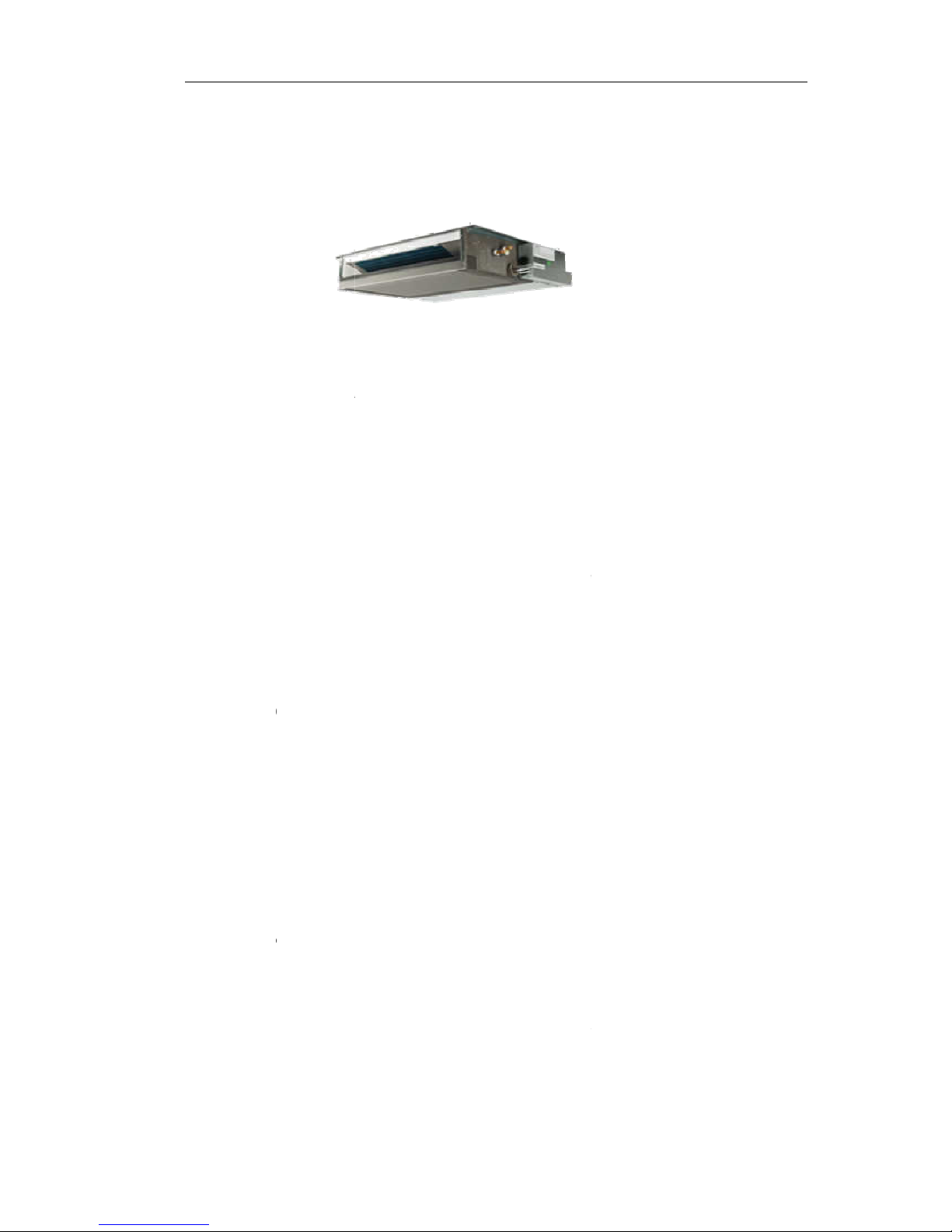
1.1
Duc
eatures
Save Ins
t
The
Optional
k: optional
1
anged betwe
One
High Effi
c
R41
0
24-hour
T
This
Mute Op
e
The
nois
e
Meeting
V
The
spa
c
Feature
s
t Type
Ai
allation Sp
a
indoor unit
c
Static Press
0Pa /30Pa,
en1-80Pa)
, 4
8
unit, mute
o
iency and
E
0
A can prot
e
imer ON a
n
Timer can
b
ration
excellent fa
n
e
.
arious Inst
a
back-air-inl
e
e.
r Conditi
ce
an be instal
l
ure
24K/36K 50
8
K/60K: 80
P
ptional inst
a
nvironment
ct the envir
o
d OFF
e set to aut
o
design en
a
llation Req
u
t type is us
u
1
oner
ed inside th
e
Pa/80Pa(Fo
a/120Pa st
a
llation meth
o
Friendly Ne
w
nment and
d
matically tu
ble the airfl
o
irements
ally to be a
d
ceiling co
n
r
AUD-24UX
4
tic Pressur
e
d.
Refrigeran
o not harm
n the unit o
n
w to be qui
e
opted acco
r
veniently.
SALH1&AU
D
.
t-R410A
to the ozon
e
or off withi
n
t and smoo
t
ding to the
a
1.G
E
-36UX4SAM
H
layer.
a 24-hour
p
h with mini
m
ctual install
a
NERAL
1,freely
eriod.
um
tion
Page 4

1.GENERAL
2
The unit is also installed with down-air-inlet type and the noise will increase about 5-6
dB.
¾ Self Recovery of Power Break
When the power supply is recovered after break, all preset are still effective and the
air-conditioner can run according to the original setting.
¾ Fault Self-diagnose Function
When there is something wrong with the air-conditioner,the micro computer could
diagnose the faults, which can be read from the display and is convenient for
maintenance.
Page 5

C
F
e
¾¾¾¾¾
¾
assette
T
atures
Save Ins
t
The indo
o
High Effi
c
R410A c
a
24-hour
T
This Tim
e
Mute Op
e
The exc
e
Self Rec
o
When th
e
air-condi
t
Fault Sel
f
When th
e
the fault
ype Air
allation Sp
a
r unit can
b
iency and
E
n protect th
imer ON a
n
r can be se
t
ration
llent fan de
s
very of Po
w
power sup
p
ioner can ru
-diagnose
F
re is somet
h
s, which ca
n
Conditio
n
ce
e installed i
n
nvironment
e environm
e
d OFF
to automat
i
ign enable t
er Break
ly is recove
n according
unction
ing wrong
w
be read fro
m
3
er
side the cei
l
Friendly Ne
w
nt and do n
o
cally turn th
e
he airflow to
red after br
e
to the origin
a
ith the air-c
o
the displa
y
ing conveni
e
Refrigeran
t harm to th
unit on or
o
be quiet an
d
ak, all pres
e
l setting.
nditioner, th
and is con
v
ntly.
t-R410A
e ozone lay
e
ff within a 2
4
smooth wi
t
t are still eff
e
e micro co
m
enient for
m
1.G
E
r.
-hour perio
h minimum
n
ctive and t
h
puter could
d
aintenance.
NERAL
d.
oise.
e
iagnose
Page 6

1.GENERAL
4
Ceiling &Floor Air Conditioner
Features
¾ Save Installation Space
The indoor unit’s thickness is only 230mm,can be installed inside the ceiling conveniently.
¾ Flexible Installation Options
According to the actual installation space,The indoor unit can be installed in the ceiling
or on the floor. One unit, Two installation method.
¾ High Efficiency and Environment Friendly
New Refrigerant-R410A
R410A can protect the environment and do not harm to the ozone layer.
¾ 24-hour Timer ON and OFF
This Timer can be set to automatically turn the unit on or off within a 24-hour period.
¾ Mute Operation
The excellent fan design enable the airflow to be quiet and smooth with minimum noise.
¾ Various Refrigerant Pipe Connect Methods
The refrigerant pipe can be connect from 3 different directions(rear,right or top) .More methods,
more conveniently.
¾ Self Recovery of Power Break
When the power supply is recovered after break, all preset are still effective and the
air-conditioner can run according to the original setting.
Page 7

1.GENERAL
5
¾ Fault Self-diagnose Function
When there is something wrong with the air-conditioner, the micro computer could diagnose the
faults, which can be read from the display and is convenient for maintenance.
Page 8

1.GENERAL
6
1.2 Product Lineup
Type Model 18 24 36 48 60
Duct Type AUD- ● ● ● ● ●
Cassette Type AUC- ● ● ● ● ●
Ceiling&Floor
type
AUV- ● ● ● ● ●
Page 9

1.GENERAL
7
1.3 MODEL IDENTIFICATION
A U C -18 U R 4 S Z A A 1
G:Indoor Unit Indetification
S:Refrigement R410A F:Refrigement R22
4:220V-240V/50HZ/1P 6:380V-415V/50HZ/3P
X: Wire Romote Co ntroller R:W ireless Ro m ote C on troller
Cool Capacity:18x10 Btu/h
Air Conditioner
Unit
K:Outdoor Unit Indetification
serial number
U:DC-Invert Heat Pump Type H:Heat Pump Type C :Cooling Only
Type:D-Duct Type,C-Cassette Type,V-Ceiling&Floor Type,W-Outdoor Unit
3
Page 10
1
D
M
I
O
u
M
I
O
u
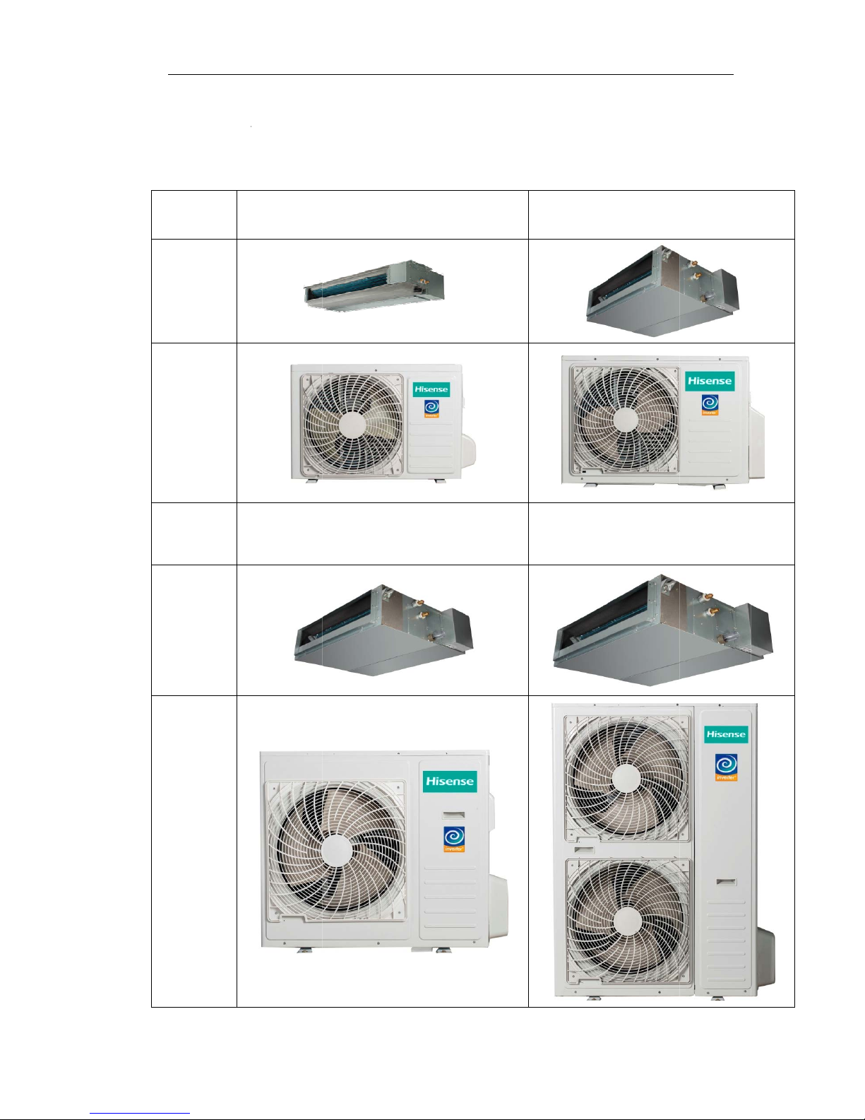
.4 Prod
u
uct Typ
odel
ndoor
tdoor
odel
ndoor
tdoor
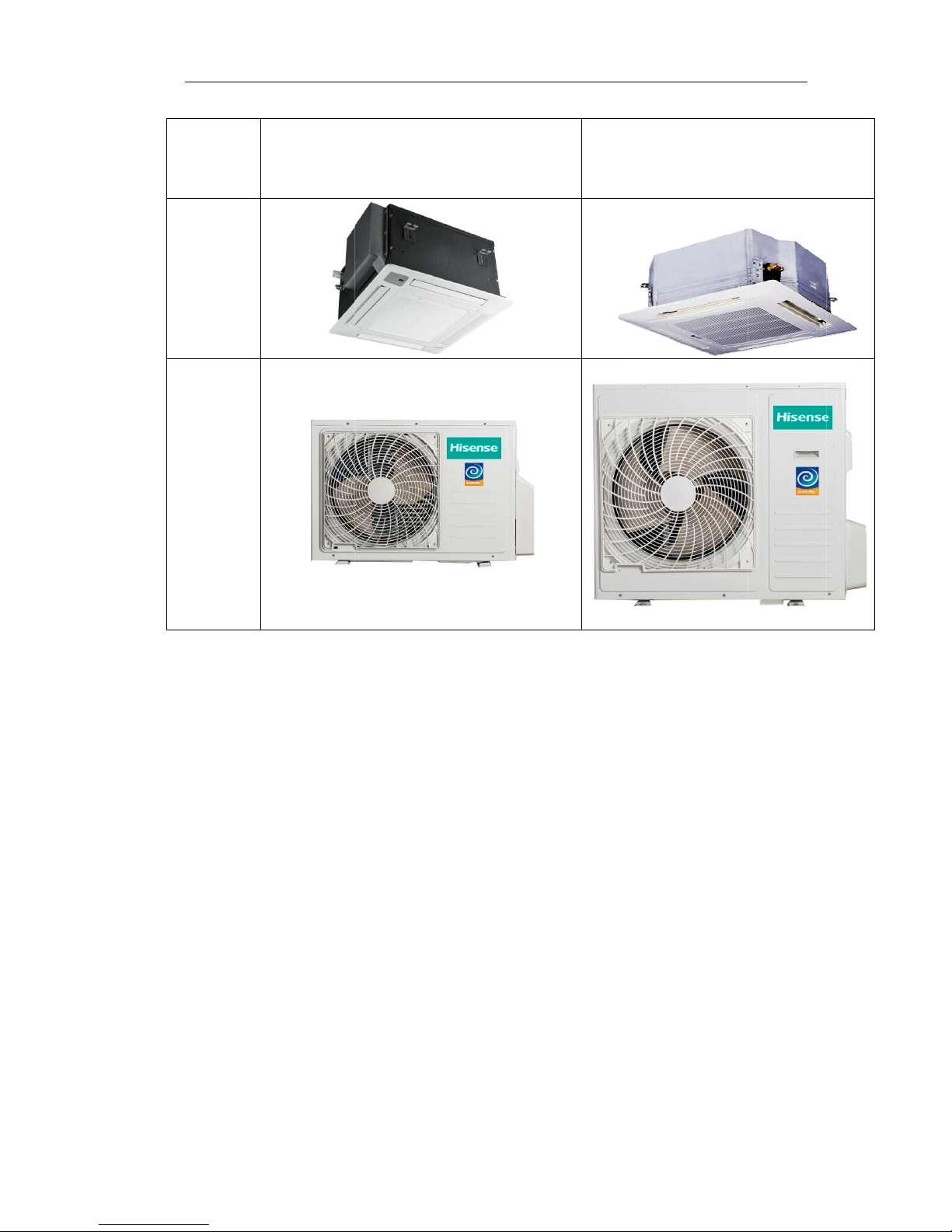
ct Pic
t
e
ure
AUD-18UX
4
AUD-36UX
4
8
SGKL
SAMH
1.G
E
AUD-24UX4
S
AUD-48UX6
S
AUD-48UX6
S
NERAL
ZLH
PHH
PHH
Page 11
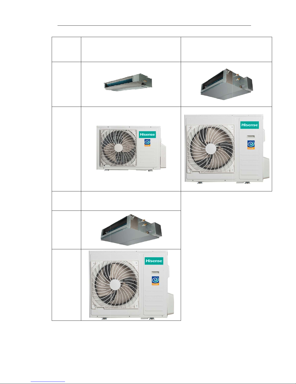
M
I
O
u
M
I
O
u
odel
ndoor
tdoor
odel
ndoor
tdoor
AUD-18UX
4
AUD-36UX
4
9
SZKL1
SAMH1
1.G
E
AUD-24UX4
S
NERAL
ALH1
Page 12
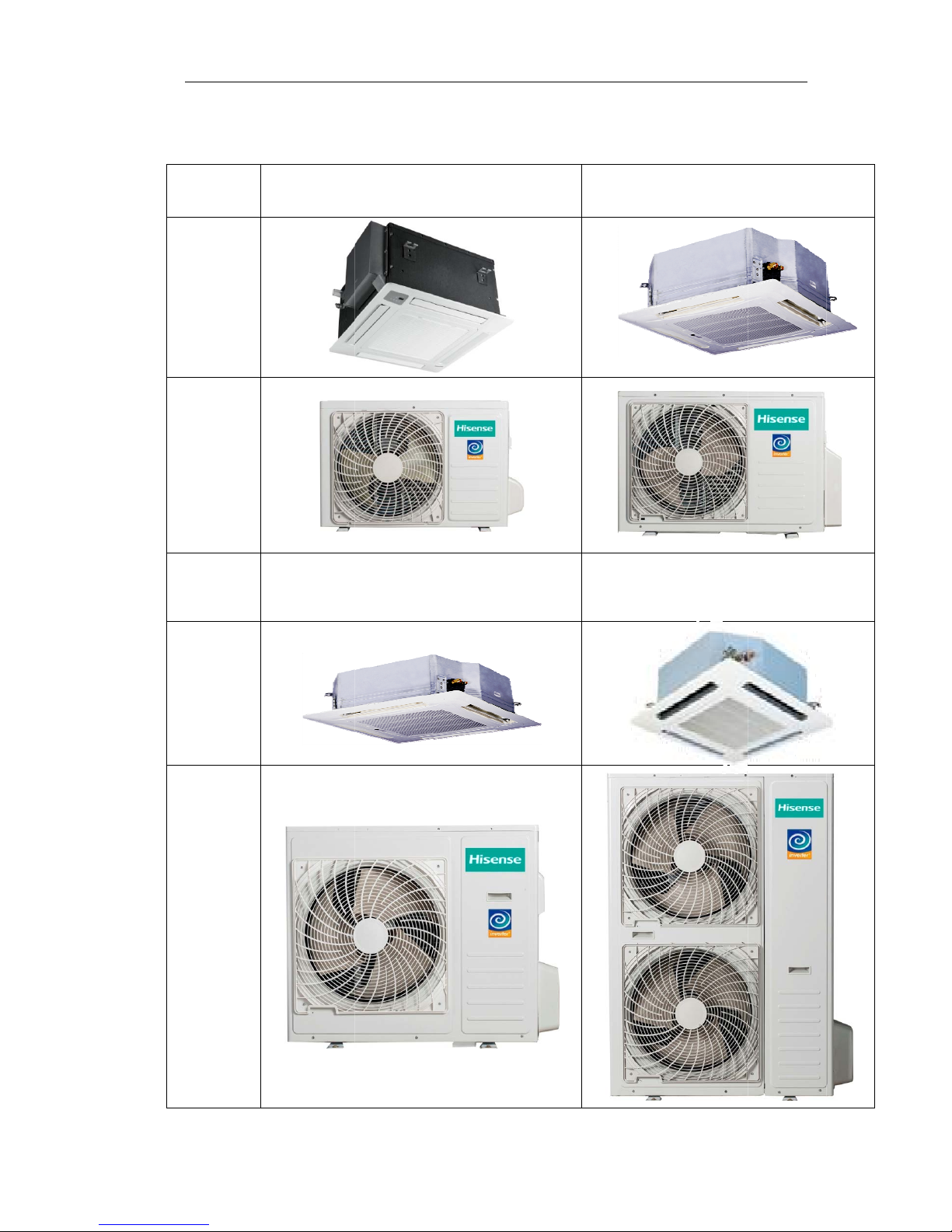
C
a
M
I
O
u
M
I
O
u
ssette T
odel
ndoor
tdoor
odel
ndoor
tdoor
ype
AUC-18UX
4
AUC-36UX
4
10
SGAA
SAEA
1.G
E
AUC-24UX4
S
AUC-48UX6
S
AUC-60UX6
S
NERAL
ZEA
PFA
PFA
Page 13
M
I
O
u
odel
ndoor
tdoor
AUC-18UR
4
11
SZAA1
1.G
E
AUC-24UR4
S
AUC-36UR4
S
NERAL
AEA1
AEA1
Page 14
1.GENERAL
12
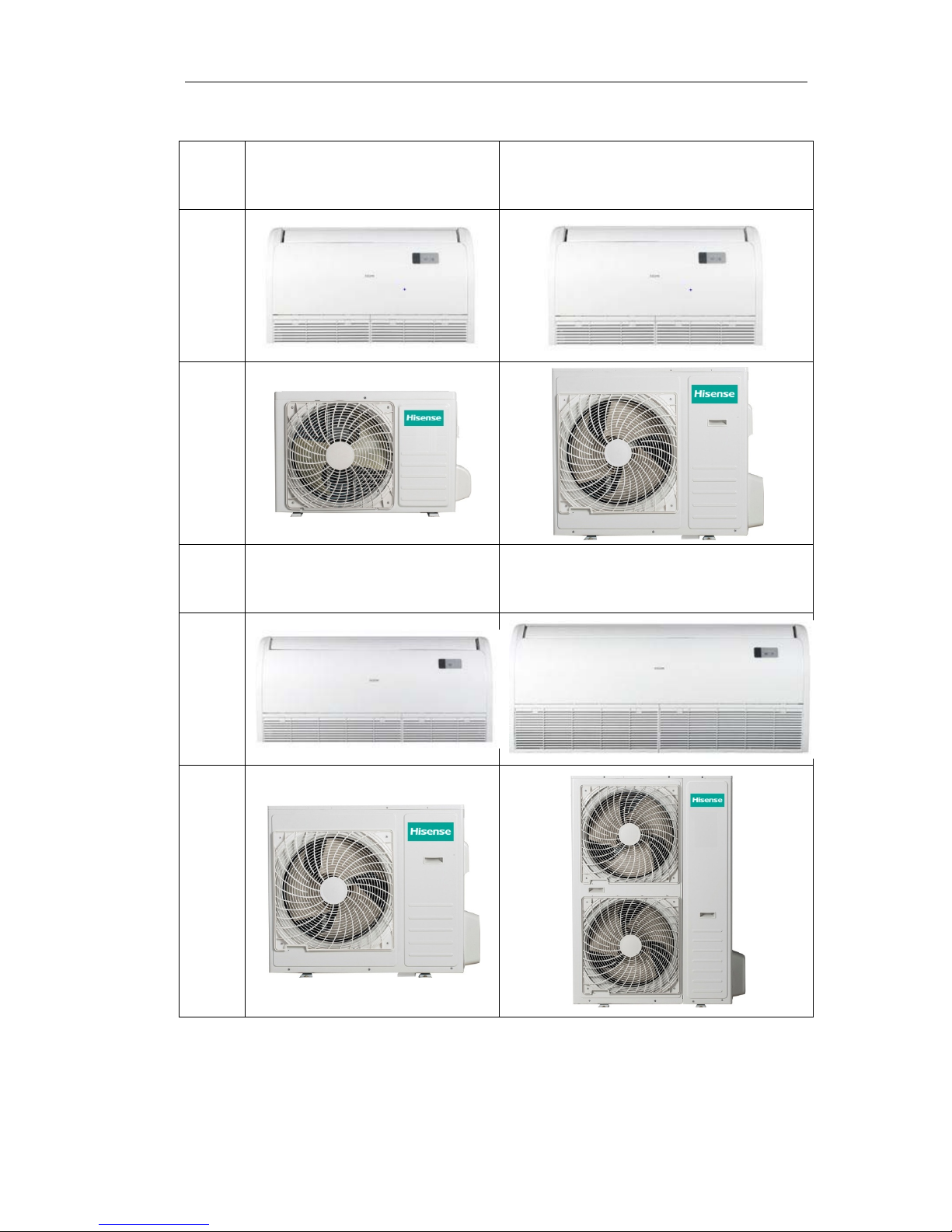
Ceiling &Floor Type
Model AUV-18UR4SZA1 AUV-24UR4SAA1
Indoor
Outdoo
r
Model AUV-36UR4SAB1
AUV-48UR6SPC
AUV-60UR6SPC
Indoor
Outdoo
r
Page 15
1.GENERAL
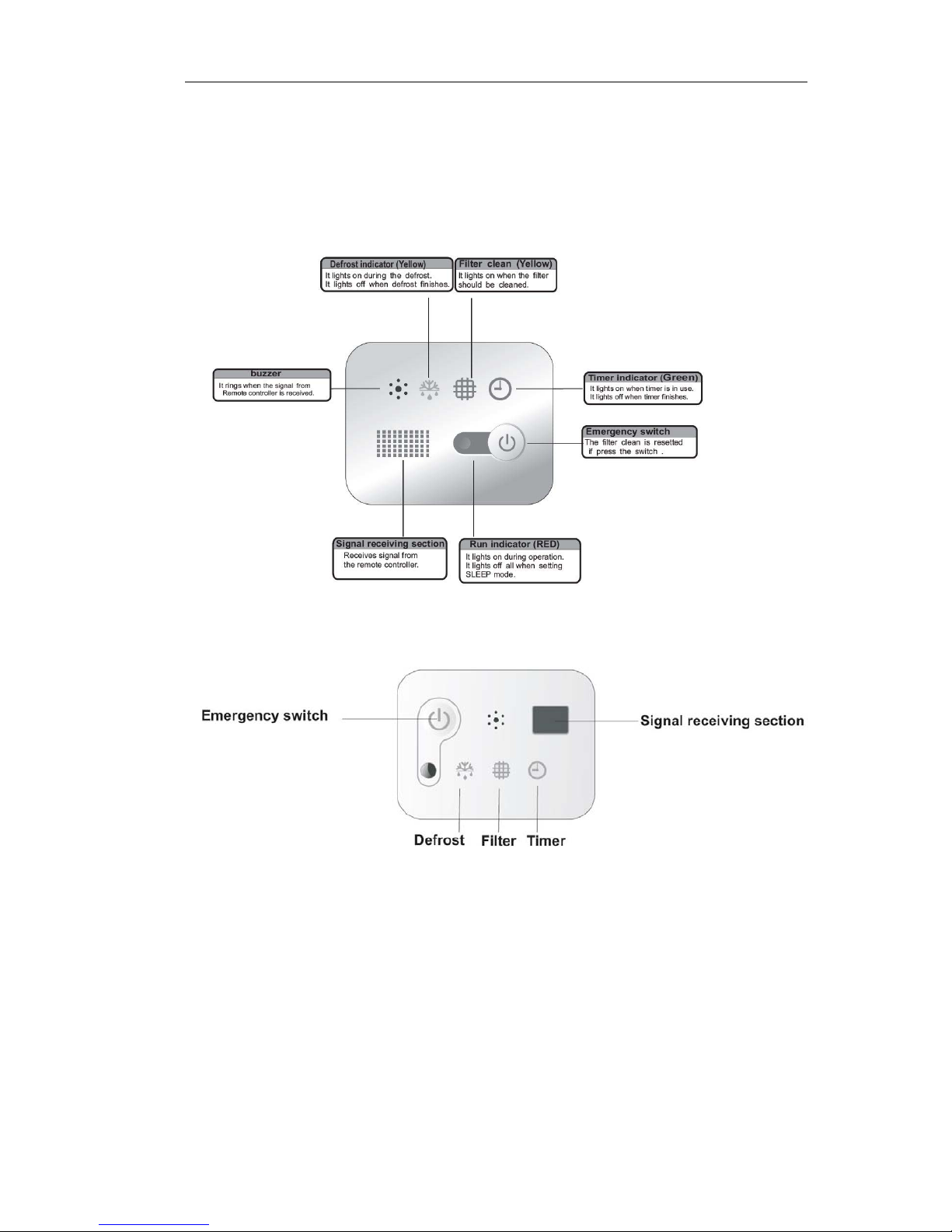
13
DISPLAY PANEL:
Cassette Type
18k
24K,36K,48K,60K
Page 16
1.GENERAL
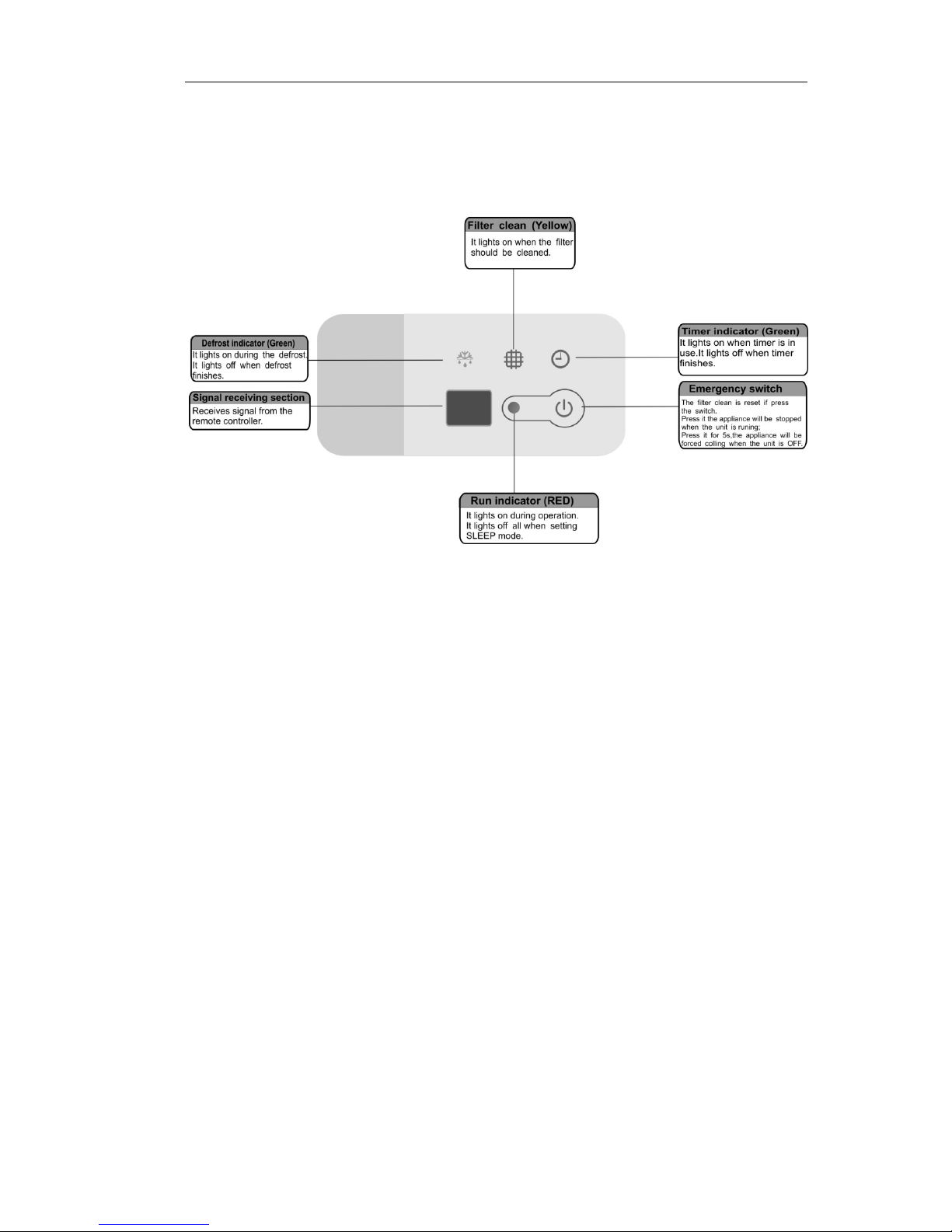
14
Ceiling&Floor type
Page 17
2.SPECIFICATIONS
15
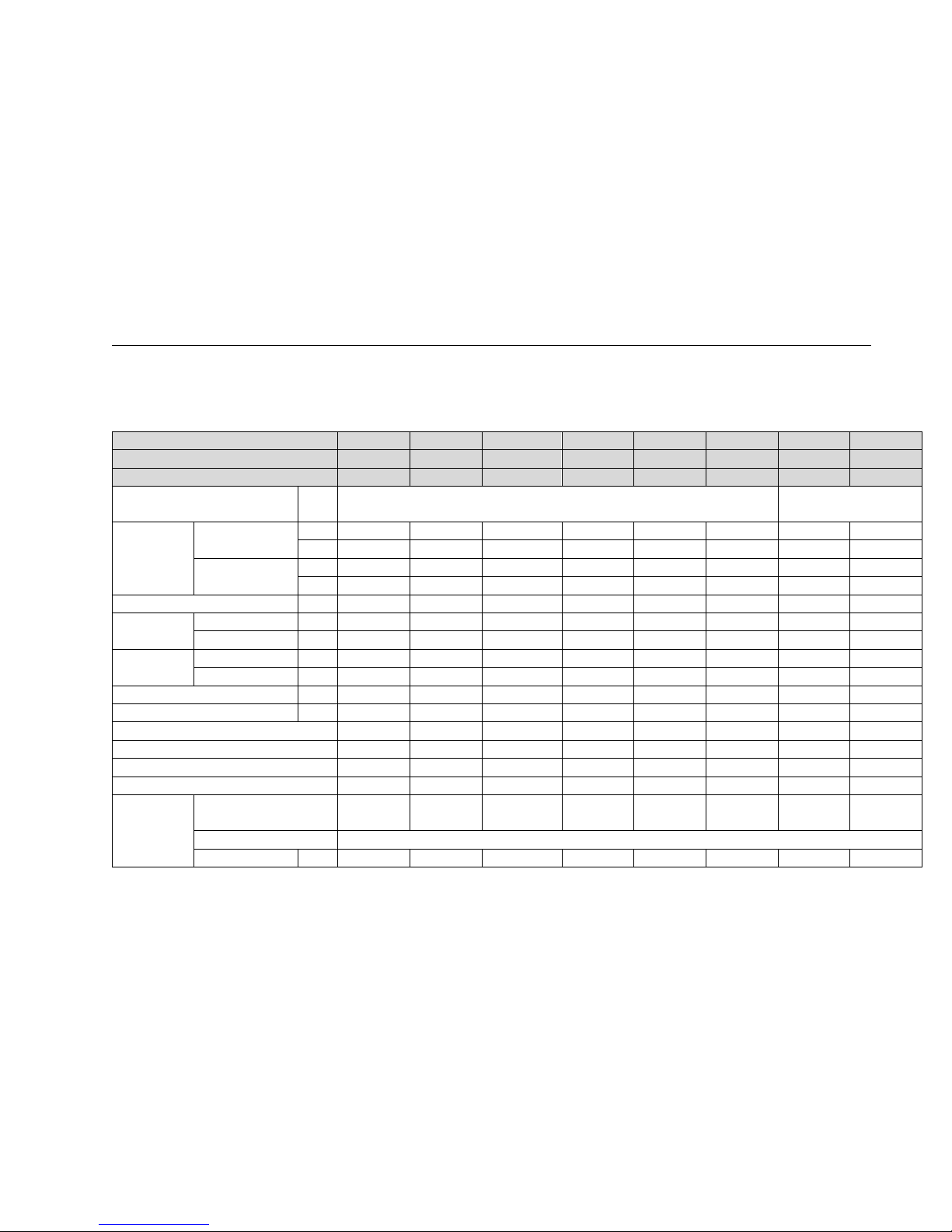
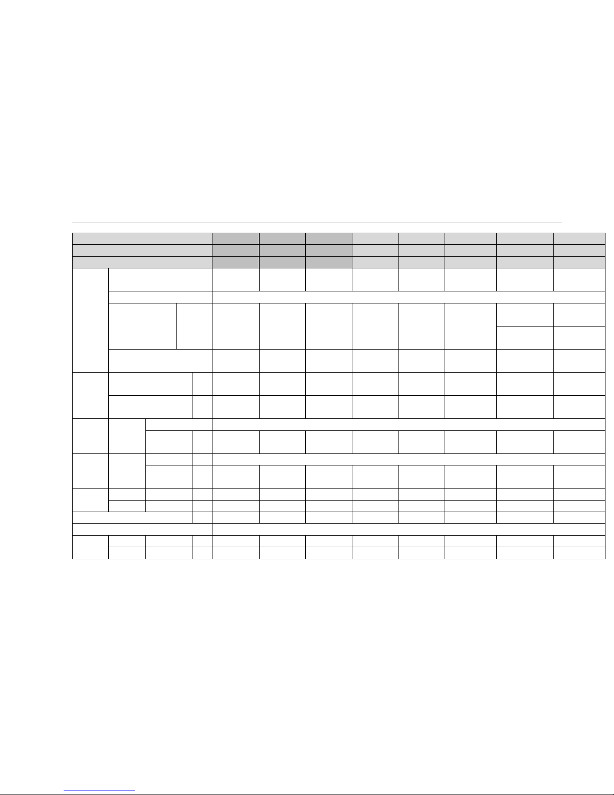
2.Specifications
DuctType
Model AUD-18UX4SZKL1 AUD-24UX4SALH1 AUD-36UX4SAMH1 AUD-18UX4SGKL AUD-24UX4SZLH AUD-36UX4SAMH AUD-48UX6SPHH AUD-60UX6SPHH
Indoor model AUD-18UX4SKL1 AUD-24UX4SLH1 AUD-36UX4SMH1 AUD-18UX4SKL AUD-24UX4SLH AUD-36UX4SMH AUD-48UX4SHH AUD-60UX4SHH
Outdoor model AUW-18U4SZ1 AUW-24U4SA1 AUW-36U4SA1 AUW-18U4SG AUW-24U4SZ AUW-36W4SA AUW-48U6SP AUW-60U6SP
Power supply
Ph-V-H
z
20V-240V ~/50Hz 380V-415V,3N~/50Hz
Capacity
Cooling
kW
5 7 9.2 5 6.4 10 12.6 17
Btu/h 17,000 23,900 31,400 17,000 21,800 34,100 43,000 58,000
Heating
kW 5.6 8.1 11 5.6 7.25 11.5 15 20.5
Btu/h 19,100 27,600 37,500 19,100 24,700 39,200 51,200 70,000
Dehumidification L/h 1.4 1.8 2.4 1.4 1.8 2.4 3.3 4.5
Rated input
Cooling kW 1.5 2.3 3.05 1.552 1.99 3.11 3.92 5.295
Heating kW 1.6 2.65 3.25 1.55 2 3.19 4.15 5.65
Rated Current
Cooling A 6.8 10.2 13.9 6.9 8.9 13.5 7.5 10.8
Heating A 7.3 11.5 13.1 6.9 8.9 13.9 8 11.3
Max. input kW 2.5 3.6 5.1 2.58 3 5.23 6.2 9.38
Max.Current A 12 15.9 22.5 11.5 13.5 22.78 13 17.7
EER/COP 3.33/3.5 3.04/3.06 3.04/3.06 3.22/3.61 3.22/3.63 3.22/3.61 3.21/3.61 3.21/3.63
SEER/SCOP 5.6/3.8 5.6/3.8 5.1/3.8 / / / / /
Cooling Energy Class A+ A+ A A A A A A
Heating Energy Class A A A A A A A A
Compressor
Model
DA131S1B-28FZ DA230S2C-31M
T
DA250S2C-30MT
DA130S1C-20FZ ATL165SD-C9AU DA250S2C-30M
T
TNB306FPNMC LNB42FSAMC
Type Rotary
Winding resistance Ω 0.55(20℃) 0.73 (at20℃) 055(20℃) 0.95(20℃) 0.59 0.95(20℃) U-V: U-V:
Page 18
2.SPECIFICATIONS
16
Model AUD-18UX4SZKL1 AUD-24UX4SALH1 AUD-36UX4SAMH1 AUD-18UX4SGKL AUD-24UX4SZLH AUD-36UX4SAMH AUD-48UX6SPHH AUD-60UX6SPHH
Indoor model AUD-18UX4SKL1 AUD-24UX4SLH1 AUD-36UX4SMH1 AUD-18UX4SKL AUD-24UX4SLH AUD-36UX4SMH AUD-48UX4SHH AUD-60UX4SHH
Outdoor model AUW-18U4SZ1 AUW-24U4SA1 AUW-36U4SA1 AUW-18U4SG AUW-24U4SZ AUW-36W4SA AUW-48U6SP AUW-60U6SP
2433;U-W :2433; 2433;U-W :2433;
V-W: 2.304(at
25℃)
V-W: 2.304(at
25℃)
Brand GMCC GMCC GMCC GMCC HIGHLY GMCC
MITSUBISHI
ELECTRIC
MITSUBISHI
ELECTRIC
Fan motor
Indoor Model
YSK110-40-4-A(
HS16)
SIC-70CW-F195
-1
SIC-101CW-F1246
-1
YSK110-40-4-A(
HS16)
Y6S419C56 Y7S423C024 Y7S423C032 Y7S423C032
Outdoor Model ARW4401QH
SIC-71FW-D812
1-1
SIC-71FW-D8121-
1
YDK29-6I-22 YDK70-6H-3 YDK95-6-9043
YDK65-6-9024
YDK65-6-9061
YDK65-6-9024
YDK65-6-9061
Fan Indoor
type
centrifugal fan
Speed
Hi/Med/Low
r.p.m
1130/850/950(10
Pa)
1000/910/810(30
Pa)
1060/980/900(30P
a)
1130/850/950(10
Pa)
1070/990/860(50
Pa)
1150/1070/1020(
50Pa)
1250/1200/1100(
120Pa)
1250/1200/1100(
120Pa)
Fan speed Outdoor
type r.p.m
tube-axial
Speed
Hi/Med/Low
r.p.m
0-810 0-810 0-810 900/750/500 840/780/560 800/640/540 700/600/500 700/600/500
Air circulation
Indoor Hi/Med/Low m³/h 850 1100 1800 850 1100 1700 2000 2000
Outdoor Hi/Med/Low m³/h -- -- -- -- -- -- -- --
Static Pressure(*Default Setting) Pa 10*/30
30*/(1~80
optional)
30*/(1~80
optional))
10*/30 50*/80 50*/80 80*/120 80*/120
Operating control Wireless Remote control-J1-05(E)
Dimensions
Indoor L×W×H mm 1170×447×190 900×720×270 1300×720×270 1170×447×190 900×720×270 1300×720×270 1300×800×350 1300×800×350
Outdoor L×W×H mm 900×300×640 950×340×840 950×340×840 800×260×570 900×300×640 940×340×840 950×340×1386 950×340×1386
Packing
Indoor L×W×H mm 1340×580×236 1170X340X870 1570X340X870 1340×580×236 1170X340X870 1570X340X870 1550X940X410 1550X940X410
Outdoor L×W×H mm 1050×400×700 1110×460×980 1110×460×980 950×365×645 1050×700×400 1110×460×980 1110×460×1530 1110×460×1530
Weight Indoor Net/Gross kg 24/28 32/37 43/51 24/28 32/37 38/43 50/58 50/58
Page 19
2.SPECIFICATIONS
17
Model AUD-18UX4SZKL1 AUD-24UX4SALH1 AUD-36UX4SAMH1 AUD-18UX4SGKL AUD-24UX4SZLH AUD-36UX4SAMH AUD-48UX6SPHH AUD-60UX6SPHH
Indoor model AUD-18UX4SKL1 AUD-24UX4SLH1 AUD-36UX4SMH1 AUD-18UX4SKL AUD-24UX4SLH AUD-36UX4SMH AUD-48UX4SHH AUD-60UX4SHH
Outdoor model AUW-18U4SZ1 AUW-24U4SA1 AUW-36U4SA1 AUW-18U4SG AUW-24U4SZ AUW-36W4SA AUW-48U6SP AUW-60U6SP
Outdoor Net/Gross kg 45/51 69/73 70/74 35.5/39 50/56 70/74 101/107 108/112
Noise lever
Indoor Hi/Med/Low dB(A)
--/54(SOUND
POWER)
--/61(SOUND
POWER)
--/56(SOUND
POWER)
--/41 43/49 43/51 49/53 49/53
Outdoor Hi/Med/Low dB(A)
--/62(SOUND
POWER)
--/65(SOUND
POWER)
--/70(SOUND
POWER)
--/56 53/58 --/58 --/60 --/60
Refrigerant piping
Gas/Liquid mm
12.7/6.35 15.88/9.52 15.88/9.52 12.7/6.35 15.88/9.52 15.88/9.52 19.05/9.52 19.05/9.52
Max. refrigerant pipe
length
m
20 30 30 20 30 30 50 50
Max. difference in level m 10 20 20 10 15 15 30 30
Connection method Flare
Connection Power wiring mm2 3 core x 1.5 3 core x2.5 3 core x2.5 3 core x1.5 3 core x2.5 3 core x2.5 5 core x2.5 5 core x2.5
wiring Signal wiring mm2 4core x0.75 4core x0.75 4core x0.75 4core x0.75 4core x0.75 4core x0.75 4core x0.75 4core x0.75
Refrigerant charge(R410a) k g 1.4 1.68 2.1 1.27 1.5 2.1 3 3.5
Throttle Type EEV EEV EEV EEV EEV EEV EEV EEV
Ambient temp ℃
Cooling -15~48
Heating -10~24
Page 20
2.SPECIFICATIONS
18
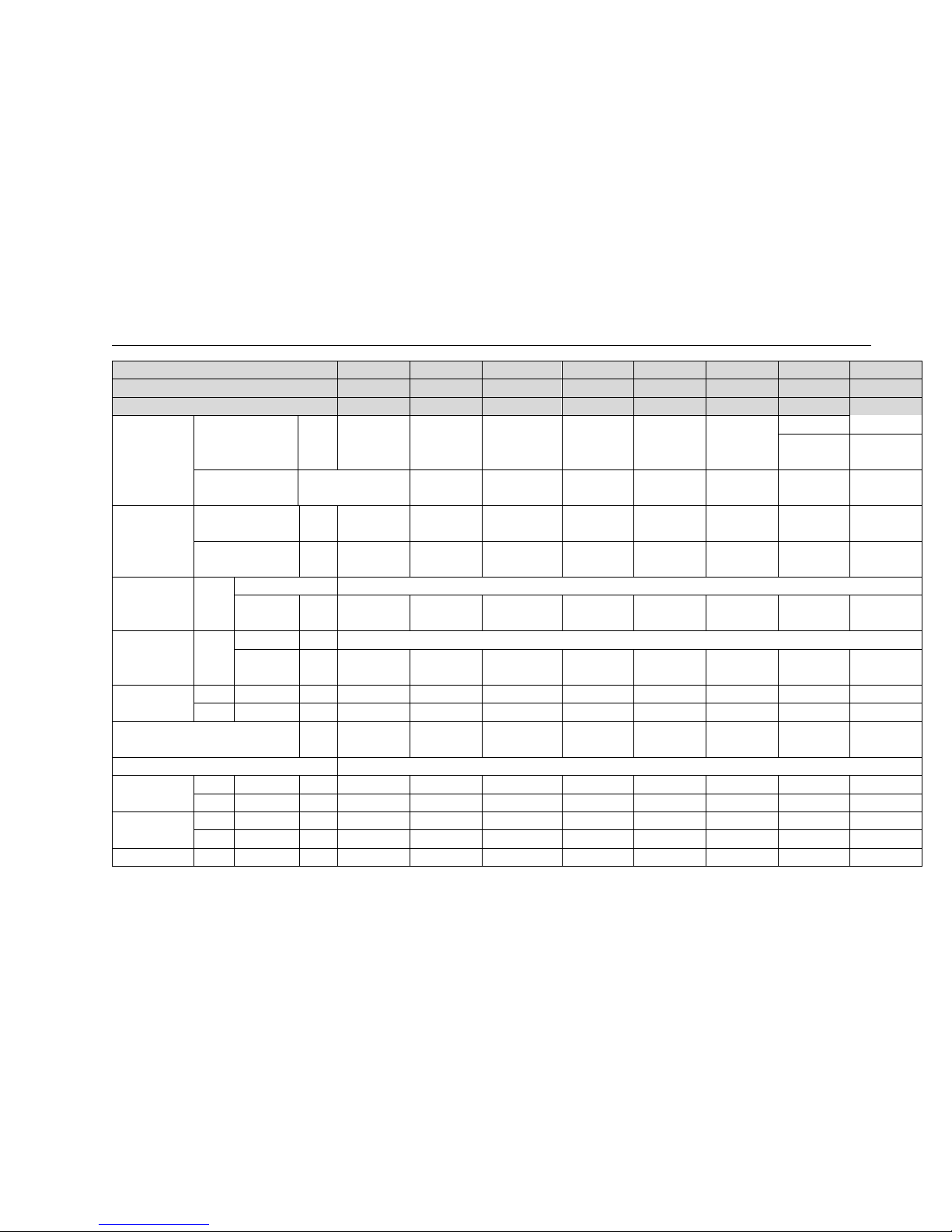
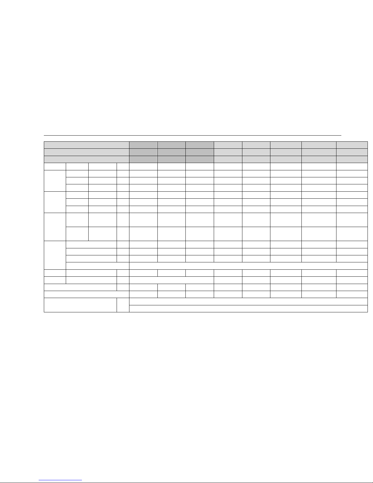
Cassettetype
Model AUC-18UR4SZAA1 AUC-24UR4SAEA 1 AUC-36UR4SAEA1 AUC-18UX4SGAA AUC-24UX4SZEA
AUC-36UX4SAEA AUC-48UX6SPFA AUC-60UX6SPFA
Indoor model AUC-18UR4SAA1 AUC-24UR4SEA1 AUC-36UR4SEA1 AUC-18UX4SAA AUC-24UX4SEA
AUC-36UX4SEA AUC-48UX4SFA AUC-60UX4SFA
Outdoor model AUW-18U4SZ1 AUW-24U4SA1 AUW-36U4SA1 AUW-18U4SG AUW-24U4SZ
AUW-36W4SA AUW-48U6SP AUW-60U6SP
Power supply Ph-V-Hz 20V-240V ~/50Hz 380V-415V,3N~/50Hz
Capacity
Cooling
kW
5(1.2-6.5) 7.0(2.2-8.0) 9.5(3.6~10.5) 5 6.4 10 12 17
Btu/h
17,100(4,100-22
,200)
23,900
(7,500-27,300)
32,400
(12,300-35,800) 17000 21800 34100 41000 58000
Heating
kW
5.6(1.8-7.2) 8.2(2.5-10) 11.0(3.05~13.8) 5.6 7 11.5 15 20
Btu/h
19,100(6,100-24
,600)
28,000
(8,500-34,100)
37,500
(10,400-47,100) 19100 23900 39200 51200 68200
Dehumidification L/h —— —— —— —— —— —— —— ——
Rated input
Cooling kW
1.49(0.40~
2.25)
2.3(0.40~3.6) 3.07(0.4~4.2) 1.552 1.91 3.07 3.72 5.095
Heating kW 1.75(0.38~2.15) 2.73(0.38~3.6) 3.10(0.38~4.2) 1.55 1.92 3.15 3.95 5.45
Rated
Current
Cooling A
6.6 10.1 13.4 6.9 8.5 13.36 6.5 6.5
Heating A 7.8 12.2 13.5 6.89 8.5 13.76 7 7
Max. input
Cooling kW 2.5 3.6 4.25 2.421 2.92 4.55 5.32 8.5
Heating kW 2.5 3.6 4.25 2.581 2.72 4.85 5.92 9.1
Max.Current
Cooling A 12 15.5 20 9.9 13.1 19.83 10.7 10.7
Heating A 12 15.5 20 11.47 12.1 21.13 11.7 11.7
EER/COP 3.36/3.20 3.04/3.0 3.09/3.55 3.22/3.61 3.35/3.64 3.26/3.65 3.39/3.8 3.34/3.67
SEER/SCOP 5.6/3.8 5.6/3.8 5.1/3.8 / / / / /
Cooling Energy Class
A+ A+ A
A A A A A
Heating Energy Class
A A A
A A A A A
Page 21
2.SPECIFICATIONS
19
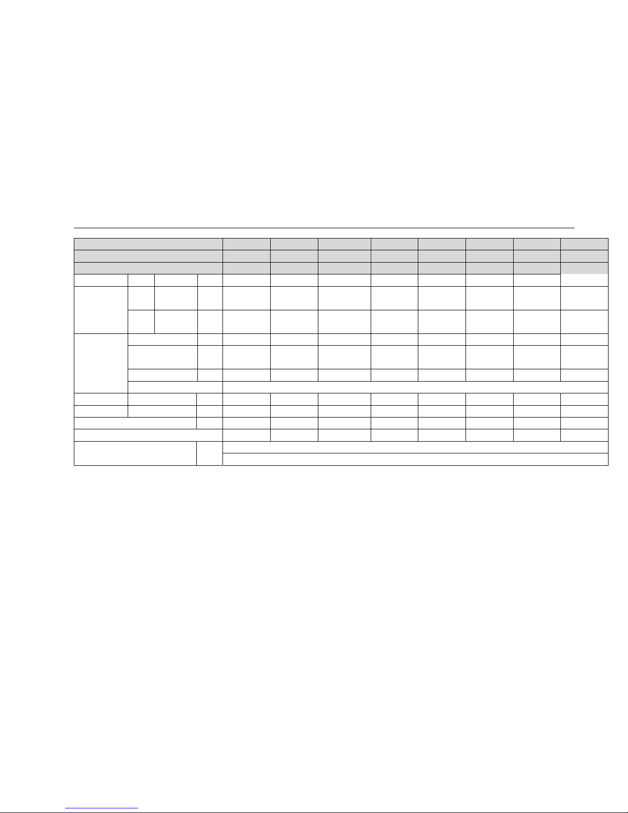
Model AUC-18UR4SZAA1 AUC-24UR4SAEA 1 AUC-36UR4SAEA1 AUC-18UX4SGAA AUC-24UX4SZEA
AUC-36UX4SAEA AUC-48UX6SPFA AUC-60UX6SPFA
Indoor model AUC-18UR4SAA1 AUC-24UR4SEA1 AUC-36UR4SEA1 AUC-18UX4SAA AUC-24UX4SEA
AUC-36UX4SEA AUC-48UX4SFA AUC-60UX4SFA
Outdoor model AUW-18U4SZ1 AUW-24U4SA1 AUW-36U4SA1 AUW-18U4SG AUW-24U4SZ
AUW-36W4SA AUW-48U6SP AUW-60U6SP
Compressor
Model
DA131S1B-28FZ DA230S2C-31MT DA250S2C-30M
T
DA130S1C-20FZ ATL165SD-C9A
U
DA250S2C-30MT TNB306FPNMC LNB42FSAMC
Type Rotary
Winding resistance Ω 0.55(20℃) 0.73 (at20℃) 055(20℃) 0.95(20℃) 0.59 0.95(20℃)
U-V:
2433;U-W :2433;
U-V:
2433;U-W :2433;
V-W: 2.304(at 25℃)
V-W: 2.304(at
25℃)
Brand GMCC GMCC GMCC GMCC HIGHLY GMCC
MITSUBISHI
ELECTRIC
MITSUBISHI
ELECTRIC
Fan motor
Indoor
Mode
l
EHDS50AQ ARW5901QH EHDS50AQH YDK95-28-4-B ARW5901QH EHDS50AQH SIC72FW-D8124-2B
SIC72FW-D8124-2
B
Outdoor
Mode
l
ARW4401QH
SIC-71FW-D812
1-1
SIC-71FW-D812
1-1
YDK29-6I-22 YDK70-6H-3 YDK95-6-9043
YDK65-6-9024
YDK65-6-9061
YDK65-6-9024
YDK65-6-9061
Fan Indoor
type
centrifugal fan
Speed
Hi/Med/Low
r.p.m
980/840/720 440/380/370 630/520/460 980/840/720 440/370/280 630/520/460 630/520/460 630/520/460
Fan speed Outdoor
type r.p.m tube-axial
Speed
Hi/Med/Low
r.p.m
0-810 0-810 0-810 900/750/500 840/780/560 800/640/540 700/600/500 700/600/500
Air
circulation
Indoor Hi/Med/Low m³/h 850 1100 1600 850 1100 1600 2000 2400
Outdoor Hi/Med/Low m³/h -- -- -- -- -- -- -- --
Static Pressure(*Default Setting) Pa 0 0 0 0 0 0 0 0
Operating control Wireless Remote control(J1-05)
Dimensions
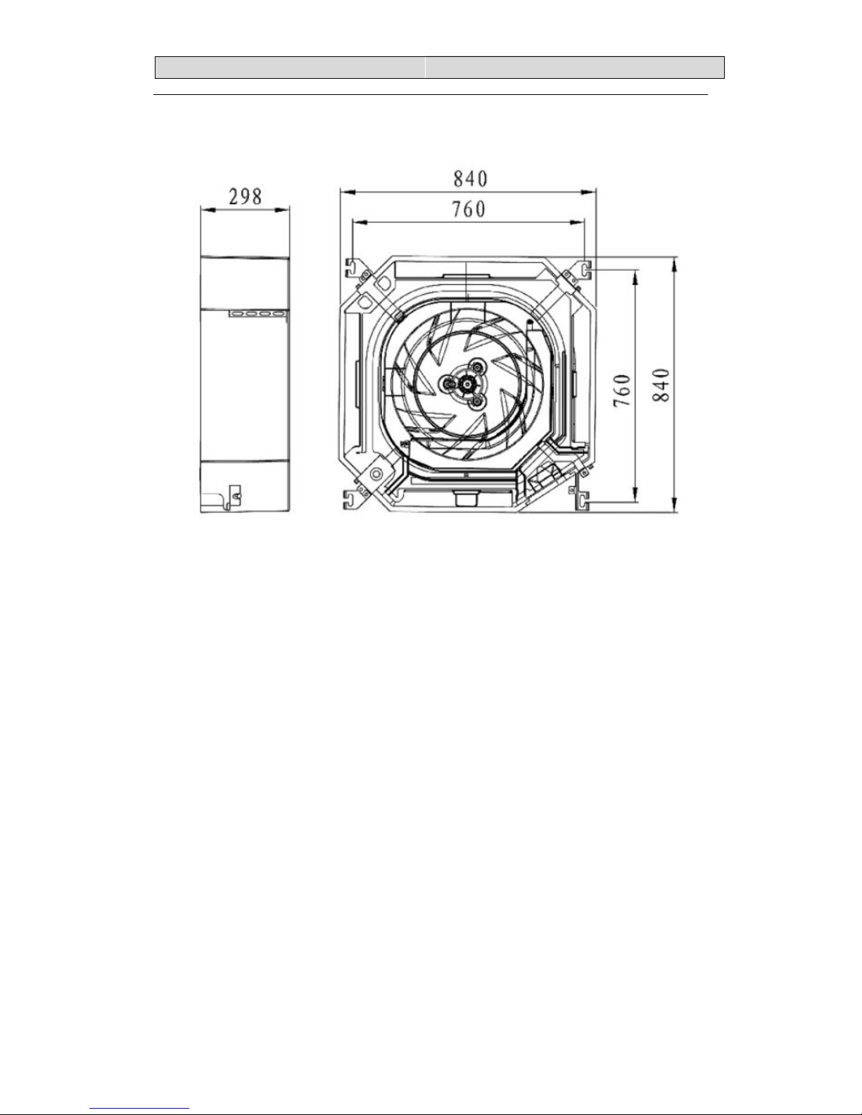
Indoor L×W×H mm 650×570×270 840×840×248 840×840×248 650×570×270 840×840×248 840×840×248 840×840×298 840×840×298
Outdoor L×W×H mm 900×300×640 950×340×840 950×340×840 800×260×570 900×300×640 940×340×840 950×340×1386 950×340×1386
Page 22
2.SPECIFICATIONS
20
Model AUC-18UR4SZAA1 AUC-24UR4SAEA 1 AUC-36UR4SAEA1 AUC-18UX4SGAA AUC-24UX4SZEA
AUC-36UX4SAEA AUC-48UX6SPFA AUC-60UX6SPFA
Indoor model AUC-18UR4SAA1 AUC-24UR4SEA1 AUC-36UR4SEA1 AUC-18UX4SAA AUC-24UX4SEA
AUC-36UX4SEA AUC-48UX4SFA AUC-60UX4SFA
Outdoor model AUW-18U4SZ1 AUW-24U4SA1 AUW-36U4SA1 AUW-18U4SG AUW-24U4SZ
AUW-36W4SA AUW-48U6SP AUW-60U6SP
Panel L×W×H mm 650×650×30 950×950×37 950×950×37 650×650×30 950×950×37 950×950×37 950×950×37 950×950×37
Packing
Indoor L×W×H mm
770×750×310 930×930×290 930×930×290 770×750×310 930×930×290 930×930×290 930×930×340 930×930×340
Outdoor L×W×H mm 1050×400×700 1110×460×980 1110×460×980 940×360×640 1050×700×400 1110×460×980 1110×460×1530 1110×460×1530
Panel L×W×H mm 730×730×130 1010×990×95 1010×990×115 730×730×130 1010×990×95 1010×990×95 1010×990×95 1010×990×95
Weight
Indoor Net/Gross kg
21/25.5 24/30 26/32 21/25.5 24/30 26/32 29/35 29/35
Outdoor Net/Gross kg 45/51 69/73 70/74 35.5/39 50/56 70/74 101/107 108/112
Panel Net/Gross kg 2.4/5 6/7.5 6/7.5 2.4/5 6/7.5 6/7.5 6/7.5 6/7.5
Noise lever
Indoor
Low/Hi/sound
power
Db
--/48/58 36/42/53 --/50/61 --/48 36/42 --/50 43/49 43/49
Outdoor
Low/Hi/sound
power
Db 45/50/62 --/58/70 --/58/70 --/56 53/58 --/58 --/60 --/60
Refrigerant
piping
Gas/Liquid mm
12.7/6.35 15.88/9.52 15.88/9.52 12.7/6.35 15.88/9.52 15.88/9.52 19.05/9.52 19.05/9.52
Max. refrigerant pipe length m 20 30 30 20 30 30 50 50
Max. difference in level m 10 20 20 10 15 15 30 30
Connection method Flare
Connection Power wiring mm23 core x1.5 3 core x2.5 3 core x2.5 3 core x1.5 3 core x2.5 3 core x2.5 5 cor e x2.5 5 core x2.5
wiring Signal wiring mm
2
4 core shielded wire x 0.75 4core x0.75 4core x0.75 4core x0.75 4core x0.75 4core x0.75
Refrigerant charge(R410a) kg 1.4 1.68 2.1 1.27 1.5 2.1 3 3.5
Throttle Type EEV EEV EEV EEV EEV EEV EEV EEV
Ambient temp ℃
Cooling -15~48
Heating -10~24
Page 23
2.SPECIFICATIONS
21
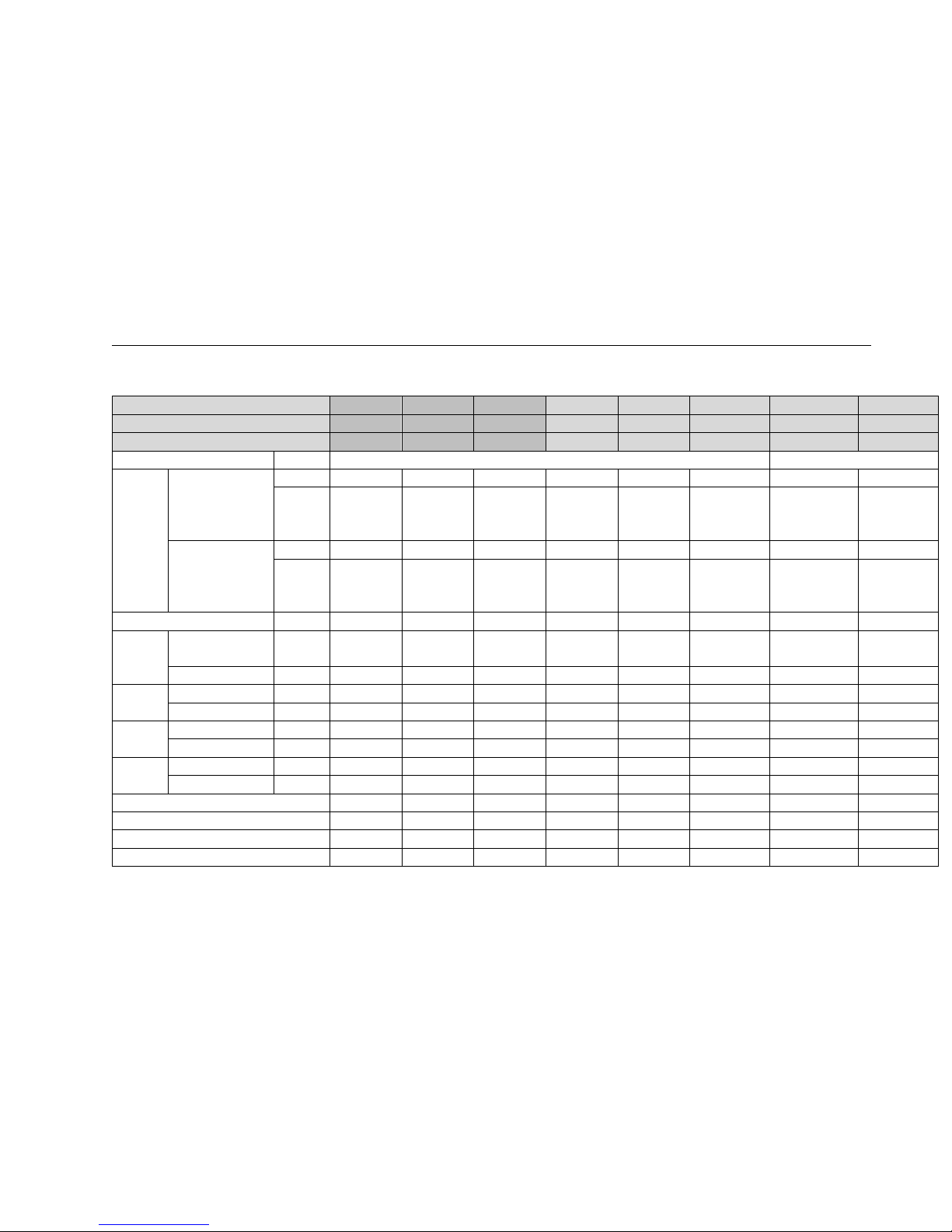
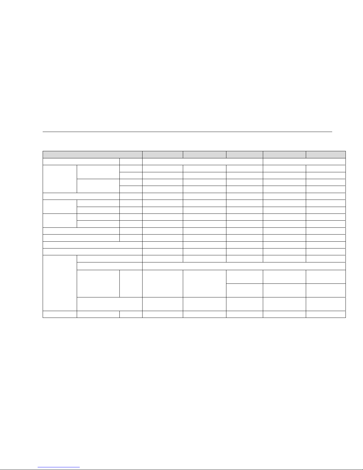
Ceiling&Floortype
Model AUV-18UR4SZA1 AUV-24UR4SAA1 AUV-36UR4SAB1 AUV-48UR6SPC AUV-60UR6SPC
Power supply Ph-V-Hz
1N,220V-240V/50Hz 3N~,380V-415V/50Hz
Capacity
Cooling
kW
5.0 7.0 9.2 12.6 17.0
Btu/h
17,000 23,900 31,400 43,000 58,000
Heating
kW
5.8 8.6 11.0 15.3 20.5
Btu/h
19,800 29,000 37,500 52,200 70,000
Dehumidification L/h
1.4 1.8 2.4 3.3 4.5
Rated input
Cooling kW
1.55 2.3 3.05 3.92 5.295
Heating kW
1.75 2.77 3.3 4.2 5.65
Rated Current
Cooling A
7.0 10.1 13.9 7.5 10.8
Heating A
8.0 13.0 15.0 8.0 11.3
Max. input kW
2.5 3.6 5.1 6.2 9.38
Max.Current A
12.0 15.9 22.5 13.0 17.7
EER/COP
3.33/3.31 3.04/3.10 3.02/3.33 3.21/3.64 3.21/3.61
SEER/SCOP
5.6/3.8 5.6/3.8 5.1/3.8 / /
Compressor
Model
DA131S1B-28FZ DA230S2C-31MT DA250S2C-30MT TNB306FPNMC LNB42FSAMC
Type
Rotary
Winding resistance Ω
M:2.1,A:2.81 M:1.37,A:1.7
U-V:
2.806;U-W :2.806;
U-V: 2433;U-W :2433; U-V: 2433;U-W :2433;
V-W: 2.651 (at
25℃)
V-W: 2.304(at 25℃) V-W: 2.304(at 25℃)
Brand
GMCC GMCC GMCC MITSUBISHI ELECTRIC
MITSUBISHI
ELECTRIC
Fan motor Indoor Model
YSK110-22-4-A( HS24) SIC-70CW-F1100-6 SIC-70CW-F1140-3 Y7S423C032 Y7S423C032
Page 24
2.SPECIFICATIONS
22
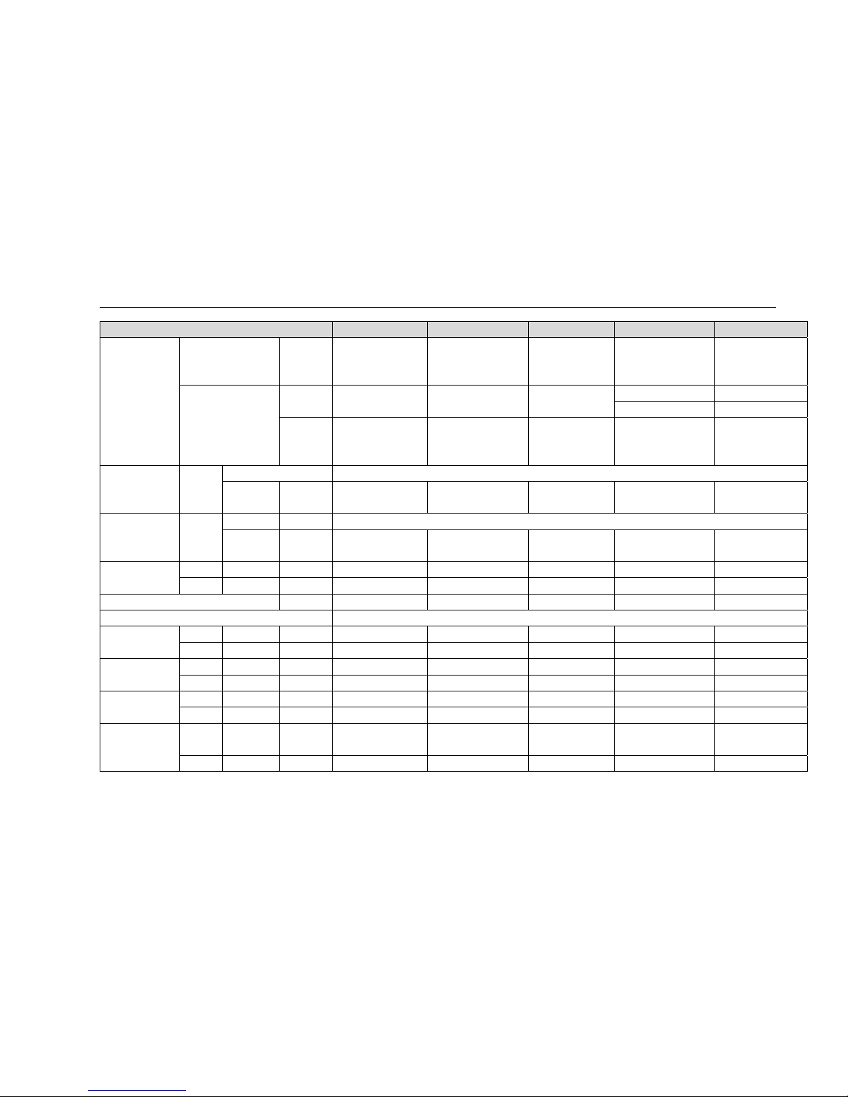
Model AUV-18UR4SZA1 AUV-24UR4SAA1 AUV-36UR4SAB1 AUV-48UR6SPC AUV-60UR6SPC
Winding
resistance
(at20℃)
M:187A:245,60,33,143 M:209.4;A:245,60,33,143 M:75;A:97.5 M:79.7;A:59.4,20.2,108
M:79.7;A:59.4,20.2,10
8
Outdoor
Model
ARW4401QH SIC-71FW-D8121-1 SIC-71FW-D8121-1
YDK65-6-9024 YDK65-6-9024
YDK65-6-9061 YDK65-6-9061
Winding
resistance
(at20℃)
M:231.5;A:168 M:78;A:36.2,51.5,109.2 M:59.1;A:85.8
M:83;A1:23.4A2:14A1:6
3.5
M:83;A1:23.4A2:14A1:
63.5
Fan Indoor
type
centrifugal fan
Speed
Hi/Med/Low
r.p.m
630/720/850 910/1030/1150 1080/1160/1220 1000/1100/1200 1000/1100/1200
Fan speed Outdoor
type r.p.m
tube-axial
Speed
Hi/Med/Low
r.p.m
0-810 0-810 0-810 500/600/700 500/600/700
Air circulation
Indoor Hi/Med/Low m³/h
800 1100 1600 2000 2000
Outdoor Hi/Med/Low m³/h
-- -- -- -- --
Static Pressure(*Default Setting) Pa
0 0 0 0 0
Operating control
Wireless Remote control-J1-05(E)
Dimensions
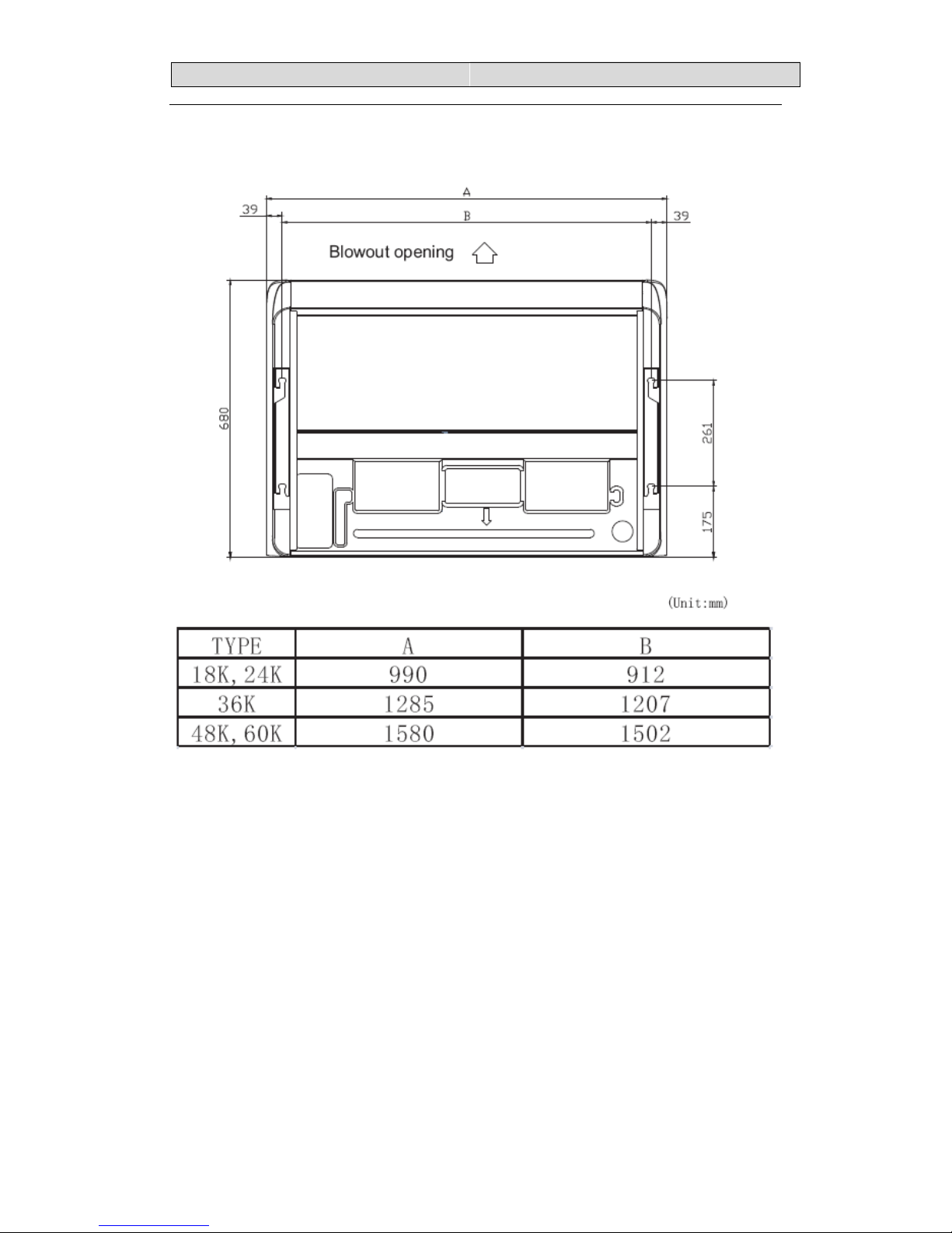
Indoor L×W×H mm
990×680×230 990×680×230 1290×680×230 1580×680×230 1580×680×230
Outdoor L×W×H mm
900×300×640 950×340×840 950×340×840 950×340×1386 950×340×1386
Packing
Indoor L×W×H mm
1100×820×350 1100×820×350 1400×820×350 1690×820×350 1690×820×350
Outdoor L×W×H mm
1050×700×400 1110×460×980 1110×460×980 1110×460×1530 1110×460×1530
Weight
Indoor Net/Gross kg
27/33 30/35 37/44 47/54 47/54
Outdoor Net/Gross kg
45/51 69/73 70/74 101/107 108/112
Noise lever
Indoor Hi/Med/Low dB(A)
--/54(SOUND POWER) --/63(SOUND POWER)
--/64(SOUND
POWER)
48/50/53 48/50/53
Outdoor Hi/Med/Low dB(A)
--/62(SOUND POWER) --/65(SOUND POWER) --/70(SOUND --/60 --/60
Page 25
2.SPECIFICATIONS
23
Model AUV-18UR4SZA1 AUV-24UR4SAA1 AUV-36UR4SAB1 AUV-48UR6SPC AUV-60UR6SPC
POWER)
Refrigerant
piping
Gas/Liquid mm
12.7/6.35 15.88/9.52 15.88/9.52 19.05/9.52 19.05/9.52
Max. refrigerant pipe
length
m
15 30 30 50 50
Max. difference in level m
7.5 15 15
20(outdoor blow:15) 20(outdoor blow:15)
Connection method
Flare
Connection Power wiring mm2
3 core x1.5 3 core x2.5 3 core x2.5 5 core x2.5 5 core x2.5
wiring Signal wiring mm2
4core x0.75 4core x0.75 4core x0.75 4core x0.75 4core x0.75
Refrigerant charge(R410a) kg
1.4 1.68 2.1 3 3.5
Throttle Type
EEV EEV EEV EEV EEV
Ambient temp
℃
Cooling -15~48
Heating -10~24
Page 26
33.. OOUUTTLLIINNEESS AANNDD DDIIMMEENNSSIIOONN
24
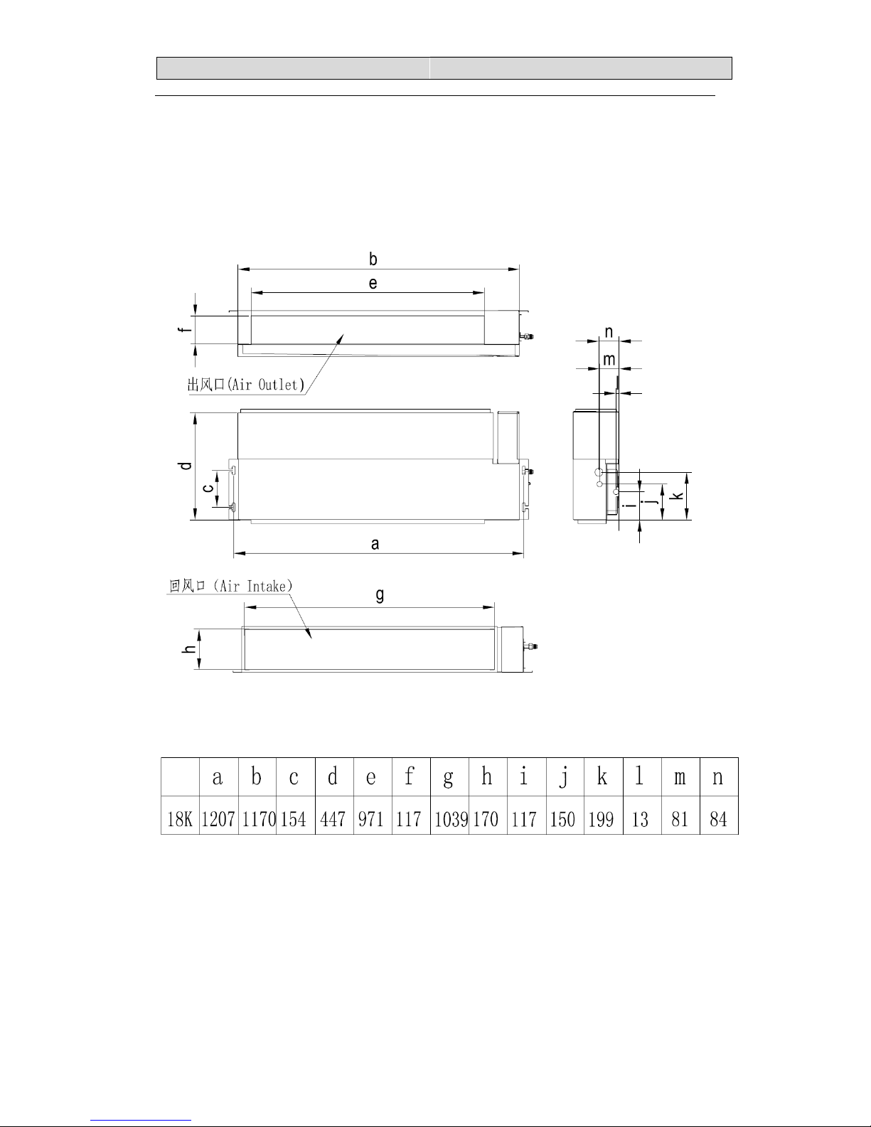
3.OUTLINES AND DIMENSIONS
3-1 INDOOR
Duct type
Page 27
33.. OOUUTTLLIINNEESS AANNDD DDIIMMEENNSSIIOONN
25
Page 28
33.. OOUUTTLLIINNEESS AANNDD DDIIMMEENNSSIIOONN
26
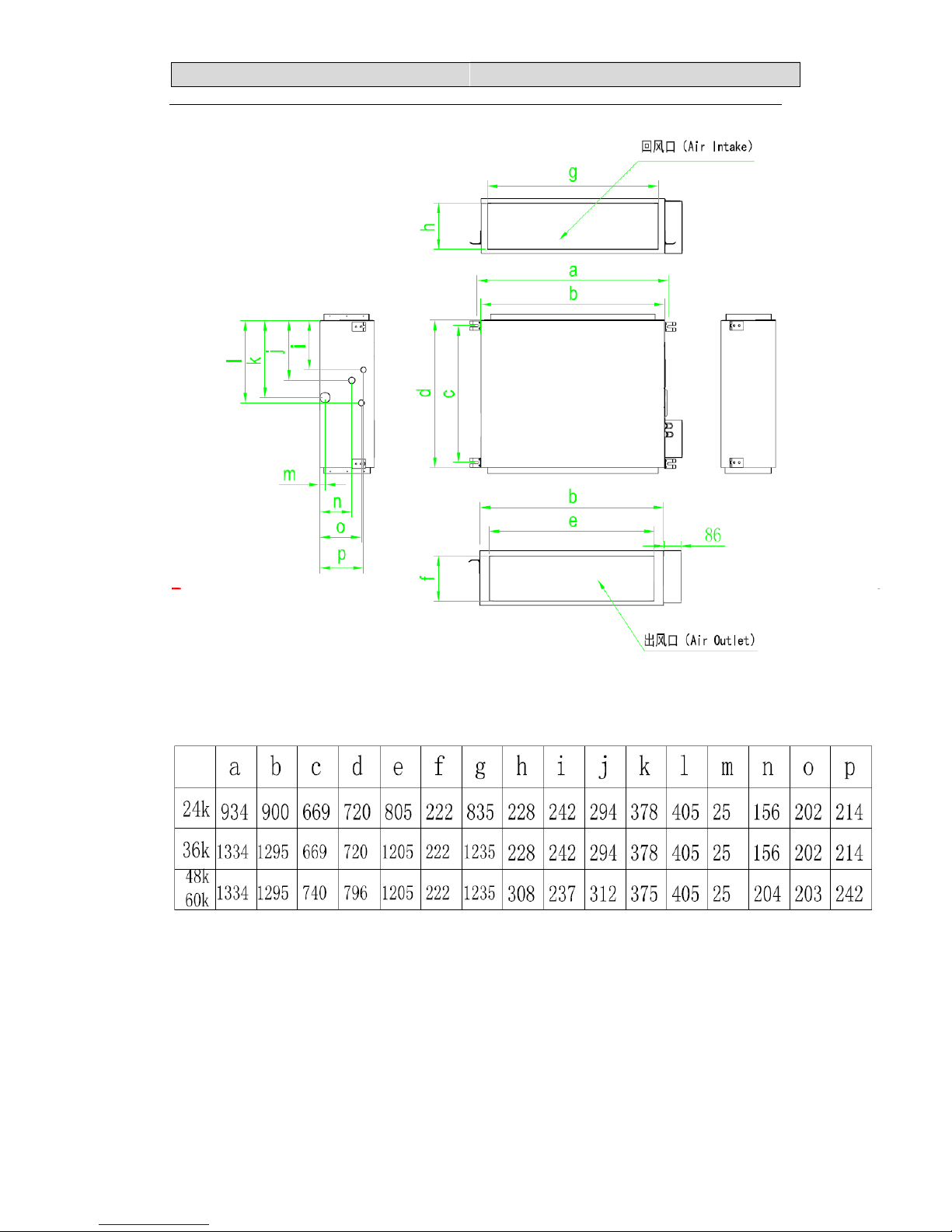
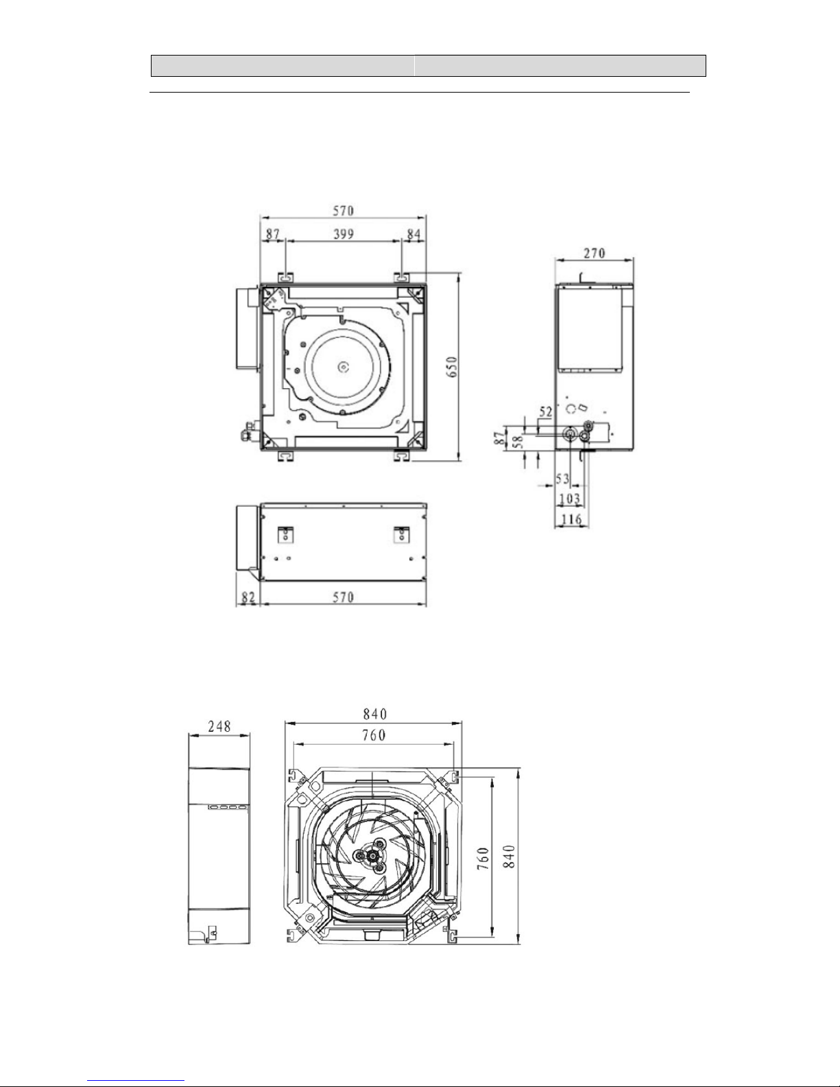
Cassette type
18K
24K,36K
Page 29
33.. OOUUTTLLIINNEESS AANNDD DDIIMMEENNSSIIOONN
27
48K,60K
Page 30
33.. OOUUTTLLIINNEESS AANNDD DDIIMMEENNSSIIOONN
28
Ceiling&Floor Type
Page 31

33.. OOUUTTLLIINNEESS AANNDD DDIIMMEENNSSIIOONN
29
3-2.OUTDOOR
18K(AUW-18U4SG)
Page 32

33.. OOUUTTLLIINNEESS AANNDD DDIIMMEENNSSIIOONN
30
18K(MODEL: AUW-18U4SZ1)
24K(MODEL: AUW-24U4SZ)
Page 33

33.. OOUUTTLLIINNEESS AANNDD DDIIMMEENNSSIIOONN
31
24&36K
(
MODEL: AUW-24U4SA1, AUW-36U4SA1, AUW-36W4SA)
Page 34

33.. OOUUTTLLIINNEESS AANNDD DDIIMMEENNSSIIOONN
32
48K&60K
(
MODEL: AUW-48U6SP、AUW-60U6SP)
Page 35

4 DIAGRAM&DATA
33
4. Diagrams&DATA
4.1 Piping Diagrams
18k type
Page 36

4 DIAGRAM&DATA
34
24k &36K type
Indoor heat exchanger
Indoor
Outdoor
Stop Valve
Coil
temperature
sensor
Accumulator
Ambient
temperature
sensor
Stop Valve
Discharge
temperature
sensor
Discharge
Pressure
Switch
4-Way Valve
Ambient
temperature
sensor
Coil
temperature
sensor
Outdoor
heat
exchanger
Compressor
strainer
strainer
Electronic expansion valve
Defrost
temperature
sensor
Suction
temperature
sensor
Page 37

4 DIAGRAM&DATA
35
48K&60K
Indoor heat exchanger
Indoor
Outdoor
Stop Valve
Coil
temperature
sensor
Accumulator
Ambient
temperature
sensor
Stop Valve
Discharge
temperature
sensor
Discharge
Pressure
Switch
4-Way Valve
Ambient
temperature
sensor
Coil
temperature
sensor
Outdoor
heat
exchanger
Suction
Pressure
Switch
Compressor
strainer
strainer
Electronic expansion valve
Defrost
temperature
sensor
Suction
temperature
sensor
Page 38

4 DIAGRAM&DATA
36
4-2MAX. Refrigerant pipe length and height difference
*Doyourbesttoreducethepipelength.Longpipemaycausecapacityoftheindoorunitincline.
Outdoorunitprecharged
Total refrigerantpipelength
0m~5m
5m~60m
AUW‐18U4SG 1270g 0g
Xg=15g/m × (Totalpipelength(m)‐5)
AUW‐24U4SZ 1500g 0g
AUW-36U4SA
2100g 0g
AUW-18U4SZ1
1400g 0g
AUW-24U4SA1
1680g 0g
Xg=35g/m × (Totalpipelength(m)‐5)
AUW-36U4SA1
2100g 0g
AUW-48U6SP
3000g 0g
AUW-60U6SP
3500g 0g
Page 39

4 DIAGRAM&DATA
37
4-3ELECTRIC Diagrams
Recommend Wire Size
Model POWER SUPPLY
Power Source
Cable Size
(mm2)
Transmitting Cable
Size
(mm2)
18K 220-240V,50Hz 3×1.5 4×0.75
24K/36K 220-240V,50Hz 3×2.5 4×0.75
48K/60K
380~415V,3N~,50Hz
5×2.5 4×0.75
● Use an ELB (Electric Leakage Breaker). If not used, it will cause an electric shock or a
fire.
● Do not operate the system until all the check points have been cleared.
(A) Check to ensure that the insulution resistance is more than 1 megohm, by measuring
the resistance between ground and the terminal of the electrical parts. If not, do not
operate the system until the electrical leakage is found and repaired.
Page 40

4 DIAGRAM&DATA
38
(B) Check to ensure that the stop valves of the outdoor unit are fully opened and then start
the system.
● Pay attention to the following items while the system is running.
(A) Do not touch any of the parts by hand at the discharge gas side, since the compressor
chamber and the pipes at the discharge side are heated higher than 90 .℃
(B) DO NOT PUSH THE BUTTON OF THE MAGNETIC SWITCH(ES). It will cause a
serious Accident.
NOTES:
1) Follow local codes and regulations when selecting field wires.
2) The wire sizes marked in the table are selected at the maxim current of the
unit according to the European Standard ,En60 335-1. Use the wires which are
not lighter than the ordinary tough rubber sheathed flexible cord (code
designation H07RN-F) or ordinary polychloroprene sheathed flexible
cord (code designation H07RN-F) .
3) Use a shielded cable for the transmitting circuit and connect it to ground .
4) In the case that power cables are connected in series, add each unit
maximum current and select wires below.
* in the case that current exceeds 63A, do not connect cables in series.
Page 41

4 DIAGRAM&DATA
39
4-4Air flow and ESP Chart Diagrams(for duct type)
18K
L
M
H
0
5
10
15
20
25
30
35
500 600 700 800 900 1000
ESP
Airflow(m3/h)
18KCurvefor10PaESP
10
15
20
25
30
35
40
45
50
500 600 700 800 900 1000 1100
ESP
Airflow(m3/h)
18KCurvefor30PaESP
Page 42

4 DIAGRAM&DATA
40
24K
L
M
H
10
20
30
40
50
60
70
80
90
700 800 900 1000 1100 1200 1300 1400
ESP
Airflow(m3/h)
24KCurvefor50PaESP
LM
H
40
50
60
70
80
90
100
110
120
130
600 700 800 900 1000 1100 1200 1300 1400 1500
ESP
Airflow(m3/h)
24KCurvefor80PaESP
Page 43

4 DIAGRAM&DATA
41
36K(ACMOTOR)
L
M
H
30
40
50
60
70
80
90
900 1100 1300 1500 1700 1900
ESP
Airflow(m3/h)
36KCurvefor50PaESP
L
M
H
50
60
70
80
90
100
110
120
130
800 1000 1200 1400 1600 1800 2000
ESP
Airflow(m3/h)
36KCurvefor80PaESP
Page 44

4 DIAGRAM&DATA
42
48K
L
MH
50
60
70
80
90
100
110
120
1500 1700 1900 2100 2300 2500
ESP
Airflow(m³/h)
48KCurvefor80PaESP
LMH
90
100
110
120
130
140
150
160
1500 1700 1900 2100 2300 2500
ESP
Airflow(m³/h)
48KCurvefor120PaESP
Page 45

4 DIAGRAM&DATA
43
60K
L
MH
50
60
70
80
90
100
110
120
1500 1700 1900 2100 2300 2500
ESP
Airflow(m³/h)
60KCurvefor80PaESP
LMH
90
100
110
120
130
140
150
160
1500 1700 1900 2100 2300 2500
ESP
Airflow(m³/h)
60KCurvefor120PaESP
Page 46

55.. EELLEECCTTRRIICCAALL DDAATTAA
44
5-1.Electrical wiring diagrams
INDOOR UNIT
Duct type
AUD-18UX4SKL,AUD-18UX4SKL1
Page 47

55.. EELLEECCTTRRIICCAALL DDAATTAA
45
AUD-24UX4SLH,AUD-36UX4SMH
Page 48

55.. EELLEECCTTRRIICCAALL DDAATTAA
46
AUD-24U4SLH1,AUD-36U4SMH1
Page 49

55.. EELLEECCTTRRIICCAALL DDAATTAA
47
AUD-48UX4SHH,AUD-60UX4SHH
Page 50

55.. EELLEECCTTRRIICCAALL DDAATTAA
48
Cassette type
18k
24K ,36K,48K,60K
Page 51

55.. EELLEECCTTRRIICCAALL DDAATTAA
49
Ceiling&Floor type
18K,48K,60K
24K,36K
Page 52

55.. EELLEECCTTRRIICCAALL DDAATTAA
50
OUTDOOR UNIT
18K
AUW-18U4SG
Page 53

55.. EELLEECCTTRRIICCAALL DDAATTAA
51
AUW-18U4SZ1
Page 54

55.. EELLEECCTTRRIICCAALL DDAATTAA
52
24K
AUW-24U4SZ
Page 55

55.. EELLEECCTTRRIICCAALL DDAATTAA
53
AUW-24U4SA1
Page 56

55.. EELLEECCTTRRIICCAALL DDAATTAA
54
36K
AUW-36U4SA
Page 57

55.. EELLEECCTTRRIICCAALL DDAATTAA
55
AUW-36U4SA1
Page 58

55.. EELLEECCTTRRIICCAALL DDAATTAA
56
AUW-48U6SP
AUW-60U6SP
Page 59

55.. EELLEECCTTRRIICCAALL DDAATTAA
57
5-2. Electric control Board
1. Indoor control board
Duct type
18K,48K,60K
&AUD-24UX4SLH, AUD-36UX4SMH
AUD-24UX4SLH1, AUD-36UX4SMH1
Page 60

55.. EELLEECCTTRRIICCAALL DDAATTAA
58
CASETTE Type
18K
24K,36K,48K,60K
Page 61

55.. EELLEECCTTRRIICCAALL DDAATTAA
59
Ceiling & Floor type
18k,48k,60k
24k,36k
Page 62

55.. EELLEECCTTRRIICCAALL DDAATTAA
60
2.Control board for outdoor unit
1) OUTDOOR CONTROL BOARD
AUW-18U4SG
1) CONTROL BOARD(AUW-18U4SG)
CONTROL BOARD(AUW-24U4SZ)
Page 63

55.. EELLEECCTTRRIICCAALL DDAATTAA
61
CONTROL BOARD(AUW-36U4SA)
AC N IN
AC L IN
Communication SI
Communication N
High pressure switch
Liquid and Gas Sensor
Outdoor/suction/coil Sensor
Discharge Sensor
Electric expansion valve
Overload protection switch
DC+
DC-
IPM power
IPM-SI
4-way valve
AC fan motor N OUT Heater N Earth
Heater L
Page 64

55.. EELLEECCTTRRIICCAALL DDAATTAA
62
CONTROL BOARD(AUW-48U6SP、AUW-60U6SP)
AC N IN
AC L IN
AC L OUT
Communication SI
Communication N
Discharge Sensor
Suction Sensor
coil/defrost Sensor
Outdoor Sensor
High pressure switch
Low pressure switch
DC+
DC-
4-way valve
AC fan motor
Heater N
Earth
4-way valve
N OUT
Heater L
Electric expansion valve
IPM power
IPM-SI
Heater N
POWER IN
Transformer
Down fan motor
Up fan motor
Page 65

55.. EELLEECCTTRRIICCAALL DDAATTAA
63
(AUW-18U4SZ1,AUW-24U4SA1、AUW-36U4SA1)
Page 66

55.. EELLEECCTTRRIICCAALL DDAATTAA
64
IPM Board
IPM Board(AUW-18U4SG)
AC N IN
AC L IN
AC L OUT
Communication SI
Communication N
Discharge Sensor
Suction Sensor
coil/defrost Sensor
Outdoor Sensor
High pressure switch
Low pressure switch
DC+
DC-
4-way valve
Heater N
Earth
N OUT
Heater L
Electric expansion valve
IPM power
IPM-SI
Page 67

55.. EELLEECCTTRRIICCAALL DDAATTAA
65
To Compressor U
To Compressor V
To Compresso r W
To Electrolytic
Capacitor +
To Electroly tic
Capacitor +
To Main Control
Board
IPM Pow e r
To Electrolytic
Capacitor -
To PFC Induc tor-2
To PFC Inductor-1
AC N IN
AC L IN
(AUW-24U4SZ / AUW-36U4SA)
To M a in C o ntrol
Board
To Compressor U
To Compressor V
To Compressor W
IPM Pow e r
To Ele ctr o lytic
Capac itor -
To Electrolytic
Capacitor +
To Electrolytic
Capacitor +
To PFC
Inductor-2
To PFC
Inductor-1
ac N in
ac L in
(AUW-18U4SZ1、AUW-24U4SA1、AUW-36U4SA1)
Page 68

55.. EELLEECCTTRRIICCAALL DDAATTAA
66
(AUW-48U6SP、AUW-60U6SP)
-
-
-
-
Page 69

55.. EELLEECCTTRRIICCAALL DDAATTAA
67
5-3. DIP SWITCH SETTING OF OUTDOOR
AUW-18U4SZ1,AUW-24U4SA1,AUW-36U4SA1,AUW-36W4SA
48K&60K
Page 70

55.. EELLEECCTTRRIICCAALL DDAATTAA
68
5-4. Digital Display Switch of Outdoor
Digital Display Switch Introduction
It can be used to check outdoor running parameters.
There are 3 buttons on the digital display board:
1)SWITH button:Indoor parameters and outdoor parameters can be select in turn by press it.
P--outdoor unit,H--indoor unit;
2)INCREASE button:Each time it is pressed,the number rises by 1,hold down it,the number will be
rapidly rises;
3)DECREASE button:Each time it is pressed,the number lowers by 1,hold down it,the number will be
Page 71

55.. EELLEECCTTRRIICCAALL DDAATTAA
69
rapidly lowers.
Parameters can be checked as following table below.
Parameter
code
Descriptions
0 Protect Code or Error Code
P.1 Target Frequency
P.2 Driver Frequency
P.4 Outdoor Electronic expansion valve Opening
P.5 Outdoor Electronic expansion valve Target Opening
P.6 Upper DC Motor Revolving Speed
P.8 AC Input Voltage
P.9 Current
P.10 Modular Temperature
P.11 Capacity needed
P.12 Modular Trouble
P.20 Outdoor Ambient Temperature
P.21 Outdoor Coil Temperature
P.22 Outdoor Defrost Temperature
P.23 Suction Temperature
P.24 Discharge Temperature
H.1 Indoor Unit Error
H.2 Indoor Ambient Temperature
H.3 Indoor Coil Temperature
H.4 Indoor Setting Temperature
Page 72

55.. EELLEECCTTRRIICCAALL DDAATTAA
70
5-5. Static Pressure Setting(only for duct type)
CHANGE OF STATIC PRESSURE
The static pressure outside the indoor unit can be chosen .
Models except AUD-24UX4SALH1 & AUD-36UX4SAMH1 :
You can change the static pressure by changing the fan motor terminal which refer to following
Fig.below:
AUD-24UX4SALH1 & AUD-36UX4SAMH1 :
Default static pressure is 30 Pa.
The static pressure can be freely adjusted from 1 Pa to 80 Pa by using specific wire remote
controller(YXE-C01U).
Operation details, please refer to wire remote controller manuals .
If you still have any trouble, please contact local technical service center of our company for
further information.
Page 73

55.. EELLEECCTTRRIICCAALL DDAATTAA
71
Page 74

55.. EELLEECCTTRRIICCAALL DDAATTAA
72
5-6.AMBIENT TEMPERATURE REVISE(INDOOR)
when indoor unit highly mounted,because of hot air floatation,cold air sinks,so the ambient
temperature sensed by indoor unit is higher than the actual.Then the ambient temperature need
to be revised.
It can be changed by using specific wire remote controller(YXE-C01U).
Operation details, please refer to wire remote controller manuals .
Page 75

55.. EELLEECCTTRRIICCAALL DDAATTAA
73
5-7. Sensor parameter
1. THE PARAMETER OF OUTDOOR COMPRESSOR DISCHARGE TEMPERATURE SENSOR:
(R
0
=187.25K±6.3%;R
100
=3.77K±2.5K;B0/100=3979K±1%)
T [ ℃ ] Rmin [ KΩ ] Rnom [ KΩ ] Rmax [ KΩ ]
DR(MIN)% DR(MAX)%
-30 908.2603 985.5274 1065.1210 -7.84 7.47
-29 855.3955 927.6043 1001.9150 -7.78 7.42
-28 805.9244 873.4324 924.8368 -7.73 5.56
-27 759.6097 822.7471 887.5944 -7.67 7.31
-26 716.2320 775.3041 835.9165 -7.62 7.25
-25 675.5881 730.8775 787.5529 -7.56 7.20
-24 637.4902 689.2583 742.2720 -7.51 7.14
-23 601.7645 650.2533 699.8601 -7.46 7.09
-22 568.2499 613.6835 660.1191 -7.40 7.03
-21 536.7970 579.3832 622.8658 -7.35 6.98
-20 507.2676 547.1989 587.9307 -7.30 6.93
-19 497.5332 516.9882 555.1565 -3.76 6.88
-18 453.4748 488.6192 524.3977 -7.19 6.82
-17 428.9819 461.9693 495.5191 -7.14 6.77
-16 405.9517 436.9251 486.3954 -7.09 10.17
-15 384.2888 413.3808 442.9105 -7.04 6.67
-14 363.9047 391.2386 418.9563 -6.99 6.62
-13 344.7169 370.4072 396.4325 -6.94 6.56
-12 326.6497 350.8019 375.2461 -6.88 6.51
-11 309.6286 332.3441 355.3104 -6.83 6.46
-10 293.5903 314.9620 336.5448 -6.79 6.41
-9 278.4719 298.5822 318.3744 -6.74 6.22
-8 264.2156 283.1464 302.2294 -6.69 6.31
-7 250.7678 268.5936 286.5448 -6.64 6.26
-6 238.0783 254.8686 271.7603 -6.59 6.22
-5 226.1003 241.9200 257.8193 -6.54 6.17
-4 214.7903 229.6997 244.6593 -6.49 6.11
-3 204.1073 218.1630 232.2612 -6.44 6.07
-2 194.0135 207.2681 220.5495 -6.39 6.02
-1 184.4732 196.9759 209.4913 -6.35 5.97
0 175.4533 187.2500 199.0468 -6.30 5.93
1 166.8952 178.0255 189.1529 -6.25 5.88
2 158.8023 169.3067 179.8058 -6.20 5.84
3 151.1467 161.0633 170.9724 -6.16 5.80
4 143.9026 153.2667 162.6216 -6.11 5.75
5 137.0455 145.8905 154.7246 -6.06 5.71
6 130.5528 138.9097 147.2544 -6.02 5.67
7 124.4033 132.3011 140.1856 -5.97 5.62
8 118.5769 126.0429 133.4946 -5.92 5.58
9 113.0550 120.1146 127.1591 -5.88 5.54
Page 76

55.. EELLEECCTTRRIICCAALL DDAATTAA
74
T [ ℃ ] Rmin [ KΩ ] Rnom [ KΩ ] Rmax [ KΩ ]
DR(MIN)% DR(MAX)%
10 107.8202 114.4973 121.1586 -5.83 5.50
11 102.8560 109.1728 115.4734 -5.79 5.46
12 98.1470 104.1246 110.0855 -5.74 5.41
13 93.6787 99.3367 104.9778 -5.70 5.37
14 89.4378 94.7946 100.1342 -5.65 5.33
15 85.4114 90.4842 95.5398 -5.61 5.29
16 81.5875 86.3926 91.1805 -5.56 5.25
17 77.9551 82.5076 87.0430 -5.52 5.21
18 74.5034 78.8177 83.1150 -5.47 5.17
19 71.2227 75.3122 79.3848 -5.43 5.13
20 68.1036 71.9808 75.8414 -5.39 5.09
21 65.1373 68.8141 72.4746 -5.34 5.05
22 62.3155 65.8032 69.2746 -5.30 5.01
23 59.6306 62.9395 66.2324 -5.26 4.97
24 57.0752 60.2152 63.3395 -5.21 4.93
25 54.6424 57.6227 60.5877 -5.17 4.89
26 52.3258 55.1551 57.9695 -5.13 4.85
27 50.1192 52.8058 55.4778 -5.09 4.82
28 48.0168 50.5684 53.1058 -5.05 4.78
29 46.0133 48.4371 50.8472 -5.00 4.74
30 44.1034 46.4046 48.6960 -4.96 4.71
31 42.2825 44.4711 46.6466 -4.92 4.66
32 40.5458 42.6261 44.6937 -4.88 4.63
33 38.8891 40.8668 42.8323 -4.84 4.59
34 37.3084 39.1890 41.0576 -4.80 4.55
35 35.7998 37.5883 39.3653 -4.76 4.51
36 34.3596 36.0609 37.7511 -4.72 4.48
37 32.9844 34.6030 36.2109 -4.68 4.44
38 31.6710 33.2113 34.7412 -4.64 4.40
39 30.4164 31.8823 33.3383 -4.60 4.37
40 29.2176 30.6130 31.9988 -4.56 4.33
41 28.0718 29.4004 30.7197 -4.52 4.29
42 26.9765 28.2417 29.4979 -4.48 4.26
43 25.9293 27.1342 28.3306 -4.44 4.22
44 24.9277 26.0755 27.2150 -4.40 4.19
45 23.9697 25.0632 26.1488 -4.36 4.15
46 23.0530 24.0950 25.1293 -4.32 4.12
47 22.1757 23.1688 24.1545 -4.29 4.08
48 21.3360 22.2826 23.2221 -4.25 4.05
49 20.5321 21.4345 22.3301 -4.21 4.01
50 19.7623 20.6226 21.4766 -4.17 3.98
51 19.0261 19.8468 20.6612 -4.14 3.94
52 18.3211 19.1040 19.8808 -4.10 3.91
Page 77

55.. EELLEECCTTRRIICCAALL DDAATTAA
75
T [ ℃ ] Rmin [ KΩ ] Rnom [ KΩ ] Rmax [ KΩ ]
DR(MIN)% DR(MAX)%
53 17.6458 18.3926 19.1338 -4.06 3.87
54 16.9986 17.7113 18.4185 -4.02 3.84
55 16.3784 17.0537 17.7335 -3.96 3.83
56 15.7839 16.4332 17.0774 -3.95 3.77
57 15.2139 15.8338 16.4488 -3.92 3.74
58 14.6673 15.2592 15.8464 -3.88 3.71
59 14.1430 14.7083 15.2690 -3.84 3.67
60 13.6400 14.1799 14.7154 -3.81 3.64
61 13.1573 13.6730 14.1846 -3.77 3.61
62 12.6941 13.1868 13.6756 -3.74 3.57
63 12.2494 12.7202 13.1872 -3.70 3.54
64 11.8224 12.2723 12.7186 -3.67 3.51
65 11.4124 11.8424 12.2690 -3.63 3.48
66 11.0185 11.4295 11.8373 -3.60 3.45
67 10.6401 11.0331 11.4230 -3.56 3.41
68 10.2765 10.6522 11.0251 -3.53 3.38
69 9.9271 10.2863 10.6429 -3.49 3.35
70 9.5912 9.9348 10.2756 -3.46 3.32
71 9.2682 9.5968 9.9231 -3.42 3.29
72 8.9576 9.2720 9.5841 -3.39 3.26
73 8.6589 8.9597 9.2583 -3.36 3.23
74 8.3716 8.6594 8.9451 -3.32 3.19
75 8.0951 8.3705 8.6440 -3.29 3.16
76 7.8290 8.0926 8.3544 -3.26 3.13
77 7.5730 7.8252 8.0758 -3.22 3.10
78 7.3264 7.5679 7.8078 -3.19 3.07
79 7.0891 7.3202 7.5499 -3.16 3.04
80 6.8605 7.0818 7.3018 -3.12 3.01
81 6.6403 6.8522 7.0629 -3.09 2.98
82 6.4282 6.6311 6.8329 -3.06 2.95
83 6.2239 6.4182 6.6115 -3.03 2.92
84 6.0269 6.2131 6.3982 -3.00 2.89
85 5.8371 6.0154 6.1928 -2.96 2.86
86 5.6542 5.8249 5.9949 -2.93 2.84
87 5.4777 5.6413 5.8042 -2.90 2.81
88 5.3076 5.4644 5.6205 -2.87 2.78
89 5.1435 5.2937 5.4433 -2.84 2.75
90 4.9853 5.1292 5.2726 -2.81 2.72
91 4.8326 4.9705 5.1079 -2.77 2.69
92 4.6852 4.8174 4.9492 -2.74 2.66
93 4.5430 4.6697 4.7960 -2.71 2.63
94 4.4058 4.5272 4.6483 -2.68 2.61
95 4.2733 4.3896 4.5058 -2.65 2.58
Page 78

55.. EELLEECCTTRRIICCAALL DDAATTAA
76
T [ ℃ ] Rmin [ KΩ ] Rnom [ KΩ ] Rmax [ KΩ ]
DR(MIN)% DR(MAX)%
96 4.1453 4.2568 4.3683 -2.62 2.55
97 4.0218 4.1287 4.2355 -2.59 2.52
98 3.9024 4.0049 4.1074 -2.56 2.50
99 3.7872 3.8854 3.9837 -2.53 2.47
100 3.6758 3.7700 3.8643 -2.50 2.44
101 3.5661 3.6585 3.7512 -2.53 2.47
102 3.4601 3.5509 3.6419 -2.56 2.50
103 3.3577 3.4468 3.5362 -2.59 2.53
104 3.2588 3.3463 3.4341 -2.61 2.56
105 3.1632 3.2491 3.3353 -2.64 2.58
106 3.0708 3.1551 3.2398 -2.67 2.61
107 2.9816 3.0643 3.1475 -2.70 2.64
108 2.8953 2.9765 3.0582 -2.73 2.67
109 2.8118 2.8915 2.9717 -2.76 2.70
110 2.7311 2.8093 2.8881 -2.78 2.73
111 2.6531 2.7299 2.8072 -2.81 2.75
112 2.5776 2.6530 2.7289 -2.84 2.78
113 2.5046 2.5785 2.6531 -2.87 2.81
114 2.4340 2.5065 2.5798 -2.89 2.84
115 2.3656 2.4368 2.5087 -2.92 2.87
116 2.2995 2.3693 2.4400 -2.95 2.90
117 2.2354 2.3040 2.3733 -2.98 2.92
118 2.1734 2.2407 2.3088 -3.00 2.95
119 2.1134 2.1795 2.2463 -3.03 2.97
120 2.0553 2.1201 2.1858 -3.06 3.01
121 1.9991 2.0626 2.1271 -3.08 3.03
122 1.9446 2.0070 2.0702 -3.11 3.05
123 1.8918 1.9530 2.0151 -3.13 3.08
124 1.8406 1.9007 1.9617 -3.16 3.11
125 1.7911 1.8500 1.9099 -3.18 3.14
126 1.7430 1.8009 1.8597 -3.22 3.16
127 1.6965 1.7533 1.8110 -3.24 3.19
128 1.6514 1.7071 1.7638 -3.26 3.21
129 1.6076 1.6623 1.7180 -3.29 3.24
130 1.5652 1.6189 1.6736 -3.32 3.27
Page 79

55.. EELLEECCTTRRIICCAALL DDAATTAA
77
2. THE PARAMETER OF THE OTHER SENSOR IN INDOOR AND OUTDOOR UNIT:(R0=15K±2%;
B0/100=3450K±2%)
T [℃] Rmin [ KΩ ] Rnom [ KΩ ] Rmax [ KΩ ]
DR(MIN)% DR(MAX)%
-30 60.78 64.77 68.99 -6.16 6.12
-29 57.75 61.36 65.16 -5.88 5.83
-28 54.89 58.15 61.58 -5.61 5.57
-27 52.19 55.14 58.23 -5.35 5.31
-26 49.63 52.30 55.08 -5.11 5.05
-25 47.21 49.62 52.13 -4.86 4.81
-24 44.92 47.10 49.37 -4.63 4.60
-23 42.76 44.73 46.78 -4.40 4.38
-22 40.71 42.49 44.34 -4.19 4.17
-21 38.77 40.38 42.05 -3.99 3.97
-20 36.93 38.39 39.90 -3.80 3.78
-19 35.18 36.51 37.87 -3.64 3.59
-18 33.53 34.74 35.97 -3.48 3.42
-17 31.96 33.06 34.17 -3.33 3.25
-16 30.48 31.47 32.49 -3.15 3.14
-15 29.07 29.97 30.89 -3.00 2.98
-14 27.73 28.56 29.39 -2.91 2.82
-13 26.46 27.22 27.98 -2.79 2.72
-12 25.26 25.95 26.64 -2.66 2.59
-11 24.11 24.75 25.38 -2.59 2.48
-10 23.03 23.61 24.19 -2.46 2.40
-9 21.99 22.53 23.06 -2.40 2.30
-8 21.01 21.51 22.00 -2.32 2.23
-7 20.08 20.54 20.99 -2.24 2.14
-6 19.19 19.62 20.04 -2.19 2.10
-5 18.35 18.74 19.14 -2.08 2.09
-4 17.55 17.92 18.29 -2.06 2.02
-3 16.78 17.13 17.48 -2.04 2.00
-2 16.06 16.38 16.71 -1.95 1.97
-1 15.36 15.67 15.98 -1.98 1.94
0 14.70 15.00 15.29 -2.00 1.90
1 14.08 14.36 14.64 -1.95 1.91
2 13.48 13.75 14.02 -1.96 1.93
3 12.91 13.17 13.43 -1.97 1.94
4 12.36 12.62 12.87 -2.06 1.94
5 11.85 12.09 12.34 -1.99 2.03
6 11.35 11.59 11.83 -2.07 2.03
7 10.88 11.11 11.35 -2.07 2.11
8 10.43 10.66 10.89 -2.16 2.11
9 9.999 10.230 10.450 -2.26 2.11
10 9.590 9.816 10.040 -2.30 2.23
Page 80

55.. EELLEECCTTRRIICCAALL DDAATTAA
78
T [℃] Rmin [ KΩ ] Rnom [ KΩ ] Rmax [ KΩ ]
DR(MIN)% DR(MAX)%
11 9.199 9.422 9.647 -2.37 2.33
12 8.826 9.047 9.269 -2.44 2.40
13 8.470 8.689 8.910 -2.52 2.48
14 8.129 8.347 8.567 -2.61 2.57
15 7.804 8.021 8.240 -2.71 2.66
16 7.493 7.709 7.928 -2.80 2.76
17 7.196 7.412 7.630 -2.91 2.86
18 6.912 7.127 7.346 -3.02 2.98
19 6.640 6.855 7.074 -3.14 3.10
20 6.381 6.595 6.815 -3.24 3.23
21 6.132 6.347 6.567 -3.39 3.35
22 5.894 6.109 6.330 -3.52 3.49
23 5.667 5.882 6.103 -3.66 3.62
24 5.449 5.664 5.886 -3.80 3.77
25 5.240 5.456 5.678 -3.96 3.91
26 5.048 5.260 5.478 -4.03 3.98
27 4.864 5.072 5.286 -4.10 4.05
28 4.687 4.891 5.101 -4.17 4.12
29 4.517 4.717 4.924 -4.24 4.20
30 4.355 4.550 4.753 -4.29 4.27
31 4.198 4.390 4.589 -4.37 4.34
32 4.048 4.236 4.431 -4.44 4.40
33 3.904 4.089 4.280 -4.52 4.46
34 3.766 3.946 4.134 -4.56 4.55
35 3.663 3.810 3.994 -3.86 4.61
36 3.506 3.679 3.859 -4.70 4.66
37 3.383 3.552 3.729 -4.76 4.75
38 3.265 3.431 3.604 -4.84 4.80
39 3.152 3.314 3.484 -4.89 4.88
40 3.043 3.202 3.368 -4.97 4.93
41 2.938 3.094 3.257 -5.04 5.00
42 2.838 2.990 3.149 -5.08 5.05
43 2.741 2.890 3.046 -5.16 5.12
44 2.648 2.793 2.946 -5.19 5.19
45 2.558 2.701 2.850 -5.29 5.23
46 2.472 2.611 2.758 -5.32 5.33
47 2.389 2.525 2.669 -5.39 5.40
48 2.309 2.443 2.583 -5.49 5.42
49 2.232 2.363 2.500 -5.54 5.48
50 2.158 2.286 2.421 -5.60 5.58
51 2.087 2.212 2.344 -5.65 5.63
52 2.018 2.140 2.269 -5.70 5.69
53 1.952 2.072 2.198 -5.79 5.73
Page 81

55.. EELLEECCTTRRIICCAALL DDAATTAA
79
T [℃] Rmin [ KΩ ] Rnom [ KΩ ] Rmax [ KΩ ]
DR(MIN)% DR(MAX)%
54 1.888 2.005 2.129 -5.84 5.82
55 1.827 1.941 2.062 -5.87 5.87
56 1.767 1.880 1.998 -6.01 5.91
57 1.710 1.820 1.936 -6.04 5.99
58 1.655 1.763 1.876 -6.13 6.02
59 1.602 1.707 1.818 -6.15 6.11
60 1.551 1.654 1.762 -6.23 6.13
61 1.502 1.602 1.709 -6.24 6.26
62 1.452 1.553 1.657 -6.50 6.28
63 1.409 1.505 1.606 -6.38 6.29
64 1.364 1.458 1.558 -6.45 6.42
65 1.322 1.413 1.511 -6.44 6.49
66 1.280 1.370 1.466 -6.57 6.55
67 1.241 1.328 1.422 -6.55 6.61
68 1.202 1.288 1.379 -6.68 6.60
69 1.165 1.249 1.339 -6.73 6.72
70 1.129 1.211 1.299 -6.77 6.77
71 1.095 1.175 1.261 -6.81 6.82
72 1.061 1.140 1.224 -6.93 6.86
73 1.029 1.106 1.188 -6.96 6.90
74 0.9977 1.073 1.153 -7.02 6.94
75 0.9676 1.041 1.120 -7.05 7.05
76 0.9385 1.011 1.088 -7.17 7.08
77 0.9104 0.9810 1.056 -7.20 7.10
78 0.8833 0.9523 1.026 -7.25 7.18
79 0.8570 0.9246 0.9971 -7.31 7.27
80 0.8316 0.8977 0.9687 -7.36 7.33
81 0.8071 0.8717 0.9412 -7.41 7.38
82 0.7834 0.8466 0.9146 -7.47 7.43
83 0.7604 0.8223 0.8888 -7.53 7.48
84 0.7382 0.7987 0.8639 -7.57 7.55
85 0.7167 0.7759 0.8397 -7.63 7.60
86 0.6958 0.7537 0.8161 -7.68 7.65
87 0.6755 0.7322 0.7933 -7.74 7.70
88 0.6560 0.7114 0.7712 -7.79 7.75
89 0.6371 0.6913 0.7498 -7.84 7.80
90 0.6188 0.6718 0.7291 -7.89 7.86
91 0.6011 0.6530 0.7051 -7.95 7.39
92 0.5840 0.6348 0.6897 -8.00 7.96
93 0.5674 0.6171 0.6709 -8.05 8.02
94 0.5514 0.6000 0.6527 -8.10 8.07
95 0.5359 0.5835 0.6350 -8.16 8.11
96 0.5209 0.5675 0.6179 -8.21 8.16
Page 82

55.. EELLEECCTTRRIICCAALL DDAATTAA
80
T [℃] Rmin [ KΩ ] Rnom [ KΩ ] Rmax [ KΩ ]
DR(MIN)% DR(MAX)%
97 0.5064 0.5519 0.6014 -8.24 8.23
98 0.4923 0.5369 0.5853 -8.31 8.27
99 0.4787 0.5224 0.5698 -8.37 8.32
100 0.4655 0.5083 0.5547 -8.42 8.36
101 0.4528 0.4946 0.5401 -8.45 8.42
102 0.4404 0.4814 0.5259 -8.52 8.46
103 0.4284 0.4685 0.5121 -8.56 8.51
104 0.4168 0.4561 0.4988 -8.62 8.56
105 0.4056 0.4440 0.4859 -8.65 8.62
106 0.3947 0.4323 0.4733 -8.70 8.66
107 0.3841 0.4210 0.4611 -8.76 8.70
108 0.3739 0.4100 0.4493 -8.80 8.75
109 0.3640 0.3993 0.4379 -8.84 8.81
110 0.3544 0.3890 0.4267 -8.89 8.84
111 0.3450 0.3789 0.4159 -8.95 8.90
112 0.3360 0.3692 0.4055 -8.99 8.95
113 0.3272 0.3597 0.3953 -9.04 9.01
114 0.3187 0.3505 0.3854 -9.07 9.06
115 0.3104 0.3416 0.3758 -9.13 9.10
116 0.3024 0.3330 0.3665 -9.19 9.14
117 0.2947 0.3246 0.3574 -9.21 9.18
118 0.2871 0.3164 0.3468 -9.26 8.77
119 0.2798 0.3085 0.3401 -9.30 9.29
120 0.2727 0.3008 0.33 -9.34 9.34
Page 83

66.. CCOONNTTRROOLL MMOODDEEL
L
80
6-1 Indoor control mode
1.Major general technical parameters
1 Conditionings for operation: Ambient temperatures: (-15 - +45 ℃),
relative humidity (45 - 85%).
2 Remote receiver distance: 8 m.
3 Remote receiver angle: Less than 80 degrees.
4 Temperature control accuracy: ±1℃.
5 Time error: Less than 1%.
6 The power supply for the air conditioner :
18k&24k&36K:
a.c 220V~240V, 50Hz, with its fluctuation in the range of (198V – 253 V).
48K&60K:
AC 380V-415V 3N~/50Hz, with its fluctuation in the range of (305V-438V).
2. Functions of the controller
Control function
3.1 Emergency switch
Press the emergency button can realize the starting or closing Machine, starting up
according to the automatic mode of operation.
3.2 Operator-machine communication
Air conditioning and remote controller is provided with a temperature sensor. The
remote controller on the temperature sensor to detect the default settings of room
temperature at room temperature. If the indoor control unit for long time have not received
remote control signal, will automatically switch to the air conditioner body temperature
sensor.
3.3 Timer function
1. Timer on: When set to start in a time by the remote controller, the air conditioner starts
in the timer on condition. When the set time is up, the air conditioner will turn on and
operates in the preset conditions after receiving a signal from the remote controller. If the air
Page 84

66.. CCOONNTTRROOLL MMOODDEEL
L
81
conditioner has not received a signal from the remote controller when the set time is up, it
will automatically start and operate in the preset conditions.
2. Timer off: When set to stop in a set time by the remote controller, the air conditioner
will start in the timer off condition. When the set time is up, the air conditioner will turn off
after receiving a signal from the remote controller. If the air conditioner has not received a
signal from the remote controller when the set time is up, it will turn off automatically.
3. Neither the turning on nor turning off operation will cancel the timer function。
3.4 Sleep
1. In the heating, cooling or dehumidifying mode, press the “Sleep” button on the remote
controller to start or cancel the sleep function in turn, and at the same time the sleep icon on
the display screen will be on or off accordingly.
2. In the heating mode, the set temperature will decrease automatically after the sleep
function is started.
3. In the cooling mode, the set temperature will rise automatically after the sleep function
is started.
4. In default, the setting is to cancel the sleep function. Turning off the unit will also
cancel the sleep function.
3.5 High efficient run function
In Cool, Dehumidification, Fan mode, press the "SUPER " to enter the refrigeration mode,
set the temperature automatically adjust to 18℃; the Fan speed is powerful speed;
frequency of high frequency operation.
In the heating mode, powerful function is invalid for H1 wireless remote controller.
3.6 mute function (only for H1 wireless remote controller)
In the indoor machine operation mode,You may turn on mute function and turn off mute
function by mute key, The air conditioner will run by mute fan speed in mute mode
3.7 prevent cooling wind mode
Page 85

66.. CCOONNTTRROOLL MMOODDEEL
L
82
In the heating-run, to prevent the indoor fan from blowing cold air, the indoor fan will stop
or run slowly until the coil is warmth.
3.8 blow waste heating and waste cooling function
The heating mode, remote shutdown, such as indoor heat exchanger temperature is
higher, the wind blowing out opportunities continue to run the waste heat.
Cool and dehumidification mode , after the compressor close, indoor machine will
continue to set the speed of operation for a period of time.
3.9 automatically model
This model does not automatically model function, emergency button cannot set the
automatic mode of operation, can use the emergency switch shutdown, remote setting the
automatic mode of indoor machine with remote signal.
3.10 Dehumidifying method:
Remote control setting dehumidifying mode, indoor machine forced to run at low
speed(high power key or a strong bond also maintain a low wind speed), the outdoor
machine according to the refrigeration mode operation.
3.11 Fault display
If the product operation failure, outdoor and indoor display control panel lights will quote
fault.
Page 86

66.. CCOONNTTRROOLL MMOODDEEL
L
83
6-2 Outdoor mode control
Summarization
1.1
18k、24k、36K
1. Voltage scale: 176V~253V,50Hz
2. Storage temperature scale: -40℃~85℃
3. Storage humidity scale: PH30%~PH95%
4. Working temperature:-20℃~85℃
5. accuracy for temperature control: ±0.5℃
1.2
48 k、60k
1. Voltage scale: 305V~438V,50Hz
2. Storage temperature scale: -40℃~85℃
3. Storage humidity scale: PH30%~PH95%
4. Working temperature:-20℃~85℃
5. accuracy for temperature control: ±0.5℃
2.Control function
Page 87

66.. CCOONNTTRROOLL MMOODDEEL
L
84
2.1Cooling Anti-freeze Protection
To prevent indoor air conditioner evaporator temperature is too low, the indoor coil
sensor for real time detection of evaporator. If the indoor coil temperature is too low, the
compressor will protect.
2.2 Overload Protection
Air can heat exchanger temperature sensor for monitoring, when the sensor when
the temperature is too high, the compressor will be automatic protection
2.3 Exhaust temperature protection
To prevent deterioration due to high exhaust temperature of compressor, the
machine will realize the real-time detection of the temperature of exhaust gas. If the
temperature is too high compressor automatic protection
2.4 Oil-return Control
When the compressor runs for a long time low frequencies, control system will start
the return oil program. The system in the oil return to the compressor.
2.5Operation Mode
Air conditioning mode is the operation mode set by users through remote controller,
four modes are available: cooling, heating, dehumidification, as well as fan mode.
2.6 Four-way Valve Control
Four-way valve of the outdoor machine shuts down when cooling and defrosting
but starts when heating. During the heating process, the four way valve to stop working for a
period of time after compressor disconnect.
2.7 Start-up Protection:
Page 88

66.. CCOONNTTRROOLL MMOODDEEL
L
85
To prevent compressor from restart frequently in the condition that system
pressure has not been completely balanced, it can’t be restarted within 3 minutes.
2.8 Pressure Protection:
When the pressure increases to a preset value, the pressure switch will
automatically protect. Compressor will stop and report the fault code protection.
Page 89

77.. TTRROOUUBBLLEE SSHHOOOOTTIINNGG
86
7-1- Error code
When the air conditioner failure occurs, the fault code will displays on outdoor control
board , wire remote controller or display panel.
1. INDOOR UNINT FAULT CODE DISPLAY
WALL MOUNTED TYPE
Run the air-conditioner by wireless remote controller , continue pressing
the“SLEEP ”button for 4 times, fault codes will flashing rapidly on the LCD . If no fault ,"00"
will display.
“ER”shows indoor display panel Communication fault with indoor unit control board .
FLOOR STANDING TYPE
In the case of no button-locked,continue pressing “CLOCK”button for 8 times ,fault
codes will display on the LCD for 10 seconds,automatically disappears after 10seconds.
Continue pressing “SLEEP”button of wireless remote controller for 8 times ,fault codes
will display on the LCD for 10 seconds,automatically disappears after 10seconds.
Check indoor unit control board---FAILURE LAMP
LED3 and LED2 indicates fault codes: LED2 indicate ten fault code, LED3 indicate bits
fault code (as shown fig. below).
“ER”shows indoor display panel Communication fault with indoor unit control board
LED2 and LED3 are failure indicate
lamps,
LED2 indicate fault code ten digit
number, LED3 indicate single digit
number code
Page 90

77.. TTRROOUUBBLLEE SSHHOOOOTTIINNGG
87
DUCT TYPE AND CASSETTE TYPE
(1) ERROR CODES INDICATED BY WIRE REMOTE CONTROLLER(see fig. below)
FIG.2 ERROR CODE DISPLAY ON WIRE REMOT CONTROLLER
(2)WITH DISPLAY PANEL(CAS SETTE type and CEILING &FLOOR type)
Lamp RUN(LED2 ,red) and Lamp DEFROST(LED5 ,green)flashing,Lamp RUN display
fault code ten digit number, lamp DEFROST display fault code single digit number (as
shown fig. below).
For example,fault code 36: led RUN & defrost flash 3 times at the same time, and led
DEFROST continue flash 3 times, reports No. 36 fault.
When failure occurs, this lamp light ON.
This number shows ERROR CODE.
When display“FE” ,shows that the wire controller
can’t receive the signals of indoor unit control
board ,please check communication wires.
Page 91

77.. TTRROOUUBBLLEE SSHHOOOOTTIINNGG
88
Page 92

77.. TTRROOUUBBLLEE SSHHOOOOTTIINNGG
89
LED FALSH CONTROL:flash 300mS(T1),off 300mS(T2),after 2000mS(T3)fault code
repeat displays. (as shown below)
T1 T2 T3
Fig.2 LED FALSH CONTROL
3.Duct type indoor units of VRF---FAULT CODE DISPLAY BY INDOOR BOARD
LED2 and LED5 are failure indicate
lamps,
LED2(RED) indicate fault code ten
digit number, LED5(GREEN)
indicate single digit number code
Page 93

77.. TTRROOUUBBLLEE SSHHOOOOTTIINNGG
90
2.OUTDOOR UNINT FAULT CODE DISPLAY
(1) ON/OFF UNITARY TYPE(equipped with outdoor control box)
Fault code display by indicate lamps of outdoor control board.
LED FALSH CONTROL:flash 300mS(T1),off 300mS(T2),after 900mS(T3)fault
code repeat displays. (as shown below)
T1 T2 T3
( 2 ) INVERTER UNITARY AIR CONDITONER , MULTI-SPLIT TYPE AIR
CONDITONER&VRF:
Fault code will display on digital indication board.
VRF:
Indoor unit can indicate both indoor failure and outdoor failure ,but outdoor only
indicate outdoor’s.
LED2-fault code lamp
Page 94

77.. TTRROOUUBBLLEE SSHHOOOOTTIINNGG
91
3.Fault code display ( Driver Board )
Fault code display by indicate lamps of outdoor driver board.
LED FALSH CONTROL:flash 200mS(T1),off 200mS(T2),after 900mS(T3)fault
code repeat displays. (as shown below)
T1 T2 T3
Page 95

77.. TTRROOUUBBLLEE SSHHOOOOTTIINNGG
92
The following is the fault code table of outdoor.
Fault
code
Fault description Fault description REMARKS
1
Outdoor environment temperature
sensor fault
Outdoor environment
temperature sensor short
circuit or open circuit
2
The outdoor coil sensor fault
The outdoor coil temperature
sensor short circuit or open circuit
3 Current protective device
4
EEprom Data error EEprom Data error or EE chip fault
5
Refrigeration and freezing or thermal overload
protection
Refrigeration indoor coil
temperature is too low or heating
the indoor coil temperature too high
6
AC motor fault
7
Indoor and outdoor communication fault
Outdoor continuously for 2 minutes
without receipt of indoor
communication data
8 Phase current imbalance
Application of three-phase
power supply models
9
Current U phase
Application of three-phase
power supply models
10
Current V phase
Application of three-phase
power supply models
11
Sequence error
Three phase power supply wiring
line sequence error
Application of
three-phase power
supply models
12
Phase detection phase
Application of
three-phase power
supply models
13
Compressor overheat protection device
Compressor overheating protector
tripping
14
High voltage switch motor protection/Pressure
shutdown protection
Too high system pressure leads to
high pressure switch tripping or
pressure sensors to detect the
pressure too high to achieve
shutdown protection pressure
Were applied to have high
pressure switch or a
pressure sensor type
15
Low voltage switch protection/Low pressure
protection shutdown
System low pressure causing low
pressure switch tripping or pressure
sensors to detect the pressure is too
low to achieve the shutdown
Were applied to the low
pressure switch or a
pressure sensor type
Page 96

77.. TTRROOUUBBLLEE SSHHOOOOTTIINNGG
93
Fault
code
Fault description Fault description REMARKS
protection pressure
16
Refrigeration overload protection
The outdoor coil temperature is too
high to reach refrigeration
temperature shutdown protection
17
Exhaust temperature sensor fault
Exhaust temperature sensor short
circuit or open circuit
18
AC voltage of high and low voltage protection
/ fault
Power input AC voltage is too low or
too high
MUTI-SPLIT TYPE
ONLY
19
Intake air temperature sensor fault
Exhaust temperature sensor short
circuit or open circuit
20
Condenser entrance temperature sensor fault
Condenser entrance temperature
sensor short circuit or open circuit
21
The outlet of the condenser temperature
sensor fault
The outlet of the condenser
temperature sensor short circuit or
open circuit
22
The defrosting sensor fault
The outlet of the condenser
temperature sensor short circuit or
open circuit
23
Expansion valve A tube sensor fault
Expansion valve A tube sensor
short circuit or open circuit
FOR
MUTI-SPLIT&Inverter
unitary types
24
Expansion valve B tube sensor fault
Expansion valve B tube sensor
short circuit or open circuit
FOR MUTI-SPLIT
outdoor
25
Expansion valve C tube sensor fault
Expansion valve C tube sensor
short circuit or open circuit
FOR MUTI-SPLIT
outdoor
26
Expansion valve D tube sensor fault
Expansion valve D tube sensor
short circuit or open circuit
FOR MUTI-SPLIT
outdoor
27
Expansion valve A thick pipe sensor fault
Expansion valve A thick pipe sensor
short circuit or open circuit
FOR MUTI-SPLIT
&inverter unitary
types
28
Expansion valve B thick pipe sensor fault
Expansion valve B thick pipe sensor
short circuit or open circuit
FOR MUTI-SPLIT
outdoor
29
Expansion valve C thick pipe sensor fault
Expansion valve C thick pipe sensor
short circuit or open circuit
FOR MUTI-SPLIT
outdoor
Page 97

77.. TTRROOUUBBLLEE SSHHOOOOTTIINNGG
94
Fault
code
Fault description Fault description REMARKS
30
Expansion valve D thick pipe sensor fault
Expansion valve D thick pipe sensor
short circuit or open circuit
FOR MUTI-SPLIT
outdoor
31 High discharge pressure fault VRF outdoor
32 Low suction pressure fault
VRF outdoor
41 Current sensor fault
Application of
three-phase power
supply ON/OFF
TYPES
42
Voltage sensor fault
43
H Pressure sensor fault
VRF
44
L Pressure sensor fault
45
IPM fault
46
IPM Communication fault
47
Too high exhaust temperature shutdown
48
Outdoor DC fan fault
49
Outdoor DC fan fault
90
Forced expansion valve
91
IPM Temperature rise too high downtime
92 Compression ratio is too large to stop VRF TYPES
93
The machine number and set the
number of inconsistencies fault
VRF
94 outdoor address conflict
VRF
95 Refrigerant serious excessive downtime
VRF
96 Refrigerant shortage downtime
VRF
97 Four way valve fault
FOR VRF&inverter
unitary types
Page 98

77.. TTRROOUUBBLLEE SSHHOOOOTTIINNGG
95
The following is the fault code table of indoor.
FAULT
CODE
FAULT DISCRIPTION REMARKS
31 Panel key ADfault Only for MUTI-SPLIT
32
The front panel fault is not in place
Only for MUTI-SPLIT
(two upper and lower position detecting switch and also put in
place or not in place)
33 Room Temperature Sensor Fault Only for MUTI-SPLIT
34 Coil Temperature Sensor Fault Only for MUTI-SPLIT
35
Panel drive fault
Only for MUTI-SPLIT
(two upper and lower panel position detection switch is not in
accordance with thereservation timing action)
36 Communication between Indoor and Outdoor Fault Only for MUTI-SPLIT
37 humidity sensor failure Only for MUTI-SPLIT
38 EEprom Data error Only for MUTI-SPLIT
39 Indoor Fan Motor Fault Only for MUTI-SPLIT
40 Grid protection Only for MUTI-SPLIT
51 Drainage Fault
52 Grid protection
53
The front panel fault is not in place
(two upper and lower position detecting switch and also put in
place or not in place)
55 Conflict Model Fault
ONLY FOR MUTI-SPLIT & VRF
TYPES
56 Freeze Protection
57 Overload Protection
61 Indoor address duplication For VRF
62 Remote address duplication For VRF
64 Communication between Indoor & Outdoor unit Fault
65 Communication between Indoor &Wiring remote controller Fault For VRF
71 The indoor zero crossing detection fault
72 Indoor Fan Motor Fault
73 EEPROM Data Error
74
Panel drive fault
(two upper and lower panel position detection switch is not in
accordance with there servation timing action)
80 Panel key fault
81 Ambient Temperature Sensor Fault
82 Evaporator Inlet Temperature Sensor Fault
83 Evaporator Middle TemperatureSensor Fault
84 Evaporator outlet Temperature Sensor Fault
85 Wiring Remote Controller Sensor Fault
Page 99

77.. TTRROOUUBBLLEE SSHHOOOOTTIINNGG
96
86 Outlet temperature sensor fault
87 The water side entrance temperature sensor fault
88 The water side entrance temperature sensor fault
89 Humidity sensor failure
FE
Communication between main control board &Wiring remote controller
Fault(display on wiring remote controller)
ER
Communication between main control board &display board Fault
(displays on display board)
Page 100

88.. CCHHEECCKKIINNGG CCOOMMPPOONNEENNTTSS
97
8-1. Check refrigerant system
TEST SYSTEM FLOW
Conditions: ① Compressor is running.
② The air condition should be installed in good ventilation.
Tool: Pressure Gauge
Technique: ① see ② feel ③ test
SEE ----- Tube defrost.
FEEL ----- The difference between tube’s temperature.
TEST ----- Test pressure.
 Loading...