

Hisense AUD-36HX6SAHH, AUD-60UX6SPHH, AUD-48HX6SPHH, AUD-60HX6SPHH, AUD-18UX4SZKL1 User And Installation Instructions Manual
...Page 1
Thank you very much for purchasing this Air Conditioner. Please
read this carefully before installing
and using this appliance and keep this manual for future reference.
use and installation instructions
Page 2
Welcome to use our product!
Thanks for trusting us.
Please read this manual carefully before installation!
Keep it properly for future use after installation!
Features of This Air-Conditioner
The indoor unit can be installed inside the
ceiling conveniently.
High Efficiency and Environment Friendly
New Refrigerant-R410A
R410A can protect the environment and do
not harm to the ozone layer.
24-hour Timer ON and OFF
This Timer can be set to automatically turn
the unit on or off within a 24-hour period.
Save Installation Space
Optional Static Pressure
18k: optional 10Pa /30Pa,24K 36K 50Pa
80Pa( ),48K/60K:
80Pa/120Pa static pressure.
One unit, mute optional installation method.
& : /
For High- Efficiency Type:1~80Pa freely select
Mute Operation
The excellent fan design enable the airflow
to be quiet and smooth with minimum noise.
Meeting Various Installation Requirements
The back-air-inlet type is usually be adopted.
According to the actual installation space.
The unit is also installed with down-air-inlet
type and the noise will increase about 5-6 dB.
Self Recovery of Power Break
When the power supply is recovered after
break, all preset are still effective and the airconditioner can run according to the original
setting.
Fault Self-diagnose Function
When there is something wrong with the airconditioner, the micro computer could
diagnose the faults, which can be read from
the display and is convenient for maintenance.
APPLICATION MODEL
AUD-18UX4SGKL
AUD-24UX4SZLH
AUD-36UX4SAMH
AUD-48UX6SPHH
AUD-60UX6SPHH
AUD-18UX4SZKL1
AUD-24UX4SALH1
AUD-36UX4SAMH1
AUD-18HX4SUNL
AUD-24HX4SZLH
AUD-36HX6SAHH
AUD-48HX6SPHH
AUD-60HX6SPHH
DC Inverter Unitary Air-conditioner
New DC Inverter Unitary Air-conditioner
(High- Efficiency Type)
On\Off Unitary Air-conditioner
Page 3

Contents
Alert Symbols
Caution Statements
Composition of the Air-Conditioner
remote controller o Manual
Wire Remote Controller introduce 5
. Operation with wire remote controller 7
2.1 Mode function 7
2.2 sleep function 8
2.3 Timer function 8
Remote controller installation 9
4 Wireless Remote Controller introduce 10
4 1
4 2
4 3
. Special Remarks 31
. Trouble shooting 31
--- -------------------------------------------------------------------------------1
--------------------------------------------------------------------------------2
-------------------------------------------------------------------3
1. -----------------------------------------------------------------2 ---------------------------------------------------------------
-------------------------------------------------------------------------------
--------------------------------------------------------------------------------
--------------------------------------------------------------------------------
3.Wire ----------------------------------------------------------------. -------------------------------------------------------------
. Remote controller-H1 -----------------------------------------------------------------------10
---------------------------------------------------------------------------
--------------------------------------------------------------------
------------------------------------------------------------------------------
------------------------------------------------------------------------------
timer mode -----------------------------------------------------------------------------15
sleep mode -------------------------------------------------------------------------------
super mode ------------------------------------------------------------------------------
. Remote controller-J1------------------------------------------------------------------------17
---------------------------------------------------------------------------
--------------------------------------------------------------------
------------------------------------------------------------------------------
----------------------------------------------------------------------------- timer mode ----------------------------------------------------------------------------- sleep mode -----------------------------------------------------------------------------
super mode -----------------------------------------------------------------------------
. Remote controller-E4-07 --------------------------------------------------------------------24
-------------------------------------------------------------------------
--------------------------------------------------------------------
-------------------------------------------------------------------------------
-------------------------------------------------------------------------------
timer mode -------------------------------------------------------------------------------
sleep mode-------------------------------------------------------------------------------30
super mode ------------------------------------------------------------------------------30
5 ------------------------------------------------------------------------------6 --------------------------------------------------------------------------------
Diagram of Refrigerant Cycle
1.Refrigerant Flow Diagram ---------------------------------------------------------------33
2.Electrical Wiring Diagram ---------------------------------------------------------------33
----
peration
operation mode 12
airflow direction control 13
operation mode 19
airflow direction control 20
22
operation mode 26
airflow direction control 27
29
smart mode 14
clock button 14
smart mode 21
clock button 21
smart mode 28
clock button 28
16
16
23
23
Page 4
: The symbol refers to a hazard which can result in severe personal injury or death.
: The symbol refers to a hazard or an unsafe practice which may result in severe personal injury
or death.
: The symbol refers to a hazard or an unsafe practice which may result in personal injury,
product or property damage.
: It refers to the remarks and instruction to the operation, maintenance, and service.
DANGER
WARNING
CAUTION
NOTE
Alert Symbols:
1
Contents
------------------------------------------------------------------------
---------------------------------------------------
--------------------------------------------------------
------------------------------------------------------------------
-----------------------------------------------------------------------
---------------------------------------------------------------------
------------------------------------------------------------------
-----------------------------------------------------------
-------------------------------------------------------------------------39
----------------------------- ----------------------------------------
6.1 --------------------------------------------------------------------
6.2 hange of Static pressure-----------------------------------------------------------
-------------------------------------------------------
.1 Installation sites -------------------------------------------------------------------
.2 Installation of the outdoor unit --------------------------------------------------------
-----------------------------------------------------------------------------43
8.1 Flaring with tube expander -------------------------------------------------------------------43
8.2 Connecting tubing between indoor and outdoor Units -------------------------------------------43
8.3 Heat insulation of the refrigerant tube ---------------------------------------------------------43
8.4 Taping the Tubes ---------------------------------------------------------------------------43
8.5 Finishing the installation ---------------------------------------------------------------------43
9 ------------------------------------------------------------------------43
9.1 Air Purging with a Vacuum Pump -------------------------------------------------------------43
9.2 Leak test ----------------------------------------------------------------------------------44
9.3 Tidy up the tubing --------------------------------------------------------------------------44
9.4 Test Run ----------------------------------------------------------------------------------44
9.5 Common----------------------------------------------------------------------------------45
Installation and Maintenance
1. Safety Notice 34
2. The Tools and Instrument for Installation 35
3. The Installation of the Indoor Unit 35
3.1 The Initial Check 35
3.2 Installation 36
4. Refrigerant Pipe 38
4.1 The Pipe Material 38
4.2 The Connection of the Pip 38
5. Drain Piping
6. Electrical wiring 40
General check 40
41
. The Installation of the Outdoor Unit 42
. Refrigerant Tubing
. Air Purging and Test Run
C
7
7 42
7 42
8
● This heat pump air conditioner has been designed for the following temperatures.
Operate the heat pump air conditioner within this range.
New DC-Inverter Unitary ( )
High-Efficiency type
DC-Inverter Unitary type(18 ,24 ,36K)
K K
DC-Inverter Unitary type(48K,60K)
ON/OFF Unitary type
maximum minimum
Cooling Operation 43 15
Heating Operation 24 -10
outdoor working temperature(℃)
maxim um minimum
Cooling Opera tion 43 15
Heating Operation 24 -10
out door working tem perat ure(℃ )
maximum minimum
Cooling Operation 48 -15
Heating Operation 24 -10
outdoor working temperature(℃)
maximum minimum
Cooling Operation 48 -15
Heating Operation 24 -10
outdoor working temperature(℃)
Page 5
We recommend that this air-conditioner be installed properly by qualified installation technicians in
accordance with the installation instructions provided with the unit.
Before installation, check if the voltage of the power supply in your home or office is the same as the voltage
shown on the nameplate.
You must not carry on any transformation to this product, otherwise, it may possibly
cause such consequences as the water leakage, the breakdown, the short-circuit, an
electric shock, fire, etc.
The work such as tube line welding, etc. should be carried out far away from the
flammable explosive material vessels, including the air-conditioner refrigerant, to
guarantee the security of the site.
To protect the air-conditioner from heavy corrosion, avoid installing the outdoor unit
where salty seawater can splash directly onto it or in sulphurous air near a spa. Do
not install the air-conditioner where excessively high heat-generating objects are
placed.
Never use gasoline or other inflammable gas near the air-conditioner, which is very
dangerous.
If the supply cord is damaged, it must be replaced by the factory or its service
department in case of danger
The place where this product is installed must have the reliable electrical earth facility
and the equipment. Please do not connect the grounding of this product to various kinds
of air-feeding tube lines, the drain lines, the lightning protection facility as well as other
tube lines to avoid receiving an electric shock and damages caused by other factors.
Wiring must be done by a qualified electrician. All the wiring must comply with the local
electrical codes.
Consider the capacity of the electric current of your electrical kilowatt-hour meter wires
and socket before installation.
The power wire where this product is installed is supposed to have the independent
leakage protective device and the electric current over-load protection device which are
provided for this product.
Do not turn the air-conditioner on and off from the power main switch. Use the
ON/OFF operation button.
Do not stick anything into the air inlet and air outlet of both the indoor and
outdoor units. This is dangerous because the fan is rotating at a high speed.
Do not cool or heat the room too much if babies or invalids are present.
CAUTION Statements
2
DANGER
WARNING
Read this manual carefully before using this air-conditioner. If you still have any
difficulties or problems, consult your dealer for help.
The air-conditioner is designed to provide you with comfortable room conditions. Use
this unit only for its intended purpose as described in this instruction manual.
WARNING
CAUTION
Page 6
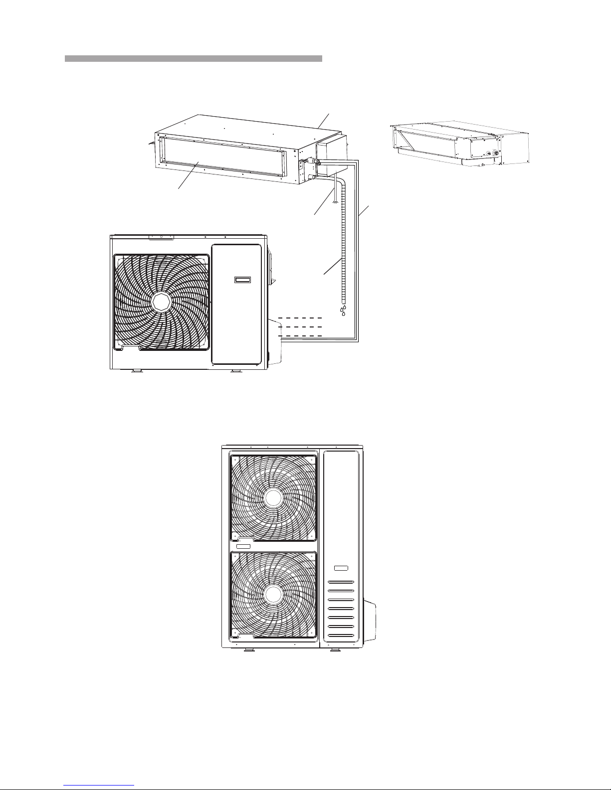
3
Composition of the Air-conditioner
Indoor unit (24K,36K,48K,60K)
Air inlet
Air outlet
The conditioned air is blown out of the
air-conditioner through it.
Power cord
Drainage
pipe
Refrigerant Pipes
The indoor and outdoor
units are connected by
copper pipes through
which the refrigerant flows.
Outdoor unit(18K/24K/36K)
Outdoor unit(48K,60K)
Indoor unit(18K)
Note:
Consequen tly,the shape may differ from th at of the air conditioner you have selected.
The figure is b ased on the external vie s of the standard model.
Page 7
FAN
MODE
T
I
MER
ON
CL
OC
K
I
F
E
E
L
TIM
E
R
OFF
S
LE
EP
SW
ING
SM
ART
S
U
P
ER
ON
OFF
ON/OF F
MODE FAN
SLEEP
SUPER
SMART
IFEEL DI MMER
TIMER ON T IMER OF F CLOCK
ON
OFFON OFF
SWING
SWING
4
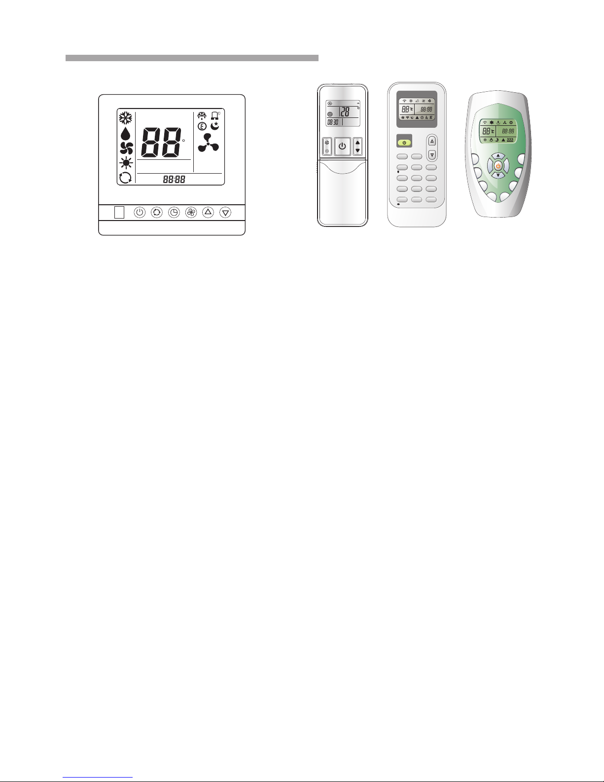
Composition of the Air-conditioner
You c an co ntr ol th e air -co nditioner wit h the w ire r emo te co ntr oll er an d wir eless remo te
con tro ller.
It is used for controlling power ON/OFF,
setting the running mode, temperature,
fan speed and other functions.
Wire remote controller
Wireless remote controller
SET TEMP
ROOM
TEMP
C
AUTO
NO
.
TIMER ON
TIMER OFF
SET TIMER
A
It is used for controlling wire remote controller,
setting the running mode, temperature, fan
speed and other functions.
Note : The standard duct air-conditioner don’t
consist of wireless remote controller, If you need
you may purchase it.
Page 8
5
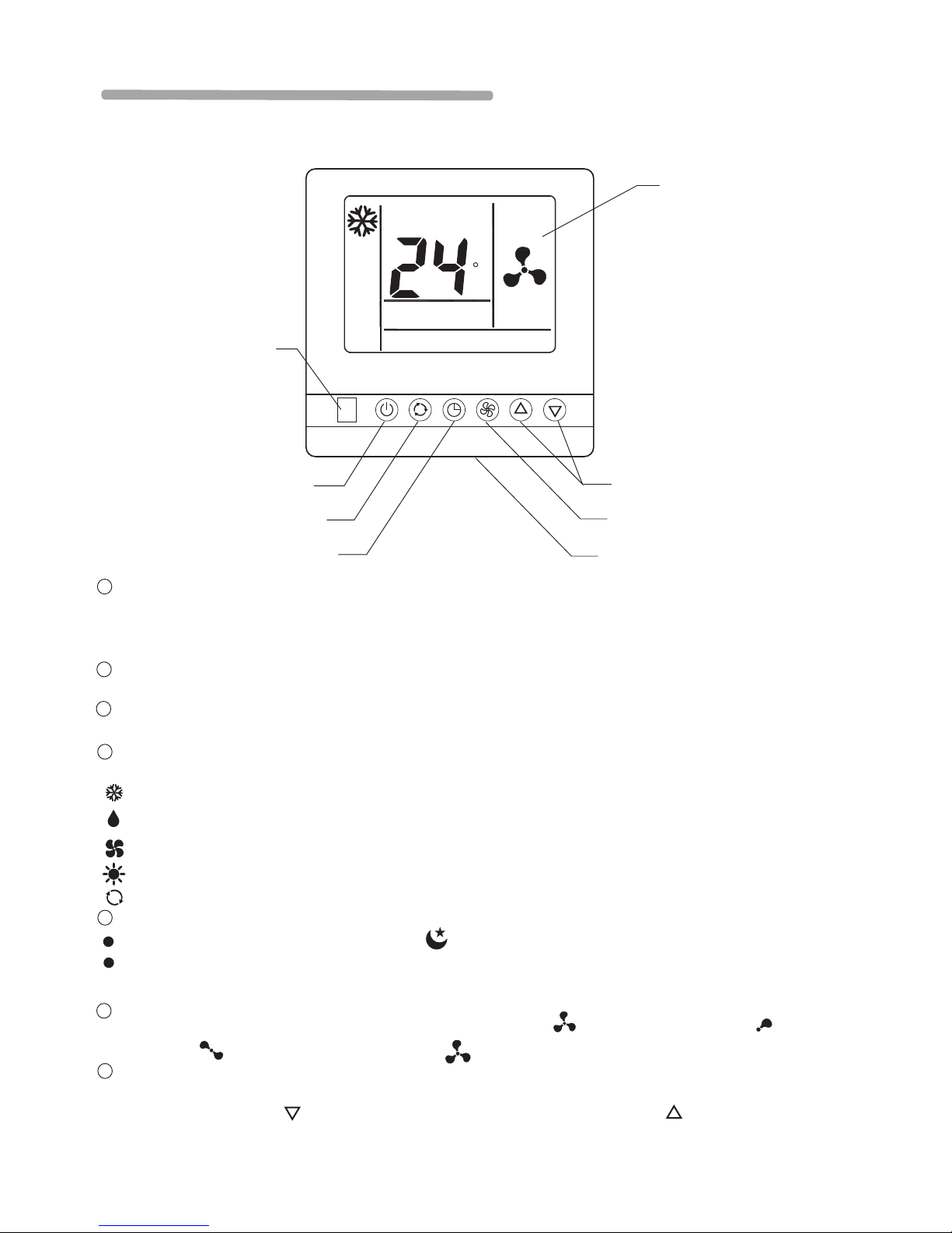
Remote controller operation manual
1.Wire remote controller introuce:
LCD screen
ROOM TEMP
TEMP. setting button
FAN speed button
Room temperature sensor
ON/OFF button
MODE select button
TIMER/SLEEP button
Wireless remoter receiver
1 . Room temperature sensor:
A temperature sensor inside the remote control switch is set to sense room temperature, and the temperature
will be sent to indoor unit. When do not connect the remote control switch, indoor unit will switch to the
temperature sensor which is built into indoor unit.
2 . Wireless remoter receiver:
by this receiver, you can use a additional wireless remoter switch to control indoor unit.
3 . ON/OFF button:
press this button to turn on or turn off the unit.
4 . MODE select button:
Press this button to select COOLING, DEHUMIDIFICATION, FAN , HEATING or AUTO-RUN mode.
COOLING mode, the air conditioner makes the room cool.
DEHUMIDIFICATION mode, the air conditioner reduces the humidity in the room.
FAN mode, the air conditioner makes the room's temperature suitable, providing the soft air flow.
HEATING mode, The air conditioner makes the room warm.
5 . TIMER/SLEEP button:
“ ” Press this button to active sleep mode, and will appear in LCD. Press again to cancel sleep function.
Press this button for 3 seconds to active timer function, Press for 3 seconds again to cancel timer function.
To timer function Pls. refer to 2.3
AUTO
C
“ ” “ ”
“ ” “ ”
“ ”
“ ” “ ”
6 . FAN speed button:
Press this button to change current fan speed. You can select (auto fan speed), (low fan
speed), (medium fan speed), and (high fan speed) by each press.
7 . TEMP Setting button:
Press the couple of buttons to set room temperature you want, when you press SET TEMP sign will
appear in LCD, press button to reduce setting temperature, and press button to increase
setting temperature.
AUTO-RUN mode, The air conditioner runs in right mode according to the temperature of room.
A
Page 9
6
remote controller operation manual
SET TEMP
ROOM
TEMP
C
AUTO
TIMER ON
TIMER OFF
SET TIMER
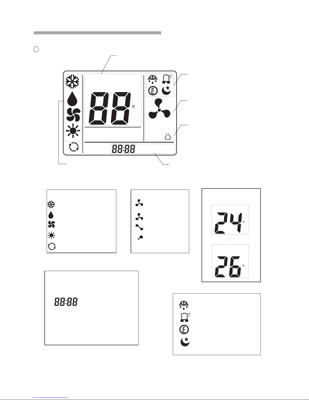
Display room temperature
and setting temperature
Running state sign area Which
indicate the running state
Fan speed display
8 .LCD screen
Flap direction display (For duct
type unit, this function is invalid)
Mode indication area Which indicate
the current running mode
Display timer setting
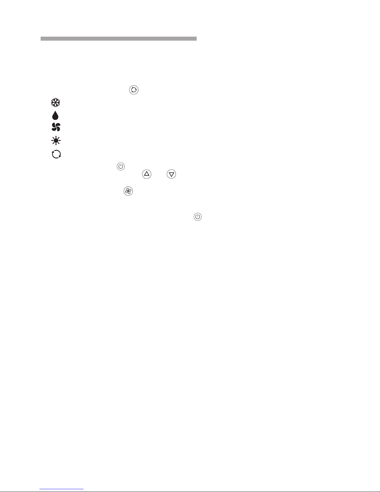
Operation mode
cooling mode
dehumidification mode
fan mode
heating mode
auto mode
Fan speed setting
auto fan
high fan speed
meddle fan speed
low fan speed
Temperature display
Room temperature:
Setting temperature:
ROOM
TEMP
C
SET TEMP
C
AUTO
A
TIMER ON
TIMER OFF
timer on
timer clock
timer off
Outdoor is defrosting
Compressor is running
Soft running mode is active
Sleep mode is active
A
A
NO
Page 10
7
remote controller operation manual
2. Operatio n with wire remote contr oller
2.1.1 Press M ODE button to select ope ration mode:“ ”
A
cooling mod e
dry mode
fan mode
heating mod e
auto-run mo de
2.1.2 Press O N/OFF button to turn on th e unit.
2.1.3 Press TEMP. SETTING button to set r oom temperature. The temperature
range can be se t from 18℃ to 32℃.
2.1.4 Press FA N button to set fan speed yo u want. Of course you can se t auto fan and indoor
unit will aut omatic select fan spee d according to the difference between room t emperature and
setting tem perature.
“ ”
“ ”“ ”
“ ”
2.1.5 You may turn off the unit b y press ON/OFF button ag ain.
Note:In fan m ode, temperature set ting is invalid.
“ ”
.
2. 1 Mode fun ction
Page 11
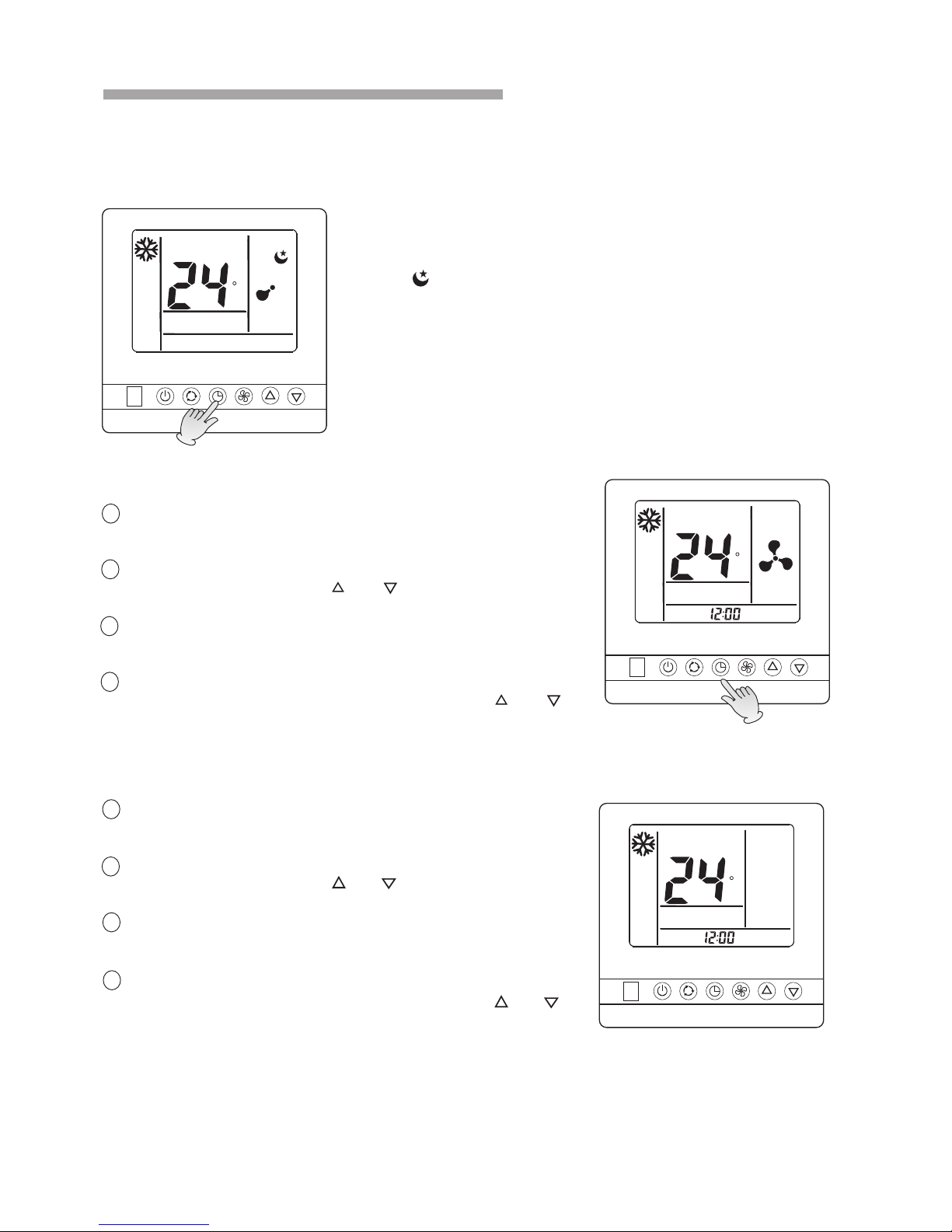
2. 2 sleep function
ROOM TEMP
C
Press timer /sleep button once to ac tive sleep function. An d sleep
sign“ ”will app ear on LCD.
Press timer /sleep button again to c ancel sleep function , and sleep
sign on LCD wil l disappear.
Note:
During fan mo de, auto mode,the slee p function is invalid.
2.3 Timer function
ROOM TEMP
C
TIMER OFF
2.3.1TIME R OFF mode
1 you can set tim er off when indoor uni t is running. By press
TIMER/SLE EP button for 3 seconds, timer clock appear on
LCD, and “TIME R OFF”flag will twinkle.
2 you can adjus t the time after which the i ndoor unit would turn
off automatically by press “ ” “ ” button. Th e time can
be set from 0.5 t o 24(or 12) hour in 30 minut es steps.
3 when you have s et the time, press TIMER/SLEEP button for
3 seconds aga in or wait for 5 seconds to ac tive the timer,
“TIMER OFF”fla g will stop twinkle, and t imer begin to work.
4 IF you need can cel “TIMER OFF”, press TIMER/SLEEP
button for 3 se conds to active the time r, Press “ ”“ ”
button set ti me 00: 00,Cancel “TIMER OFF”a fter 5
seconds aut omatically.
ROOM TEMP
C
TIMER ON
2.3.2 TIMER ON mode
1 you can set tim er on when indoor unit is sh ut off, By press
TIMER/SLE EP button for 3 seconds, timer clock appear on
LCD, and “TIME R ON” flag will twinkle.,
2 you can adjus t the time after which the i ndoor unit would turn
off automatically by press “ ” “ ” button. Th e time
can be set from 0 .5 to 24(or 12) hour in 30 min utes steps.
3 when you have s et the time, press TIMER/SLEEP button
for 3 seconds a gain or wait for 5 seconds t o active the timer,
“TIMER ON” flag w ill stop twinkle, and ti mer begin to work.
4 IF you need can cel “TIMER ON”,press TIMER/SLEEP
button for 3 se conds to active the time r, Press “ ”“ ”
button set ti me 00: 00,Cancel “TIMER On”af ter five
seconds aut omatically.
8
Timer clock
remote controller operation manual
Page 12
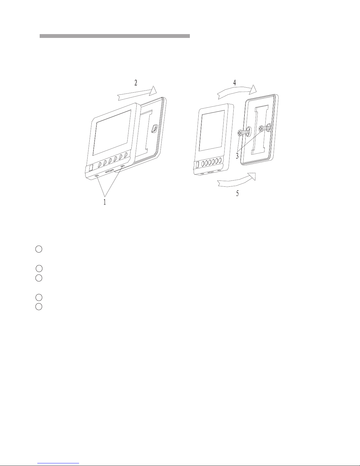
Installation of the wire remote controller please refer to the following:
remote controller operation manual
The wire remote controller must be installed by qualified installation technicians in accordance
with installation drawing instruction, the power should be shut off before installation. Air flow and
away from heating where the wire remote controller is installed. The following is process of
installation.
1 .Insert a minus screw driver into down slot (2 places).
Be careful not to damage the PC board with minus screw driver.
2 .Remove the back cover.
3 .Use two screw(φ4×16) to fasten the back and metal board in the mounting place and tighten
the screw, then link the communication wire.
4 .Fasten top cover into back cover.
5 .Fasten bottom cover into back cover.
9
3.wire Remote controller installation
Page 13
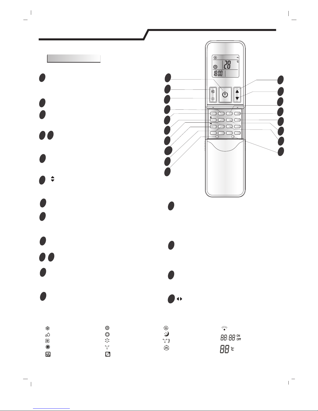
4.Wireless remote controller
4.1
The remote controller transmits signals to the system.
-H1
Remote controller
10
1
2
4
3
13
12
5
6
11
7
8
9
10
SUPER BUTTON
SWING BUTTON
FAN BUTTON
ROOM TEMPERATURE
SETTING BUTTONS
SLEEP BUTTON
DIMMER BUTTON
CLOCK BUTTON
ON/OFF BUTTON
SMART BUTTON
MODE BUTTON
TIMER ON/OFF BUTTON
Used to start or stop the fast cooling.
(Fast cooling operates at high fan speed with
18℃ set temp automatically)
Used to stop or start adjustment
louver swinging and set the desired up/down
airflow direction.
horizontal
SWING BUTTON
Used to stop or start adjustment
louver swinging and set the desired left/right
airflow direction.
vertical
*Some remote controller models without this button.
Used to select fan speed in sequence
auto, high, medium or low.
Used to set or cancel Sleep Mode operation.
The screen brightness is decreased each time
that button is pressed and it goes blank after
pressing the button four times.
Used to set the current time.
Used to enter fuzzy logic operation directly,
regardless of the unit is on or off.
The appliance will be started when it is
energized or will be stopped when it is
in operation, if you press this button.
Press this button to select the operation mode.
Used to set or cancel the timer operation.
Remote controller
Indication symbols on LCD:
Used to adjust the room temperature and
the timer, also real time.
14
MUTE BUTTON
Used to . set or cancel Mute mode operation
16
I FEEL BUTTON
Used to start or stop the I feel mode. Press this
button above 5 seconds , Turn off I FEEL mode.
(In I feel mode,the Air Conditioner operates basis
temperature sensor fitted in remote instead of machine,
Advice to use I FEEL mode and the remote put
where the indoor unit receive signal easily.)
15
TEP SWITCH BUTTON
Display set temperature flickeringly when the button is
pressed. Display indoor temperature when the button
is pressed again. And the flicker must be closed by
pressing the button or cutting off the electricity supply.
17
18*
SOFT BUTTON
Used to limit the maximum electric current,so that
you can use it with other electric instrument when
power is not enough.
( only effec tive for DC in verter model )
(inva lid for heat ing mode)
Note: Each mode and relevant function will be further specified in following pages.
Signal transmit.
Dry indicator
Fan only indicator
Heating indicator
Cooling indicator
High fan speed
Medium fan speed
Low fan speed
Display set temperature
Display set timer
Display current time
Auto fan speed Smart indicator
Sleep indicator
Mute indicator
Super indicator
Soft indicator
Cancel I feel indicator
10
11
12
13
3
4
1
2
6
7
5
8
9
MODE
CLOCK
TIMER ON
TIMER OFF
DIMMER
SMART
SWING
SWING
MUTE
TEP SWITCH
SLEEP
I FEEL
SOFT
14
16
17
15
18*
(inva lid for this m odel)
(inva lid for this m odel)
(inva lid for this m odel)
(inva lid for this m odel)
Page 14
How to Use
11
To operate the room air conditioner, aim
the remote controller to the signal receptor.
The remote controller will operate the air
conditioner at a distance of up to 8m when
pointing at signal receptor of indoor unit.
Remote controller
Remote controller
Signal receptor
MODE
CLOCK
TIMER ON
TIMER
OFF
DIMMER
SMART
MUTE
TEP
SWITCH
SLEEP
I FEEL
SOFT
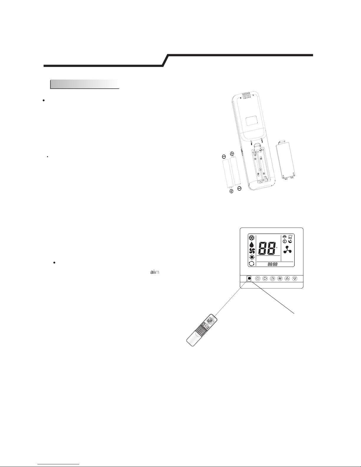
How to Insert the Batteries
Remove the battery cover according to the arrow direction.
Insert new batteries making sure that the (+) and (-) of
battery are matched correctly.
Reattach the cover by sliding it back into position.
Note:
Use 2 LR03 AAA(1.5volt) batteries. Do not use rechargeable batteries.
Replace batteries with new ones of the same type when the display
becomes dim.
SWING
SWING
SET TEMP
ROOM
TEMP
C
AUTO
NO
.
TIMER ON
TIMER OFF
SET TIMER
A
Page 15
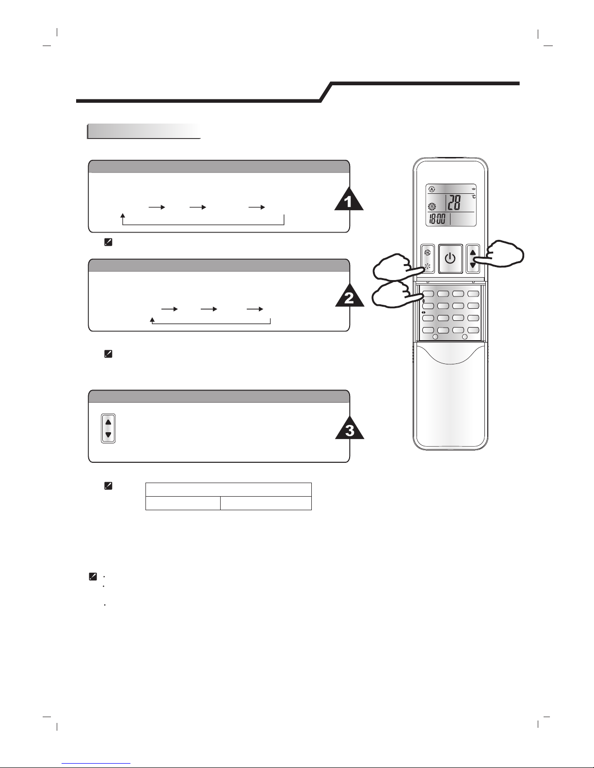
Each time MODE button is pressed, the operation mode
is changed in sequence:
Each time the "FAN" button is pressed, the fan speed is
changed in sequence:
18℃~32℃
Heating mode is NOT available for cooling only air conditioner.
HEATING
COOLING
DRY
FAN ONLY
Selecting mode
FAN mode
Auto
High Medium
Low
At "FAN ONLY" mode, only "High","Medium" and "Low" are available.
At "DRY" mode, Fan speed is set at "Low" automatically, "FAN" button
is ineffective in this case.
Setting temperature
Press once to lower temperature setting by 1℃
Press once to raise temperature setting by 1℃
Range of available set temperature
*HEATING, COOLING
SWING, SMART, TIMER ON, TIMER OFF, CLOCK, SLEEP and SUPER operation modes will be
specified in the following pages.
Changing modes during operation, sometimes the unit does not response at once. Wait 3 minutes.
Wait 3 minutes before restarting the appliance.
During heating operation, air flow is not discharged at the beginning. After 2-5 minutes, the air flow will be discharged
until temperature of indoor heat exchanger rises.
Operation instructions
12
Operation modes
Note: Heating mode is NOT available for cooling only models.
MODE
CLOCK
TIMER ON
TIMER OFF
DIMMER
SMART
MUTE
TEP SWITCH
SLEEP
I FEEL
SOFT
1
3
2
SWING
SWING
Page 16

Do not turn the vertical and horizontal adjustment louvers manually, otherwise malfunction may occur. If that happens,
turn off the unit first and cut off the power supply, then restore power supply again.
It is better not to let the adjustment louver tilt downward for a long time at COOLING or DRY mode to prevent
condensed water from dripping.
horizontal
Operation instructions
13
Airflow direction control
MODE
CLOCK
TIMER ON
TIMER OFF
DIMMER
SMART
MUTE
TEP SWITCH
SLEEP
I FEEL
SOFT
4
4
SWING
SWING
4
Airflow direction control
Vertical and horizontal airflow is automatically adjusted to a certain
angle in accordance with the operation mode after turning on the unit.
The direction of airflow can be
also adjusted to your own
requirement by pressing the
" " and the " "
button of the remote controller.
Operation mode
Direction of airflow
COOLING, DRY
*HEATING,
FAN ONLY
horizontal
downward
SWING
SWING
Vertical airflow control (with the remote controller)
Using remote controller to set various angles of flow or specific angle
as you like.
Swinging airflow
Pressing " " button once, the adjustment
louver will swing up and down automatically.
horizontal
Desired direction airflow
Pressing the " " button again when the louvers swing
to a suitable angle as desired.
Horizontal airflow control (with the remote controller)
Using remote controller to set various angles of flow or specific angle
as you like.
Swinging airflow
Pressing " " button once, the adjustment
louver will swing left and right automatically.
vertical
Desired direction airflow
Pressing the " " button again when the louvers swing
to a suitable angle as desired.
SWING
SWING
SWING
SWING
(inva lid for this m odel)
Page 17

SMART button is ineffective in SUPER mode.
Press the SMART button, the unit enters SMART mode(fuzzy logic operation) directly regardless of
the unit is on or off. In this mode, temperature and fan speed are automatically set based on the
actual room temperature.
Note: Temperature, airflow and direction are controlled automatically in SMART mode.
However, a decrease or rise of up to 7 ℃ can be set with the remote controller if you still
feel uncomfortable.
Operation instructions
14
SMART mode
Indoor temperature
Indoor temperature
Target temperature
Target temperature
Below T-3℃
Over T+3℃
T+3℃ or below
T
T
T
T
T
Over T+3℃
T-3℃ T+3℃≦Tindoor≦
Operation mode
Operation mode
HEATING
FAN ONLY
FAN ONLY
COOLING
COOLING
Operation mode and temperature are determined by indoor temperature
Heat pump models
Cooling only models
CLOCK button
You can adjust the real time by pressing CLOCK button, then
using and buttons to get the correct time, press
CLOCK button again the real time is set.
MODE
CLOCK
TIMER ON
TIMER OFF
DIMMER
SMART
MUTE
TEP SWITCH
SLEEP
I FEEL
SOFT
SWING
SWING
Your feeling
What you can do in SMART mode
button
adjustment procedure
Uncomfortable
because of
unsuitable air
flow volume.
Uncomfortable
because of
unsuitable flow
direction.
Uncomfortable
because of
unsuitable flow
direction.
Indoor fan speed alternates among
High, Medium and Low each time this
button is pressed.
Press it once, the adjustment
louver swings to change vertical airflow
direction. Press it again, swings stops.
horizontal
Press it once, the adjustment
louver swings to change horizontal airflow
direction. Press it again, swings stops.
vertical
SWING
SWING
Page 18

15
Timer mode
How to set TIMER ON
How to cancel TIMER ON
TIMER ON button can be used to set the timer programming as wished in order to
switch on the appliance at your desired time.
Press TIMER ON button, "12:00 ON" flashes on the LCD, then you
can press the or buttons to select your desired time for
appliance on.
Press the button once to increase or decrease the time setting by 1 minute.
Press the button 5 seconds to increase or decrease the time setting by
10 minute.
Press the button for a longer time to increase or decrease the time by 1 hour.
Press the TIMER ON button again, a "beep" can be heard and the indicator disappears,
the TIMER ON mode has been cancelled.
When your desired time displayed on LCD, press the TIMER ON button and confirm it.
A "beep" can be heard.
Note: If you don't set the time in 5 seconds after you press TIMER ON button, the remote controller
will exit the TIMER ON mode automatically.
Note: It is similar to set TIMER OFF, you can make the appliance switch off automatically at your
desired time.
The TIMER indicator on the indoor unit lights up.
"ON" stops flashing.
After the set timer displayed for 5 seconds the clock will be displayed on the LCD
of the remote controller instead of set timer.
It is convenient to set the timer on with TIMER ON buttons when you go out in the morning
To achieve a comfortable room temperature at the time you get home. You can also set
Timer off at night to enjoy a good sleep .with TIMER OFF
Operation instructions
Increase
or
or
or
Decrease
i)
ii)
iiI)
ON
Page 19

16
Operation instructions
SLEEP mode
SUPER mode
SLEEP mode can be set in COOLING, HEATING or DRYING operation mode,
This function gives you a more comfortable environment for sleep.
The appliance will stop operation automatically after operating for 8 hours.
In SLEEP mode,
Note: Heating is NOT available for cooling only air conditioner.
SUPER mode is used to start or stop fast cooling.
SUPER mode can be set when the appliance is in operation or energized.
Fast cooling operates at high fan speed, changing the set temperature
automatically to 18 . ℃
In SUPER mode, you can set airflow direction or timer. If you want to
escape from SUPER mode, press any - SUPER , MODE, FAN, ON/OFF
or TEMPERATURE SETTING button.
Note:
The Appliance will continue working in SUPER mode with set temperature of 18℃, if
you don't escape from it by pressing any of the buttons mentioned above.
SLEEP and SMART buttons are not available in SUPER mode.
SUPER button is ineffective in HEATING mode.
SLEEP mode
SUPER mode
MODE
CLOCK
TIMER ON
TIMER OFF
DIMMER
SMART
MUTE
TEP SWITCH
SLEEP
I FEEL
SOFT
MODE
CLOCK
TIMER ON
TIMER OFF
DIMMER
SMART
MUTE
TEP SWITCH
SLEEP
I FEEL
SOFT
SWING
SWING
SWING
SWING
(inva lid for heat ing mode)
Page 20

The remote controller transmits signals to the system.
Remote controller
17
13
SUPER BUTTON
Used to start or stop the fast cooling/heating.
(Fast cooling operates at high fan speed with
18℃ set temp automatically ; Fast heating
operates at auto fan speed with 32℃ set temp
automatically )
J1
Remote controller
Indication symbols on LCD:
Note: Each mode and relevant function will be further specified in following pages.
Signal transmit
Dry indicator
Fan only indicator
Heating indicator
Cooling indicator
High fan speed
Medium fan speed
Low fan speed
Display set temperature
Display is invalid
Display set timer
Display current time
Auto fan speed Smart indicator
Sleep indicator
I feel
Super indicator
ON
OFF
10
11
13
14
3
4
ON/OFF
MOD E FAN
SLE EP
SUP ER
SMA RT
IFE EL DI MMER
TIM ER ON TIM ER OFF CL OCK
ON
OFFON OFF
1
2
6
7
5
8
9
12
15
14
DIMMER BUTTON
The screen brightness is decreased each time
that button is pressed and it goes blank after
pressing the button four times.
*Note:Some remote controller models without buttons in the
dashed circle.
1
2
4
3
12
5
6
11
7
8
9
10
SWING BUTTON
FAN BUTTON
ROOM TEMPERATURE
SETTING BUTTONS
SLEEP BUTTON
I FEEL BUTTON
CLOCK BUTTON
ON/OFF BUTTON
SMART BUTTON
MODE BUTTON
TIMER ON/OFF BUTTON
Used to stop or start adjustment
louver swinging and set the desired up/down
airflow direction.
horizontal
15
SWING BUTTON
Used to stop or start adjustment
louver swinging and set the desired left/right
airflow direction.
vertical
Used to select fan speed in sequence
auto, high, medium or low.
Used to set or cancel Sleep Mode operation.
Used to start or stop the I feel mode. Press this
button above 5 seconds , Turn off I FEEL mode.
(In I feel mode,the Air Conditioner operates basis
temperature sensor fitted in remote instead of machine,
Advice to use I FEEL mode and the remote put
where the indoor unit receive signal easily.)
Used to set the current time.
Used to enter fuzzy logic operation directly,
regardless of the unit is on or off.
The appliance will be started when it is
energized or will be stopped when it is
in operation, if you press this button.
Press this button to select the operation mode.
Used to set or cancel the timer operation.
Used to adjust the room temperature and
the timer, also real time.
SWI NG
SWI NG
(inva lid for this m odel)
(inva lid for this m odel)
(inva lid for this m odel)
4.2
Page 21

How to Insert the Batteries
How to Use
Remove the battery cover according to the arrow direction.
Insert new batteries making sure that the (+) and (-) of
battery are matched correctly.
Reattach the cover by sliding it back into position.
Note:
Use 2 LR03 AAA(1.5volt) batteries. Do not use rechargeable batteries.
Replace batteries with new ones of the same type when the display
becomes dim.
18
To operate the room air conditioner, aim
the remote controller to the signal receptor.
The remote controller will operate the air
conditioner at a distance of up to 8m when
pointing at signal receptor of indoor unit.
Remote controller
Remote controller
Signal receptor
ON/OF
F
MODE
FAN
SWING
SLEEP
SUPER
IFEEL
DIMMER
TIMER ON
TIMER OFF
CLOCK
ON
OFFON OFF
SMART
SWING
SET TEMP
ROOM
TEMP
C
AUTO
NO
.
TIMER ON
TIMER OFF
SET TIMER
A
Page 22

Each time MODE button is pressed, the operation mode
is changed in sequence:
Each time the "FAN" button is pressed, the fan speed is
changed in sequence:
18℃~32℃
Heating mode is NOT available for cooling only air conditioner.
HEATING
COOLING
DRY
FAN ONLY
Selecting mode
FAN mode
Auto
High Medium
Low
At "FAN ONLY" mode, only "High","Medium" and "Low" are available.
At "DRY" mode, Fan speed is set at "Low" automatically, "FAN" button
is ineffective in this case.
Setting temperature
Press once to lower temperature setting by 1℃
Press once to raise temperature setting by 1℃
Range of available set temperature
*HEATING, COOLING
FAN
unable to set
SWING, SMART, TIMER ON, TIMER OFF, CLOCK, SLEEP and SUPER operation modes will be
specified in the following pages.
Changing modes during operation, sometimes the unit does not response at once. Wait 3 minutes.
Wait 3 minutes before restarting the appliance.
During heating operation, air flow is not discharged at the beginning. After 2-5 minutes, the air flow will be discharged
until temperature of indoor heat exchanger rises.
ONLY
Operation instructions
19
Operation modes
*Note: Heating mode is NOT available for cooling only models.
ON/OFF
MOD E FAN
SLE EP
SUP ER
SMA RT
IFE EL DIM MER
TIM ER ON T IMER O FF C LOC K
ON
OFFON OFF
1
3
2
SWI NG
SWI NG
Page 23

ON/ OFF
MODE FAN
SLEE P
SUPE R
SMAR T
IFEE L DIM MER
TIME R ON TIMER O FF CLOC K
ON
OFFON OFF
Do not turn the horizontal adjustment louvers manually, otherwise malfunction may occur. If that happens, turn off the unit
first and cut off the power supply, then restore power supply again.
It is better not to let the horizontal adjustment louver tilt downward for a long time at COOLING or DRY mode to prevent
condensed water from dripping.
Operation instructions
20
Airflow direction control
4
SWIN G
SWIN G
4
4
Airflow direction control
Vertical and horizontal airflow is automatically adjusted to a certain
angle in accordance with the operation mode after turning on the unit.
The direction of airflow can be
also adjusted to your own
requirement by pressing the
" " and the " "
button of the remote controller.
Operation mode
Direction of airflow
COOLING, DRY
*HEATING,
FAN ONLY
horizontal
downward
SWING
SWING
Vertical airflow control (with the remote controller)
Using remote controller to set various angles of flow or specific angle
as you like.
Swinging airflow
Pressing " " button once, the adjustment
louver will swing up and down automatically.
horizontal
Desired direction airflow
Pressing the " " button again when the louvers swing
to a suitable angle as desired.
Horizontal airflow control (with the remote controller)
Using remote controller to set various angles of flow or specific angle
as you like.
Swinging airflow
Pressing " " button once, the adjustment
louver will swing left and right automatically.
vertical
Desired direction airflow
Pressing the " " button again when the louvers swing
to a suitable angle as desired.
SWING
SWING
SWING
SWING
(invalid for this model)
Page 24

SMART button is ineffective in SUPER mode.
Press the SMART button, the unit enters SMART mode(fuzzy logic operation) directly regardless of
the unit is on or off. In this mode, temperature and fan speed are automatically set based on the
actual room temperature.
Note: Temperature, airflow and direction are controlled automatically in SMART mode.
However, a decrease or rise of up to 7 ℃ can be set with the remote controller if you still
feel uncomfortable.
Operation instructions
21
SMART mode
CLOCK button
You can adjust the real time by pressing CLOCK button, then
using and buttons to get the correct time, press
CLOCK button again the real time is set.
ON/ OFF
MOD E FAN
SLE EP
SUP ER
SMA RT
IFE EL DIMMER
TIM ER ON TIM ER OFF C LOCK
ON
OFF
FAN
SWI NG
SWI NG
SWI NG
SWI NG
Indoor temperature
Indoor temperature
Target temperature
Target temperature
Below T-3℃
Over T+3℃
T+3℃ or below
T
T
T
T
T
Over T+3℃
Operation mode
Operation mode
HEATING
FAN ONLY
FAN ONLY
COOLING
COOLING
Operation mode and temperature are determined by indoor temperature
Heat pump models
Cooling only models
Your feeling
What you can do in SMART mode
button
adjustment procedure
Uncomfortable
because of
unsuitable air
flow volume.
Uncomfortable
because of
unsuitable flow
direction.
Uncomfortable
because of
unsuitable flow
direction.
Indoor fan speed alternates among
High, Medium and Low each time this
button is pressed.
Press it once, the adjustment
louver swings to change vertical airflow
direction. Press it again, swings stops.
horizontal
Press it once, the adjustment
louver swings to change horizontal airflow
direction. Press it again, swings stops.
vertical
T-3℃ T+3℃≦Tindoor≦
Page 25

Timer mode
How to set TIMER ON
How to cancel TIMER ON
TIMER ON button can be used to set the timer programming as wished in order to
switch on the appliance at your desired time.
Press TIMER ON button, "ON 12:00" flashes on the LCD, then you
can press the or buttons to select your desired time for
appliance on.
Press the or button once to increase or decrease the time setting by 1 minute.
Press the or button one and a half seconds to increase or decrease the time
setting by 10 minute.
Press the or button for a longer time to increase or decrease the time by 1 hour.
Press the TIMER ON button again, a "beep" can be heard and the indicator disappears,
the TIMER ON mode has been cancelled.
When your desired time displayed on LCD, press the TIMER ON button and confirm it.
A "beep" can be heard.
Note: If you don't set the time in 10 seconds after you press TIMER ON button, the remote controller
will exit the TIMER ON mode automatically.
Note: It is similar to set TIMER OFF, you can make the appliance switch off automatically at your
desired time.
The TIMER indicator on the indoor unit lights up.
"ON" stops flashing.
After the set timer displayed for 5 seconds the clock will be displayed on the LCD
of the remote controller instead of set timer.
It is convenient to set the timer on with TIMER ON buttons when you go out in the morning
To achieve a comfortable room temperature at the time you get home. You can also set
timer off at night to enjoy a good sleep with TIMER OFF.
Operation instructions
Increase
Decrease
i)
ii)
iiI)
ON
22
Page 26

23
Operation instructions
SLEEP mode
SUPER mode
SLEEP mode can be set in COOLING, HEATING,DRYING operation mode.
This function gives you a more comfortable environment for sleep.
The appliance will stop operation automatically after operating for 8 hours.
In SLEEP mode,
Note: Heating is NOT available for cooling only air conditioner.
fast cooling
fast heating
SUPER mode can be set when the appliance is in operation or energized.
Fast cooling operates at high fan speed, changing the set temperature
automatically to 18
temperature automatically to 32 ℃.
℃;Fast heating operates at auto fan speed,changing the set
In SUPER mode, you can set airflow direction or timer. If you want to
escape from SUPER mode, press SUPER , MODE, FAN, ON/OFF,SLEEP
or TEMPERATURE SETTING button, the display will return to the original
mode.
Note:
The Appliance will continue working in SUPER mode , if you don't escape from it by
pressing any of the buttons mentioned above.
SMART button is not available in SUPER mode.
SLEEP mode
SUPER mode
ON/O FF
MODE FA N
SLEEP
SUPER
SMART
IFEEL DIMMER
TIMER O N TIMER OFF CLOC K
ON
OFF
ON
ON
OFF
ON
OFF
SUPER mode is used to start or stop fast cooling/fast heating.
SWING
SWING
Page 27

The remote controller transmits signals to the system.
24
1
2
4
3
13
12
5
6
11
7
8
9
10
SUPER BUTTON
SWING BUTTON
FAN BUTTON
ROOM TEMPERATURE
SETTING BUTTONS
SLEEP BUTTON
CLOCK BUTTON
ON/OFF BUTTON
SMART BUTTON
MODE BUTTON
TIMER ON/OFF BUTTON
Used to start or stop the fast cooling.
(Fast cooling operates at high fan speed with
18 C set temp automatically )
Used to stop or start vertical adjustment
louver swinging and set the desired up/down
airflow direction.
Used to select fan speed in sequence
auto, high, medium or low.
Used to set or cancel Sleep Mode operation.
Used to set the current time.
Used to enter fuzzy logic operation directly,
regardless of the unit is on or off.
The appliance will be started when it is
energized or will be stopped when it is
in operation, if you press this button.
Press this button to select the operation mode.
-E4-07
4.3
Used to set or cancel the timer operation.
Remote controller
Indication symbols on LCD:
Note:When insert the batteries into the remote controller first time all of the signs appear on the LCD for several seconds ,then
"Cooling" and "Heating"sign appears in turns , you can select "Heating" for heat pump models or "Cooling" for only cool
models.
Each mode and relevant function will be further specified in following pages.
Signal transmit.
Dry indicator
Fan only indicator
Heating indicator
Cooling indicator
High fan speed
Medium fan speed
Low fan speed
Display set temperature
Display set timer
Display current time
Auto fan speed Smart indicator
Sleep indicator
I FEEL indicator
Super indicator
ON
OFF
10
11
12
13
3
4
1
2
6
7
5
8
9
Used to adjust the room temperature and
the timer, also real time.
FAN
MODE
T
I
ME
R
ON
C
LO
C
K
I FE
E
L
T
IM
ER
OFF
SL
E
E
P
S
W
IN
G
S
MAR
T
SU
P
E
R
ON
OFF
(inva lid for this m odel)
8
I FEEL BUTTON
Press this button, turn on IFEEL mode.
remote controller operation manual
Page 28

How to Insert the Batteries
How to Use
Remove the battery cover according to the arrow direction.
Insert new batteries making sure that the (+) and (-) of
battery are matched correctly.
Reattach the cover by sliding it back into position.
Note:
Use 2 LR03 AAA(1.5volt) batteries. Do not use rechargeable batteries.
Replace batteries with new ones of the same type when the display
becomes dim.
25
To operate the room air conditioner, aim
the remote controller to the wire remote
controller. The remote controller will operate
the wire remote controller at a distance of
up to 8m when pointing at signal receptor
of the wire remote controller.
F
A
N
M
O
D
E
T
I
M
E
R
ON
CL
O
C
K
L
O
C
K
T
I
M
E
R
O
F
F
S
L
E
E
P
S
W
I
N
G
S
M
A
R
T
S
U
P
E
R
O
N
O
F
F
SET TEMP
ROOM
TEMP
C
AUTO
NO
TIMER ON
TIMER OFF
SET TIMER
A
remote controller operation manual
Page 29

Each time MODE button is pressed, the operation mode
is changed in sequence:
Each time the "FAN" button is pressed, the fan speed is
changed in sequence:
18℃~32℃
Heating mode is NOT available for cooling only air conditioner.
HEATING
COOLING
DRY
FAN ONLY
Selecting mode
FAN mode
Auto
High Medium
Low
At "FAN ONLY" mode, only "High","Medium" and "Low" are available.
At "DRY" mode, Fan speed is set at "Auto" automatically, "FAN" button
is ineffective in this case.
Setting temperature
Press once to lower temperature setting by 1℃
Press once to raise temperature setting by 1℃
Range of available set temperature
*HEATING, COOLING
FAN
unable to set
Turning on
SWING, SMART, TIMER ON, TIMER OFF, SLEEP,CLOCK and SUPER operation modes will be
specified in the following pages.
Press button, when the appliance receives the
signal, the RUN indicator of the indoor unit lights up.
(There is no RUN indicator for this model)
Changing modes during operation, sometimes the unit does not response at once. Wait 3 minutes.
Wait 3 minutes before restarting the appliance.
ONLY
26
Operation mode
*Note: Heating mode is NOT available for cooling only models.
FAN
MODE
T
I
M
ER ON
C
L
O
CK
I F
EE
L
TIM
E
R
O
F
F
S
L
E
EP
SW
I
N
G
SM
A
R
T
SUPER
ON
OFF
2
3
1
4
remote controller operation manual
Page 30

5
Airflow direction control
Vertical airflow is automatically adjusted to a certain angle
in accordance with the operation mode after turning on the unit.
The direction of airflow can be
also adjusted to your own
requirement by pressing the
"SWING" button of the
remote controller.
Operation mode
Direction of airflow
COOLING, DRY
*HEATING,
FAN ONLY
horizontal
downward
Vertical airflow control (with the remote controller)
Using remote controller to set various angles of flow or specific angle
as you like.
Swinging airflow
Pressing "SWING" button once, the horizontal adjustment
louver will swing up and down automatically.
Desired direction airflow
Pressing the "SWING" button again when the louvers swing
to a suitable angle as desired.
Horizontal airflow control (with hands)
Do not turn the horizontal adjustment louvers manually, otherwise malfunction may occur. If that happens, turn off the unit
first and cut off the power supply, then restore power supply again.
It is better not to let the horizontal adjustment louver tilt downward for a long time at COOLING or DRY mode to prevent
condensed water from dripping.
27
*Heating mode is only available for heat pump models.
Airflow direction control
SW
I
NG
FAN
MODE
T
I
M
E
R
O
N
CLO
C
K
I
FE
EL
T
I
ME
R
O
FF
SL
E
E
P
S
W
IN
G
S
MA
R
T
S
U
P
E
R
ON
OFF
remote controller operation manual
(inva lid for this m odel)
Page 31

SMART button is ineffective in SUPER mode.
Your feeling
What you can do in SMART mode
button
adjustment procedure
Press the SMART button, the unit enters SMART mode(fuzzy logic operation) directly regardless of
the unit is on or off. In this mode, temperature and fan speed are automatically set based on the
actual room temperature.
Uncomfortable
because of
unsuitable air
flow volume.
Uncomfortable
because of
unsuitable flow
direction.
Indoor fan speed alternates among
High, Medium and Low each time this
button is pressed.
Press it once, the horizontal adjustment
louver swings to change vertical airflow
direction. Press it again, swings stops.
Note: Temperature, airflow and direction are controlled automatically in SMART mode.
However, a decrease or rise of up to 7 ℃ can be set with the remote controller if you still
feel uncomfortable.
SMART mode
FAN
S
WI
N
G
FAN
MODE
T
I
M
ER
O
N
CL
OC
K
I
F
E
E
L
TIM
ER
OF
F
S
L
E
E
P
SW
IN
G
SMAR
T
SUP
ER
28
remote controller operation manual
CLOCK button
You can adjust the real time by pressing CLOCK button, then
using and buttons to get the correct time, press
CLOCK button again the real time is set.
4.3.4
Page 32

29
Timer mode
How to set TIMER ON
How to cancel TIMER ON
TIMER ON button can be used to set the timer programming as wished in order to
switch on the appliance at your desired time.
Press TIMER ON button, "ON 12:00" flashes on the LCD, then you
can press the or button to select your desired time for
appliance on.
Press the button once to increase or decrease the time setting by 1 minute.
Press the button one and a half seconds to increase or decrease the time
setting by 10 minute.
Press the button for a longer time to increase or decrease the time by 1 hour.
Press the TIMER ON button again, a "beep" can be heard and the indicator disappears,
the TIMER ON mode has been cancelled.
When your desired time displayed on LCD, press the TIMER ON button and confirm it.
A "beep" can be heard.
Note: If you don't set the time in 10 seconds after you press TIMER ON button, the remote controller
will exit the TIMER ON mode automatically.
Note: It is similar to set TIMER OFF, you can make the appliance switch off automatically at your
desired time.
The TIMER indicator on the indoor unit lights up.
"ON" stops flashing.
After the set timer displayed for 5 seconds the clock will be displayed on the LCD
of the remote controller instead of set timer.
It is convenient to set the timer on with TIMER ON button when you go out in the morning
To achieve a comfortable room temperature at the time you get home. You can also set
timer off with TIMER OFF button at night to enjoy a good sleep.
ON
Increase
or
or
or
Decrease
i)
ii)
iiI)
remote controller operation manual
Page 33

11
30
11
SLEEP mode
SUPER mode
SLEEP mode can be set in COOLING, HEATING,DRYING or SMART
This function gives you a more comfortable environment for sleep.
The appliance will stop operation automatically after operating for 8 hours.
In SLEEP mode,
Note: Heating is NOT available for cooling only air conditioner.
SUPER mode is used to start or stop fast cooling.
SUPER mode can be set when the appliance is in operation or energized.
Fast cooling operates at high fan speed, changing the set temperature
automatically to 18 . ℃
In SUPER mode, you can set airflow direction or timer. If you want to
escape from SUPER mode, press any - SUPER , MODE, FAN, ON/OFF
or TEMPERATURE SETTING button.
Note:
The Appliance will continue working in SUPER mode with set temperature of 18℃, if
you don't escape from it by pressing any of the buttons mentioned above.
SLEEP and SMART buttons are not available in SUPER mode.
SUPER button is ineffective in HEATING mode.
SLEEP mode
4.3.7
SUPER mode
FAN
MODE
T
IME
R ON
CL
O
C
K
I
FE
El
TI
MER
O
F
F
S
L
EE
P
S
W
I
NG
S
M
ART
S
U
PER
ON
FAN
MODE
T
I
ME
R
ON
CL
O
C
K
I
FE
E
L
T
I
M
E
R
O
FF
S
L
E
E
P
SWI
N
G
SM
A
R
T
S
U
P
E
R
operation mode.
remote controller operation manual
Page 34

31
Operation manual
5. Special remarks
·Cooling operation
In cooling mode, the temperature can be set between18℃—32℃ .
The fan of the indoor unit will never stop running. It remains running even if the compressor stops working.
·Heating operation
Since the air conditioner carries out the heating operation by drawing on the heat of the outside air (through
heating pump), the heating capacity may decrease if the temperature outside the room is too low. If the
heating effect is not so satisfying, use some other heating device together.
·Anti-freezing function during cooling
When the temperature of the air from the indoor outlet is too low, the unit will run for some time under the
fan mode, to avoid frost or ice forming in the indoor heat exchanger.
·Cold air prevention
In several minutes after the heating mode is started, the fan of the indoor unit will not run until the heat
exchanger of the indoor unit reaches a high enough temperature. That is because cold air prevention system
is operating.
·Defrosting
When the outdoor temperature is too low, frost or ice may form in the outdoor heat exchanger, reducing
heating performance. When this happens, a defrosting system of the air conditioner will operate. At the same
time the fan in the indoor unit stops(or runs at a very low speed in some cases),a few minutes later, the
defrosting is over, and the heating operation restarts.
·Blow out the survival heating air
When stop the air conditioner in normal operation, the fan motor would run in low speed for a while to blown
out the survival heating air.
·Self Recovery of Power Break
When the power supply is recovered after break, all preset are still effective and the air-conditioner can run
according to the original setting.
6. Troubleshooting
When the power supply is recovered after break, all preset are still effective and the air-conditioner can run
according to the original setting.
.1 If Trouble Still Remains ...
If the trouble still remains even after checking the following, contact your contractor and inform them of the
following items.
(1)Unit Model Name
(2)Content of Trouble
6.2 No Operation
6
Check whether the SET TEMP is set at the correct temperature.
CAUTION
3 minutes protect after compressor stop
For protect c ompressor, there are at l est 3 minutes stopping a fter compressor stop .
5 minutes protect
Compresso r must run 5 minutes at leas t once running. In the 5 min utes, compressor wil l not stop
even the room t emperature reach the s etting point unless yo u use remoter to turn off the unit(all
indoor unit b e turned off by user).
·
·
Page 35

32
Operation manual
6.3 Not Cooling or Heating Well
Check for obstruction of air flow of outside or inside units.
Check if too much heat source exists in the room.
Check if the air filter is clogged with dust.
Check to see if the doors or windows are opened or not.
Check if the temperature condition is not within the operation range.
6.4 This is Not Abnormal
Smells from indoor unit
Smell adheres on indoor unit after a long period of time. Clean the air filter and panels or allow a good
ventilation.
Sound from Deforming Parts
During system starting or stopping, an abrading sound might be heard. However, this is due to thermal
deformation of plastic parts. It is not abnormal.
Steam from Outdoor Heat Exchanger
During defrosting operation, ice on the outdoor heat exchanger is melted, resulting in making steam.
Dew on Air Panel
When the cooling operation continues for a long period of time under high humidity conditions(higher than
27℃/80%R.H.), dew can form on the air panel.
Refrigerant Flow Sound
While the system is being started or stopped, sound from the refrigerant flow may be heard.
Page 36

Diagram of refrigerant cycle
1.REFRIGERANT FLOW DIAGRAM
2.ELECTRICAL WIRING DIAGRAM
33
Gas piping
Wide service valve
Compressor
Accumulator
4-way valve
Heat exchanger
Liquid piping
Heating cycle
Cooling cycle
INDOOR UNIT OUTDOOR UNIT
Heat exchanger
EEV
Service valve
Note:
EEV is only valid for DC inverter air-conditioner,for air conditioner,use capillary.
Accumulator is only applicable to 48k and 60k air-conditioners.
Indoor unit
Outdoor unit
Indoor unit
Terminal Terminal
SI
L
N
SI
L
N
Power connecting cord
N
L
Power supply
Outdoor unit
Indoor unit
Terminal Terminal
SI
L
N
SI
L
N
Power connecting cord
N
L
Power supply
Power supply
Power supply
Outdoor unit
Indoor unit
Terminal Terminal
SI
L
N
SI
L
N
Power connecting cord
N
W
V
U
Outdoor unit
Terminal Terminal
SI
L
N
SI
L
N
Power connecting cord
N
W
V
U
48K/60K
36K/48K/60K
Outdoor unit
Indoor unit
Terminal Terminal
N
N
1L
3L
2L
1L
3L
2L
Power connecting cord
N
L
Power supply
18K
18K/24K/36K
24K
DC INVERTER UNITARY TYPE:
ON\OFF UNITARY TYPE:
Page 37

1. Safety Notice
34
Installation and Maintenance
WARNING
· Installation should be left to the dealer or another professional person. (Improper installation may cause
water leakage, electrical shock, or fire.)
·Install the unit according to the instruction given in this manual. (Incomplete installation may cause water
leakage, electrical shock, or fire.)
·Be sure to use the supplied or specified installation parts. (Use of other parts may cause the unit to come to
lose, water leakage, electrical shock, or fire.)
· Install the air conditioner on a solid base that can support the unit weight. (An inadequate base or
incomplete installation may cause injury in the event the unit falls off the base. )
· Electrical work should be carried out in accordance with the installation manual and the local national
electrical wiring rules or code of practice.
(Insufficient capacity or incomplete electrical work may cause electrical shock or fire. )
·Be sure to use a dedicated power circuit. (Never use a power supply shared by another appliance. )
·For wiring ,use a cable long enough to cover the entire distance with no connection, do not use an extension
cord.
·Do not put other loads on the power supply , use a dedicated power circuit. (Failure to do so may cause
abnormal heat, electric shock or fire.)
· Use the specified types of wires for electrical connections between the indoor and outdoor units. (Firmly
clamp the interconnecting wires so their terminals receive no external stresses.)
·Incomplete connections or clamping may cause terminal overheating or fire.
· After connecting interconnecting and supply wiring be sure to shape the cables so that they do not put
undue force on the electrical covers or panels. (Install covers over the wires, incomplete cover installation may
cause terminal overheating, electrical shock or fire.)
·When installing or relocating the system, be sure to keep the refrigerant circuit free from substances other
than the specified refrigerant (R410A) ,such as air. (Any presence of air or other foreign substance in the
refrigerant circuit causes an abnormal pressure rise or rupture, resulting in injury.)
·If any refrigerant has leaked out during the installation work, ventilate the room. (The refrigerant reduces a
toxic gas if exposed to flames.)
· After all installation is completed, check to make sure that no refrigerant is leaking out. (The refrigerant
produces a toxic gas if exposed to flames.)
·When carrying out piping connection, take care not to let air substances other than the specified refrigerant
go into refrigeration cycle. (Otherwise, it will cause lower capacity, abnormal high pressure in the refrigeration
cycle, explosion and injury. )
·Be sure to establish an earth. do not earth the unit to a utility pipe, arrester, or telephone earth. Incomplete
earth may cause electrical shock. (A high surge current from lightning or other sources may cause damage to
the air conditioner.)
·An earth leakage circuit breaker may be required depending on site condition to prevent electrical shock.
(Failure to do so may cause electrical shock. )
·Disconnect the power supply before completion of wiring, piping , or checking the unit.
·When moving the indoor unit and outdoor unit , please be careful .do not make the outdoor unit incline over
45 degree. Please avoid to be hurt by the sharp edge of the air conditioner.
· Install the remote controller: Be sure that the length of the wire between the indoor unit and remote
controller is within 50 meters.
·Do not install the air conditioner in a place where there is danger of exposure to inflammable gas leakage. (If
the gas leaks and builds up around the unit, it may catch fire.)
·Establish drain piping according to the instructions of this manual. (Inadequate piping may cause flooding.)
· Tighten the flare nut according to the specified method such as with a torque wrench. (If the flare nut is
tightened too hard, the flare nut may crack after a long time and cause refrigerant leakage.)
CAUTION
Page 38

During installation, do not damage the insulation
material on the surface of the indoor unit.
3. The Installation of the Indoor Unit
35
Installation and Maintenance
CAUTION
2. The Tools and Instruments for Installation
Number
1
2
3
4
5
6
7
Tool
Standard screwdriver
Vacuum pump
Charge hose
Pipe bender
Adjustable wrench
Tube cutter
Cross head screw-driver
Number
8
9
10
11
12
13
14
Tool
Gradienter
Hammer
Churn drill
Knife or wire stripper
Tube expander
Inner hexagon spanner
Tape measure
3.1 The Initial Check
·When moving the unit during or after unpacking,
make sure to lift it by holding its lifting lugs. DO not
exert any pressure on other parts, especially the
refrigerant piping, drain piping and flange parts.
· Wear protective gears (gloves and so on). When
install the unit.
CAUTION
300
or more
Maintenance
space
Fig. 3.2.1
20 or more
hh
Ceiling
*H≥50+h
2500 or more
Floor surface
(Length: mm)
Fig. 3.2.2
(unit:mm)
(unit:mm)
Model
Capacity(Btu/h)
h
18K 190
24K 270
36K
48K
60K
350
Model
Capacity(Btu/h)
h
18K 190
24K
36K
270
48K
60K
350
DC INVERTER UNITARY TYPE:
ON\OFF UNITARY TYPE:
Page 39

3.2 Installation
3.3.1 Suspension bolts
(1) Consider the pipe direction, wiring and maintenance
carefully, and choose the proper direction and location
for installation.
(2) Install the suspension bolts as shown in Fig. 3.3
below.
Fig. 3.3 Fixing the suspension bolts
·For the concrete
(Unit:mm)
·For t he stee l beam
·For the wooden beam
150 t o160m m
Screw in
(100 to150kg)
Steel bar
Concrete
Suspension bolts
(W3 /8 or M10 )
“ ” shaped steel beam
Wood rib
60mm to 90mm ( )
Woo den be am
Nut Round washer
Square washer
Suspension bolts
36
3.3.2 The position of the suspension bolts and the pipes
(1) Mark the positions of the , the
positions of the refrigerant pipes and the drain pipes.
(2) The dimension are shown below.
suspension bolts
Installation and Maintenance
·Optimum air distribution is ensured.
The air passage is not blocked.
Condensate can drain properly.
The ceiling is strong enough to bear the weight of
the indoor unit.
A false ceiling does not seem to be at an incline.
Sufficient clearance for maintenance and servicing
is ensured.(See Fig.3.2.1,Fig3.2.2 )
Piping between the indoor and outdoor units is
within the allowable limits.(refer to the installation of
the outdoor unit )
The indoor unit, outdoor unit, power supply wiring
and transmission wiring is at least 1 meter away
from televisions and radio, this prevents image
interference and noise in electrical appliances.
(Noise may be generated depending on the
conditions under which the electric wave is
generated, even if a one-meter allowance is
maintained.)
Use suspension bolts to install the unit, check
whether or not the ceiling is strong enough to
support the weight of the unit. If there is a risk that
the ceiling is not strong enough, reinforce the ceiling
before installing the unit.
For bottom intake, replace the chamber lid and the
intake-side flange in the procedure listed in fig.
(1) Remove the intake-side flange. Remove the
chamber lid.
(2) Reattach the removed chamber lid in the
orientation shown in FIG, reattach the removed
the intake-side flange in the orientation shown in
Fig. 3.2.3, refer to Fig.3.2.4 for the direction of
the intake-side flange.
·
·
·
·
·
·
·
·
Suspension bolts
(W3 /8 or M10 )
Nut
Fig. 3.2.3
Fig. 3.2.4
Intake-side flange
Chamber lid
Intake-side flange
Chamber lid
Filter(invalid for
Filter(invalid for this model)
this model)
18K
(unit:mm)
a b c d e f g h i j k l m n
DC-Inverter type 1207 1170 154 447 971 117 1039 170 117 150 199 13 81 84
ON/OFF Unitary
type
937 900 154 447 701 117 1235 170 117 150 199 13 81 84
Air intake
Air outlet
a
b
c
d
e
b
f
g
h
k
i
j
l
m
n
Page 40

Ai r in tak e
Ai r ou tlet
a
b
c
d
e
b
f
g
h
k
i
j
l
m
n
o
p
3.3.3 Install the indoor unit.
The installation of the indoor unit is shown in Fig. 3.5.
(1) How to fix the suspension bolts and the nuts
As shown in the figures 3.6, the nuts are fixed
four bolts.
Nut
Indoor unit
Washer
Double nut
Fig. 3.6 Suspension bolts and nuts
Approx 50mm
165 mm
Suspension bolts
( Field supplied )
(4-M10 or W3/8)
Nuts and
washers (4M1 0 or W3/ 8)
( Field supplied )
Fig. 3.5 The installation of the indoor unit
37
Fig. 3.4 Suspension bolts
(2) Install the indoor unit
As shown in the following figure, place the left
hanger bracket on the nuts and washers of the
suspension bolts.
Make sure that the left hanger bracket has been
fixed on the nuts and washers securely, install the right
hanger bracket suspension hook on the nuts and
washers.
(When installing the indoor unit, you can slightly
remove the suspension bolts.)
·
·
3.3.4 The horizon adjustment of the indoor unit
(1) Make sure that the hanger bracket is fixed by the nut
and the washer.
(2) Adjust the height of the unit.
(3) Check the unit is horizontally level.
(4) After the adjustment, tighten the nut and swear the
thread locker on the suspension to prevent the nuts
from loosening.
(1) During the installation, please cover the unit with the
plastic cloth to keep it clean.
(2) Make sure the unit is installed level using a level or
a plastic tube filled with water.. in using a plastic tube
instead of a level, adjust the top surface of the unit to
the surface of the water at both ends of the plastic tube
and adjust the unit horizontally.(one thing to watch out
for in particular is if it is installed so that the slope is not
in the direction of the drain piping, as this might cause
leaking.)
Installation and Maintenance
CAUTION
Rack
Double nuts
and washers
Hanger bracket
Suspension bolt
Indoor unit
Fig. 3.7
3.3.5 Installing the duct
·Make sure the range of the unit's external static
pressure is not exceeded.
·Connect the duct and intake-side flange.
·Connect the duct and outlet-side flange.
<Example>
CAUTION
Fig. 3.8
(Unit:mm)
a b c d e f g h i j k l m n o p
24K 934 900 669 720 805 222 835 228 242 294 378 405 25 156 202 214
36k(DC-Inverter type) 1334 1295 669 720 1205 222 1235 228 242 294 378 405 25 156 202 214
36k(ON/OFF Unitarytype) 1334 1295 740 796 1205 222 1235 228 237 312 375 405 25 204 203 242
48K&60K 1334 1295 740 796 1205 222 1235 228 237 312 375 405 25 204 203 242
Page 41

4. Refrigerant Pipe
Use the R410A refrigerant. When carrying on the
leakage check and test, do not mix in the oxygen, the
acetylene and flammable and the virulent gas, for
these gases are quite dangerous, and may possibly
cause explosion. It is suggested that the compressed
air, the nitrogen or the refrigerant be used to perform
these experiments.
4.1 The Pipe Material
(1) Prepare the copper pipe on the spot.
(2) Choose dustless, non-humid, clean copper pipe.
Before installing the pipe, use nitrogen or dry air to
blow away the tube dust and impurity.
(3)Choose the copper pipe according to Fig. 4.2.
4.2 The Connection of the Pipe
(1) The connection positions of the pipe are shown in
Fig. 4.1 and Fig. 4.2.
38
Fig. 4.1 The connection positions of the tube
Fig. 4.2 The pipe diameter
Model
Gas pipe
Liquid pipe
48K,60K
Φ19.05
φ9.52
78
61
35
The refrigerant gas pipe
The refrigerant liquid pipe
(2) As shown in Fig. 4.3, screw up the nuts with 2 spanners.
Fig. 4.3 Screw up the nut torque
(3) After finishing connecting the refrigerant pipes, keep
it warm with the insulation material.
φ6.35mm
φ9.52mm
φ12.7mm
φ15.88mm
φ19.05mm
Tube size
20
40
60
80
100
Torque(N.m)
Fig. 4.4 Piping insulation procedure
Clamp(attached)
Insulation (attached)
Refrigerant pipe
(field supplied)
Side of the
indoor unit
Insulation
( )field supplied
Installation and Maintenance
Canvas duct
Horizon
Service mouth
Air inlet
(with filter)
(600mm-600mm)
Air-outlet
The valve for the amount of air
Insulation material
Outside air
(through
the filter)
Static pressure
box
Canvas duct
Static pressure
box
The valve for
the amount of air
DANGER
Drain pipe connection hole
Fig. 3.9 Installing the duct
·The pipe go through the hole with the seal.
Protected with the tape or plug.
Do not put the pipes on the
floor directly.
CAUTION
·Do not put the pipes on the floor directly.
24K,36K
φ15.88
Φ9.52
Drain pipe
De32
De32
18K
Φ12.7
Φ6.35
De32
unit:mm
Page 42

39
5. Drain piping
Install the drain piping·
·
·
·
Make sure the drain works properly.
The diameter of drain pipe connection hole should
be same as that of the drain pipe.
Keep the drain pipe short and sloping down wards at
a gradient of at least 1/100 to prevent air pockets from
forming.
Refrigerant pipes
Drain pipe connection hole
(external straight pipe thread)
Water accumulating in the drain piping can cause
the drain to clog.
Refrigerant
pipes
Bucket
Portable pump
Air outlet
Drain outlet
Installation and Maintenance
CAUTION
CAUTION
·
·
·
·
·
·
To keep the drain tube from sagging, space hanging
wires every 1 to 1.5 m.
Use the drain hose and the clamp. Insert the drain
hose fully into the drain socket and firmly tighten the
drain hose and warm-keeping material with the clamp.
The two areas below should be insulated because
condensation may form there causing water to leak.
Drain piping passing indoors
Drain sockets.
Referring the figure below, insulate the drain socket
and drain hose using the included large sealing pad.
Drain piping connections
Do not connec t the drain directly to se wage
pipes that sm ell of ammonia. The am monia in the
sewage migh t enter the indoor unit th rough the
drain pipes a nd corrode the heat exch anger.
Do not twist or b end the drain hose ,so tha t
excessive f orce is not applied to it.
This type of tr eatment may cause leak ing.
After pipin g work is finished, chec k drainage
flows smoot hly.
Gradually i nsert approximatel y 1000 cc of water
into the drai n pan to check drainage in t he manner
described b elow.
Gradually p our approximately 10 00 cc of water
from the outl et hole into the drain pan t o check
drainage.
Check the dra inage.
·
·
·
·
·
·
Drain hose
Sealing material Sealing material
Page 43

may result in accident, for example shock.
(1) As shown in Fig. 6.1, remove the screws on the control box.
(2) Connect the power cord and earth wire to the main terminal.
(3) The remote control wire to the subsidiary terminal box.
(4) Connect the power supply of the indoor and outdoor units to the main terminal.
(5) Tie the wire in the control box with the clamp tightly.
(6) After finishing the wiring, seal the wiring hole with
the sealing material ( with the lid ) to prevent the condensed water and insects entering.
·If the fuses burn up, please call the service agency to instead it. Please do not instead by yourself, or else
Air inletAir outlet
The lid of the control box
Remove the screws on the control box
40
Installation and Maintenance
WARNING
Fig.6.1
6. Electrical wiring
· When clamping the wiring, use the included clamping material as shown in the FIG.6.1 to prevent outside
pressure being exerted on the wiring connections and clamp firmly.
When doing the wiring, make sure the wiring is neat and does not cause the control box lid to stick up, then
close the cover firmly. When attaching the control lid, make sure you do not pinch any wires.
Outside the machine, separate the weak wiring(remote controller and transmission wiring) and strong
wiring(earth and power supply wiring) at least 50 mm so that they do not pass through the same place
together. Proximity may cause electrical interference. Malfunction , and breakage.
·
·
CAUTION
6.1 General check
Page 44

Installation and Maintenance
6.2 change of Static pressure
Fig 6.2
WHT
RED
Fan motor
Low static pressure
High static pressure
The static pressure outside the indoor unit can be chosen .
6.2.1 Models except 24K & 36K (High-Efficiency DC-Invert type ):
6.2.2 24K & 36K (High-Efficiency DC-Invert type ):
You can change the static pressure by changing the fan motor terminal which refer to following Fig6.2.
The static pressure can be freely adjusted from 1 Pa to 80 Pa by using specific wire remote controller.
Operation details, please refer to wire remote controller manuals .
Default static pressure is 30 Pa.
If you still have any trouble, please contact local technical service center of our company for further information.
Note:
The noise under high static pressure is higher than static pressure .
41
Model
High static
pressure
Low static
pressure
18K
30Pa
10Pa
24K,36K
48K,60K
80Pa
120Pa
50Pa
80Pa
Default S ettings is by factory.low stati c pressure
Page 45

42
Installation and Maintenance
7. The Installation of the Outdoor Unit
Avoid
Direct sunlight
Near Heat Source/ventilation fan
Container With Flammable materials
Thick Oil fog
Wet Or Uneven place
Aisle Or sideway
7.1 Installation sites
Pl
Place it in an area with good ventilation.
Have desired space for air inlet, outlet and
maintenance. (Figure 7.1)
2
Make a strong base(10X40cm board made of
concrete or alike). The appliance should be placed
not less than 10 cm high to avoid being wet or
corroded. Otherwise, it may cause damage to the
appliance or reduce its life time. (Figure 7.2)
Fix the base with hook bolts or alike to reduce
vibration and noise.
ace it in cool temperature.
You should
If the total tube length is between 5m and 50m (Max.
length), an additional refrigerant can be added. It's not
necessary to add compressor oil.(Figure 7.3)
Obstacle
Top obstacle
Air outlet
2m
2m
Ground
Min.10cm
Air inlet
Min. 10cm
Min.
5cm
Air outlet
Air inlet
Min.
5cm
Min.40cm
Fig. 7.1
Concrete base or alike
Min.10cm
Setscrew
(at least 4)
About 40cm
About 10cm
Fig.7.2
Fig.7.3
7.2 Installation of the outdoor unit
Firstly select the installation site and fix the outdoor
unit. If it needs to be fixed onto the wall, make sure
that the wall and the supporting rack is strong enough
to hold the weight of the appliance.
Release the setscrews of the electric cover,
remove the electric cover(if the valve cover is
there either, please release it. )
Connect the indoor unit wiring to the outdoor unit
panel according to the electric wiring diagrams.
Be sure to make each wire allowing 10cm longer
than the required length for wiring.
Ground the unit following local electrical
regulations.
Check the wiring with the wiring diagrams and
make sure it's well connected. Fix the wiring with
clips and reinstall the electric cover.
Wiring instruction for outdoor unit
Indoor unit
Tube length L
Height difference H
Outdoor unit
48k/60k
48k/60k
20(m) 10(m) 15(g/m)
15(m) 7.5(m) 15(g/m)
20(m) 10(m) 35(g/m)
20(m) 10(m) 35(g/m)
30(m) 20(m) 35(g/m)
30(m) 15(m) 35(g/m)
50(m) 30(m) 35(g/m)
50(m) 15(m) 35(g/m)
Max. Tube
length(L)
Max. Tube
length(L)
Model
Model
DC-INVERTER type
ON/OFF UNITARY type
18k
18k
24k*
24k
36k
36k
Max. Height
difference(H)
Max. Height
difference(H)
Add.
Refrigerant
(exceed 5m)
Add.
Refrigerant
(exceed 5m)
*For 24k :Tuber length between
indoor and outdoor is the same as 36k types.
(High-Efficiency DC-Invert type )
Page 46

Installation and Maintenance
43
8.2 Connecting tubing between indoor
and outdoor Units
Be sure to apply a sealing cap or water-proof tape
to prevent dust or water from getting into the tubes
before they are used.
Be sure to apply refrigerant lubricant to the
matching surfaces of the flare and union before
connecting them together. This is effective for
reducing gas leaks.(Figure 8.4)
For proper connection, align the union tube and
flare tube straight with each other, then screw in the
flare nut lightly to obtain a smooth match. (Figure 8.5)
Tighten the setscrew with torque wrench to prevent
leak of refrigerant. Carefully test leak before running
the appliance.
Remove the burrs at the end of the copper tube
with a tube reamer or file. When reaming, hold the
tube bend downward and be sure that no copper
scraps fall into the tube. This process is important
and should be done carefully to make a good
flare.(Figure 8.1,8.2)
Remove the flare nut from the unit and be sure to
mount it on the copper tube.
Make a flare at the end of copper tube with a flare
tool.(Figure 8.3)
8.4 Taping the Tubes
Note: Do not wind the armoring tape too tightly because
this will decrease the heat insulation effect. Also be
sure the condensation drain hose splits away from
bundle and drips clear of the unit and the tubing.
The two refrigerant tubes (and electrical wire if local
codes permit)should be taped together with white
armoring tape. The drain hose may also e included
and taped together as a bundle with the tubing.
Wrap the armoring tape from the bottom of the
outdoor unit to the top of the tubing where it enters
the wall. As you wrap the tubing, overlap half of
each previous tape turn. (See Figure 8.7)
Clamp the tubing bundle to the wall, using one
clamp approx. every 120 cm.
8.5 Finishing the installation
After completion of wrapping and insulation, seal the
hole on the wall with suitable sealant against wind and rain.
To avoid loss of heat and in prevention of the
ground being wet by condensed water, all
refrigerant tubes must be insulated with suitable
insulating materials whose minimum thickness will
be 6 mm. (See Figure 8.6)
8.3 Heat insulation of the refrigerant tube
9.Air purging and test run
Air and moisture remaining in the refrigerant system
have undesirable effects.
Therefore, they must be purged completely following the
steps.
9.1 Air Purging with a Vacuum Pump (See
Figure 9.1, Figure 9.2)
(1) Check that each tube (both narrow and wide tubes
between the indoor and outdoor units) have been
properly connected and all wiring for the test run has
been completed. Note that both narrow and wide tube
valves on the outdoor unit are kept closed at this stage.
(2) Using an adjustable wrench or box wrench, remove
the bonnet from the service valve.
(3) Connect a vacuum pump and service valve together
tightly.
(4) Turn on the vacuum pump and till the pressure is
-4
lower than 15Pa(or 1.5×10 bar) for 5 minutes.
(5) With the vacuum pump still running, demount tube
of vacuum pump from the service valve. Then stop the
vacuum pump.
(6) Replace the bonnet on the service valve and fasten it
securely with an adjustable wrench or box wrench.
(7) Using an adjustable wrench or box wrench, remove
the bonnet of both narrow and wide valve.
(8) With the hex wrench, turn the wide and narrow tube
valves stem counter clockwise to fully open the valves.
(9) Replace the bonnets on the wide and narrow valves
and fasten it securely with an adjustable wrench or box
wrench.
8.1 Flaring with tube expander
Note: A good flare have the following characteristics:
Inside surface is glossy and smooth.
Edge is smooth.
Tapered sides are of uniform length.
8.Refrigerant tubing
Page 47

The trial should be carried out according to the
installation and maintenance manual.
Only after all the checking points have been checked
the unit can be operated.
(A) Check and make sure that the resistance of the
terminal to ground is more than 1M , otherwise, you
cannot operate the unit before the electricity leakage
point is found and repaired.
(B) Check and make sure that the stop valve has been
opened before operating the unit.
·
Ω
WARNING
Installation and Maintenance
44
9.2 Leak test
Leak test all joints and valves of the indoor unit and
outdoor unit with liquid soap. Checking of the orifice
cap shouldn't be less than 30 seconds. Clean the
liquid soap after the test in case that the color of
the copper tube may change for erode.
9.3 Tidy up the tubing
If the leak test turns out to be all right, preserve heat
the joints of the indoor unit.
Straighten the connecting tubes and make them
flush and fixed to the wall. Seal the space around the
hole in the wall through which the tubes come out
with gypsum.
9.4 Test Run
Make sure the power and unit run well then plug in.
Turn on the appliance and adjust it to Cooling,
dehumidifying and Heating mode according to the
room temperature. Check if the appliance can run
well.
Installation of the appliance is generally finished after
the above operations are done. If you still have any
trouble, please contact local technical service center
of our company for further information.
Clamp
Insulated tubes
Tube
Tapered nuts
Flarer
Fig.8.3
Apply refrigerant lubricant here and there
Union Flare nut
Insulation
Narrow tube
Hex wrench
Wide tube
Service valve
Bonnet of service valve
Bonnet of narrow valve
Bonnet of wide valve
Indoor unit
Outdoor unit
Manifold
valve
Pressure
gauge
Vacuum pump
Reamer
Tube
Fig.8.1
Before
After
Fig.8.2
Fig.8.5
Fig.8.4
Fig.8.6
Fig.8.7
Fig.9.1
Fig.9.2
Page 48

Installation and Maintenance
9.5 Common
● Use an ELB (Electric Leakage Breaker). If not used, it will cause an electric shock or a
fire.
● Do not operate the system until all the check points have been cleared.
(A) Check to ensure that the insulation resistance is more than 1 megohm, by measuring the
resistance between ground and the terminal of the electrical parts. If not, do not operate the
system until the electrical leakage is found and repaired.
(B) Check to ensure that the stop valves of the outdoor unit are fully opened and then start the
system.
● Pay attention to the following items while the system is running.
(A) Do not touch any of the parts by hand at the discharge gas side, since the compressor
chamber and the pipes at the discharge side are heated higher than 90℃.
(B) DO NOT PUSH THE BUTTON OF THE MAGNETIC SWITCH(ES). It will cause a serious
Accident.
NOTES:
1) Follow local codes and regulations when selecting field wires.
2) The wire sizes marked in the table are selected at the maximus current of the unit according to the
European Standard ,En60 335-1.
3) Use a shielded cable for the transmitting circuit and connect it to ground .
4) In the case that power cables are connected in series, add each unit maximum current and
select wires below.
*in the case that current exceeds 63A, do not connect cables in series.
Use the wires which are not lighter than the ordinary polychloroprene
sheathed flexible cord (code designation H07RN-F) .
To be in compliance with EN 61000-3-11, the product shall be connected only to a supply of the system impedance:
︱Zsys︱≤0.247Ω(for 18Κ ΟΝ/ΟFF Unitary type) ︱Zsys︱≤0.209Ω(for 24Κ ΟΝ/ΟFF Unitary type).Before
connecting the product to public power network,please consult your local power supply authority to ensure the
power network meet above requirement.
5)
45
18K(DC Inverter Unitary Type)
18K(On\Off Unitary Type)
24K
36K(On\Off Unitary Type)
48K
60K
220~240V,50Hz
220~240V,50Hz
220~240V,50Hz
3X1.5mm
5X1.5mm
3X1.5mm
3X2.5mm
5X2.5mm
5X1.5mm
4 0.75mm X
4 0.75mm X
4 0.75mm X
4 0.75mm X
2
2
2
2
2
2
2
2
2
2
380~415V,50Hz
380~415V,50Hz
Power
Supply
EN60 335-1
EN60 335-1
Capacity
(Btu/h)
Transmitting Cable Size
36K ( )DC Inverter Unitary Type
SWING
Page 49

Correct Disposal of this product
This marking indicates that this product should not be disposed with other household wastes
throughout the EU. To prevent possible harm to the environment or human health from
uncontrolled waste disposal, recycle it responsibly to promote the sustainable reuse of material
resources. To return your used device, please use the return and collection systems or contact
the retailer where the product was purchased. They can take this product for environmental safe
recycling.
Version No. 1504005,G
PACKING LIST
OUTDOOR UNIT PACKING LIST
INDOOR UNIT PACKING LIST
NO.
NAME
AMOUNT
1
2
3
4
5
NO. AMOUNT
INDOOR UNIT
MANUAL
1
1
1
1
1
NO.
NAME
AMOUNT
1
2
NO. AMOUNT
OUTDOOR UNIT
DRAINAGE ELBOW
1
1
INDOOR ACCESSORIES 1
INDOOR ACCESSORIES 2
6
WIRE REMOTE CONTROLLER
1
INDOOR ACCESSORIES 3
*
*
:Invalid for18k types.
 Loading...