

Hisense AUC-18HR4SAA, AUC-24HR4SGA, AUC-36HR4SGA, AUC-48HR4SHA, AUC-60HR4 SHA User Manual
...Page 1
We,
Hisense International Co., Ltd
Hisense(Shandong) Air-conditioning Co.,Ltd.
No.8 Ronggang Road, Ronggui, Shunde,Foshan, Guangdong, P.R.China
No.1 Hisense Road, Nancun, Pingdu,Qingdao, Shandong Province, P.R.China
( Supplier Address & Factory Address )
declare under our sole responsibility that the product
AIR CONDITIONER
(Category Name)
GBF18H-S GDF18H-S GFF18H-S GCF18H-S
GBF24H-S GDF24H-S GFF24H-S GCF24H-S
GBF36H-S GDF36H-S GFF36H-S GCF36H-S
GBF48H-S GDF48H-S GFF48H-S GCF48H-S
GBF60H-S GDF60H-S GFF60H-S GCF60H-S
(Model Name)
to which this declaration relates is in conformity with the technical requirements of the
following standard(s)
EMC Directive- 2014/30/EU
Low Voltage Directive-2014/35/EU
CE Marking Directive-93/68/EEC
LVD standard EMC standard
EN 60335-1:2012+A11:2014 EN 55014-1:2006
EN 60335-2-40:2003 +A1:2009+A2:2011
+A11:2004+A12:2005+A1:2006+A2:2009 EN 55014-2:1997 +A1:2001+A2:2008
+A13:2012 EN 61000-3-2:2014
EN 62233:2008 EN 61000-3-2:2014
EN 61003-3-3:2013
Page 2
We, hereby further declare that the following products (Product catalog) are exactly the same,
only difference being the art work.
Factory Model No.
AUC-18HR4SAA GBF18H-S Galactic R410a, On/Off, 18000Btu,CASSETTE type indoor unit
AUC-24HR4SGA GBF24H-S Galactic R410a, On/Off, 24000Btu,CASSETTE type indoor unit
AUC-36HR4SGA GBF36H-S Galactic R410a, On/Off, 36000Btu,CASSETTE type indoor unit
AUC-48HR4SHA GBF48H-S Galactic R410a, On/Off, 48000Btu,CASSETTE type indoor unit
AUC-60HR4 SHA GBF60H-S Galactic R410a, On/Off, 60000Btu,CASSETTE type indoor unit
AUD-18HX4SNL GDF18H-S Galactic R410a, On/Off, 18000Btu,DUCT type indoor unit
AUD-24HX4SLH GDF24H-S Galactic R410a, On/Off, 24000Btu,DUCT type indoor unit
AUD-36HX4S1HH GDF36H-S Galactic R410a, On/Off, 36000Btu,DUCT type indoor unit
AUD-48HX4SHH GDF48H-S Galactic R410a, On/Off, 48000Btu,DUCT type indoor unit
AUD-60HX4SHH GDF60H-S Galactic R410a, On/Off, 60000Btu,DUCT type indoor unit
AUV-18HR4SA GFF18H-S Galactic R410a, On/Off, 18000Btu,FLOOR-CEILING type indoor unit
Client Model
No.
Brand Type/Description/Feature
AUV-24HR4SA GFF24H-S Galactic R410a, On/Off, 24000Btu,FLOOR-CEILING type indoor unit
AUV-36HR4SB GFF36H-S Galactic R410a, On/Off, 36000Btu,FLOOR-CEILING type indoor unit
AUV-48HR4SC GFF48H-S Galactic R410a, On/Off, 48000Btu,FLOOR-CEILING type indoor unit
AUV-60HR4SC GFF60H-S Galactic R410a, On/Off, 60000Btu,FLOOR-CEILING type indoor unit
AUW-18H4SU1 GCF18H-S Galactic R410a, On/Off, 18000Btu,universal outdoor unit
AUW-24H4SZ1 GCF24H-S Galactic R410a, On/Off, 24000Btu,universal outdoor unit
AUW-36H6S1A1 GCF36H-S Galactic R410a, On/Off, 36000Btu,universal outdoor unit
AUW-48H6SE1 GCF48H-S Galactic R410a, On/Off, 48000Btu,universal outdoor unit
AUW-60H6SP1 GCF60H-S Galactic R410a, On/Off, 60000Btu,universal outdoor unit
King Huang Product Manager
Name of authorized officer Title of authorized officer
2017-03-12Date of issue Signature & company seal
Page 3
11.. GGEENNEERRAAL
L
ON/OFF UNITARY AIR CONDITIONER TECHNICAL& SERVICE MANUAL V6.0 1
1-1 Features
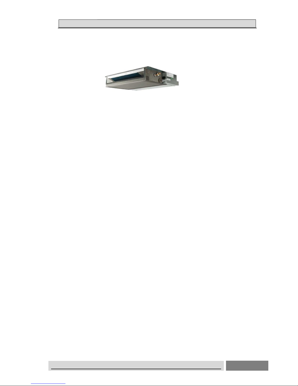
Duct Type Air Conditioner
Features
➢ Save Installation Space
The indoor unit can be installed inside the ceiling conveniently.
➢ Optional Static Pressure
18k: optional 10Pa /30Pa, 24K/36K 50Pa/80Pa 48K/60K: 80Pa/120Pa static Pressure.
One unit, mute optional installation method.
➢ High Efficiency and Environment Friendly New Refrigerant-R410A
R410A can protect the environment and do not harm to the ozone layer.
➢ 24-hour Timer ON and OFF
This Timer can be set to automatically turn the unit on or off within a 24-hour period.
➢ Mute Operation
The excellent fan design enable the airflow to be quiet and smooth with minimum
noise.
➢ Meeting Various Installation Requirements
The back-air-inlet type is usually to be adopted according to the actual installation
space.
The unit is also installed with down-air-inlet type and the noise will increase about 5-6
dB.
Page 4

11.. GGEENNEERRAAL
L
ON/OFF UNITARY AIR CONDITIONER TECHNICAL& SERVICE MANUAL V6.0 2
➢ Self Recovery of Power Break
When the power supply is recovered after break, all preset are still effective and the
air-conditioner can run according to the original setting.
➢ Fault Self-diagnose Function
When there is something wrong with the air-conditioner,the micro computer could
diagnose the faults, which can be read from the display and is convenient for
maintenance.
Page 5

11.. GGEENNEERRAAL
L
ON/OFF UNITARY AIR CONDITIONER TECHNICAL& SERVICE MANUAL V6.0 3
Cassette Type Air Conditioner
Features
➢ Save Installation Space
The indoor unit can be installed inside the ceiling conveniently.
➢ High Efficiency and Environment Friendly New Refrigerant-R410A
R410A can protect the environment and do not harm to the ozone layer.
➢ 24-hour Timer ON and OFF
This Timer can be set to automatically turn the unit on or off within a 24-hour period.
➢ Mute Operation
The excellent fan design enable the airflow to be quiet and smooth with minimum noise.
➢ Self Recovery of Power Break
When the power supply is recovered after break, all preset are still effective and the
air-conditioner can run according to the original setting.
➢ Fault Self-diagnose Function
When there is something wrong with the air-conditioner, the micro computer could
diagnose the faults, which can be read from the display and is convenient for maintenance.
Page 6

11.. GGEENNEERRAAL
L
ON/OFF UNITARY AIR CONDITIONER TECHNICAL& SERVICE MANUAL V6.0 4
Ceiling &Floor Air Conditioner
Features
➢ Save Installation Space
The indoor unit’s thickness is only 230mm,can be installed inside the ceiling conveniently.
➢ Flexible Installation Options
According to the actual installation space,The indoor unit can be installed in the ceiling
or on the floor. One unit, Two installation method.
➢ High Efficiency and Environment Friendly
New Refrigerant-R410A
R410A can protect the environment and do not harm to the ozone layer.
➢ 24-hour Timer ON and OFF
This Timer can be set to automatically turn the unit on or off within a 24-hour period.
➢ Mute Operation
The excellent fan design enable the airflow to be quiet and smooth with minimum noise.
➢ Various Refrigerant Pipe Connect Methods
The refrigerant pipe can be connect from 3 different directions(rear,right or top) .More methods,
more conveniently.
➢ Self Recovery of Power Break
When the power supply is recovered after break, all preset are still effective and the
air-conditioner can run according to the original setting.
➢ Fault Self-diagnose Function
Page 7

11.. GGEENNEERRAAL
L
ON/OFF UNITARY AIR CONDITIONER TECHNICAL& SERVICE MANUAL V6.0 5
When there is something wrong with the air-conditioner, the micro computer could diagnose the
faults, which can be read from the display and is convenient for maintenance.
Page 8
11.. GGEENNEERRAAL
L
ON/OFF UNITARY AIR CONDITIONER TECHNICAL& SERVICE MANUAL V6.0 6
1-2 Product Lineup
Type Model 18 24 36 48 60
Duct Type AUD- ● ● ● ● ●
Cassette Type AUC- ● ● ● ● ●
Ceiling&Floor
type
AUV- ● ● ● ● ●
Page 9

11.. GGEENNEERRAAL
L
ON/OFF UNITARY AIR CONDITIONER TECHNICAL& SERVICE MANUAL V6.0 7
1-3 MODEL IDENTIFICATION
A U C -18 U R 4 S Z A A 1
G:Indoor Unit Indetification
S:Refrigerant R410A F:Refrigerant R22
4:220V-240V/50HZ/1P 6:380V-415V/50HZ/3P
X: Wire Remote Controller R:Wireless Remote Controller
Cool Capacity:18x10 Btu/h
Air Conditioner
Unit
K:Outdoor Unit Indetification
Serial Number
U:DC-Invert Heat Pump Type H:Heat Pump Type C:Cooling Only
Type:D-Duct Type,C-Cassette Type,V-Ceiling&Floor Type,W-Outdoor Unit
3
Page 10
11.. GGEENNEERRAAL
L
ON/OFF UNITARY AIR CONDITIONER TECHNICAL& SERVICE MANUAL V6.0 8
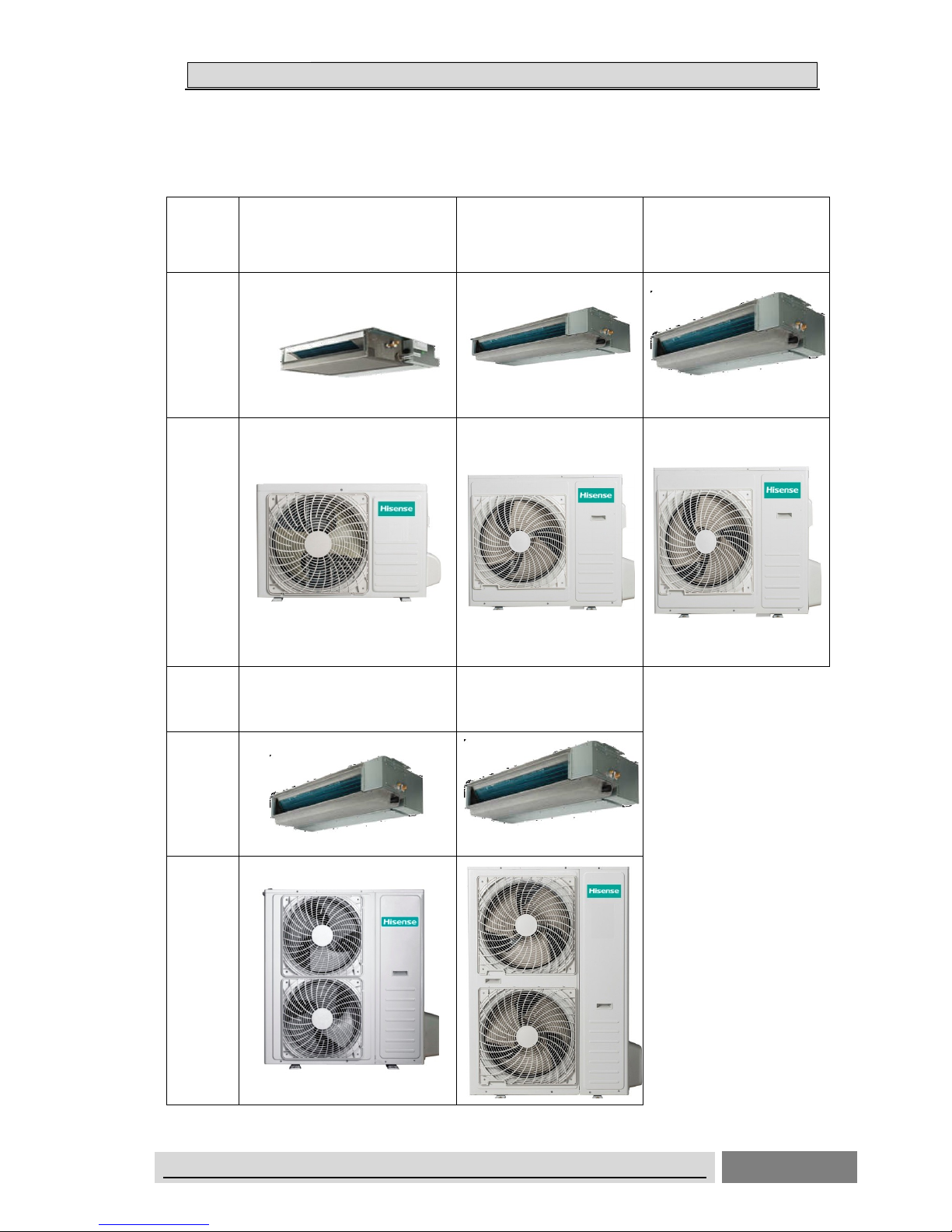
1-4 Product Picture
Duct Type
Model
AUD-18HX4SUNL
AUD-18HX4SUNL1
AUD-24HX4SZLH
AUD-24HX4SZLH1
AUD-36HX6SAHH
AUD-36HX6SAHH1
AUD-36HX6S1A1HH1
Indoor
Outdoor
Model AUD-48HX6SEHH1
AUD-48HX6SPHH
AUD-60HX6SPHH
AUD-60HX6SPHH1
Indoor
Outdoor
Page 11
11.. GGEENNEERRAAL
L
ON/OFF UNITARY AIR CONDITIONER TECHNICAL& SERVICE MANUAL V6.0 9
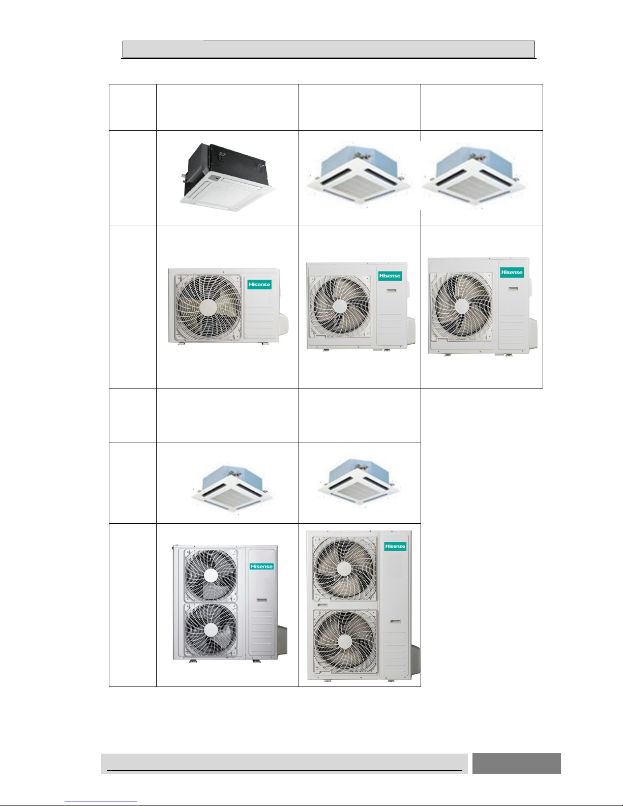
Cassette Type
Model
AUC-18HR4SUAA
AUC-18HR4SUAA1
AUC-24HR4SZGA
AUC-24HR4SZGA1
AUC-36HR6SAGA
AUC-36HR6SAGA1
AUC-36HR6S1AGA1
Indoor
Outdoor
Model AUC-48HR6SEHA1
AUC-48HR6SPHA
AUC-60HR6SPHA
AUC-60HR6SPHA1
Indoor
Outdoor
Page 12
11.. GGEENNEERRAAL
L
ON/OFF UNITARY AIR CONDITIONER TECHNICAL& SERVICE MANUAL V6.0 10
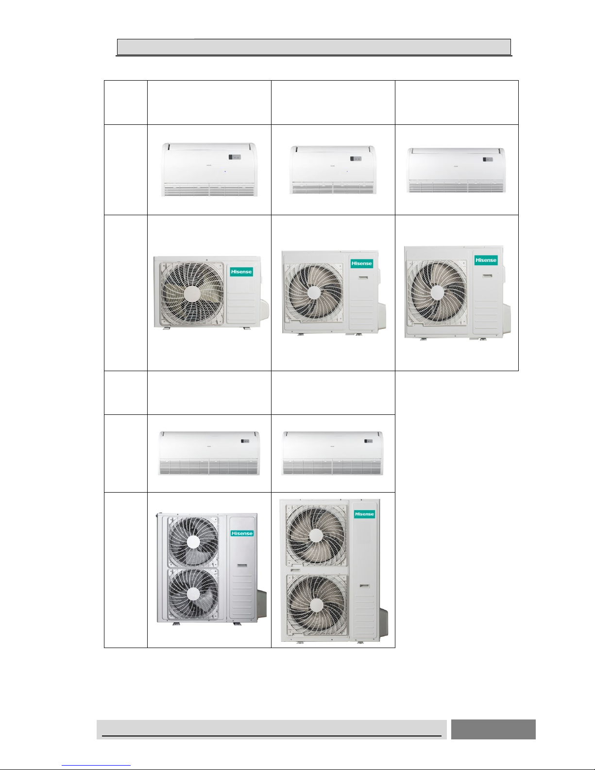
Ceiling&Floor Type
Model
AUV-18HR4SUA
AUV-18HR4SUA1
AUV-24HR4SZA
AUV-24HR4SZA1
AUV-36HR6SAB
AUV-36HR6SAB1
AUV-36HR6S1AB1
Indoor
Outdoor
Model AUV-48HR6SEC1
AUV-48HR6SPC
AUV-60HR6SPC
AUV-60HR6SPC1
Indoor
Outdoor
Page 13
11.. GGEENNEERRAAL
L
ON/OFF UNITARY AIR CONDITIONER TECHNICAL& SERVICE MANUAL V6.0 11
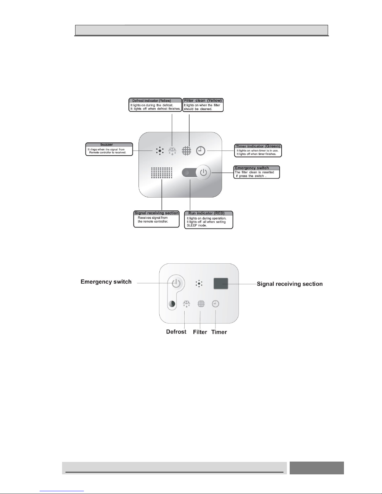
DISPLAY PANEL
Cassette Type
18k
24K,36K,48K,60K
Page 14
11.. GGEENNEERRAAL
L
ON/OFF UNITARY AIR CONDITIONER TECHNICAL& SERVICE MANUAL V6.0 12
Ceiling&Floor type
Page 15
22.. SSPPEECCIIFFIICCAATTIIOONNS
S
ON/OFF UNITARY AIR CONDITIONER TECHNICAL& SERVICE MANUAL V6.0 13
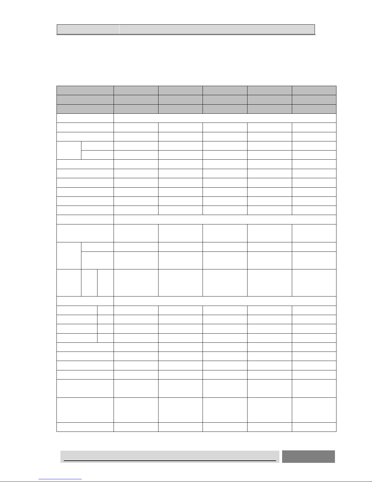
2. Specifications
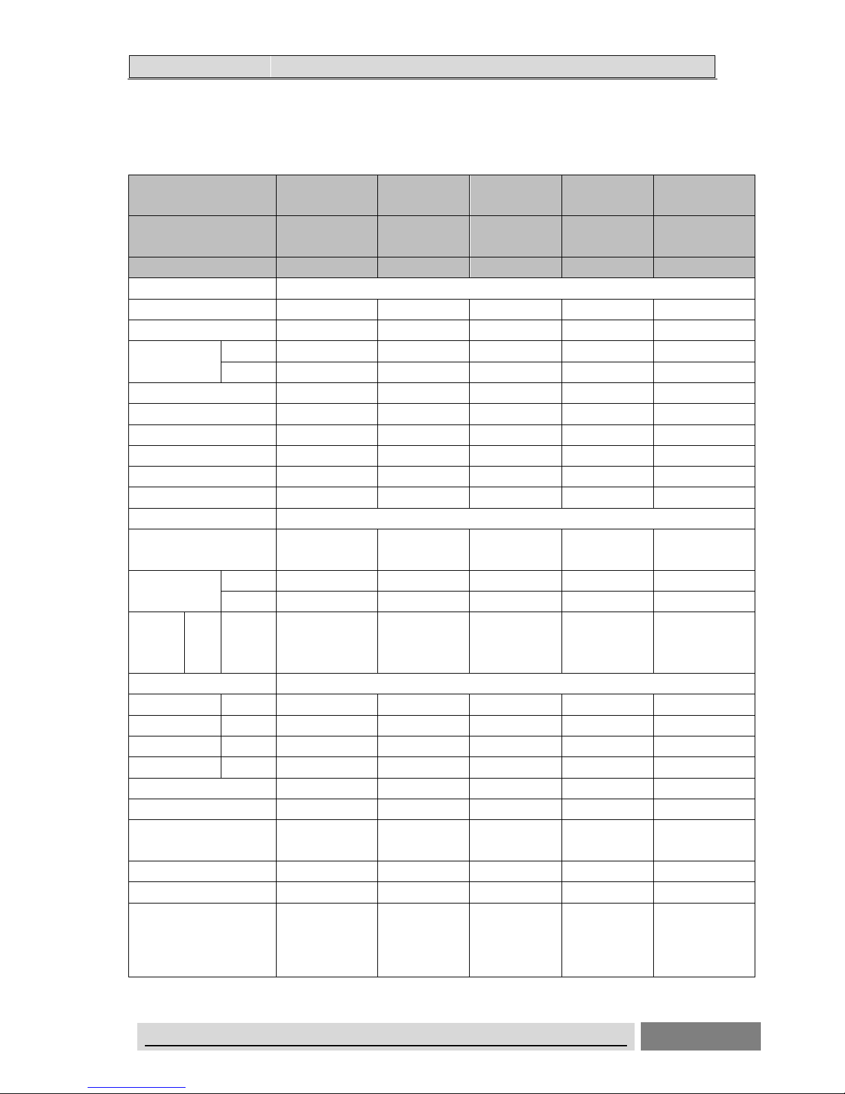
2.1Duct Type
On/Off Unitary Indoor Unit
AUD-18HX4SUNL AUD-24HX4SZLH AUD-36HX6SAHH AUD-48HX6SPHH AUD-60HX6SPHH
Indoor model: AUD-18HX4SNL AUD-24HX4SLH AUD-36HX4SHH AUD-48HX4SHH AUD-60HX4SHH
Outdoor model: AUW-18H4SU AUW-24H4SZ AUW-36H6SA AUW-48H6SP AUW-60H6SP
Performance
Cooling Capacity (W) 5000 7400 10200 14000 16000
Heating Capacity (W) 5500 7900 11250 15000 17500
Rated
Input (w)
Cooling 1550 2450 3625 4651 5694
Heating 1600 2190 3295 4532 5814
Air Circulation (m3/h) 710 1100 1800 2000 2000
EER for Cooling (w/w) 3.23 3.02 2.81 3.01 2.81
Energy Class A B C B C
COP for Heating (w/w) 3.44 3.61 3.41 3.31 3.01
Energy Class B A B C D
ESP (Pa) 10(30) 50(80) 50(80) 80(120) 80(120)
Power Supply
Volt/Phase/Hz
220-240V~/1P/50
Hz
220-240V~/1P/50
Hz
220-240V~/1P/50
Hz
220-240V~/1P/50
Hz
220-240V~/1P/50
Hz
Rated
Current
(A)
Cooling 7.1 11.5 6.5 8.8 10.0
Heating 7.3 11.0 6.1 8.6 10.3
Noise
Level
(dB (A))
Indoor
Unit
H/M/
L
37/35/32 40/38/36 40/38/36 46/44/42 46/44/42
Piping
Diameter(Liquid) Inch 1/4 3/8 3/8 3/8 3/8
Diameter(Gas) Inch 1/2 5/8 5/8 3/4 3/4
Max Length m 20 30 30 50 50
Max Height m 15 15 20 30 30
System
Compressor type Rotary Rotary SCROLL SCROLL SCROLL
Compressor MFG GMCC GMCC SANYO SANYO SANYO
Expansion Device capillary capillary capillary CAPILLARY CAPILLARY
Evaporator
Copper tube and
Aluminum Fin
Copper tube and
Aluminum Fin
Copper tube and
Aluminum Fin
Copper tube and
Aluminum Fin
Copper tube and
Aluminum Fin
Condenser
Copper tube and
Aluminum Fin
Copper tube and
Aluminum Fin
Copper tube and
Aluminum Fin
Copper tube and
Aluminum Fin
Copper tube and
Aluminum Fin
Other
Page 16
22.. SSPPEECCIIFFIICCAATTIIOONNS
S
ON/OFF UNITARY AIR CONDITIONER TECHNICAL& SERVICE MANUAL V6.0 14
AUD-18HX4SUNL AUD-24HX4SZLH AUD-36HX6SAHH AUD-48HX6SPHH AUD-60HX6SPHH
Indoor model: AUD-18HX4SNL AUD-24HX4SLH AUD-36HX4SHH AUD-48HX4SHH AUD-60HX4SHH
Outdoor model: AUW-18H4SU AUW-24H4SZ AUW-36H6SA AUW-48H6SP AUW-60H6SP
Dimensions
WxHxD
(mm)
Indoor
Unit
900×190×447 900×270 ×720 1386×350×800 1386×350×800 1386×350×800
Net Weight
(Kg)
Indoor
Unit
19
32
54 54 54
Packing
Dimensions
WxHxD
(mm)
Indoor
Unit
1070X236X580 1170X340X870 1550×410×940 1550×410×940 1550×410×940
Gross
Weight (Kg)
Indoor
Unit
24 37 62 62 62
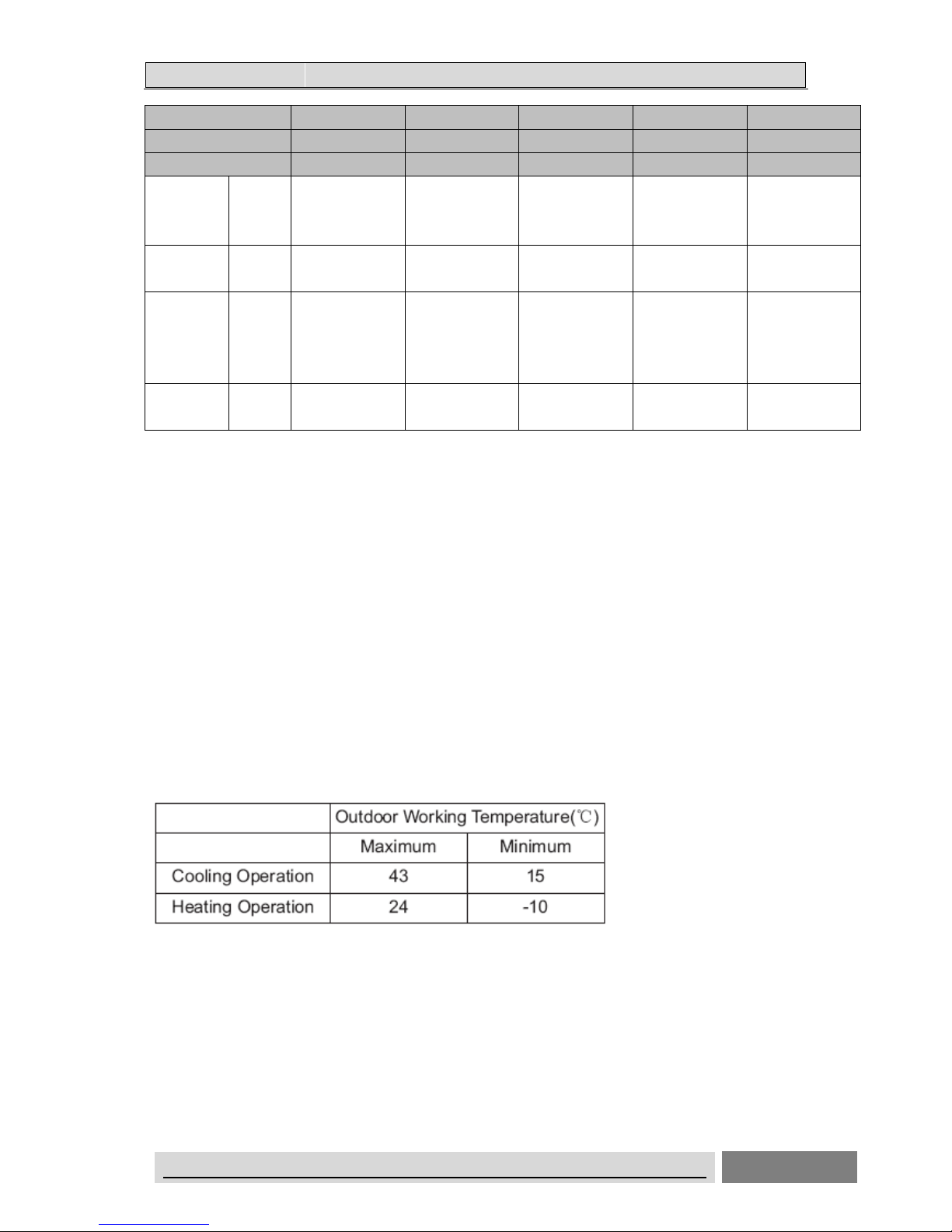
Test conditions:
Cooling : Indoor: DB27℃/ WB19℃ Outdoor: DB35℃/ WB24℃
Heating: Indoor: DB20℃/ WB15℃ Outdoor: DB7℃/ WB 6℃
Remarks:
1. The above design and specifications are subject to change without prior notice for product
improvement.
2.The values given in the table for noise level reflect the levels in anechoic chamber.
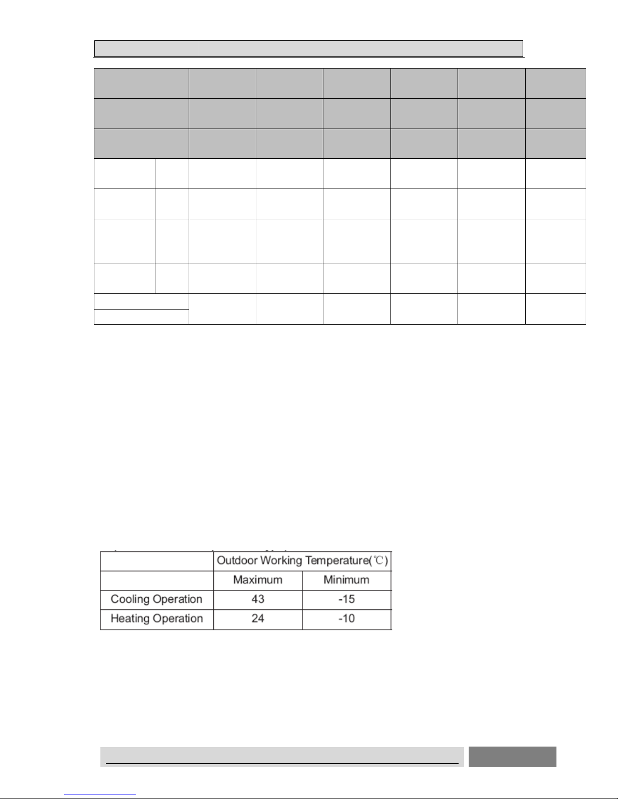
This heat pump air conditioner has been designed for the following temperatures.
Operate the heat pump air conditioner within this range.
Storage condition: Temperature -20~65℃
Humidity 30%~80%
Page 17
22.. SSPPEECCIIFFIICCAATTIIOONNS
S
ON/OFF UNITARY AIR CONDITIONER TECHNICAL& SERVICE MANUAL V6.0 15
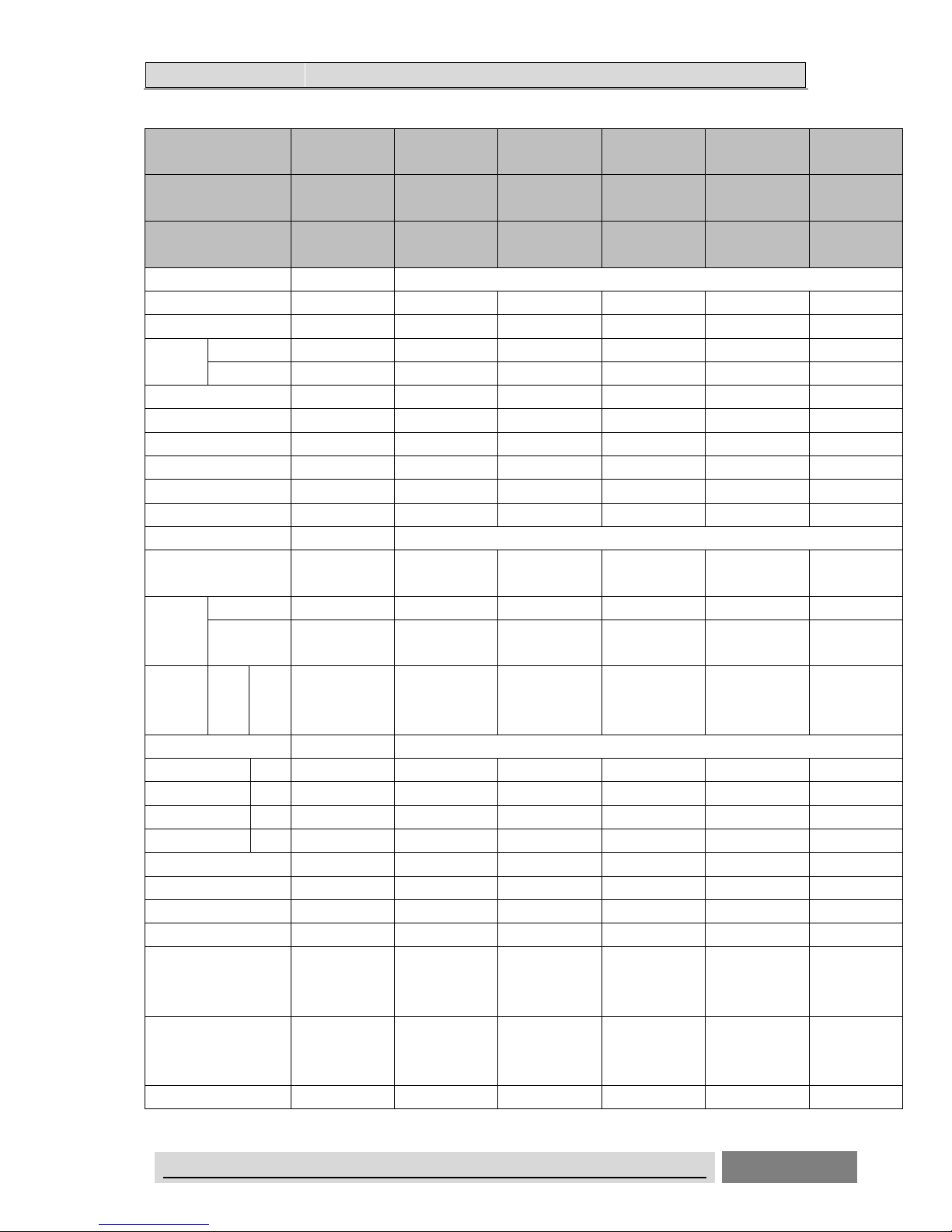
On/Off Unitary Indoor Unit (Low temp.)
AUD-18HX4SU
NL1
AUD-24HX4SZL
H1
AUD-36HX6SA
HH1
AUD-36HX6S1A
1HH1
AUD-48HX6SE
HH1
AUD-60HX6S
PHH1
Indoor model:
AUD-18HX4SNL AUD-24HX4SLH AUD-36HX4SHH AUD-36HX4S1HH AUD-48HX4SHH AUD-60HX4S
HH
Outdoor model: AUW-18H4SU1 AUW-24H4SZ1 AUW-36H6SA1
AUW-36H6S1A
1
AUW-48H6SE1
AUW-60H6SP
1
Performance
Cooling Capacity (W) 5000 7400 10200 10200 14000 16000
Heating Capacity (W) 5500 7900 11250 11250 15000 17500
Rated
Input (w)
Cooling 1550 2450 3625 3625 4651 5694
Heating 1600 2190 3295 3295 4532 5814
Air Circulation (m3/h) 710 1100 1800 1800 2000 2000
EER for Cooling (w/w) 3.23 3.02 2.81 2.81 3.01 2.81
Energy Class A B C C B C
COP for Heating (w/w) 3.44 3.61 3.41 3.41 3.31 3.01
Energy Class B A B B C D
ESP (Pa) 10(30) 50(80) 50(80) 50(80) 80(120) 80(120)
Power Supply
Volt/Phase/Hz
220-240V~/1P/5
0Hz
220-240V~/1P/5
0Hz
220-240V~/1P/5
0Hz
220-240V~/1P/5
0Hz
220-240V~/1P/5
0Hz
220-240V~/1P
/50Hz
Rated
Current
(A)
Cooling 7.1 11.5 6.5 6.5 8.8 10.0
Heating 7.3 11.0 6.1 6.1 8.6 10.3
Noise
Level
(dB (A))
Indoor
Unit
H/M/
L
37/35/32 40/38/36 40/38/36 40/38/36 46/44/42 46/44/42
Piping
Diameter(Liquid) Inch 1/4 3/8 3/8 3/8 3/8 3/8
Diameter(Gas) Inch 1/2 5/8 5/8 5/8 3/4 3/4
Max Length m 20 30 30 30 50 50
Max Height m 15 15 20 20 30 30
System
Compressor type Rotary Rotary SCROLL Rotary Rotary Rotary
Compressor MFG GMCC GMCC SANYO Highly Highly Highly
Expansion Device capillary capillary capillary CAPILLARY CAPILLARY CAPILLARY
Evaporator
Copper tube and
Aluminum Fin
Copper tube and
Aluminum Fin
Copper tube and
Aluminum Fin
Copper tube and
Aluminum Fin
Copper tube and
Aluminum Fin
Copper tube
and Aluminum
Fin
Condenser
Copper tube and
Aluminum Fin
Copper tube and
Aluminum Fin
Copper tube and
Aluminum Fin
Copper tube and
Aluminum Fin
Copper tube and
Aluminum Fin
Copper tube
and Aluminum
Fin
Other
Page 18
22.. SSPPEECCIIFFIICCAATTIIOONNS
S
ON/OFF UNITARY AIR CONDITIONER TECHNICAL& SERVICE MANUAL V6.0 16
AUD-18HX4SU
NL1
AUD-24HX4SZL
H1
AUD-36HX6SA
HH1
AUD-36HX6S1A
1HH1
AUD-48HX6SE
HH1
AUD-60HX6S
PHH1
Indoor model:
AUD-18HX4SNL AUD-24HX4SLH AUD-36HX4SHH AUD-36HX4S1HH AUD-48HX4SHH AUD-60HX4S
HH
Outdoor model: AUW-18H4SU1 AUW-24H4SZ1 AUW-36H6SA1
AUW-36H6S1A
1
AUW-48H6SE1
AUW-60H6SP
1
Dimensions
WxHxD (mm)
Indoor
Unit
900×190×447 900×270 ×720 1386×350×800 1386×350×800 1386×350×800
1386×350×80
0
Net Weight
(Kg)
Indoor
Unit
19
32
54 54 54 54
Packing
Dimensions
WxHxD (mm)
Indoor
Unit
1070X236X580 1170X340X870 1550×410×940 1550×410×940 1550×410×940
1550×410×94
0
Gross Weight
(Kg)
Indoor
Unit
24 37 62 62 62 62
Loading Capacity
76/160/180 36/80/94 23/50/56 23/50/56 23/50/56 19/40/42
(20/40’/40’ HC)
Test conditions:
Cooling : Indoor: DB27℃/ WB19℃ Outdoor: DB35℃/ WB24℃
Heating: Indoor: DB20℃/ WB15℃ Outdoor: DB7℃/ WB 6℃
Remarks:
1.The above design and specifications are subject to change without prior notice for product
improvement.
2.The values given in the table for noise level reflect the levels in anechoic chamber.
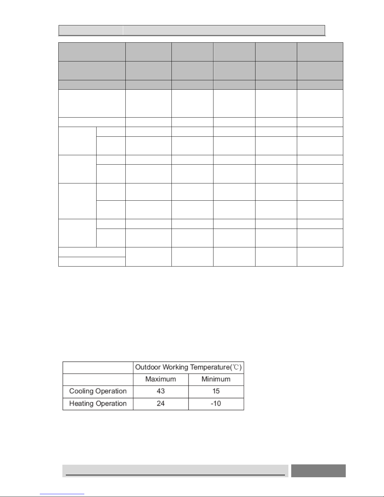
This heat pump air conditioner has been designed for the following temperatures.
Operate the heat pump air conditioner within this range.
Storage condition: Temperature -20~65℃
Humidity 30%~80%
Page 19
22.. SSPPEECCIIFFIICCAATTIIOONNS
S
ON/OFF UNITARY AIR CONDITIONER TECHNICAL& SERVICE MANUAL V6.0 17
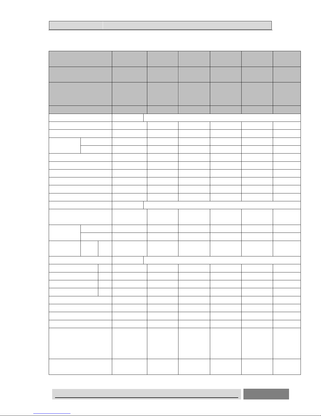
2.2 Cassette Type
On/Off Unitary Indoor Unit
AUC-18HR4SUAA AUC-24HR4SZ
GA
AUC-36HR6SA
GA
AUC-48HR6SP
HA
AUC-60HR6SPHA
Indoor model: AUC-18HR4SAA
AUC-24HR4SGA AUC-36HR4SGA AUC-48HR4SH
A
AUC-60HR4SHA
Outdoor model: AUW-18H4SU AUW-24H4SZ AUW-36H6SA AUW-48H6SP AUW-60H6SP
Performance
Cooling Capacity (W) 5000 7450 10000 14000 16000
Heating Capacity (W) 5500 7500 11000 14800 17500
Rated Input (w)
Cooling 1550 2320 3550 4650 5694
Heating 1550 2080 3225 4853 5814
Air Circulation (m3/h) 800 1100 1800 2000 2000
EER for Cooling (w/w) 3.23 3.21 2.81 3.01 2.81
Energy Class A A C B C
COP for Heating (w/w) 3.55 3.61 3.41 3.05 3.01
Energy Class B A B D D
ESP (Pa)
Power Supply
Volt/Phase/Hz
220-240V~/1P/50
Hz
220-240V~/1P/5
0Hz
220-240V~/1P/5
0Hz
220-240V~/1P/5
0Hz
220-240V~/1P/50
Hz
Rated Current
(A)
Cooling 7.1 10.8 6.0 8.9 10.0
Heating 7.1 10.0 5.7 9.3 10.3
Noise
Level
(dB (A))
Indoor
Unit
H/M/L 46/42/39 43/38/30 50/47/44 50/45/40 50/45/40
Piping
Diameter(Liquid) Inch 1/4 3/8 3/8 3/8 3/8
Diameter(Gas) Inch 1/2 5/8 5/8 3/4 3/4
Max Length m 20 30 30 50 50
Max Height m 15 15 20 30 30
System
Compressor type Rotary Rotary SCROLL SCROLL SCROLL
Compressor Model
No.
PA190M2CS-4K
TL
PA290G2CS-4
MUL1
C-SBN303H8D C-SBN373H8D C-SBN453H8D
Compressor MFG GMCC GMCC SANYO SANYO SANYO
Expansion Device capillary capillary capillary CAPILLARY CAPILLARY
Evaporator
Copper tube and
Aluminum Fin
Copper tube
and Aluminum
Fin
Copper tube
and Aluminum
Fin
Copper tube
and Aluminum
Fin
Copper tube and
Aluminum Fin
Page 20
22.. SSPPEECCIIFFIICCAATTIIOONNS
S
ON/OFF UNITARY AIR CONDITIONER TECHNICAL& SERVICE MANUAL V6.0 18
AUC-18HR4SUAA AUC-24HR4SZ
GA
AUC-36HR6SA
GA
AUC-48HR6SP
HA
AUC-60HR6SPHA
Indoor model: AUC-18HR4SAA
AUC-24HR4SGA AUC-36HR4SGA AUC-48HR4SH
A
AUC-60HR4SHA
Outdoor model: AUW-18H4SU AUW-24H4SZ AUW-36H6SA AUW-48H6SP AUW-60H6SP
Condenser
Copper tube and
Aluminum Fin
Copper tube
and Aluminum
Fin
Copper tube
and Aluminum
Fin
Copper tube
and Aluminum
Fin
Copper tube and
Aluminum Fin
Other
Dimensions
WxHxD (mm)
Panel 650x30x650 950x37x950 950x37x950 950x37x950 950x37x950
Indoor
Unit
650x270x570 840x248x840 840x248x840 840x298x840 840x298x840
Net Weight
(Kg)
Panel 2.4 6 6 6 6
Indoor
Unit
20 28 30 33 33
Packing
Dimensions
WxHxD (mm)
Panel 730x130x730 990x115x1010 990x115x1010 1010x115x990 1010x115x990
Indoor
Unit
770x310x750 930x290x930 930x290x930 930x340x930 930x340x930
Gross Weight
(Kg)
Panel 5 7.5 7.5 7.5 7.5
Indoor
Unit
27 34 36 39 39
Loading Capacity
56/115/130 43/90/104 32/66/77 23/48/53 23/48/53
(20/40’/40’ HC)
Test conditions:
Cooling : Indoor: DB27℃/ WB19℃ Outdoor: DB35℃/ WB24℃
Heating: Indoor: DB20℃/ WB15℃ Outdoor: DB7℃/ WB 6℃
Remarks:
1.The above design and specifications are subject to change without prior notice for product
improvement.
2.The values given in the table for noise level reflect the levels in anechoic chamber.
This heat pump air conditioner has been designed for the following temperatures.
Operate the heat pump air conditioner within this range.
Storage condition: Temperature -20~65℃
Humidity 30%~80%
Page 21
22.. SSPPEECCIIFFIICCAATTIIOONNS
S
ON/OFF UNITARY AIR CONDITIONER TECHNICAL& SERVICE MANUAL V6.0 19
On/Off Unitary Indoor Unit(Low Temp.)
AUC-18HR4SU
AA1
AUC-24HR4S
ZGA1
AUC-36HR6S
AGA1
AUC-36HR6S
1AGA1
AUC-48HR6S
EHA1
AUC-60HR6
SPHA1
Indoor model:
AUC-18HR4SAA AUC-24HR4S
GA
AUC-36HR4S
GA
AUC-36HR4S
GA
AUC-48HR4S
HA
AUC-60HR4
SHA
Outdoor model: AUW-18H4SU1 AUW-24H4SZ
1
AUW-36H6SA1 AUW-36H6S1
A1
AUW-48H6SE1 AUW-60H6
SP1
Panel: PE-BA-B29 PE-CA-B29 PE-CA-B29 PE-CA-B29 PE-CA-B29 PE-CA-B29
Performance
Cooling Capacity (W) 5000 7450 10000 10000 14000 16000
Heating Capacity (W) 5500 7500 11000 11000 14800 17500
Rated Input
(w)
Cooling 1550 2320 3550 3550 4650 5694
Heating 1550 2080 3225 3225 4853 5814
Air Circulation (m3/h) 800 1100 1800 1800 2000 2000
EER for Cooling (w/w) 3.23 3.21 2.81 2.82 3.01 2.81
Energy Class A A C C B C
COP for Heating (w/w) 3.55 3.61 3.41 3.41 3.05 3.01
Energy Class B A B B D D
ESP (Pa)
Power Supply
Volt/Phase/Hz
220-240V~/1P/5
0Hz
220-240V~/1P
/50Hz
220-240V~/1P
/50Hz
220-240V~/1P
/50Hz
220-240V~/1P
/50Hz
220-240V~/
1P/50Hz
Rated Current
(A)
Cooling 7.1 10.8 6.0 6.0 8.9 10.0
Heating 7.1 10.0 5.7 5.7 9.3 10.3
Noise Level
(dB (A))
Indoor
Unit
H/M/
L
46/42/39 43/38/30 50/47/44 50/47/44 50/45/40 50/45/40
Piping
Diameter(Liquid) Inch 1/4 3/8 3/8 3/8 3/8 3/8
Diameter(Gas) Inch 1/2 5/8 5/8 5/8 3/4 3/4
Max Length m 20 30 30 30 50 50
Max Height m 15 15 20 20 30 30
System
Compressor type Rotary Rotary SCROLL Rotary Rotary Rotary
Compressor MFG GMCC GMCC SANYO Highly Highly Highly
Expansion Device capillary capillary capillary CAPILLARY CAPILLARY CAPILLARY
Evaporator
Copper tube and
Aluminum Fin
Copper tube
and Aluminum
Fin
Copper tube
and Aluminum
Fin
Copper tube
and Aluminum
Fin
Copper tube
and Aluminum
Fin
Copper tube
and
Aluminum
Fin
Condenser
Copper tube and
Aluminum Fin
Copper tube
and Aluminum
Copper tube
and Aluminum
Copper tube
and Aluminum
Copper tube
and Aluminum
Copper tube
and
Page 22
22.. SSPPEECCIIFFIICCAATTIIOONNS
S
ON/OFF UNITARY AIR CONDITIONER TECHNICAL& SERVICE MANUAL V6.0 20
AUC-18HR4SU
AA1
AUC-24HR4S
ZGA1
AUC-36HR6S
AGA1
AUC-36HR6S
1AGA1
AUC-48HR6S
EHA1
AUC-60HR6
SPHA1
Indoor model:
AUC-18HR4SAA AUC-24HR4S
GA
AUC-36HR4S
GA
AUC-36HR4S
GA
AUC-48HR4S
HA
AUC-60HR4
SHA
Outdoor model: AUW-18H4SU1 AUW-24H4SZ
1
AUW-36H6SA1 AUW-36H6S1
A1
AUW-48H6SE1 AUW-60H6
SP1
Panel: PE-BA-B29 PE-CA-B29 PE-CA-B29 PE-CA-B29 PE-CA-B29 PE-CA-B29
Fin Fin Fin Fin Aluminum
Fin
Other
Dimension
s WxHxD
(mm)
Panel 650x30x650 950x37x950 950x37x950 950x37x950 950x37x950 950x37x950
Indoor Unit 650x270x570 840x248x840 840x248x840 840x248x840 840x298x840
840x298x84
0
Net Weight
(Kg)
Panel 2.4 6 6 6 6 6
Indoor Unit 20 28 30 30 33 33
Packing
Dimension
s WxHxD
(mm)
Panel 730x130x730 990x115x1010 990x115x1010 990x115x1010 1010x115x990
1010x115x9
90
Indoor Unit 770x310x750 930x290x930 930x290x930 930x290x930 930x340x930
930x340x93
0
Gross
Weight
(Kg)
Panel 5 10 10 10 10 10
Indoor Unit 27 34 36 36 39 39
Test conditions:
Cooling : Indoor: DB27℃/ WB19℃ Outdoor: DB35℃/ WB24℃
Heating: Indoor: DB20℃/ WB15℃ Outdoor: DB7℃/ WB 6℃
Remarks:
1.The above design and specifications are subject to change without prior notice for product
improvement.
2.The values given in the table for noise level reflect the levels in anechoic chamber.
This heat pump air conditioner has been designed for the following temperatures.
Operate the heat pump air conditioner within this range.
Storage condition: Temperature -20~65℃
Humidity 30%~80%
Page 23

22.. SSPPEECCIIFFIICCAATTIIOONNS
S
ON/OFF UNITARY AIR CONDITIONER TECHNICAL& SERVICE MANUAL V6.0 21
2.3 Ceiling&Floor type
On/Off Unitary Indoor Unit
AUV-18HR4SUA AUV-24HR4S
ZA
AUV-36HR6S
AB
AUV-48HR6SPC AUV-60HR6S
PC
Indoor model: AUV-18HR4SA
AUV-24HR4SA AUV-36HR4S
B
AUV-48HR4SC
AUV-60HR4S
C
Outdoor model: AUW-18H4SU AUW-24H4SZ AUW-36H6SA AUW-48H6SP AUW-60H6SP
Performance
Cooling Capacity (W) 5000 7700 10200 14000 16000
Heating Capacity (W) 5500 7900 12000 16000 18000
Rated Input (w)
Cooling 1550 2400 3625 4651 5694
Heating 1520 2190 3510 4532 5814
Air Circulation (m3/h) 800 1100 1800 2000 2000
EER for Cooling (w/w) 3.23 3.21 2.81 3.01 2.81
Energy Class A A C B C
COP for Heating (w/w) 3.62 3.61 3.42 3.53 3.10
Energy Class A A B B D
Power Supply
Volt/Phase/Hz
220-240V~/1P/5
0Hz
220-240V~/1P
/50Hz
220-240V~/1P
/50Hz
220-240V~/1P/5
0Hz
220-240V~/1P
/50Hz
Rated Current (A)
Cooling 7.1 11.2 6.7 8.8 10.0
Heating 7.0 11.0 6.5 8.6 10.3
Noise Level (dB (A))
Indoor
Unit
H/M/
L
41/38/35 52/48/45 53/52/50 53/52/50 53/52/50
Piping
Diameter(Liquid) Inch 1/4 3/8 3/8 3/8 3/8
Diameter(Gas) Inch 1/2 5/8 5/8 3/4 3/4
Max Length m 20 30 30 50 50
Max Height m 15 15 20 30 30
System
Compressor type Rotary Rotary SCROLL SCROLL SCROLL
Compressor MFG GMCC GMCC SANYO SANYO SANYO
Expansion Device capillary capillary capillary CAPILLARY CAPILLARY
Evaporator
Copper tube and
Aluminum Fin
Copper tube
and Aluminum
Fin
Copper tube
and Aluminum
Fin
Copper tube and
Aluminum Fin
Copper tube
and Aluminum
Fin
Condenser
Copper tube and
Aluminum Fin
Copper tube
and Aluminum
Fin
Copper tube
and Aluminum
Fin
Copper tube and
Aluminum Fin
Copper tube
and Aluminum
Fin
Other
Page 24
22.. SSPPEECCIIFFIICCAATTIIOONNS
S
ON/OFF UNITARY AIR CONDITIONER TECHNICAL& SERVICE MANUAL V6.0 22
AUV-18HR4SUA AUV-24HR4S
ZA
AUV-36HR6S
AB
AUV-48HR6SPC AUV-60HR6S
PC
Indoor model: AUV-18HR4SA
AUV-24HR4SA AUV-36HR4S
B
AUV-48HR4SC
AUV-60HR4S
C
Outdoor model: AUW-18H4SU AUW-24H4SZ AUW-36H6SA AUW-48H6SP AUW-60H6SP
Dimensions WxHxD
(mm)
Indoor Unit 990x680x230 990x680x230 1285x680x230 1580x680x230 1580x680x230
Net Weight (Kg) Indoor Unit 27
28
37 46 46
Packing Dimensions
WxHxD (mm)
Indoor Unit 1100x820x350 1100x820x350 1400x820x350 1690x820x350 1690x820x350
Gross Weight (Kg) Indoor Unit 33 34 44 54 54
Loading Capacity
55/116/122 45/99/105 33/67/74 22/47/50 22/47/50
(20/40’/40’ HC)
Test conditions:
Cooling : Indoor: DB27℃/ WB19℃ Outdoor: DB35℃/ WB24℃
Heating: Indoor: DB20℃/ WB15℃ Outdoor: DB7℃/ WB 6℃
Remarks:
1.The above design and specifications are subject to change without prior notice for product
improvement.
2.The values given in the table for noise level reflect the levels in anechoic chamber.
This heat pump air conditioner has been designed for the following temperatures.
Operate the heat pump air conditioner within this range.
Storage condition: Temperature -20~65℃
Humidity 30%~80%
Page 25
22.. SSPPEECCIIFFIICCAATTIIOONNS
S
ON/OFF UNITARY AIR CONDITIONER TECHNICAL& SERVICE MANUAL V6.0 23
On/Off Unitary Indoor Unit(Low Temp.)
AUV-18HR4S
UA1
AUV-24HR4S
ZA1
AUV-36HR6S
AB1
AUV-36HR6S
1AB1
AUV-48HR6S
EC1
AUV-60HR6S
PC1
Indoor model:
AUV-18HR4SA AUV-24HR4SA AUV-36HR4SB AUV-36HR4SB AUV-48HR4SC AUV-60HR4S
C
Outdoor model:
AUW-18H4SU1 AUW-24H4SZ1 AUW-36H6SA1 AUW-36H6S1
A1
AUW-48H6SE1 AUW-60H6SP
1
Performance
Cooling Capacity (W) 5000 7700 10200 10200 14000 16000
Heating Capacity (W) 5500 7900 12000 12000 16000 18000
Rated
Input (w)
Cooling 1550 2400 3625 3625 4651 5694
Heating 1520 2190 3510 3510 4532 5814
Air Circulation (m3/h) 800 1100 1800 1800 2000 2000
EER for Cooling (w/w) 3.23 3.21 2.81 2.81 3.01 2.81
Energy Class A A C C B C
COP for Heating (w/w) 3.62 3.61 3.42 3.42 3.53 3.10
Energy Class A A B B B D
Power Supply
Volt/Phase/Hz
220-240V~/1P
/50Hz
220-240V~/1P
/50Hz
220-240V~/1P
/50Hz
220-240V~/1P
/50Hz
220-240V~/1P
/50Hz
220-240V~/1P
/50Hz
Rated
Current
(A)
Cooling 7.1 11.2 6.7 6.7 8.8 10.0
Heating 7.0 11.0 6.5 6.5 8.6 10.3
Noise
Level
(dB (A))
Indoor
Unit
H/M/L 41/38/35 52/48/45 53/52/50 53/52/50 53/52/50 53/52/50
Piping
Diameter(Liquid) Inch 1/4 3/8 3/8 3/8 3/8 3/8
Diameter(Gas) Inch 1/2 5/8 5/8 5/8 3/4 3/4
Max Length m 20 30 30 30 50 50
Max Height m 15 15 20 20 30 30
System
Compressor type Rotary Rotary SCROLL Rotary Rotary Rotary
Compressor MFG GMCC GMCC SANYO Highly Highly Highly
Expansion Device capillary capillary capillary CAPILLARY CAPILLARY CAPILLARY
Evaporator
Copper tube
and Aluminum
Fin
Copper tube
and Aluminum
Fin
Copper tube
and Aluminum
Fin
Copper tube
and Aluminum
Fin
Copper tube
and Aluminum
Fin
Copper tube
and Aluminum
Fin
Condenser
Copper tube
and Aluminum
Fin
Copper tube
and Aluminum
Fin
Copper tube
and Aluminum
Fin
Copper tube
and Aluminum
Fin
Copper tube
and Aluminum
Fin
Copper tube
and Aluminum
Fin
Other
Page 26
22.. SSPPEECCIIFFIICCAATTIIOONNS
S
ON/OFF UNITARY AIR CONDITIONER TECHNICAL& SERVICE MANUAL V6.0 24
AUV-18HR4S
UA1
AUV-24HR4S
ZA1
AUV-36HR6S
AB1
AUV-36HR6S
1AB1
AUV-48HR6S
EC1
AUV-60HR6S
PC1
Indoor model:
AUV-18HR4SA AUV-24HR4SA AUV-36HR4SB AUV-36HR4SB AUV-48HR4SC AUV-60HR4S
C
Outdoor model:
AUW-18H4SU1 AUW-24H4SZ1 AUW-36H6SA1 AUW-36H6S1
A1
AUW-48H6SE1 AUW-60H6SP
1
Dimensions
WxHxD (mm)
Indoor Unit 990x680x230 990x680x230 1285x680x230 1285x680x230 1580x680x230 1580x680x230
Net Weight
(Kg)
Indoor Unit 27
28
37 37 46 46
Packing
Dimensions
WxHxD (mm)
Indoor Unit 1100x820x350 1100x820x350 1400x820x350 1400x820x350 1690x820x350 1690x820x350
Gross Weight
(Kg)
Indoor Unit 33 34 44 44 54 54
Test conditions:
Cooling : Indoor: DB27℃/ WB19℃ Outdoor: DB35℃/ WB24℃
Heating: Indoor: DB20℃/ WB15℃ Outdoor: DB7℃/ WB 6℃
Remarks:
1.The above design and specifications are subject to change without prior notice for product
improvement.
2.The values given in the table for noise level reflect the levels in anechoic chamber.
This heat pump air conditioner has been designed for the following temperatures.
Operate the heat pump air conditioner within this range.
Storage condition: Temperature -20~65℃
Humidity 30%~80%
Page 27

22.. SSPPEECCIIFFIICCAATTIIOONNS
S
ON/OFF UNITARY AIR CONDITIONER TECHNICAL& SERVICE MANUAL V6.0 25
2.5 On/Off Unitary Universal Outdoor Unit
Outdoor Unit:
AUW-18H4S
U
AUW-24H4SZ
AUW-36H6
SA
AUW-48H6SP AUW-60H6SP
Performance
Power Supply
Volt/Phase/Hz
220-240V~/1P
/50Hz
220-240V~/1P
/50Hz
380~415V~/
3Ph/50Hz
380~415V~/3
Ph/50Hz
380~415V~/3Ph/50
Hz
Rated Input (w)
Cooling
RFT IDU
LABEL
RFT IDU
LABEL
RFT IDU
LABEL
RFT IDU
LABEL
RFT IDU LABEL
Heating
RFT IDU
LABEL
RFT IDU
LABEL
RFT IDU
LABEL
RFT IDU
LABEL
RFT IDU LABEL
Rated Current (A)
Cooling
RFT IDU
LABEL
RFT IDU
LABEL
RFT IDU
LABEL
RFT IDU
LABEL
RFT IDU LABEL
Heating
RFT IDU
LABEL
RFT IDU
LABEL
RFT IDU
LABEL
RFT IDU
LABEL
RFT IDU LABEL
Air Circulation (m3 Max) 2700 3200 3500 6000 6000
Noise Level (dB (A)) 52 56 57 57 55
Piping
Diameter(Liquid)
Inch 1/4 3/8 3/8 3/8 3/8
Diameter(Gas)
Inch 1/2 5/8 5/8 3/4 3/4
Max Length
m 20 30 30 50 50
Max Height m 15 15 20 30 30
Refrigerant charge volume
g
1200 1650 2100 3100
3400
Dimensions WxHxD (mm)
Net Dimensions WxHxD
(mm)
Outdoor Unit 800×550×260 900×640×300
950x840x34
0
950x1386x340 950x1386x340
Net Weight (Kg) Outdoor Unit 37 54 83 114 114
Packing Dimensions WxHxD
(mm)
Outdoor Unit 930×620×360
1050×700×400 1110x980x4
60
1110x1530x46
0 1110x1530x460
Gross Weight (Kg) Outdoor Unit 40 60 91 124 124
Page 28
22.. SSPPEECCIIFFIICCAATTIIOONNS
S
ON/OFF UNITARY AIR CONDITIONER TECHNICAL& SERVICE MANUAL V6.0 26
Outdoor Unit: AUW-18H4SU1 AUW-24H4SZ1 AUW-36H6S1A1
AUW-48H
6SE1
AUW-60H6SP
1
Performance
Power Supply
Volt/Phase/Hz
220-240V~/1P/5
0Hz
220-240V~/1P/5
0Hz
380~415V~/3Ph/5
0Hz
380-415V
~/3Ph/50H
z
380-415V~/3P
h/50Hz
Rated Input (w)
Cooling RFT IDU LABEL RFT IDU LABEL RFT IDU LABEL
RFT IDU
LABEL
RFT IDU
LABEL
Heating RFT IDU LABEL RFT IDU LABEL RFT IDU LABEL
RFT IDU
LABEL
RFT IDU
LABEL
Rated Current (A)
Cooling RFT IDU LABEL RFT IDU LABEL RFT IDU LABEL
RFT IDU
LABEL
RFT IDU
LABEL
Heating RFT IDU LABEL RFT IDU LABEL RFT IDU LABEL
RFT IDU
LABEL
RFT IDU
LABEL
Air Circulation (m3 Max) 2700 3200 3500 5000 6000
Noise Level (dB (A)) 52 56 59 55 58
Piping
Diameter(Liquid) Inch 1/4 3/8 3/8 3/8 3/8
Diameter(Gas) Inch 1/2 5/8 5/8 3/4 3/4
Max Length m 20 30 30 50 50
Max Height m 15 15 20 30 30
Refrigerant charge
volume g
1200 1650 2300 2400
3100
Dimensions WxHxD (mm)
Net Dimensions WxHxD
(mm)
Outdoor
Unit
800×550×260 900×640×300 950x840x340
950x1050
x340
950x1386x340
Net Weight (Kg)
Outdoor
Unit
37 54 68 96 106
Packing Dimensions WxHxD
(mm)
Outdoor
Unit
930×620×360 1050×700×400 1110x980x460
1110x120
0x460
1110x1530x46
0
Gross Weight (Kg)
Outdoor
Unit
40 60 76
103 116
Page 29
33.. OOUUTTLLIINNEESS AANNDD DDIIMMEENNSSIIOONNSS
ON/OFF UNITARY AIR CONDITIONER TECHNICAL& SERVICE MANUAL V6.0
27
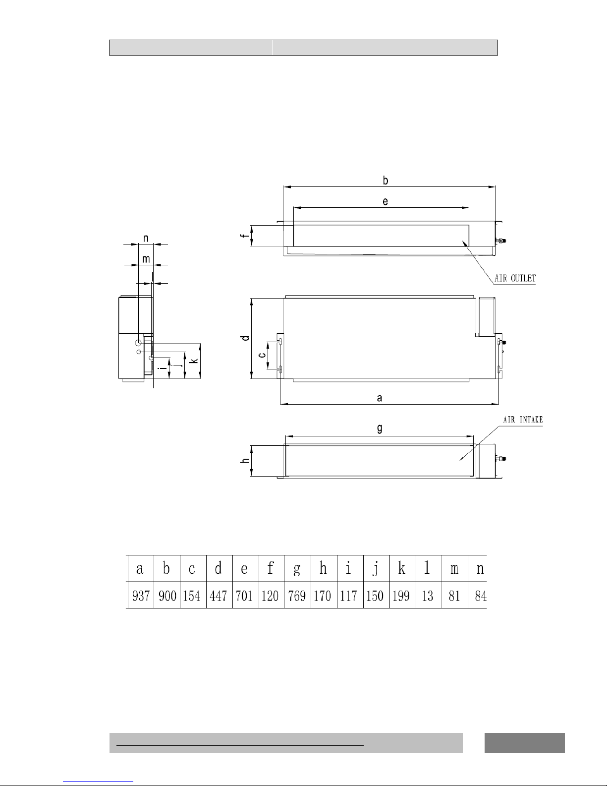
3.1 INDOOR UNIT
Duct Type
18K
Page 30
33.. OOUUTTLLIINNEESS AANNDD DDIIMMEENNSSIIOONNSS
ON/OFF UNITARY AIR CONDITIONER TECHNICAL& SERVICE MANUAL V6.0
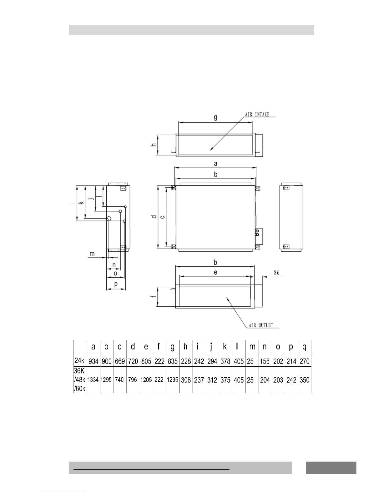
28
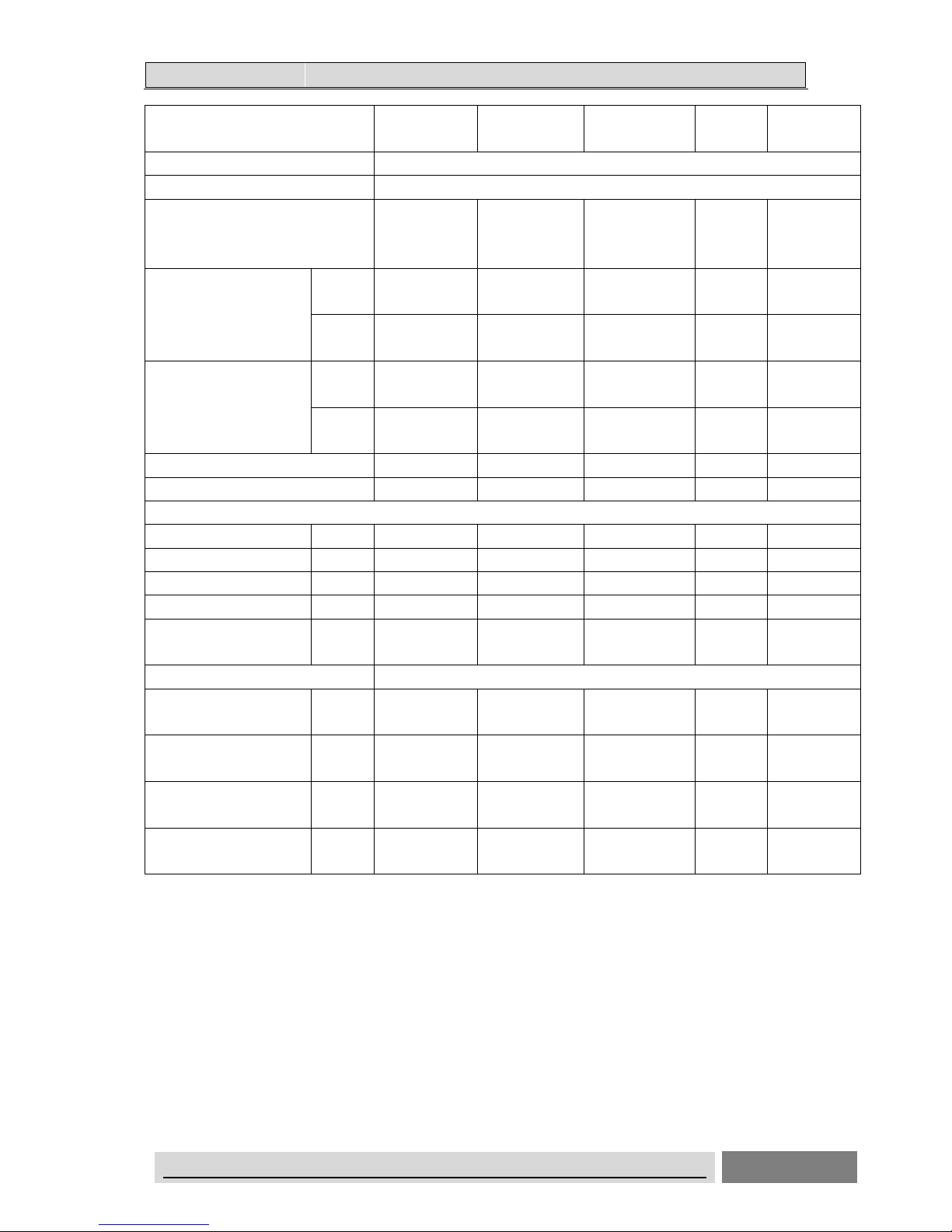
24K/36K/48K/60K
Page 31

33.. OOUUTTLLIINNEESS AANNDD DDIIMMEENNSSIIOONNSS
ON/OFF UNITARY AIR CONDITIONER TECHNICAL& SERVICE MANUAL V6.0
29
Cassette Type
18k
Page 32

33.. OOUUTTLLIINNEESS AANNDD DDIIMMEENNSSIIOONNSS
ON/OFF UNITARY AIR CONDITIONER TECHNICAL& SERVICE MANUAL V6.0
30
Page 33

33.. OOUUTTLLIINNEESS AANNDD DDIIMMEENNSSIIOONNSS
ON/OFF UNITARY AIR CONDITIONER TECHNICAL& SERVICE MANUAL V6.0
31
24K,36K,48K,60K
Page 34

33.. OOUUTTLLIINNEESS AANNDD DDIIMMEENNSSIIOONNSS
ON/OFF UNITARY AIR CONDITIONER TECHNICAL& SERVICE MANUAL V6.0
32
Page 35

33.. OOUUTTLLIINNEESS AANNDD DDIIMMEENNSSIIOONNSS
ON/OFF UNITARY AIR CONDITIONER TECHNICAL& SERVICE MANUAL V6.0
33
Ceiling&Floor Type
Page 36

33.. OOUUTTLLIINNEESS AANNDD DDIIMMEENNSSIIOONNSS
ON/OFF UNITARY AIR CONDITIONER TECHNICAL& SERVICE MANUAL V6.0
34
3-2.OUTDOOR
18K
Page 37

33.. OOUUTTLLIINNEESS AANNDD DDIIMMEENNSSIIOONNSS
ON/OFF UNITARY AIR CONDITIONER TECHNICAL& SERVICE MANUAL V6.0
35
24K
Page 38

33.. OOUUTTLLIINNEESS AANNDD DDIIMMEENNSSIIOONNSS
ON/OFF UNITARY AIR CONDITIONER TECHNICAL& SERVICE MANUAL V6.0
36
36K
Page 39

33.. OOUUTTLLIINNEESS AANNDD DDIIMMEENNSSIIOONNSS
ON/OFF UNITARY AIR CONDITIONER TECHNICAL& SERVICE MANUAL V6.0
37
48K
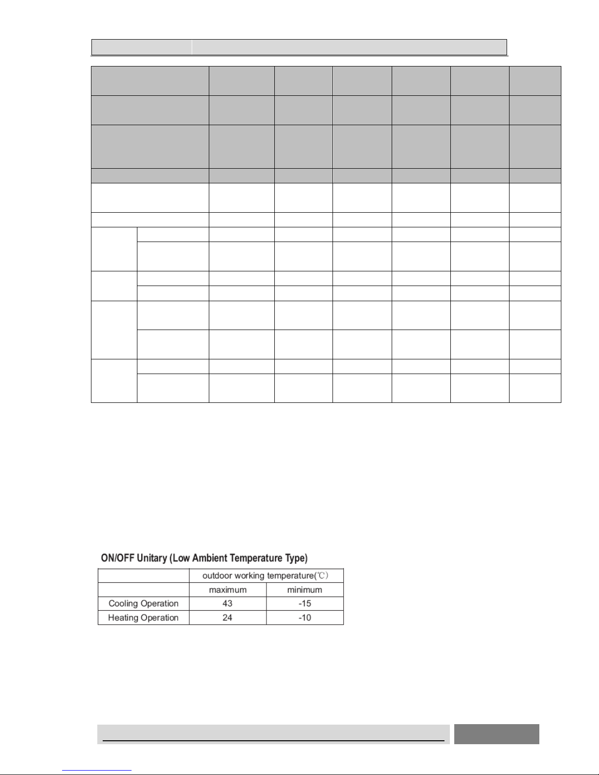
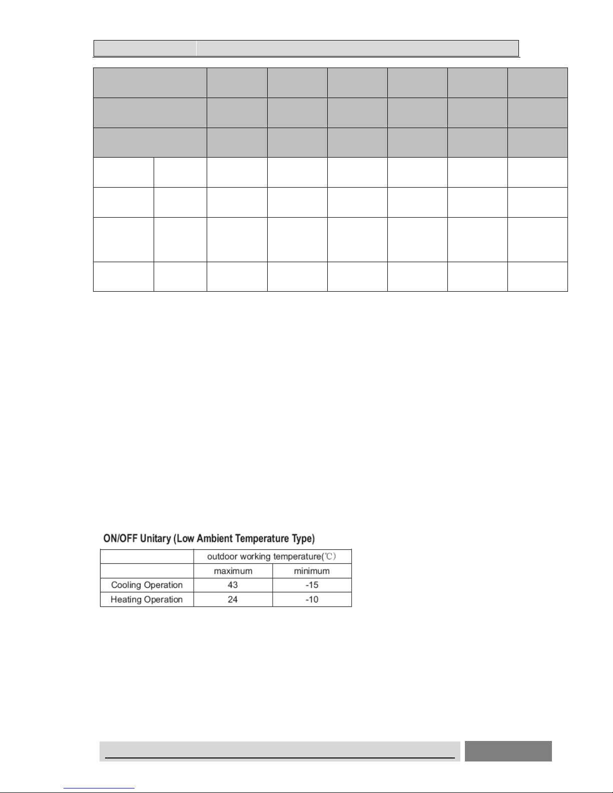
(Low Ambient Temperature Type )
Page 40

33.. OOUUTTLLIINNEESS AANNDD DDIIMMEENNSSIIOONNSS
ON/OFF UNITARY AIR CONDITIONER TECHNICAL& SERVICE MANUAL V6.0
38
60K
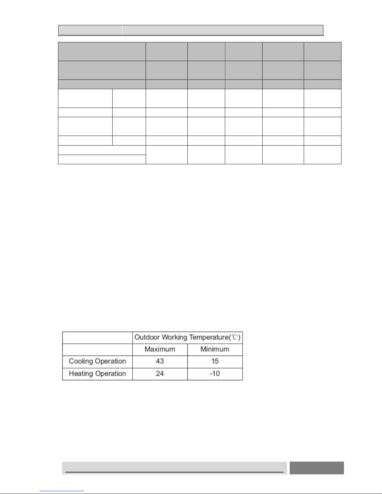
48K(Ordinary Type)
Page 41

44.. DDIIAAGGRRAAMM&&DDAATTAA
UNITARY AIR CONDITIONER TECHNICAL& SERVICE MANUAL V6.0
39
4.Piping Diagrams& Data
4.1 Piping Diagrams
18K
Indoor heat exchanger
Check Valve
Indoor
Outdoor
Stop Valve
Coil
temperature
sensor
Ambient
temperature
sensor
4-Way Valve
Coil
temperature
sensor
Outdoor heat exchanger
Compressor
Bypass Capillary
strainer
Bypass Capillary
strainer
Ambient
temperature
sensor
COOLING CYCLE
HEATING CYCLE
24K
Indoor heat exchanger
Check Valve
Indoor
Outdoor
Stop Valve
Coil
temperature
sensor
Ambient
temperature
sensor
Stop Valve
Discharge
temperature
sensor
4-Way Valve
Ambient
temperature
sensor
Coil
temperature
sensor
Outdoor heat
exchanger
Compressor
Bypass Capillary
strainer
Bypass Capillary
strainer
COOLING CYCLE
HEATING CYCLE
Page 42

44.. DDIIAAGGRRAAMM&&DDAATTAA
UNITARY AIR CONDITIONER TECHNICAL& SERVICE MANUAL V6.0
40
36K
Indoor heat exchanger
Check Valve
Indoor
Outdoor
Stop Valve
Coil
temperature
sensor
Accumulator
HP
Ambient
temperature
sensor
Stop Valve
Discharge
temperature
sensor
Discharge
Pressure
Switch
4-Way Valve
Ambient
temperature
sensor
Coil
temperature
sensor
Outdoor heat
exchanger
Compressor
Bypass Capillary
strainer
Bypass Capillary
strainer
COOLING CYCLE
HEATING CYCLE
48K(Low Ambient Temperature Type)
Indoor heat exchanger
Check Valve
Indoor
Outdoor
Stop Valve
Coil
temperature
sensor
Ambient
temperature
sensor
Stop Valve
Discharge
temperature
sensor
4-Way Valve
Ambient
temperature
sensor
Coil
temperature
sensor
Outdoor heat
exchanger
Compressor
Bypass Capillary
strainer
Bypass Capillary
strainer
HP
LP
Discharge
Pressure
Switch
Suction
Pressure
Switch
COOLING CYCLE
HEATING CYCLE
Page 43

44.. DDIIAAGGRRAAMM&&DDAATTAA
UNITARY AIR CONDITIONER TECHNICAL& SERVICE MANUAL V6.0
41
60k
(Low Ambient Temperature Type)
Indoor heat exchanger
Check Valve
Indoor
Outdoor
Stop Valve
Coil
temperature
sensor
Ambient
temperature
sensor
Stop Valve
Discharge
temperature
sensor
4-Way Valve
Ambient
temperature
sensor
Coil
temperature
sensor
Outdoor heat
exchanger
Compressor
Bypass Capillary
strainer
Bypass Capillary
strainer
HP
LP
Discharge
Pressure
Switch
Suction
Pressure
Switch
COOLING CYCLE
HEATING CYCLE
48K、60k(Ordinary Temperature Type)
Indoor heat exchange
Check Valve
Indoor
Outdoor
Stop Valve
Coil
temperature
sensor
Accumulator
HP
Ambient
temperature
sensor
Stop Valve
Discharge
temperature
sensor
Discharge
Pressure
Switch
4-Way Valve
Ambient
temperature
sensor
Coil
temperature
sensor
Outdoor heat exchange
Suction
Pressure
Switch
Compressor
Bypass Capillary
strainer
Bypass Capillary
strainer
LP
Page 44

44.. DDIIAAGGRRAAMM&&DDAATTAA
UNITARY AIR CONDITIONER TECHNICAL& SERVICE MANUAL V6.0
42
4.2MAX. Refrigerant pipe length and height difference:
*Do your best to reduce the pipe length. Long pipe may cause capacity of the indoor unit incline.
Outdoor unit precharged
Total refrigerant pipe length
0m~5m Exceed 5m
AUW-18H4SU
1200g 0g
Xg = 15g / m × (Total pipe length(m) -5)
AUW-24H4SZ
1650g 0g
Xg =35g / m × (Total pipe length(m) -5)
AUW-36H6SA
2300g 0g
AUW-48H6SP
3100g 0g
AUW-60H6SP
3300g 0g
Outdoor unit precharged
Total refrigerant pipe length
0m~5m Exceed 5m
AUW-18H4SU1
1200g 0g
Xg = 15g / m × (Total pipe length(m) -5)
AUW-24H4SZ1
1650g 0g
Xg =35g / m × (Total pipe length(m) -5)
AUD-36H6SA1
2300g 0g
AUD-36H6S1A1
2300g 0g
AUW-48H6SE1
2400g 0g
AUW-60H6SP1
3100g 0g
Page 45

44.. DDIIAAGGRRAAMM&&DDAATTAA
UNITARY AIR CONDITIONER TECHNICAL& SERVICE MANUAL V6.0
43
4.3ELECTRIC Diagrams
18K
24K
36K/48K/60K
Page 46

44.. DDIIAAGGRRAAMM&&DDAATTAA
UNITARY AIR CONDITIONER TECHNICAL& SERVICE MANUAL V6.0
44
Recommend Wire Size
Model
Capacity(Btu/h)
POWER SUPPLY
Power Source
Cable Size
(mm2)
Transmitting Cable
Size
(mm2)
18K 220-240V ~,50Hz 3×1.5 5×1.5
24K 220-240V ~,50Hz 3×2.5 4×1.5
36K 380-415V ~,3N~,50Hz 5×1.5 4×1.5
48K/60K 380-415V ~,3N~,50Hz 5×2.5 4×1.5
● Use an ELB (Electric Leakage Breaker). If not used, it will cause an electric shock or a
fire.
● Do not operate the system until all the check points have been cleared.
(A) Check to ensure that the insulution resistance is more than 1 megohm, by measuring
the
resistance between ground and the terminal of the electrical parts. If not, do not operate
the system until the electrical leakage is found and repaired.
(B) Check to ensure that the stop valves of the outdoor unit are fully opened and then start
the system.
● Pay attention to the following items while the system is running.
(A) Do not touch any of the parts by hand at the discharge gas side, since the compressor
chamber and the pipes at the discharge side are heated higher than 90℃.
(B) DO NOT PUSH THE BUTTON OF THE MAGNETIC SWITCH(ES). It will cause a
serious Accident.
NOTES:
1) Follow local codes and regulations when selecting field wires.
2) The wire sizes marked in the table are selected at the maxim current of the
unit according to the European Standard ,En60 335-1. Use the wires which are
not lighter than the ordinary tough rubber sheathed flexible cord (code
designation H05RN-F) or ordinary polychloroprene sheathed flexible
Page 47

44.. DDIIAAGGRRAAMM&&DDAATTAA
UNITARY AIR CONDITIONER TECHNICAL& SERVICE MANUAL V6.0
45
cord (code designation H05RN-F) .
3) Use a shielded cable for the transmitting circuit and connect it to ground .
4) In the case that power cables are connected in series, add each unit
maximum current and select wires below.
* in the case that current exceeds 63A, do not connect cables in series.
Page 48

44.. DDIIAAGGRRAAMM&&DDAATTAA
UNITARY AIR CONDITIONER TECHNICAL& SERVICE MANUAL V6.0
46
4-4Air flow and ESP Chart Diagrams(for duct type)
18K
L
M
H
0
5
10
15
20
25
30
35
500 600 700 800 900 1000
ESP
Air flow(m3/h)
18K Curve for 10Pa ESP
10
15
20
25
30
35
40
45
50
500 600 700 800 900 1000 1100
ESP
Air flow(m3/h)
18K Curve for 30Pa ESP
Page 49

44.. DDIIAAGGRRAAMM&&DDAATTAA
UNITARY AIR CONDITIONER TECHNICAL& SERVICE MANUAL V6.0
47
24K
L
M
H
10
20
30
40
50
60
70
80
90
700 800 900 1000 1100 1200 1300 1400
ESP
Air flow(m3/h)
24K Curve for 50Pa ESP
L M
H
40
50
60
70
80
90
100
110
120
130
600 700 800 900 1000 1100 1200 1300 1400 1500
ESP
Air flow(m3/h)
24K Curve for 80Pa ESP
Page 50

44.. DDIIAAGGRRAAMM&&DDAATTAA
UNITARY AIR CONDITIONER TECHNICAL& SERVICE MANUAL V6.0
48
36K
L
M
H
30
40
50
60
70
80
90
900 1100 1300 1500 1700 1900
ESP
Air flow(m3/h)
36K Curve for 50Pa ESP
L
M
H
50
60
70
80
90
100
110
120
130
800 1000 1200 1400 1600 1800 2000
ESP
Air flow(m3/h)
36K Curve for 80Pa ESP
Page 51

44.. DDIIAAGGRRAAMM&&DDAATTAA
UNITARY AIR CONDITIONER TECHNICAL& SERVICE MANUAL V6.0
49
48K
L
M H
50
60
70
80
90
100
110
120
1500 1700 1900 2100 2300 2500
ESP
Air Flow(m³/h)
48K Curve for 80Pa ESP
L M H
90
100
110
120
130
140
150
160
1500 1700 1900 2100 2300 2500
ESP
Air Flow(m³/h)
48K Curve for120Pa ESP
Page 52

44.. DDIIAAGGRRAAMM&&DDAATTAA
UNITARY AIR CONDITIONER TECHNICAL& SERVICE MANUAL V6.0
50
60K
L
M H
50
60
70
80
90
100
110
120
1500 1700 1900 2100 2300 2500
ESP
Air Flow(m³/h)
60K Curve for 80Pa ESP
L M H
90
100
110
120
130
140
150
160
1500 1700 1900 2100 2300 2500
ESP
Air Flow(m³/h)
60K Curve for120Pa ESP
Page 53

44.. DDIIAAGGRRAAMM&&DDAATTAA
UNITARY AIR CONDITIONER TECHNICAL& SERVICE MANUAL V6.0
51
4-5 Performance curve
Page 54

55.. EELLEECCTTRRIICCAALL DDAATTAA
ON/OFF UNITARY AIR CONDITIONER TECHNICAL& SERVICE MANUAL V6.0
52
5-1.Electrical wiring diagrams
INDOOR UNIT: DUCT TYPE
18K
Page 55

55.. EELLEECCTTRRIICCAALL DDAATTAA
ON/OFF UNITARY AIR CONDITIONER TECHNICAL& SERVICE MANUAL V6.0
53
24K
Page 56

55.. EELLEECCTTRRIICCAALL DDAATTAA
ON/OFF UNITARY AIR CONDITIONER TECHNICAL& SERVICE MANUAL V6.0
54
36K
Page 57

55.. EELLEECCTTRRIICCAALL DDAATTAA
ON/OFF UNITARY AIR CONDITIONER TECHNICAL& SERVICE MANUAL V6.0
55
48K/60K
Page 58

55.. EELLEECCTTRRIICCAALL DDAATTAA
ON/OFF UNITARY AIR CONDITIONER TECHNICAL& SERVICE MANUAL V6.0
56
CASSETTE TYPE
18K
24K,36K,48K,60K
Page 59

55.. EELLEECCTTRRIICCAALL DDAATTAA
ON/OFF UNITARY AIR CONDITIONER TECHNICAL& SERVICE MANUAL V6.0
57
CEILING&FLOOR TYPE
18K
24K/36K/48K/60K
Page 60

55.. EELLEECCTTRRIICCAALL DDAATTAA
ON/OFF UNITARY AIR CONDITIONER TECHNICAL& SERVICE MANUAL V6.0
58
OUTDOOR UNIT
Low-Ambient Temperature Type
18K
Page 61

55.. EELLEECCTTRRIICCAALL DDAATTAA
ON/OFF UNITARY AIR CONDITIONER TECHNICAL& SERVICE MANUAL V6.0
59
24K
Page 62

55.. EELLEECCTTRRIICCAALL DDAATTAA
ON/OFF UNITARY AIR CONDITIONER TECHNICAL& SERVICE MANUAL V6.0
60
36K
Page 63

55.. EELLEECCTTRRIICCAALL DDAATTAA
ON/OFF UNITARY AIR CONDITIONER TECHNICAL& SERVICE MANUAL V6.0
61
48K
Page 64

55.. EELLEECCTTRRIICCAALL DDAATTAA
ON/OFF UNITARY AIR CONDITIONER TECHNICAL& SERVICE MANUAL V6.0
62
60K
Page 65

55.. EELLEECCTTRRIICCAALL DDAATTAA
ON/OFF UNITARY AIR CONDITIONER TECHNICAL& SERVICE MANUAL V6.0
63
Ordinary Temperature Type
18K
Page 66

55.. EELLEECCTTRRIICCAALL DDAATTAA
ON/OFF UNITARY AIR CONDITIONER TECHNICAL& SERVICE MANUAL V6.0
64
24K
Ordinary Temperature Type
Page 67

55.. EELLEECCTTRRIICCAALL DDAATTAA
ON/OFF UNITARY AIR CONDITIONER TECHNICAL& SERVICE MANUAL V6.0
65
36K
Page 68

55.. EELLEECCTTRRIICCAALL DDAATTAA
ON/OFF UNITARY AIR CONDITIONER TECHNICAL& SERVICE MANUAL V6.0
66
48K
Page 69

55.. EELLEECCTTRRIICCAALL DDAATTAA
ON/OFF UNITARY AIR CONDITIONER TECHNICAL& SERVICE MANUAL V6.0
67
60K
Page 70

55.. EELLEECCTTRRIICCAALL DDAATTAA
ON/OFF UNITARY AIR CONDITIONER TECHNICAL& SERVICE MANUAL V6.0
68
5-2. CONTROL BOARD
INDOOR UNIT:
18k
24k,36k,48k,60k
Page 71

55.. EELLEECCTTRRIICCAALL DDAATTAA
ON/OFF UNITARY AIR CONDITIONER TECHNICAL& SERVICE MANUAL V6.0
69
OUTDOOR UNIT
18K----no control board
24K
Page 72

55.. EELLEECCTTRRIICCAALL DDAATTAA
ON/OFF UNITARY AIR CONDITIONER TECHNICAL& SERVICE MANUAL V6.0
70
36K,48K,60K
Page 73

55.. EELLEECCTTRRIICCAALL DDAATTAA
ON/OFF UNITARY AIR CONDITIONER TECHNICAL& SERVICE MANUAL V6.0
71
5-3. Dip Switch Setting
18K(INDOOR )
24K,36K,48K,60K(OUTDOOR)
Page 74

55.. EELLEECCTTRRIICCAALL DDAATTAA
ON/OFF UNITARY AIR CONDITIONER TECHNICAL& SERVICE MANUAL V6.0
72
5-4 Static Pressure Setting(only for duct type)
CHANGE OF STATIC PRESSURE
The static pressure outside the indoor unit can be chosen .
You can change the static pressure by changing the fan motor terminal which refer to following
Fig.below:
Page 75

55.. EELLEECCTTRRIICCAALL DDAATTAA
ON/OFF UNITARY AIR CONDITIONER TECHNICAL& SERVICE MANUAL V6.0
73
5-5. System Parameter Adjustment
Internal control parameter adjustment can be performed.
OPERATION:
①Hold down both“MODE”button and“ADD.FUNC.”button for 3 seconds, symbol and parameter number
blinking at the same time.
②Press“ ”“ ”button to adjust parameter number until display “17”.
And press “ENTER”button to entering system parameter adaption state, symbol stop blinking.
③Select desired parameter code by pressing / button following the table below.
Press the "ENTER" button to rewrite the parameter values using “ / ”buttons .
PARAMETER
CODE
PARAMETER
DESCRIPTION
PARAMETER VALUE&REPRESENTATION
NOTE
DATA
TYPE
REPRESENTATION(FUNCTION CODE)
1
Self Recovery of Power
Break
Integer
0:Cancel Self Recovery of Power Break
function;1:Self Recovery of Power Break
;
others:invalid
2 Temperature Type Integer
0
:
Centigrade Temperature
;1:
Fahrenheit
Temperature
;
others:invalid
3
Temperature Display
Type
Integer
0
:
Default display set temperature
;1:
Default display room temperature
;
others
:
invalid
4
Ratio of ambient
temperature sensed by
indoor temperature
sensor(cooling mode)
Integer
0~10valid,more than 10 default is10
0:0%;1:10%;…;10:100%
0- entirely use temperature
sensed by remote controller;
1- entirely use temperature
sensed by indoor unit
5 Filter Clean Indicate Integer
0:Cancel Filter Clean Indicate function;1
:
Set Filter Clean Indicate function;others:invalid
6 Filter Clean Time Set Integer
0~32
,
more than 32 default is 32*1000h
7 Installation Height Integer
0~10m
,
more than 10m default is 10
8
Cooling Temperature
Compensation(indoor
unit temperature
sensor)
Integer
0:0℃;1:-0.5℃;2:-1℃;3:-1.5
℃;
4:-2℃;5:-2.5℃;6:-3℃;7:-3.5
℃;
8:-4℃;9:-4.5℃;10:-5
℃;(
the wired
controller displays integer with the symbol)
9
Heating Temperature
Compensation(indoor
unit temperature
sensor)
Integer
0:0℃;1:-0.5℃;2:-1℃;3:-1.5
℃;
4:-2℃;5:-2.5℃;6:-3℃;7:-3.5
℃;
8:-4℃;9:-4.5℃;10:-5
℃;(
the wired
controller displays integer with the symbol)
10 Static Pressure Set Integer
1~240,function code=static pressure
more than the limit static pressure default the
limit static pressure,Default is 0(default static
pressure, related to models)
DUCT TYPE(DC MOTOR )
12
Ratio of temperature
sensed by indoor
temperature
sensor( (Heating mode)
Integer
0~10valid,more than 10 default is10
0:0%;1:10%;…;10:100%
13
Temperature
Adjustment-Cooling
Character
-10~10
℃(
Single Character with symbol)
0- entirely use temperature
sensed by remote controller;
1-entirely use temperature sensed
by indoor unit
14
Temperature
Adjustment-Heating
Character
-10~10
℃(
Single Character with symbol)
18
Cooling/Heating
Temperature Limit
Integer
=0,Cooling/Heating Temperature Limit are all
Invalid
Page 76

55.. EELLEECCTTRRIICCAALL DDAATTAA
ON/OFF UNITARY AIR CONDITIONER TECHNICAL& SERVICE MANUAL V6.0
74
PARAMETER
CODE
PARAMETER
DESCRIPTION
PARAMETER VALUE&REPRESENTATION
NOTE
DATA
TYPE
REPRESENTATION(FUNCTION CODE)
=1,Cooling Temperature Limit is valid,Heating
Temperature Limit is invalid
=2,Cooling Temperature Limit is invalid
,
Heating Temperature Limit is valid
=3,Cooling/Heating Temperature Limit are all
valid
19
The Lowest Set
Temperature in Cooling
Mode
Integer
SET VALUE=Actual temperature
(16℃
-32℃)
20
The Highest Set
Temperature in Heating
Mode
Integer
SET VALUE=Actual temperature
(16℃
-32℃)
Parameter code will not display if the indoor unit is not equipped with this function.
Please refer to indoor unit manual to check whether this function is effective.
EXIT:
Press "ON/OFF" button to exit, or no operation within 30 seconds automatically exit.
Page 77

55.. EELLEECCTTRRIICCAALL DDAATTAA
ON/OFF UNITARY AIR CONDITIONER TECHNICAL& SERVICE MANUAL V6.0
75
5-6. Sensor parameter
1 THE PARAMETER OF OUTDOOR COMPRESSOR DISCHARGE TEMPERATURE SENSOR:
(R0=187.25K±6.3%;R100=3.77K±2.5K;B0/100=3979K±1%)
2 THE PARAMETER OF THE OTHER SENSOR IN INDOOR AND OUTDOOR UNIT:
T [ ℃ ]
Rmin [ KΩ ]
Rnom [ KΩ ]
Rmax [ KΩ ]
DR(MIN)% DR(MAX)%
-30 908.2603 985.5274 1065.1210 -7.84
7.47
-29 855.3955 927.6043 1001.9150 -7.78
7.42
-28 805.9244 873.4324 924.8368 -7.73
5.56
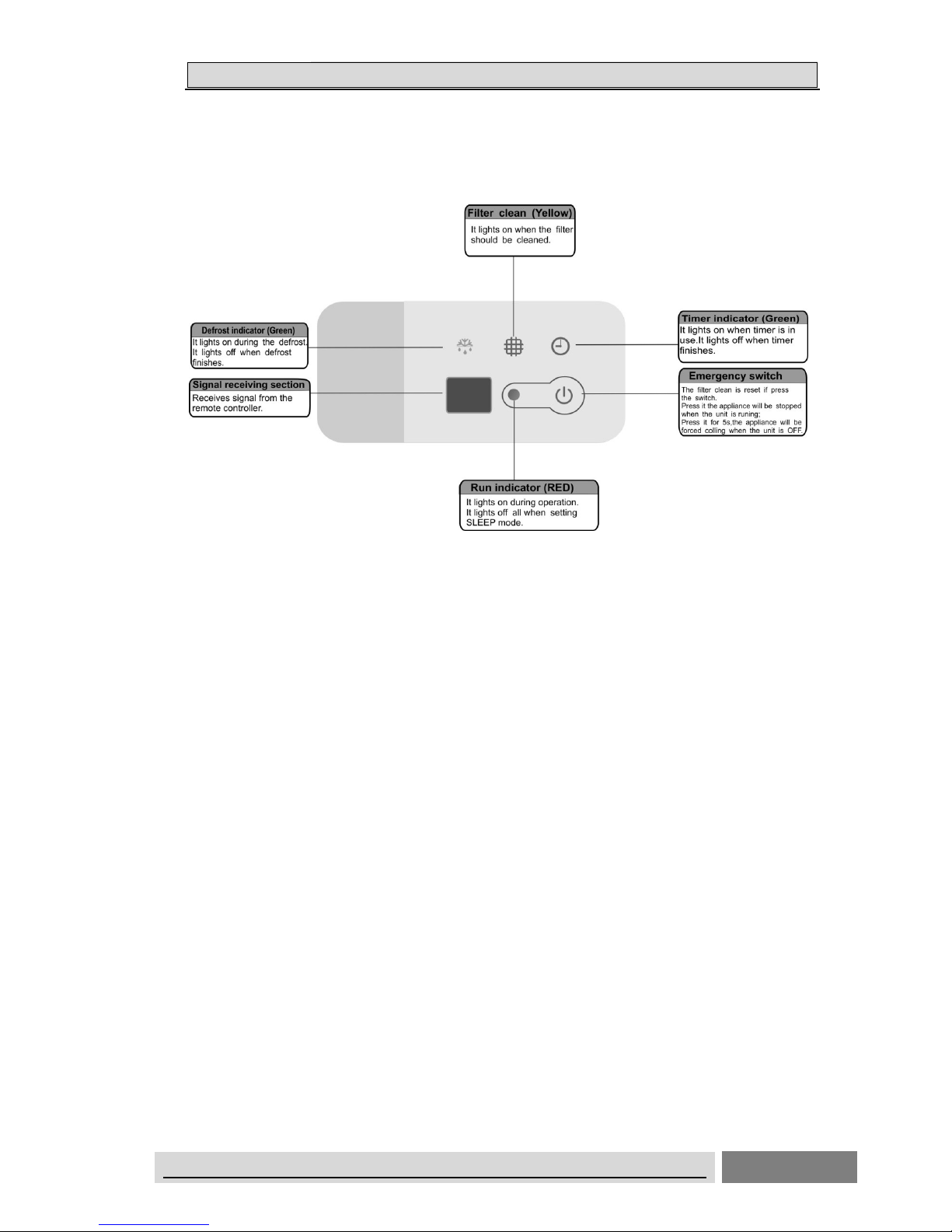
-27 759.6097 822.7471 887.5944 -7.67
7.31
-26 716.2320 775.3041 835.9165 -7.62
7.25
-25 675.5881 730.8775 787.5529 -7.56
7.20
-24 637.4902 689.2583 742.2720 -7.51
7.14
-23 601.7645 650.2533 699.8601 -7.46
7.09
-22 568.2499 613.6835 660.1191 -7.40
7.03
-21 536.7970 579.3832 622.8658 -7.35
6.98
-20 507.2676 547.1989 587.9307 -7.30
6.93
-19 497.5332 516.9882 555.1565 -3.76
6.88
-18 453.4748 488.6192 524.3977 -7.19
6.82
-17 428.9819 461.9693 495.5191 -7.14
6.77
-16 405.9517 436.9251 486.3954 -7.09
10.17
-15 384.2888 413.3808 442.9105 -7.04
6.67
-14 363.9047 391.2386 418.9563 -6.99
6.62
-13 344.7169 370.4072 396.4325 -6.94
6.56
-12 326.6497 350.8019 375.2461 -6.88
6.51
-11 309.6286 332.3441 355.3104 -6.83
6.46
-10 293.5903 314.9620 336.5448 -6.79
6.41
-9 278.4719 298.5822 318.3744 -6.74
6.22
-8 264.2156 283.1464 302.2294 -6.69
6.31
-7 250.7678 268.5936 286.5448 -6.64
6.26
-6 238.0783 254.8686 271.7603 -6.59
6.22
-5 226.1003 241.9200 257.8193 -6.54
6.17
-4 214.7903 229.6997 244.6593 -6.49
6.11
-3 204.1073 218.1630 232.2612 -6.44
6.07
-2 194.0135 207.2681 220.5495 -6.39
6.02
-1 184.4732 196.9759 209.4913 -6.35
5.97
0 175.4533 187.2500 199.0468 -6.30
5.93
1 166.8952 178.0255 189.1529 -6.25
5.88
2 158.8023 169.3067 179.8058 -6.20
5.84
3 151.1467 161.0633 170.9724 -6.16
5.80
4 143.9026 153.2667 162.6216 -6.11
5.75
5 137.0455 145.8905 154.7246 -6.06
5.71
6 130.5528 138.9097 147.2544 -6.02
5.67
7 124.4033 132.3011 140.1856 -5.97
5.62
8 118.5769 126.0429 133.4946 -5.92
5.58
9 113.0550 120.1146 127.1591 -5.88
5.54
Page 78

55.. EELLEECCTTRRIICCAALL DDAATTAA
ON/OFF UNITARY AIR CONDITIONER TECHNICAL& SERVICE MANUAL V6.0
76
T [ ℃ ] Rmin [ KΩ ] Rnom [ KΩ ] Rmax [ KΩ ] DR(MIN)% DR(MAX)%
107.8202 114.4973 121.1586 -5.83
5.50
11 102.8560 109.1728 115.4734 -5.79
5.46
12 98.1470 104.1246 110.0855 -5.74
5.41
13 93.6787 99.3367 104.9778 -5.70
5.37
14 89.4378 94.7946 100.1342 -5.65
5.33
15 85.4114 90.4842 95.5398 -5.61
5.29
16 81.5875 86.3926 91.1805 -5.56
5.25
17 77.9551 82.5076 87.0430 -5.52
5.21
18 74.5034 78.8177 83.1150 -5.47
5.17
19 71.2227 75.3122 79.3848 -5.43
5.13
68.1036 71.9808 75.8414 -5.39
5.09
21 65.1373 68.8141 72.4746 -5.34
5.05
22 62.3155 65.8032 69.2746 -5.30
5.01
23 59.6306 62.9395 66.2324 -5.26
4.97
24 57.0752 60.2152 63.3395 -5.21
4.93
25 54.6424 57.6227 60.5877 -5.17
4.89
26 52.3258 55.1551 57.9695 -5.13
4.85
27 50.1192 52.8058 55.4778 -5.09
4.82
28 48.0168 50.5684 53.1058 -5.05
4.78
29 46.0133 48.4371 50.8472 -5.00
4.74
44.1034 46.4046 48.6960 -4.96
4.71
31 42.2825 44.4711 46.6466 -4.92
4.66
32 40.5458 42.6261 44.6937 -4.88
4.63
33 38.8891 40.8668 42.8323 -4.84
4.59
34 37.3084 39.1890 41.0576 -4.80
4.55
35 35.7998 37.5883 39.3653 -4.76
4.51
36 34.3596 36.0609 37.7511 -4.72
4.48
37 32.9844 34.6030 36.2109 -4.68
4.44
38 31.6710 33.2113 34.7412 -4.64
4.40
39 30.4164 31.8823 33.3383 -4.60
4.37
29.2176 30.6130 31.9988 -4.56
4.33
41 28.0718 29.4004 30.7197 -4.52
4.29
42 26.9765 28.2417 29.4979 -4.48
4.26
43 25.9293 27.1342 28.3306 -4.44
4.22
44 24.9277 26.0755 27.2150 -4.40
4.19
45 23.9697 25.0632 26.1488 -4.36
4.15
46 23.0530 24.0950 25.1293 -4.32
4.12
47 22.1757 23.1688 24.1545 -4.29
4.08
48 21.3360 22.2826 23.2221 -4.25
4.05
49 20.5321 21.4345 22.3301 -4.21
4.01
19.7623 20.6226 21.4766 -4.17
3.98
51 19.0261 19.8468 20.6612 -4.14
3.94
52 18.3211 19.1040 19.8808 -4.10
3.91
Page 79

55.. EELLEECCTTRRIICCAALL DDAATTAA
ON/OFF UNITARY AIR CONDITIONER TECHNICAL& SERVICE MANUAL V6.0
77
T [ ℃ ] Rmin [ KΩ ] Rnom [ KΩ ] Rmax [ KΩ ] DR(MIN)% DR(MAX)%
53 17.6458 18.3926 19.1338 -4.06
3.87
54 16.9986 17.7113 18.4185 -4.02
3.84
55 16.3784 17.0537 17.7335 -3.96
3.83
56 15.7839 16.4332 17.0774 -3.95
3.77
57 15.2139 15.8338 16.4488 -3.92
3.74
58 14.6673 15.2592 15.8464 -3.88
3.71
59 14.1430 14.7083 15.2690 -3.84
3.67
60 13.6400 14.1799 14.7154 -3.81
3.64
61 13.1573 13.6730 14.1846 -3.77
3.61
62 12.6941 13.1868 13.6756 -3.74
3.57
63 12.2494 12.7202 13.1872 -3.70
3.54
64 11.8224 12.2723 12.7186 -3.67
3.51
65 11.4124 11.8424 12.2690 -3.63
3.48
66 11.0185 11.4295 11.8373 -3.60
3.45
67 10.6401 11.0331 11.4230 -3.56
3.41
68 10.2765 10.6522 11.0251 -3.53
3.38
69 9.9271 10.2863 10.6429 -3.49
3.35
70 9.5912 9.9348 10.2756 -3.46
3.32
71 9.2682 9.5968 9.9231 -3.42
3.29
72 8.9576 9.2720 9.5841 -3.39
3.26
73 8.6589 8.9597 9.2583 -3.36
3.23
74 8.3716 8.6594 8.9451 -3.32
3.19
75 8.0951 8.3705 8.6440 -3.29
3.16
76 7.8290 8.0926 8.3544 -3.26
3.13
77 7.5730 7.8252 8.0758 -3.22
3.10
78 7.3264 7.5679 7.8078 -3.19
3.07
79 7.0891 7.3202 7.5499 -3.16
3.04
80 6.8605 7.0818 7.3018 -3.12
3.01
81 6.6403 6.8522 7.0629 -3.09
2.98
82 6.4282 6.6311 6.8329 -3.06
2.95
83 6.2239 6.4182 6.6115 -3.03
2.92
84 6.0269 6.2131 6.3982 -3.00
2.89
85 5.8371 6.0154 6.1928 -2.96
2.86
86 5.6542 5.8249 5.9949 -2.93
2.84
87 5.4777 5.6413 5.8042 -2.90
2.81
88 5.3076 5.4644 5.6205 -2.87
2.78
89 5.1435 5.2937 5.4433 -2.84
2.75
90 4.9853 5.1292 5.2726 -2.81
2.72
91 4.8326 4.9705 5.1079 -2.77
2.69
92 4.6852 4.8174 4.9492 -2.74
2.66
93 4.5430 4.6697 4.7960 -2.71
2.63
94 4.4058 4.5272 4.6483 -2.68
2.61
95 4.2733 4.3896 4.5058 -2.65
2.58
Page 80

55.. EELLEECCTTRRIICCAALL DDAATTAA
ON/OFF UNITARY AIR CONDITIONER TECHNICAL& SERVICE MANUAL V6.0
78
T [ ℃ ] Rmin [ KΩ ] Rnom [ KΩ ] Rmax [ KΩ ]
DR(MIN)% DR(MAX)%
96 4.1453 4.2568 4.3683 -2.62
2.55
97 4.0218 4.1287 4.2355 -2.59
2.52
98 3.9024 4.0049 4.1074 -2.56
2.50
99 3.7872 3.8854 3.9837 -2.53
2.47
100 3.6758 3.7700 3.8643 -2.50
2.44
101 3.5661 3.6585 3.7512 -2.53
2.47
102 3.4601 3.5509 3.6419 -2.56
2.50
103 3.3577 3.4468 3.5362 -2.59
2.53
104 3.2588 3.3463 3.4341 -2.61
2.56
105 3.1632 3.2491 3.3353 -2.64
2.58
106
3.0708 3.1551 3.2398
-2.67
2.61
107
2.9816 3.0643 3.1475
-2.70
2.64
108
2.8953 2.9765 3.0582
-2.73
2.67
109
2.8118 2.8915 2.9717
-2.76
2.70
110
2.7311 2.8093 2.8881
-2.78
2.73
111
2.6531 2.7299 2.8072
-2.81
2.75
112
2.5776 2.6530 2.7289
-2.84
2.78
113
2.5046 2.5785 2.6531
-2.87
2.81
114
2.4340 2.5065 2.5798
-2.89
2.84
115
2.3656 2.4368 2.5087
-2.92
2.87
116
2.2995 2.3693 2.4400
-2.95
2.90
117
2.2354 2.3040 2.3733
-2.98
2.92
118
2.1734 2.2407 2.3088
-3.00
2.95
119
2.1134 2.1795 2.2463
-3.03
2.97
120
2.0553 2.1201 2.1858
-3.06
3.01
121
1.9991 2.0626 2.1271
-3.08
3.03
122
1.9446 2.0070 2.0702
-3.11
3.05
123
1.8918 1.9530 2.0151
-3.13
3.08
124
1.8406 1.9007 1.9617
-3.16
3.11
125
1.7911 1.8500 1.9099
-3.18
3.14
126
1.7430 1.8009 1.8597
-3.22
3.16
127
1.6965 1.7533 1.8110
-3.24
3.19
128
1.6514 1.7071 1.7638
-3.26
3.21
129
1.6076 1.6623 1.7180
-3.29
3.24
130
1.5652 1.6189 1.6736
-3.32
3.27
Page 81

55.. EELLEECCTTRRIICCAALL DDAATTAA
ON/OFF UNITARY AIR CONDITIONER TECHNICAL& SERVICE MANUAL V6.0
79
(R0=15K±2%;
B0/100=3450K±2%)
T [℃] Rmin [ KΩ ] Rnom [ KΩ ] Rmax [ KΩ ] DR(MIN)% DR(MAX)%
-30 60.78 64.77 68.99 -6.16
6.12
-29 57.75 61.36 65.16 -5.88
5.83
-28 54.89 58.15 61.58 -5.61
5.57
-27 52.19 55.14 58.23 -5.35
5.31
-26 49.63 52.30 55.08 -5.11
5.05
-25 47.21 49.62 52.13 -4.86
4.81
-24 44.92 47.10 49.37 -4.63
4.60
-23 42.76 44.73 46.78 -4.40
4.38
-22 40.71 42.49 44.34 -4.19
4.17
-21 38.77 40.38 42.05 -3.99
3.97
-20 36.93 38.39 39.90 -3.80
3.78
-19 35.18 36.51 37.87 -3.64
3.59
-18 33.53 34.74 35.97 -3.48
3.42
-17 31.96 33.06 34.17 -3.33
3.25
-16 30.48 31.47 32.49 -3.15
3.14
-15 29.07 29.97 30.89 -3.00
2.98
-14 27.73 28.56 29.39 -2.91
2.82
-13 26.46 27.22 27.98 -2.79
2.72
-12 25.26 25.95 26.64 -2.66
2.59
-11 24.11 24.75 25.38 -2.59
2.48
-10 23.03 23.61 24.19 -2.46
2.40
-9 21.99 22.53 23.06 -2.40
2.30
-8 21.01 21.51 22.00 -2.32
2.23
-7 20.08 20.54 20.99 -2.24
2.14
-6 19.19 19.62 20.04 -2.19
2.10
-5 18.35 18.74 19.14 -2.08
2.09
-4 17.55 17.92 18.29 -2.06
2.02
-3 16.78 17.13 17.48 -2.04
2.00
-2 16.06 16.38 16.71 -1.95
1.97
-1 15.36 15.67 15.98 -1.98
1.94
0 14.70 15.00 15.29 -2.00
1.90
1 14.08 14.36 14.64 -1.95
1.91
2 13.48 13.75 14.02 -1.96
1.93
3 12.91 13.17 13.43 -1.97
1.94
4 12.36 12.62 12.87 -2.06
1.94
5 11.85 12.09 12.34 -1.99
2.03
6 11.35 11.59 11.83 -2.07
2.03
7 10.88 11.11 11.35 -2.07
2.11
8 10.43 10.66 10.89 -2.16
2.11
9 9.999 10.230 10.450 -2.26
2.11
10 9.590 9.816 10.040 -2.30
2.23
Page 82

55.. EELLEECCTTRRIICCAALL DDAATTAA
ON/OFF UNITARY AIR CONDITIONER TECHNICAL& SERVICE MANUAL V6.0
80
T [℃] Rmin [ KΩ ] Rnom [ KΩ ] Rmax [ KΩ ] DR(MIN)% DR(MAX)%
11 9.199 9.422 9.647 -2.37
2.33
12 8.826 9.047 9.269 -2.44
2.40
13 8.470 8.689 8.910 -2.52
2.48
14 8.129 8.347 8.567 -2.61
2.57
15 7.804 8.021 8.240 -2.71
2.66
16 7.493 7.709 7.928 -2.80
2.76
17 7.196 7.412 7.630 -2.91
2.86
18 6.912 7.127 7.346 -3.02
2.98
19 6.640 6.855 7.074 -3.14
3.10
20 6.381 6.595 6.815 -3.24
3.23
21 6.132 6.347 6.567 -3.39
3.35
22 5.894 6.109 6.330 -3.52
3.49
23 5.667 5.882 6.103 -3.66
3.62
24 5.449 5.664 5.886 -3.80
3.77
25 5.240 5.456 5.678 -3.96
3.91
26 5.048 5.260 5.478 -4.03
3.98
27 4.864 5.072 5.286 -4.10
4.05
28 4.687 4.891 5.101 -4.17
4.12
29 4.517 4.717 4.924 -4.24
4.20
30 4.355 4.550 4.753 -4.29
4.27
31 4.198 4.390 4.589 -4.37
4.34
32 4.048 4.236 4.431 -4.44
4.40
33 3.904 4.089 4.280 -4.52
4.46
34 3.766 3.946 4.134 -4.56
4.55
35 3.663 3.810 3.994 -3.86
4.61
36 3.506 3.679 3.859 -4.70
4.66
37 3.383 3.552 3.729 -4.76
4.75
38 3.265 3.431 3.604 -4.84
4.80
39 3.152 3.314 3.484 -4.89
4.88
40 3.043 3.202 3.368 -4.97
4.93
41 2.938 3.094 3.257 -5.04
5.00
42 2.838 2.990 3.149 -5.08
5.05
43 2.741 2.890 3.046 -5.16
5.12
44 2.648 2.793 2.946 -5.19
5.19
45 2.558 2.701 2.850 -5.29
5.23
46 2.472 2.611 2.758 -5.32
5.33
47 2.389 2.525 2.669 -5.39
5.40
48 2.309 2.443 2.583 -5.49
5.42
49 2.232 2.363 2.500 -5.54
5.48
50 2.158 2.286 2.421 -5.60
5.58
51 2.087 2.212 2.344 -5.65
5.63
52 2.018 2.140 2.269 -5.70
5.69
53 1.952 2.072 2.198 -5.79
5.73
Page 83

55.. EELLEECCTTRRIICCAALL DDAATTAA
ON/OFF UNITARY AIR CONDITIONER TECHNICAL& SERVICE MANUAL V6.0
81
T [℃] Rmin [ KΩ ] Rnom [ KΩ ] Rmax [ KΩ ] DR(MIN)% DR(MAX)%
54 1.888 2.005 2.129 -5.84
5.82
55 1.827 1.941 2.062 -5.87
5.87
56 1.767 1.880 1.998 -6.01
5.91
57 1.710 1.820 1.936 -6.04
5.99
58 1.655 1.763 1.876 -6.13
6.02
59 1.602 1.707 1.818 -6.15
6.11
60 1.551 1.654 1.762 -6.23
6.13
61 1.502 1.602 1.709 -6.24
6.26
62 1.452 1.553 1.657 -6.50
6.28
63 1.409 1.505 1.606 -6.38
6.29
64 1.364 1.458 1.558 -6.45
6.42
65 1.322 1.413 1.511 -6.44
6.49
66 1.280 1.370 1.466 -6.57
6.55
67 1.241 1.328 1.422 -6.55
6.61
68 1.202 1.288 1.379 -6.68
6.60
69 1.165 1.249 1.339 -6.73
6.72
70 1.129 1.211 1.299 -6.77
6.77
71 1.095 1.175 1.261 -6.81
6.82
72 1.061 1.140 1.224 -6.93
6.86
73 1.029 1.106 1.188 -6.96
6.90
74 0.9977 1.073 1.153 -7.02
6.94
75 0.9676 1.041 1.120 -7.05
7.05
76 0.9385 1.011 1.088 -7.17
7.08
77 0.9104 0.9810 1.056 -7.20
7.10
78 0.8833 0.9523 1.026 -7.25
7.18
79 0.8570 0.9246 0.9971 -7.31
7.27
80 0.8316 0.8977 0.9687 -7.36
7.33
81 0.8071 0.8717 0.9412 -7.41
7.38
82 0.7834 0.8466 0.9146 -7.47
7.43
83 0.7604 0.8223 0.8888 -7.53
7.48
84 0.7382 0.7987 0.8639 -7.57
7.55
85 0.7167 0.7759 0.8397 -7.63
7.60
86 0.6958 0.7537 0.8161 -7.68
7.65
87 0.6755 0.7322 0.7933 -7.74
7.70
88 0.6560 0.7114 0.7712 -7.79
7.75
89 0.6371 0.6913 0.7498 -7.84
7.80
90 0.6188 0.6718 0.7291 -7.89
7.86
91 0.6011 0.6530 0.7051 -7.95
7.39
92 0.5840 0.6348 0.6897 -8.00
7.96
93 0.5674 0.6171 0.6709 -8.05
8.02
94 0.5514 0.6000 0.6527 -8.10
8.07
95 0.5359 0.5835 0.6350 -8.16
8.11
96 0.5209 0.5675 0.6179 -8.21
8.16
Page 84

55.. EELLEECCTTRRIICCAALL DDAATTAA
ON/OFF UNITARY AIR CONDITIONER TECHNICAL& SERVICE MANUAL V6.0
82
T [℃] Rmin [ KΩ ] Rnom [ KΩ ] Rmax [ KΩ ] DR(MIN)% DR(MAX)%
97 0.5064 0.5519 0.6014 -8.24
8.23
98 0.4923 0.5369 0.5853 -8.31
8.27
99 0.4787 0.5224 0.5698 -8.37
8.32
100 0.4655 0.5083 0.5547 -8.42
8.36
101 0.4528 0.4946 0.5401 -8.45
8.42
102 0.4404 0.4814 0.5259 -8.52
8.46
103 0.4284 0.4685 0.5121 -8.56
8.51
104 0.4168 0.4561 0.4988 -8.62
8.56
105 0.4056 0.4440 0.4859 -8.65
8.62
106
0.3947 0.4323 0.4733 -8.70 8.66
107
0.3841 0.4210 0.4611 -8.76 8.70
108
0.3739 0.4100 0.4493 -8.80 8.75
109
0.3640 0.3993 0.4379 -8.84 8.81
110
0.3544 0.3890 0.4267 -8.89 8.84
111
0.3450 0.3789 0.4159 -8.95 8.90
112
0.3360 0.3692 0.4055 -8.99 8.95
113
0.3272 0.3597 0.3953 -9.04 9.01
114
0.3187 0.3505 0.3854 -9.07 9.06
115
0.3104 0.3416 0.3758 -9.13 9.10
116
0.3024 0.3330 0.3665 -9.19 9.14
117
0.2947 0.3246 0.3574 -9.21 9.18
118
0.2871 0.3164 0.3468 -9.26 8.77
119
0.2798 0.3085 0.3401 -9.30 9.29
120
0.2727 0.3008 0.33 -9.34 9.34
Page 85

66.. CCOONNTTRROOLL MMOODDE
E
ON/OFF UNITARY AIR CONDITIONER TECHNICAL& SERVICE MANUAL V6.0
83
6-1 Indoor control mode
1.Major general technical parameters
1 Remote receiver distance: 8 m.
2 Remote receiver angle: Less than 80 degrees.
3 Temperature control accuracy: ±1℃.
4 Time error: Less than 1%.
2. Functions of the controller
Control function
2.1 Emergency switch
Press the emergency button can realize the starting or closing Machine, starting up
according to the automatic mode of operation(invalid for duct type air-conditioner)
① Press this button to turn ON the unit, the conditioner will be run in auto mode, and
press it again to turn off.
② When the machine is turned OFF, by press and hold the emergency switch for 5 seconds,
with 3 beeps , the indoor unit would turn to emergency run. In such station, machine would
be forced to turn to cooling operation with the indoor fan speed being set at high speed, the
flaps sweeping and the air conditioner’s operation is irrelevant with room temperatures.
③ If a remote signal has been received during the emergency run, the machine will operate
upon the command of such a remote signal.
2.2 Operator-machine communication
Air conditioning and remote controller is provided with a temperature sensor. The
remote controller on the temperature sensor to detect the default settings of room
temperature at room temperature. If the indoor control unit for long time have not received
remote control signal, will automatically switch to the air conditioner body temperature
sensor.
2.3 Timer function
1. Timer on: When set to start in a time by the remote controller, the air conditioner starts
in the timer on condition. When the set time is up, the air conditioner will turn on and
operates in the preset conditions after receiving a signal from the remote controller. If the air
conditioner has not received a signal from the remote controller when the set time is up, it
will automatically start and operate in the preset conditions.
2. Timer off: When set to stop in a set time by the remote controller, the air conditioner
Page 86

66.. CCOONNTTRROOLL MMOODDE
E
ON/OFF UNITARY AIR CONDITIONER TECHNICAL& SERVICE MANUAL V6.0
84
will start in the timer off condition. When the set time is up, the air conditioner will turn off
after receiving a signal from the remote controller. If the air conditioner has not received a
signal from the remote controller when the set time is up, it will turn off automatically.
3. Neither the turning on nor turning off operation will cancel the timer function。
2.4 Sleep
1. In the heating, cooling or dehumidifying mode, press the “Sleep” button on the remote
controller to start or cancel the sleep function in turn, and at the same time the sleep icon on
the display screen will be on or off accordingly.
2. In the heating mode, the set temperature will decrease automatically after the sleep
function is started.
3. In the cooling mode, the set temperature will rise automatically after the sleep function
is started.
4. In default, the setting is to cancel the sleep function. Turning off the unit will also
cancel the sleep function.
2.5 High efficient run function
In Cool, Dehumidification, Fan mode, press the "HIGH POWER " to enter the
refrigeration mode, set the temperature automatically adjust to 18℃; the Fan speed is
powerful speed; frequency of high frequency operation.
In the heating mode, powerful function is invalid for H1 wireless remote controller.
2.6 mute function (only for H1 wireless remote controller)
In the indoor machine operation mode,You may turn on mute function and turn off mute
function by mute key, The air conditioner will run by mute fan speed in mute mode
2.7 prevent cooling wind mode
In the heating-run, to prevent the indoor fan from blowing cold air, the indoor fan will stop
or run slowly until the coil is warmth.
2.8 blow waste heating and waste cooling function
The heating mode, remote shutdown, such as indoor heat exchanger temperature is
Page 87

66.. CCOONNTTRROOLL MMOODDE
E
ON/OFF UNITARY AIR CONDITIONER TECHNICAL& SERVICE MANUAL V6.0
85
higher, the wind blowing out opportunities continue to run the waste heat.
Cool and dehumidification mode , after the compressor close, indoor machine will
continue to set the speed of operation for a period of time.
2.9 automatically model
This model does not automatically model function, emergency button cannot set the
automatic mode of operation, can use the emergency switch shutdown, remote setting the
automatic mode of indoor machine with remote signal. (emergency button only for cassette
type)
2.10 Dehumidifying method:
Remote control setting dehumidifying mode, indoor machine forced to run at low
speed(high power key or a strong bond also maintain a low wind speed), the outdoor
machine according to the refrigeration mode operation.
2.11 Self Recovery of Power Break
When the power supply is recovered after break, all preset are still effective and the
air-conditioner can run according to the original setting.
How to set/cancel
It can be set by wire remote controller YXE-C01U/YXE-C02U.
Details see Internal control parameter adjustment.
2.12 FAULT CODE
The fault code can be showed by LED on the indoor panel.
2.13 Filter clean
Filer clean led will light up when air filter is clogged with dust.
How to reset:
①Press Emergency switch;
②Press high power button for 5s;
③By wire remote controller YXE-C01U/YXE-C02U, press cancel button for 3s.
6-2 Outdoor mode control
Control function
Page 88

66.. CCOONNTTRROOLL MMOODDE
E
ON/OFF UNITARY AIR CONDITIONER TECHNICAL& SERVICE MANUAL V6.0
86
1.Cooling Anti-freeze Protection
To prevent indoor air conditioner evaporator temperature is too low, the indoor coil
sensor for real time detection of evaporator. If the indoor coil temperature is too low, the
compressor will protect.
2. Overload Protection
Air can heat exchanger temperature sensor for monitoring, when the sensor when
the temperature is too high, the compressor will be automatic protection
3. Exhaust temperature protection
To prevent deterioration due to high exhaust temperature of compressor, the
machine will realize the real-time detection of the temperature of exhaust gas. If the
temperature is too high compressor automatic protection
4.Operation Mode
Air conditioning mode is the operation mode set by users through remote controller,
four modes are available: cooling, heating, dehumidification, as well as fan mode.
5. Four-way Valve Control
Four-way valve of the outdoor machine shuts down when cooling and defrosting
but starts when heating. During the heating process, the four way valve to stop working for a
period of time after compressor disconnect.
6. Start-up Protection:
To prevent compressor from restart frequently in the condition that system
pressure has not been completely balanced, it can’t be restarted within 3 minutes.
7. Pressure Protection:
Page 89

66.. CCOONNTTRROOLL MMOODDE
E
ON/OFF UNITARY AIR CONDITIONER TECHNICAL& SERVICE MANUAL V6.0
87
When the pressure increases to a preset value, the pressure switch will
automatically protect. Compressor will stop and report the fault code protection.
Page 90

77.. TTRROOUUBBLLEE SSHHOOOOTTIINNGG
ON/OFF UNITARY AIR CONDITIONER TECHNICAL& SERVICE MANUAL V6.0
88
Trouble guide
When the air conditioner failure occurs, the fault code will displays on control board , wire remote controller
or display panel.
HOW TO CHECK FAULT CODES
INDOOR UNIT
1.WALL MOUNTED TYPE
For Free-match series
Run the air-conditioner by wireless remote controller , continue pressing “SLEEP ”button for 4 times, fault
codes will flashing rapidly on the LCD . If no fault , display "00".
“ER”shows indoor display panel communication fault with indoor unit control board .
For VRF series
Fault codes flash rapidly on the LCD.
2.FLOOR STANDING TYPE
L5B (indoor box code)series
In the case of no button-locked,continue pressing “CLOCK”button for 8 times ,fault codes will display on
the LCD for 10 seconds,automatically disappears after 10seconds.
Continue pressing “SLEEP”button of wireless remote controller for 8 times ,fault codes will display on the
LCD for 10 seconds,automatically disappears after 10seconds.
“ER”shows indoor display panel Communication fault with indoor unit control board
L5C(indoor box code) series
Continue pressing “SLEEP”button of wireless remote controller for4 times ,fault codes will display on the
LCD for 10 seconds,automatically disappears after 10seconds.
3.DUCT , CASSETTE,CEILING&FLOOR TYPE
(1) ERROR CODES INDICATED BY WIRE REMOTE CONTROLLER(see fig. below)
MOEDL:YXC-A01U(E)
When failure occurs, this lamp light ON.
This number shows ERROR CODE.
When display“FE” ,shows that the wire
controller can’t receive the signals of
indoor unit control board ,please check
Page 91

77.. TTRROOUUBBLLEE SSHHOOOOTTIINNGG
ON/OFF UNITARY AIR CONDITIONER TECHNICAL& SERVICE MANUAL V6.0
89
MOEDL:YXE-C01U
FIG.2 ERROR CODE DISPLAY ON WIRE REMOT CONTROLLER
(2)CHECK ERROR CODES BY DISPLAY PANEL(CASSETTE type and CEILING &FLOOR type)
Display by lamp indicator
Lamp RUN(LED2 ,red) and Lamp DEFROST(LED5 ,green)flashing,Lamp RUN display fault code ten
digit number,lamp DEFROST display fault code single digit number (as shown fig. below).
For example,fault code 36: led RUN & defrost flash 3 times at the same time, and led DEFROST
continue flash 3 times, reports No. 36 fault.
Page 92

77.. TTRROOUUBBLLEE SSHHOOOOTTIINNGG
ON/OFF UNITARY AIR CONDITIONER TECHNICAL& SERVICE MANUAL V6.0
90
Page 93

77.. TTRROOUUBBLLEE SSHHOOOOTTIINNGG
ON/OFF UNITARY AIR CONDITIONER TECHNICAL& SERVICE MANUAL V6.0
91
LED FALSH CONTROL:flash 300mS(T1),off 300mS(T2),after 2000mS(T3)fault code repeat
displays. (as shown below)
3
4
T1 T2 T3
Fig.2 LED FALSH CONTROL
3.Duct type indoor units of VRF---FAULT CODE DISPLAY BY INDOOR BOARD
LED2 and LED5 are failure indicate
lamps,
LED2(RED) indicate fault code ten
digit number, LED5(GREEN) indicate
single digit number code
Page 94

77.. TTRROOUUBBLLEE SSHHOOOOTTIINNGG
ON/OFF UNITARY AIR CONDITIONER TECHNICAL& SERVICE MANUAL V6.0
92
2.OUTDOOR UNIT FAULT CODE DISPLAY
(1) ON/OFF UNITARY TYPE(with outdoor control box)
Fault code display by indicate lamps of outdoor control board flash.
The times that the lamp flashes equal to fault code.
LED FALSH CONTROL:flash 300mS(T1),off 300mS(T2),after 900mS(T3)fault code repeat displays.
(as shown below)
3
4
T1 T2 T3
(2)INVERTER UNITARY AIR CONDITONER , MULTI-SPLIT TYPE AIR CONDITONER&VRF:
Fault code will display on digital tube board.
LED2-fault code lamp
Page 95

77.. TTRROOUUBBLLEE SSHHOOOOTTIINNGG
ON/OFF UNITARY AIR CONDITIONER TECHNICAL& SERVICE MANUAL V6.0
93
FOR INVERTER UNITARY AIR CONDITONER&VRF
* VRF:
Indoor unit can indicate both indoor failure and outdoor failure ,but outdoor only indicate outdoor’s.
FOR MULTI-SPLIT TYPE
Error code display on digital tube board directly.
Digital Tube
Outdoor Control Board
Page 96

77.. TTRROOUUBBLLEE SSHHOOOOTTIINNGG
ON/OFF UNITARY AIR CONDITIONER TECHNICAL& SERVICE MANUAL V6.0
94
3.Fault code display ( Driver Board )
The lamp of driver board flash shows failure occur.
Or, fault code can be check on digital tube board .
Page 97

77.. TTRROOUUBBLLEE SSHHOOOOTTIINNGG
ON/OFF UNITARY AIR CONDITIONER TECHNICAL& SERVICE MANUAL V6.0
95
The following is the fault code table of outdoor.
sheet 1 Outdoor Error Code
Faul
t
cod
e
Fault Description Possible Reason of Abnormality How to Deal With REMARKS
1
Outdoor ambient temperature
sensor fault
1.The outdoor ambient temperature sensor
connect loose;
2.The outdoor ambient temperature sensor is
failure;
3.The sampling circuit is failure
1.Reconnect the outdoor ambient
temperature sensor;
2.Replace the outdoor ambient
temperature sensor components;
3.Replace the outdoor control board
components.
2
Outdoor coil temperature
sensor fault
1.The outdoor ambient temperature sensor
connect loose;
2.The outdoor ambient temperature sensor is
failure; 3.The sampling circuit is failure
1.Reconnect the outdoor ambient
temperature sensor;
2.Replace the outdoor ambient
temperature sensor components;
3.Replace the outdoor control board
components.
3
The unit over-current turn off
fault
1.Control board current sampling circuit is
failure; 2.The current is over high because of
the supply voltage is too low
3.The compressor is blocked
4. Overload in cooling mode
5.Overload in heating mode
1. Replace the electrical control board
components;
2. Normally protection
3. Replace the compressor
4. Please see the Note 3 5. Please see
the Note 4
4
EEprom Data error
1.EE components is failure; 2.EE
components control circuit failure;
3.EE components insert incorrect
1.Replace the EE components;
2.Replace the outdoor control board
components; 3.Reassembly the EE
components.
5
Cooling freezing protection(the
indoor coil temperature is too
low) or heating overload(indoor
coil temperature is too high)
1.The indoor unit can not blow air normally;
2.The room temperature is too low in cooling
mode or the room temperature is too high in
heating;
3.The filter is dirty;
4.The duct resistance of the duct
5.The setting fan speed is too low
6. The indoor unit has been
installed without standard
1.Check the indoor fan, indoor fan
motor and evaporator whether
normally;
2. Normally protection
3.Clean the filter;
4.Check the volume control valve,
duct length etc;
5.Set the speed with high speed;
6.Reinstall the indoor unit refer to the
user manual to change the distance
between the indoor unit and the wall
or ceiling.
Page 98

77.. TTRROOUUBBLLEE SSHHOOOOTTIINNGG
ON/OFF UNITARY AIR CONDITIONER TECHNICAL& SERVICE MANUAL V6.0
96
Faul
t
cod
e
Fault Description Possible Reason of Abnormality How to Deal With REMARKS
6
Motor blockage protection
1.Outdoor ambient temperature sensor fault;
2. Outdoor coil temperature sensor fault;
3.Outdoor control board fault.
1.Replace outdoor ambient
temperature sensor;
2.Replace outdoor coil temperature
sensor;
3.Replace Outdoor control board.
Applied to
ON/OFF
air-condition
ers with 2
control
boards
7
The communication fault
between the indoor unit and
outdoor unit
1.The connection cable connect wrong
between the indoor unit and outdoor unit;
2.The communication cable connect loose;
3.The communication cable is fault;
4.The indoor control board is fault;
5.The outdoor control board is
fault;
6.Communication circuit fuse open;
7.The specification of communication cable is
incorrect.
1.Reconnect the connection cable refer
to the wiring diagram;
2.Reconnect the communication cable;
3.Replace the communication cable;
4.Replace the indoor control board;
5.Replace the outdoor control board;
6.Check the communication circuit,
adjust the DIP switch and the
short-circuit fuse.
7.Choose suitable communication
cable refer to the user manual
8 Phase current imbalance
1.The supply voltage fluctuates more than
4%;
2.The compressor power cord connect loose;
3.The AC contactor is fault;
4.The compressor motor fault.
1.Normally protection;
2.Reconnect the wire refer to thewiring
diagram;
3.Replace the AC contactor;
4.Replace the compressor.
Application
of
three-phase
power
supply
models
9 U phase current fault
1.Compressor U phase power cord is fault or
connect wrong;
2.Outdoor control board is fault;
3.The Compressor is fault
1.Replace the U phase power cord or
reconnect the U phase power cord
refer to the wiring diagram;
2.Replace the outdoor control board;
3.Replace the compressor.
Application
of
three-phase
power
supply
models
10 V phase current fault
1.Compressor V phase power cord is fault or
connect wrong;
2.The outdoor control board is fault;
3.The compressor is fault
1.Replace the V phase power cord or
reconnect the V phase power cord refer
to the wiring diagram;
2.Replace the outdoor control board;
3.Replace the compressor.
Application
of
three-phase
power
supply
models
Page 99

77.. TTRROOUUBBLLEE SSHHOOOOTTIINNGG
ON/OFF UNITARY AIR CONDITIONER TECHNICAL& SERVICE MANUAL V6.0
97
Faul
t
cod
e
Fault Description Possible Reason of Abnormality How to Deal With REMARKS
11 phase wrong failure
1.Three-phase power is abnormal;
2.The outdoor wiring connect wrong;
3. The outdoor control board is failure
1.Normally protection, please check
the supply power
2.Check the wiring connection refer to
the wiring diagram;
3.Replace the outdoor control board
Application
of
three-phase
power
supply
models
12 voltage absent phase
1.Three-phase power is abnormal;
2.The outdoor wiring connect wrong;
3.The outdoor control board is failure.
1. Normally protection
2. Check the wiring connection refer to
the wiring diagram;
3. Replace the outdoor control board
Application
of
three-phase
power
supply
models
13
Compressor overheat
protector device
1. The wiring of the overload protector
connect loose.
2. The overload protector is failure .
3. The refrigerant is not enough;
4. The installation pipe is too long than
normal, but not add the enough refrigerant;
5. The expansion valve is failure;
6. The outdoor control board is failure
1. Reconnect the wiring of the overload
protector;
2. Replace the overload protector;
3. Check the welding point of the unit to
confirm whether it is leakage, and then
recharge the refrigerant;
4. Add the refrigerant;
5. Replace expansion valve;
6. Replace the outdoor control board.
14
the high pressure switch
operate or the unit turn off for
high pressure
protection
1.The wiring of the high pressure protector
connect loose;
2.The high pressure protector is failure;
3.The outdoor control board is abnormal;
4. Overload in cooling;
5. Overload in heating.
1.Reconnect the wiring the high
pressure protector;
2. Replace the high pressure protector;
3. Replace the outdoor control board;
4. Please refer to the Note 3;
5. Please refer to the Note 4.
Applied to
models with
high
pressure
switch or
pressure
sensor
15
the low pressure switch
protection or
the unit turn off for low
pressure
protection
1. The low pressure switch is failure;
2.The wiring of the low pressure switch
connect loose;
3.The refrigerant is not enough;
4.The expansion valve failure in heating
mode;
5.The outdoor control board is abnormal.
1. Reconnect the wiring of the low
pressure switch;
2. Replace the low pressure switch;
3.Check the welding point to confirm
whether the unit is leakage, and then
add some refrigerant;
4. Replace the expansion valve;
5. Replace the outdoor control board.
Applied to
models with
low pressure
switch or
pressure
sensor
16
overload protection in cooling
mode
System overload Please refer to the Note 3.
17
Discharge temperature sensor
fault
1.The wiring of the discharge temperature
sensor connect loose;
2.The discharge temperature sensor is
1.Reconnect the wiring of thedischarge
temperature sensor;
2.Replace the discharge temperature
Page 100

77.. TTRROOUUBBLLEE SSHHOOOOTTIINNGG
ON/OFF UNITARY AIR CONDITIONER TECHNICAL& SERVICE MANUAL V6.0
98
Faul
t
cod
e
Fault Description Possible Reason of Abnormality How to Deal With REMARKS
failure;
3.The sampling circuit is abnormal.
sensor;
3.Replace the outdoor control board.
18 AC voltage is abnormal
1.The AC voltage>275V or <160V.
2.The AC voltage of sampling circuit on the
driver board is abnormally
1. Normally protection, please check
the supply power;
2. Replace the driver board.
MUTI-SPLIT
TYPE ONLY
19
Suction temperature sensor
fault
1.The wiring of the suction temperature
sensor connect loose;
2. The suction temperature sensor is failure;
3. The sampling circuit is abnormally
1.Reconnect the wiring of the suction
temperature sensor;
2.Replace the suction temperature
sensor;
3.Replace the outdoor control board.
20
The temperature sensor for the
inlet tube of the condenser fault
1.The wiring of the temperature sensor for the
inlet tube connect loose;
2.The temperature sensor for the inlet tube is
failure;
3.The sampling circuit is abnormally
1.Reconnect the wiring of the
temperature sensor for the inlet tube of
the condenser;
2.Replace the temperature sensor for
the inlet tube of the condenser;
3.Replace the outdoor control board.
21
The outlet tube of the
condenser temperature sensor
fault
1.The wiring of the temperature sensor for the
outlet tube connect loose;
2.The temperature sensor for the outlet tube
is failure;
3.The sampling circuit is abnormally
1. Reconnect the wiring of the
temperature sensor for the outlet tube
of the condenser.
2.Replace the temperature sensor for
the outlet tube of the condenser;
3.Replace the outdoor control board.
22 The defrosting sensor fault
1.The wiring of the defrosting sensor connect
loose;
2.The defrosting sensor is failure;
3.The sampling circuit is abnormally
1. Reconnect the wiring of the
defrosting sensor;
2. Replace the defrosting sensor;
3. Replace the outdoor control board.
23
Expansion valve A tube(thin)
sensor fault
1. The wiring of the sensor for the expansion
valve A(thin tube) connect loose;
2.The sensor for the expansion A(thin tube) is
failure;
3. The sampling circuit is abnormally
1. Reconnect the wiring of the sensor
for the expansion valve A(thin tube);
2. Replace the sensor for the
expansion valve A(thin tube);
3. Replace the outdoor control board.
FOR
MUTI-SPLIT
&Inverter
unitary types
24
Expansion valve B (thin)tube
sensor fault
1. The wiring of the sensor for the expansion
valve B ( thin tube )connect loose;
2.The sensor for the expansion valve B(thin
tube) is failure;
3.The sampling circuit is abnormally
1.Reconnect the wiring of the sensor
for the expansion valve B(thin tube);
2.Replace the sensor for the expansion
valve B(thin tube);
3. Replace the outdoor control board.
FOR
MUTI-SPLIT
outdoor
25
Expansion valve C (thin)tube
sensor fault
1. The wiring of the sensor for the expansion
valve C(thin tube) connect loose;
2.The sensor of the expansion valve C(thin
tube)is failure;
3.The sampling circuit is abnormally
1. Reconnect the wiring of the sensor
for the expansion valve C(thin tube);
2. Replace the sensor for the
expansion valve C(thin tube);
3. Replace the outdoor control board.
FOR
MUTI-SPLIT
outdoor
 Loading...