

Hisense AUD-24UX4SZLH, AUD-36UX4SAMH, AUC-24UX4SZEA, AUC-18UX4SGAA, AUD-60UX6SPHH Service Manual
...Page 1

DC INVERTER AIR CONDITIONER
SERVICE MANUAL
V:2.2(test edition)
UNIT:
Hisense Corporation
AUD-18UX4SGKL
AUC-18UX4SGAA
AUD-24UX4SZLH
AUC-24UX4SZEA
AUD-36UX4SAMH
AUC-36UX4SAEA
AUD-48UX6SPHH
AUC-48UX6SPFA
AUD-60UX6SPHH
AUC-60UX6SPFA
AUD-18UX4SZKL1
AUC-18UR4SZAA1
AUD-24UX4SALH1
AUC-24UR4SAE A1
AUD-36UX4SAMH1
AUC-36UR4SAE A1
Page 2

Table of contents
Page
1.OPERATING RANGE 1
2.SPECIFICATION 2
2-1 Unit specifications 2
2-2 Major component specifications 14
2-3 Other component specifications 16
3.OUTLINES AND DIMENSIONS 18
3-1 INDOOR 18
3-2 OUTDOOR 23
4.REFRIGERANT FLOW DIAGRAM 27
4-1 Refrigerant flow diagram 27
4-2 Evacuation procedures 29
4-3 Evacuation direction 30
5.ELECTRICAL DATA 31
5-1 Electric wiring diagrams 31
5-2 Electric control 41
5-3 Sensor parameter 51
6.CONTROL MODE 59
6-1 Indoor control mode 59
6-2 Outdoor control mode 62
7.TROUBLESHOOTING 65
7-1 Error codes 65
8.CHECKING COMPONENTS 68
8-1 Check refrigerant system 68
8-2 Check parts unit 70
9.PARTS LIST 79
9-1 Indoor 58
9-2 Outdoor 72
Page 3

11.. OOPPEERRAATTIINNGG RRAANNGGE
E
1
Note:
For AUC-18UR4SZAA1 、 AUC-24UR4SAEA1 、 AUC-36UR4SAEA1 、 AUD-18UX4SZKL1 、
AUD-24UX4SALH1、AUD-36UX4SAMH1
Temperature Temp
COOLING
Maximum 43 ℃
Minimum 15 ℃
HEATING
Maximum 24℃
Minimum -10℃
Temperature Temp
COOLING
Maximum 48 ℃
Minimum 15 ℃
HEATING
Maximum 24℃
Minimum -10℃
Page 4
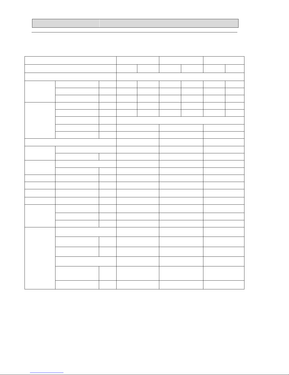
22.. SSPPEECCIIFFIICCAATTIIOONNSS
2
2-1. Unit specifications
2-1-1.OUTDOOR UNIT
Model
AUW-18U4SG
AUW-24U4SZ
AUW-36U4SA
Function Cooling Heating Cooling Heating Cooling Heating
Power supply a.c 220V~240V/50Hz
Capacity
Capacity kW
Dehumidification l /h ---- ---- ---- ---- ---- ----
Air flow m3/h ---- ---- ---- ---- ---- ----
Electrical data
Rated current A 6.58 6.57 8.1 8.1
12.4
12.8
Rated input kW 1.482 1.48 1.83 1.84
2.85
2.93
Auxiliary heater A ------
Power factor %
99.9% 99.9% 99.9%
Max. current A 9.53 12.5
20.0
EER/COP -- -- --
Compressor
Model DA130S1C-20FZ
ATL165SD-C9AU DA250S2C-30MT
Winding resistance
Ω
0.95(20
℃
) 0.590
(at75℃)
0.95(20℃)
Outdoor
fan motor
Model YDK29-6I-22 YDK70-6H-3 YDK95-6-9043
Winding resistance (at20℃)
Ω M:283.5;A:180 M:78;A:80 M:59.1;A:85.8
Net size L×W×H cm 80×26×57 98*35*64
95×34×84
Package size L×W×H cm 94×36×64 108*42*72
111× 46×9 8
Net weight kg 35.5 50 70
Gross weight kg 39 56 74
Refrigerant
piping
Liquid pipe mm 6.35 9.52 9.52
Gas pipe mm 12.7 15.88 15.88
Connection method Flare Flare
Special
remarks
Air direction ---- ---- ----
Sound level (Hi) dB 56 58 58
Fan speed (Hi) rpm 900 840 800
Fan speed regulator 3 3 3
Refrigerant filling
capacity(R410a)
kg 1.27 1.5 2.1
Throttle mode EEV EEV EEV
Page 5
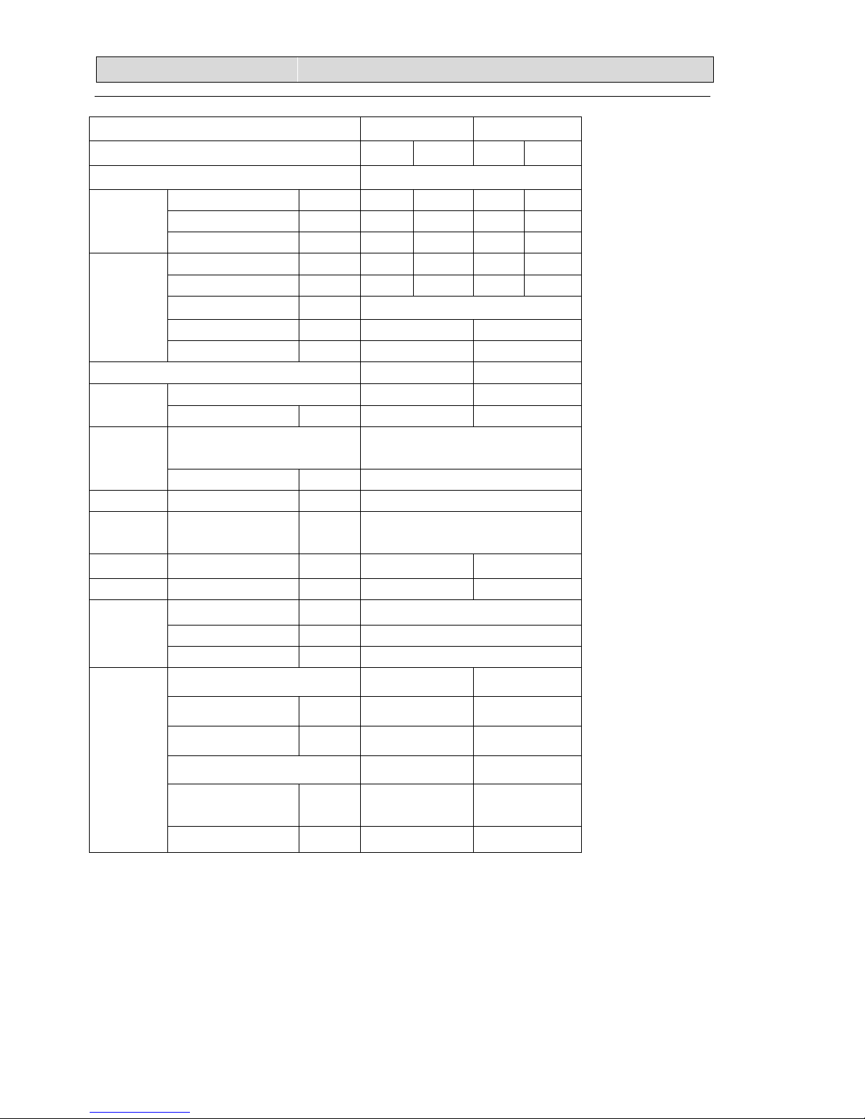
22.. SSPPEECCIIFFIICCAATTIIOONNSS
3
NOTE :Test conditions:
Cooling : Indoor: DB27℃/ WB19℃ Outdoor: DB35℃/ WB24℃
Heating: Indoor: DB20℃/ WB15℃ Outdoor: DB7℃/ WB 6℃
Model
AUW-48U6SP
AUW-60U6SP
Function Cooling Heating Cooling Heating
Power supply a.c 380V~418V/50Hz
Capacity
Capacity kW
Dehumidification l /h ---- ---- ---- ----
Air flow m3/h ---- ---- ---- ----
Electrical dat
a
Rated current A 5.5 6.0 8.8 9.3
Rated input kW 3.52 3.75 4.895 5.25
Auxiliary heater A ------
Power factor %
99.9% 99.9%
Max. current A 10.3 15.0
EER/COP -- --
Compressor
Model TNB306FPNMC LNB42FSAMC
Winding resistance
Ω
1.02
(at20℃)
0.53
(at20℃)
Outdoor
fan motor
Model
YDK65-6-9024
YDK65-6-9061
Winding resistance (at20℃)
Ω M:83;A:100.9
Net size L×W×H cm
95×34×138
Package
size
L×W×H cm
111× 46×1 53
Net weight kg 101 108
Gross weigh
t
kg 107 112
Refrigerant
piping
Liquid pipe mm 9.52
Gas pipe mm 19.05
Connection method Flare
Special
remarks
Air direction ---- ----
Sound level (Hi) dB 60 60
Fan speed (Hi) rpm 700 700
Fan speed regulator 3 3
Refrigerant filling
capacity(R410a)
kg 3.0 3.5
Throttle mode EEV EEV
Page 6

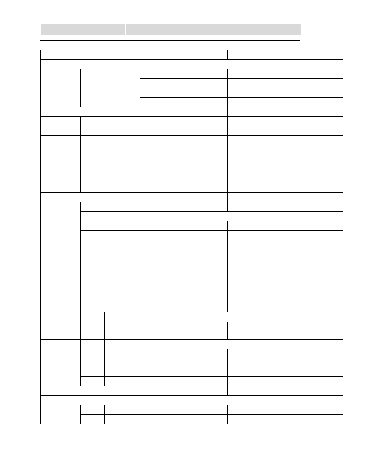
22.. SSPPEECCIIFFIICCAATTIIOONNSS
4
2-1-2.INDOOR UNIT
Model AUD-18UX4SKL AUD-24UX4SLH
Function Cooling Heating Cooling Heating
Power supply 220V~240V/50Hz
Capacity
Capacity kW
5(1.9-5.8) 5.6(1.4-6.6
6.4 7.25
Dehumidification l /h 1.3 ---- 2.0 ----
Air flow m3/h 850 800 1100 1100
Electrical data
Running current A 0.32 0.32 0.8 0.8
Rated input kW 70 70 160 160
Auxiliary heater A ---- ----
Power factor % ---- ----
Starting current A ---- ----
SEER/HSPF ---- ----
Compressor
Model ---- ----
Winding resistance
(at25℃)
Ω ---- ----
Indoor
fan motor
Model YSK110-40-4-A Y6S419C56
Winding resistance
(at20℃)
Ω
M:146;A:76 和 205
M:70.1;A:75.5
Outdoor
fan motor
Model ----- -----
Winding resistance
(at20℃)
Ω ----- ----
Net size L×W×H cm
117x19x44.7
80*72*27
Package size L×W×H cm
133.8X26.4X57.8 117*87*34
Net weight kg 24 32
Gross weight kg 28 37
Refrigerant
piping
Liquid pipe mm 6.35 9.52
Gas pipe mm 12.7 15.88
Connection method ----
Special
remarks
Air direction ----
Sound level (Hi) dB 41 49
Fan speed (Hi) rpm 1130 1070
Fan speed regulator 3 3
Refrigerant filling
capacity(R410a)
kg ---- ----
Throttle mode ---- ----
Page 7

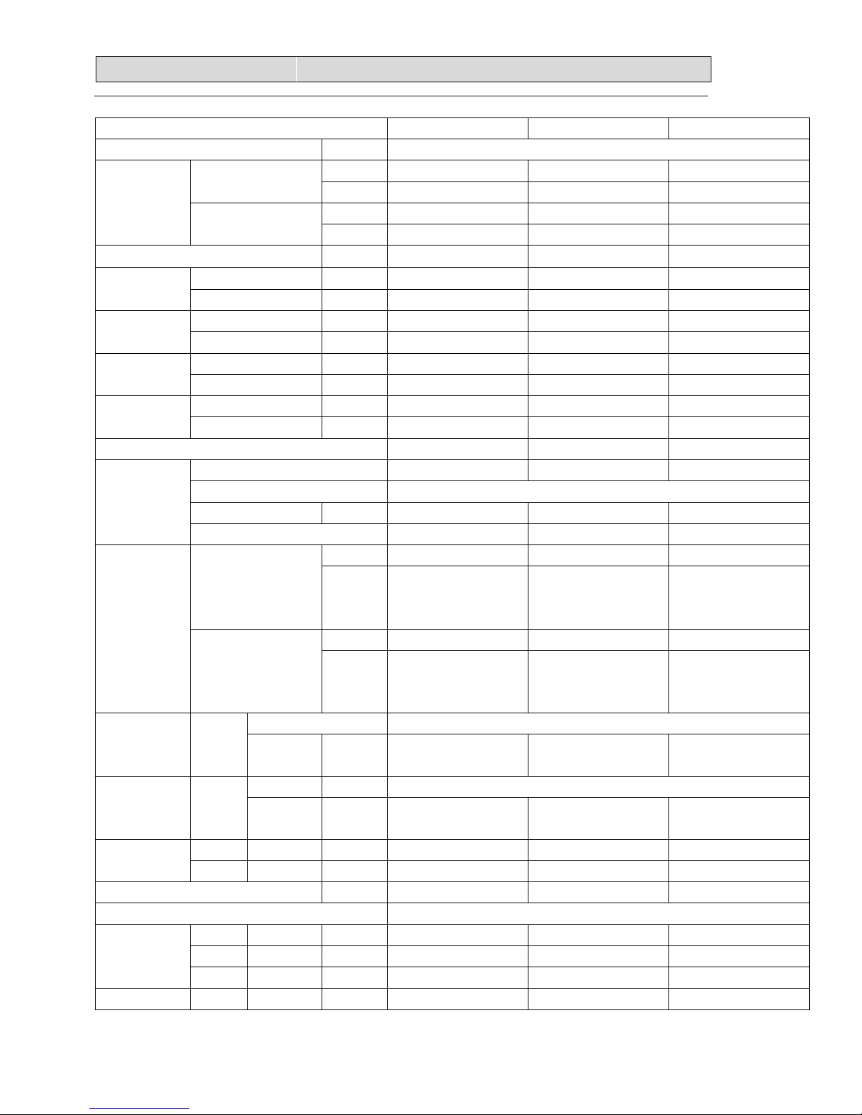
22.. SSPPEECCIIFFIICCAATTIIOONNSS
5
Model
AUD-36UX4SMH
Function Cooling Heating
Power supply 220V~240V/50Hz
Capacity
Capacity kW 10 11.5
Dehumidification l /h 3.5 ----
Air flow m3/h 1700 1800
Electrical dat
a
Running current A 1.13 1.13
Rated input kW 0.26 0.26
Auxiliary heater A ----
Power factor % ----
Starting current A ----
SEER/HSPF ----
Compressor
Model ----
Winding resistance
(at25℃)
Ω ----
Indoor
fan motor
Model Y7S423C024
Winding resistance
(at20℃)
Ω
M:23.78;A:21.48
Outdoor
fan motor
Model -----
Winding resistance
(at20℃)
Ω ----
Net size L×W×H cm
130×72×26.6
Package size L×W×H cm
156.9×86.8×33.6
Net weight kg
43
Gross weight kg
51
Refrigerant
piping
Liquid pipe mm
9.52
Gas pipe mm
15.88
Connection method
----
Special
remarks
Air direction
----
Sound level (Hi) dB
43
Fan speed (Hi) rpm
1150
Fan speed regulator
3
Refrigerant filling
capacity(R410a)
kg
----
Throttle mode
----
Page 8

22.. SSPPEECCIIFFIICCAATTIIOONNSS
6
Model AUD-48UX4SHH AUD-60UX4SHH
Function Cooling Heating Cooling Heating
Power supply 220V~240V/50Hz
Capacity
Capacity kW
12.6(5.5-13.5 15(4.0-18) 17(6.2-18) 20.5(6.4-21)
Dehumidification l /h 4.5 ---- 4.5 ----
Air flow m3/h 2000 2000 2000 2000
Electrical data
Running current A 2.0 2.0 2.0 2.0
Rated input kW 0.58 0.58 0.58 0.58
Auxiliary heater A ---- ----
Power factor % ---- ----
Starting current A ---- ----
SEER/HSPF ---- ----
Compressor
Model ---- ----
Winding resistance
(at25℃)
Ω ---- ----
Indoor
fan motor
Model Y7S423C226 Y7S423C226
Winding resistance
(at20℃)
Ω M:17.89;A:38.04 M:17.89;A:38.04
Outdoor
fan motor
Model ----- -----
Winding resistance
(at20℃)
Ω ----- ----
Net size L×W×H cm 138×80×35 138×80×35
Package size L×W×H cm 155×94×41 155×94×41
Net weight kg 50 50
Gross weight kg 58 58
Refrigerant
piping
Liquid pipe mm 9.52 9.52
Gas pipe mm 19.05 19.05
Connection method ---- ----
Special
remarks
Air direction ----
Sound level (Hi) dB 53 53
Fan speed (Hi) rpm 1250 1250
Fan speed regulator 3 3
Refrigerant filling
capacity(R410a)
kg ---- ----
Throttle mode ---- ----
Page 9

22.. SSPPEECCIIFFIICCAATTIIOONNSS
7
Model
AUC-18UX4SAA
Function Cooling Heating
Power supply 220V~240V/50Hz
Capacity
Capacity kW
5(1.87-5.75 5.6(1.38-6.6)
Dehumidification l /h 1.5 ----
Air flow m3/h 850 850
Electrical data
Running current A 0.32 0.32
Rated input kW 70 70
Auxiliary heater A ----
Power factor % ----
Starting current A ----
SEER/HSPF ----
Compressor
Model ----
Winding resistance
(at25℃)
Ω ----
Indoor
fan motor
Model YDK95-28-4-B
Winding resistance
(at20℃)
Ω M:240;A:245
Outdoor
fan motor
Model -----
Winding resistance
(at20℃)
Ω ----
Net size L×W×H cm
57x57x27(panel 65x65x3)
Package size L×W×H cm
74X67X35(panel 73X73X13)
Net weight kg 21
Gross weight kg 25.5
Refrigerant
piping
Liquid pipe mm 6.35
Gas pipe mm 12.7
Connection method
Special
remarks
Air direction ----
Sound level (Hi) dB 48
Fan speed (Hi) rpm 980
Fan speed regulator 3
Refrigerant filling
capacity(R410a)
kg
Throttle mode
Page 10

22.. SSPPEECCIIFFIICCAATTIIOONNSS
8
Model AUC-24UX4SEA
AUC-36UX4SEA
Function Cooling Heating Cooling Heating
Power supply 220V~240V/50Hz
Capacity
Capacity kW 6.4 7.0 10 11.5
Dehumidification l /h --- ---- 3.5 ----
Air flow m3/h 1100 1100 1500 1600
Electrical data
Running current A 0.4 0.4 0.96 0.96
Rated input kW 120 120 0.22 0.22
Auxiliary heater A ---- ----
Power factor % ---- ----
Starting current A ---- ----
SEER/HSPF ---- ----
Compressor
Model ---- ----
Winding resistance
(at25℃)
Ω ---- ----
Indoor
fan motor
Model ARW5901QH EHDS50AQ
Winding resistance
(at20℃)
Ω -- ----
Outdoor
fan motor
Model ----- -----
Winding resistance
(at20℃)
Ω ---- ----
Net size L×W×H cm
84x84x25(panel 95×95×3.7)
Package size L×W×H cm
93X93X29(panel 73X73X13)
Net weight kg 24 26
Gross weight kg 30 32
Refrigerant
piping
Liquid pipe mm 9.52 9.52
Gas pipe mm 15.88 15.88
Connection method FLARE
Special
remarks
Air direction ----
Sound level (Hi) dB 42 50
Fan speed (Hi) rpm 440 400 630
Fan speed regulator 3 3
Refrigerant filling
capacity(R410a)
kg ---- ---
Throttle mode ---- ---
Page 11

22.. SSPPEECCIIFFIICCAATTIIOONNSS
9
Model AUC-48UX4SFA
AUC-60UX4SFA
Function Cooling Heating Cooling Heating
Power supply 220V~240V/50Hz
Capacity
Capacity kW
12.6(5.5-13.5 15(4.0-18) 17(6.2-18
)
20(5.6-21)
Dehumidification l /h 4.5 ---- 4.5 ----
Air flow m3/h 2000 2000 2000 2000
Electrical data
Running current A 2.0 2.0 2.0 2.0
Rated input kW 0.58 0.58 0.58 0.58
Auxiliary heater A ---- ----
Power factor % ---- ----
Starting current A ---- ----
SEER/HSPF ---- ----
Compressor
Model ---- ----
Winding resistance
(at25℃)
Ω ---- ----
Indoor
fan motor
Model SIC-72FW-D8124-2B SIC-72FW-D8124-2B
Winding resistance
(at20℃)
Ω ---- ----
Outdoor
fan motor
Model ----- -----
Winding resistance
(at20℃)
Ω ---- ----
Net size L×W×H cm
84×84×30(panel 95×95×3.7)
Package size L×W×H cm
93×93×34(panel 99×101×9.5)
Net weight kg 29 29
Gross weight kg 35 35
Refrigerant
piping
Liquid pipe mm 9.52 9.52
Gas pipe mm 19.05 19.05
Connection method FLARE FLARE
Special
remarks
Air direction ----
Sound level (Hi) dB 49 49
Fan speed (Hi) rpm 630 630
Fan speed regulator 3 3
Refrigerant filling
capacity(R410a)
kg ---- ---
Throttle mode ---- ---
Page 12
22.. SSPPEECCIIFFIICCAATTIIOONNSS
10
Model AUD-18UX4SZKL1
AUD-24UX4SALH1 AUD-36UX4SAMH1
Power supply Ph-V-Hz 1N,220V~240V/50Hz
Capacity
Cooling
kW 5(1.2-6.5) 7.0(1.5-7.8) 9.2(3.6~10.5)
Btu/h 17,100(4,100-22,200) 23,900(5,100-26,600) 31,400(12,300-35,800)
Heating
kW 5.6(1.8-7.2) 8.1(1.8-10) 11.0(3.05~13.8)
Btu/h 19,100(6,100-24,600) 27,600(6,100-34,100) 37,500(10,400-47,100)
Dehumidification L/h —— —— ——
Rated input
Cooling kW 1.5(0.4-2.25) 2.3(0.40~3.6) 3.05(0.40~5.1)
Heating kW 1.6(0.38-2.15) 2.65(0.38~3.6) 3.25(0.38~5.1)
Rated Current
Cooling A 6.8 10.2 13.9
Heating A 7.3 11.5 13.1
Max. input
Cooling kW 2.5 3.6 5.1
Heating kW 2.5 3.6 5.1
Max.Current
Cooling A 12 15.9 22.5
Heating A 12 15.9 22.5
SEER/SCOP 5.6/3.8 5.6/3.8 5.1/3.8
Compressor
Model DA131S1B-28FZ DA230S2C-31MT DA250S2C-30MT
Type 2-cylinder type rotary
Winding resistance Ω 0.55(20℃) 0.73 (at20℃) 055(20℃)
Brand GMCC GMCC GMCC
Fan motor
Indoor
Model YSK110-40-4-A SIC-70CW-F195-1 SIC-101CW-F1246-1
Winding
resistance
(at20℃)
M:146;A:76 和 205 / /
Outdoor
Model ARW4401QH SIC-71FW-D8121-1
SIC-71FW-D8121-1
Winding
resistance
(at20℃)
/ / /
Fan Indoor
type centrifugal fan
Speed
Hi/Med/Low
r.p.m 850/950/1130(10Pa) 1000/910/810(30Pa) 1060/980/900(30Pa)
Fan speed Outdoor
type r.p.m tube-axial
Speed
Hi/Med/Low
r.p.m 0-810 0-810 0-810
Air circulation
Indoor Hi/Med/Low m³/h -- -- --
Outdoor Hi/Med/Low m³/h -- -- --
Static Pressure(*Default Setting) Pa 10*/30 10/30*/50/80 10/30*/50/80
Operating control Wire Remote Control
Dimensions
Indoor L×W×H mm 1170×447×190 900×720×270 900×720×270
Outdoor L×W×H mm 900×300×640 950×840×340 950×840×340
Page 13

22.. SSPPEECCIIFFIICCAATTIIOONNSS
11
Model AUD-18UX4SZKL1
AUD-24UX4SALH1 AUD-36UX4SAMH1
Packing
Indoor L×W×H mm 1340×580×236 1170×870×340 1170×870×340
Outdoor L×W×H mm 1050×400×700 1110×980×460 1110×980×460
Weight
Indoor Net/Gross kg 24/28 32/37 43/51
Outdoor Net/Gross kg 45/51 69/73 70/74
Noise lever
Indoor
Low/Hi/sound
power
Db --/41/54 --/41/54 40/45/56
Outdoor
Low/Hi/sound
power
Db 45/50/62 45/50/62 --/58/70
Refrigerant piping
Gas/Liquid mm 12.7/6.35 15.88/9.52 15.88/9.52
Max. refrigerant pipe length m 15 30 30
Max. difference in level m 7.5 15 15
Connection method Flare
Connection
wiring
Power wiring mm2 3 core x1.5 3 core x2.5 3 core x2.5
Signal wiring mm2 4 core shielded wire x 0.75
Refrigerant charge(R410a) kg 1.4 1.68 2.1
Throttle Type EEV EEV EEV
Ambient temp
℃
Cooling 15~48
Heating -10~24
Page 14
22.. SSPPEECCIIFFIICCAATTIIOONNSS
12
Model
AUC-18UR4SZAA1 AUC-24UR4SAEA1 AUC-36UR4SAEA1
Power supply Ph-V-Hz 1N,220V~240V/50Hz
Capacity
Cooling
kW 5(1.2-6.5) 7.0(2.2-8.0) 9.5(3.6~10.5)
Btu/h 17,100(4,100-22,200) 23,900(7,500-27,300) 32,400(12,300-35,800)
Heating
kW 5.6(1.8-7.2) 8.2(2.5-10) 11.0(3.05~13.8)
Btu/h 19,100(6,100-24,600) 28,000(8,500-34,100) 37,500(10,400-47,100)
Dehumidification L/h —— —— ——
Rated input
Cooling kW 1.49(0.40~2.25) 2.3(0.40~3.6) 3.07(0.4~4.2)
Heating kW 1.75(0.38~2.15) 2.73(0.38~3.6) 3.10(0.38~4.2)
Rated Current
Cooling A 6.6 10.1 13.4
Heating A 7.8 12.2 13.5
Max. input
Cooling kW 2.5 3.6 4.25
Heating kW 2.5 3.6 4.25
Max.Current
Cooling A
12 15.5 20
Heating A 12 15.5 20
SEER/SCOP 5.6/3.8 5.6/3.8 5.1/3.8
Compressor
Model DA131S1B-28FZ DA230S2C-31MT DA250S2C-30MT
Type 2-cylinder type rotary
Winding resistance Ω 0.55(20℃) 0.73 (at20℃) 055(20℃)
Brand GMCC GMCC GMCC
Fan motor
Indoor
Model EHDS50AQ ARW5901QH EHDS50AQ
Winding
resistance
(at20℃)
/ / /
Outdoor
Model ARW4401QH SIC-71FW-D8121-1
SIC-71FW-D8121-1
Winding
resistance
(at20℃)
/ / /
Fan Indoor
type
centrifugal fan
Speed
Hi/Med/Low
r.p.m 980/840/720 440/380/370 630/520/460
Fan speed Outdoor
type r.p.m tube-axial
Speed
Hi/Med/Low
r.p.m 0-810 0-810 0-810
Air circulation
Indoor Hi/Med/Low m³/h -- -- --
Outdoor Hi/Med/Low m³/h -- -- --
Static Pressure(*Default Setting) Pa 0 0 0
Operating control Wireless Remote control(J1-05)
Dimensions
Indoor L×W×H mm 650×570×270 840×840×248 840×840×248
Outdoor L×W×H mm 900×300×640 950×340×840 950×340×840
Panel L×W×H mm 650×650×30 950×950×37 950×950×37
Packing Indoor L×W×H mm 770×750×310 930×930×290 930×930×290
Page 15

22.. SSPPEECCIIFFIICCAATTIIOONNSS
13
Model
AUC-18UR4SZAA1 AUC-24UR4SAEA1 AUC-36UR4SAEA1
Outdoor L×W×H mm 1050×400×700 1110×460×980 1110×460×980
Panel L×W×H mm 730×730×130 1010×990×95 1010×990×115
Weight
Indoor Net/Gross kg 21/25.5 24/30 26/32
Outdoor Net/Gross kg 45/51 69/73 70/74
Panel Net/Gross kg 2.4/5 6/7.5 6/7.5
Noise lever
Indoor
Low/Hi/sound
power
Db --/48/58 36/42/53 --/50/61
Outdoor
Low/Hi/sound
power
Db 45/50/62 --/58/70 --/58/70
Refrigerant piping
Gas/Liquid mm 12.7/6.35 15.88/9.52 15.88/9.52
Max. refrigerant pipe
length
m
15 30 30
Max. difference in level m 7.5 15 15
Connection method Flare
Connection
wiring
Power wiring mm2 3 core x1.5 3 core x2.5 3 core x2.5
Signal wiring mm2 4 core shielded wire x 0.75
Refrigerant charge(R410a) kg 1.4 1.68 2.1
Throttle Type EEV EEV EEV
Ambient temp
℃
Cooling 15~48
Heating -10~24
NOTE :Test conditions:
Cooling : Indoor: DB27℃/ WB19℃ Outdoor: DB35℃/ WB24℃
Heating: Indoor: DB20℃/ WB15℃ Outdoor: DB7℃/ WB 6℃
Page 16

22.. SSPPEECCIIFFIICCAATTIIOONNSS
14
2-2. Major component specifications
2-2-1.INDOOR FAN MOTOR
ELECTRIC
PERFORMANCE
PAR AMET ER
AUD-18UX4SKL
AUD-24UX4SLH
Motor model YSK110-40-4-A Y6S419C56
Rated power source
220V~ 50Hz
220V 50HZ
Phases/Poles 1/4 1/4
Rated load output(W) ---- 25
Rated speed(r/min)
1130/950/850(高/中/低)
1270
Ambient
temperature( )℃
-5℃~+43℃ -5℃~+43 .℃
ELECTRIC
PERFORMANCE
PAR AMET ER
AUD-36UX4SMH
AUD-48UX4SHH
AUD-60UX4SHH
Motor model Y7S423C024 Y7S423C226
Rated power source 220-240V 50Hz 220-240V 50Hz
Phases/Poles 1/4 1/4
Rated load output(W) 260 280
Rated speed(r/min)
1020/1070/1150 (White)
1190/1230/1280 (Red)
1020/1070/1150 (White)
1190/1230/1280 (Red)
Ambient
temperature( )℃
-5℃~+43 .℃ -5℃~+43 .℃
ELECTRIC
PERFORMANCE
PAR AMET ER
AUC-18UX4SAA AUC-24UX4SEA
Motor model YDK95-28-4-B ARW5901QH
Rated power source
220V~ 50Hz
220V 50Hz
Phases/Poles 1/4 1/4
Rated load output(W)
28(高档)
42
Rated speed(r/min)
980/840/720(高/中/低)
440/400/370
Ambient
temperature( )℃
-5℃~+43℃. -5℃~+43℃
Page 17
22.. SSPPEECCIIFFIICCAATTIIOONNSS
15
ELECTRIC
PERFORMANCE
PAR AMET ER
AUC-36UX4SEA
AUC-48UX4SFA
AUC-60UX4SFA
Motor model EHDS50AQ SIC-72FW-D8124-2B
Rated power source 220-240V 50Hz 220-240V 50Hz
Phases/Poles -- --
Rated load output(W) 0.22 124
Rated speed(r/min)
460/520/630 460/520/630
Ambient
temperature( )℃
-5℃~+43 .℃ -5℃~+43 .℃
2-2-2 OUTDOOR FAN MOTOR
ELECTRIC PERFORMANCE
AUW-18U4SG AUW-24U4SZ AUW-36U4SA
Motor model YDK29-6I-22 YDK70-6H-3 YDK95-6-9043
Rated power source
220V~ 50Hz
220V 50Hz 220-240V 50Hz
Phases /Poles 1/6 1/6 1/6
Rated load output(W) 28 65 95
Ambient temperature( )℃
-5℃~+43℃ -5℃~+43℃ -5℃~+43℃
ELECTRIC PERFORMANCE
AUW-48U6SP AUW-60U6SP
Motor model YDK65-6-9024
YDK65-6-9061
YDK65-6-9024
YDK65-6-9061
Rated power source
220V~ 50Hz 220V~ 50Hz
Phases /Poles 1/6 1/6
Rated load output(W) 65 65
Ambient temperature( )℃
-5℃~+43℃ -5℃~+43℃
Page 18
22.. SSPPEECCIIFFIICCAATTIIOONNSS
16
2-2-3. COMPRESSOR
ELECTRIC
PERFORMANCE
AUW-18U4SG
AUW-24U4SZ
AUW-36U4SA
Compressor model DA130S1C-20FZ ATL165SD-C9AU DA250S2C-30MT
Compressor type Rotary Rotary Rotary
Rated power 990W 1550W 2120W
Current (A) 4.97 10.7 8.85
Motor Motor type DC brushless motor DC brushless motor DC brushless
motor
Starting type DC Inverter DC Inverter DC Inverter
Winding
resistance
0.95/0.95/0.95
Ω(at 75 )℃
U-V/V-W/W-U
0.49/0.49/0.49Ω(at
25 )℃
U-V/V-W/W-U
0.55/0.55/0.55Ω(at
20 )℃
U-V/V-W/W-U
Number of cylinder 2 2 4
Oil type ESTER OIL VG74 HAF68D1C ESTER OIL VG74
Oil charge (cc) 500 880 820
Ambient
temperature( )℃
-5℃~+43 .℃ -5℃~+43℃ -5℃~+43℃
ELECTRIC
PERFORMANCE
AUW-48U6SP
AUW-60U6SP
Compressor model TNB306FPNMC LNB42FSAMC
Compressor type Rotary Rotary
Rated power 3010W 4270W
Current (A) 9.3 12.0
Motor Motor type DC brushless motor DC brushless motor
Starting type DC Inverter DC Inverter
Winding
resistance
1.02
Ω(at 20 )℃
U-V/V-W/W-U
0.53Ω(at 20 )℃
U-V/V-W/W-U
Number of cylinder 2 3
Oil type PVE(FV50S) PVE(FV50S)
Oil charge (cc) 870 1400
Ambient
temperature( )℃
-5℃~+43 .℃ -5℃~+43℃
Page 19

22.. SSPPEECCIIFFIICCAATTIIOONNSS
17
2-3. Other component specifications
2-3-1. INDUCTANCE
ELECTRIC
PERFORMANCE
PAR AMET ER
AUW-18U4SG AUW-24U4SZ
Inductance model R2050HSA R2550HSA
Rated power source 220V 50Hz 220-240V 50Hz
Rated current(A) 20 25
Rated inductance 5.0(mH)±10% 5.0(mH)±10%
Ambient temperature( )℃
-20℃~+70 .℃ -20℃~+70 .℃
ELECTRIC
PERFORMANCE
PAR AMET ER
AUW-36U4SA
AUW-48U6SP
AUW-60U6SP
Inductance model R2550HSA R3010HX-2
Rated power source 220-240V 50Hz 380V 50/60Hz
Rated current(A) 25 30
Rated inductance 5.0(mH)±10% 1.0(mH)±10%
Ambient temperature( )℃
-20℃~+70 .℃ -20℃~+60 .℃
2-3-2. FILT ER
ELECTRIC
PERFORMANCE
AUW-18U4SG AUW-24U4SZ AUW-36U4SA
Filter model RTNF250-25T068X RTNF-250T10X-3LF RTNF250-30T10X-3LF
Rated current(A) 20 20 30
Rated power source AC 220V 50/60Hz AC 220V—50/60Hz AC 220V—50Hz
Filter frequency range 150K—30MHz 150K—30MHz 150K—30MHz
Temperature
range( )℃
-25℃~+85 .℃ -25℃~+55 .℃ -25℃~+85 .℃
ELECTRIC
PERFORMANCE
AUW-48U6SP AUW-60U6SP
Filter model EFFQ-27TT-06 EFFQ-27TT-06
Rated current(A) 27 27
Rated power source 380V 50/60Hz 380 50/60Hz
Filter frequency range 150K—30MHz 150K—30MHz
Temperature
range( )℃
-25℃~+65 .℃ -25℃~+65 .℃
Page 20
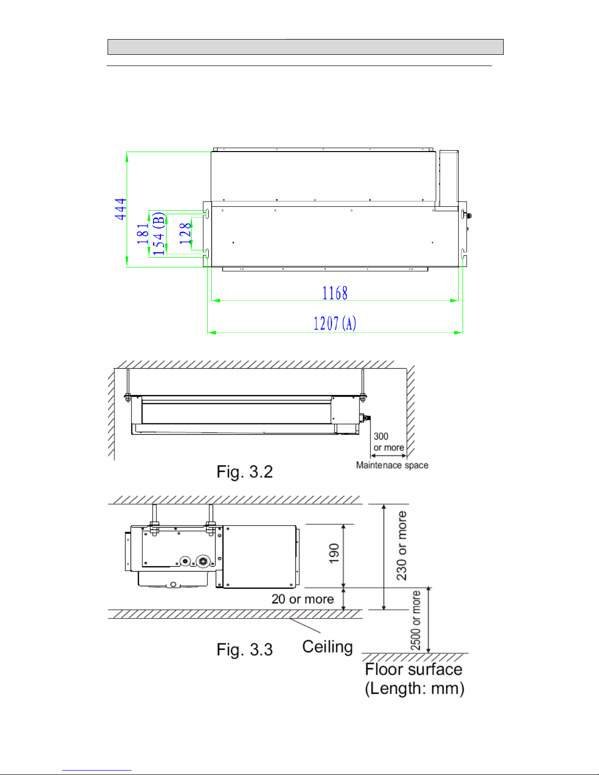
33.. OOUUTTLLIINNEESS AANNDD DDIIMMEENNSSIIOO
18
3-1. INDOOR
(
MODEL: AUD-18UX4SGKL、AUD-18UX4SZKL1 )
Page 21

33.. OOUUTTLLIINNEESS AANNDD DDIIMMEENNSSIIOO
19
(
MODEL: AUD-24UX4SLH、AUD-24UX4SALH1)
A(mm) B(mm) C(mm) D(mm)
934 668 898 722
(
MODEL: AUD-36UX4SMH、AUD-36UX4SAMH1)
A(mm) B(mm) C(mm) D(mm)
1344 668 1297 722
Page 22

33.. OOUUTTLLIINNEESS AANNDD DDIIMMEENNSSIIOO
20
(
MODEL: AUD-48UX4SHH、AUD-60UX4SHH)
A(mm) B(mm) C(mm) D(mm)
1344 740 1297 796
Page 23
33.. OOUUTTLLIINNEESS AANNDD DDIIMMEENNSSIIOO
21
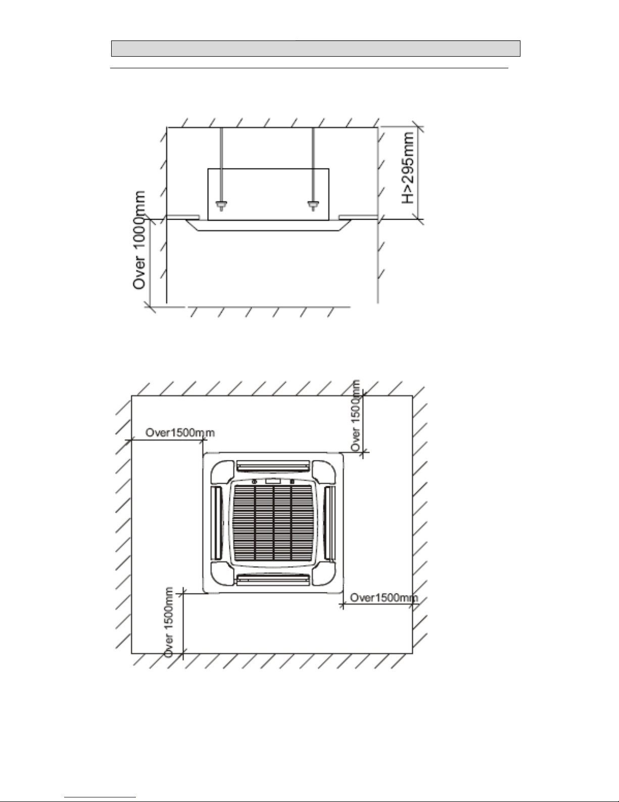
(
MODEL: AUC-18UX4SGAA、AUC-18UR4SZAA1)
Page 24

33.. OOUUTTLLIINNEESS AANNDD DDIIMMEENNSSIIOO
22
(
MODEL: AUC-24UX4SEA、AUC-36UX4SEA、AUC-48UX4SFA
、
AUC-60UX4SFA、AUC-24UR4SAEA1、AUC-36UR4SAEA1)
Page 25

33.. OOUUTTLLIINNEESS AANNDD DDIIMMEENNSSIIOO
23
3-2.OUTDOOR
(
MODEL: AUW-18U4SG)
Page 26

33.. OOUUTTLLIINNEESS AANNDD DDIIMMEENNSSIIOO
24
(
MODEL: AUW-24U4SZ、AUW-18U4SZ1)
Page 27

33.. OOUUTTLLIINNEESS AANNDD DDIIMMEENNSSIIOO
25
(
MODEL: AUW-36U4SA、AUW-24U4SA1、AUW-36U4SA1)
Page 28

33.. OOUUTTLLIINNEESS AANNDD DDIIMMEENNSSIIOO
26
(
MODEL: AUW-48U6SP、AUW-60U6SP)
1386
1090
950
580
380
410
>100mm
>100mm
>300mm
>500mm
Page 29

44.. RREEFFRRIIGGEERRAANNTT FFLLOOWW DDIIAAGGRRAAM
M
27
4-1. Refrigerant flow diagram :
For 18k,24k,36k type
Compreesor
4-way vavle
EEVB
Stop vavle
Outdoor heat excharger
Indoor heat excharger
Stop vavle
Outdoor unitIndoor unit
Remark:
COOLING CYCLE
HEATING CYCLE
Page 30

44.. RREEFFRRIIGGEERRAANNTT FFLLOOWW DDIIAAGGRRAAM
M
28
MODEL:AUD-48UX6SPHH、AUD-60UX6SPHH
AUC-48UX6SPFA、AUC-60UX6SPFA
EEV
Compressor
Outdoor heat exchange
Indoor heat exchange
4-Way valve
Stop valve(3/8)
Remark: cooling cycle
heating cycle
Stop valve(3/4)
HP
LP
SC
Strainer
Strainer
A
ccumulator
Page 31

44.. RREEFFRRIIGGEERRAANNTT FFLLOOWW DDIIAAGGRRAAM
M
29
Evacuation procedures:
EVACUATION PROCEDURES
Connect the refrigerant pipes (both the liquid an
d
g
as pipes) between the indoor and the outdoor units.
Remove service port cap of the stop valve A and connect gage manifold valve and vacuu
m
p
ump to it.
Run the vacuum pump for more than 15 minutes and at this time confirm that the pressure
gage indicates -0.1Mpa(-76 cmHg).
Stop pump and keep the pressure for one or two minutes. Make sure the pressure is no
change(if the pressure is changed to high, there is some leakage for the pipe connection).
Remove gage manifold valve quickly from the service port of the stop valve A.
full open the stop valves A on gas and liquid pipe sides.
T ot al pi pe len gth is in the range :
N
o gas charge is needed
T ot al pipe length exceeding the limit:
Charge the prescribed amount of gas.
Tighten the cap to the service port to obtain the initial status.
Retighten the cap.
Leak test
Repeat the steps above for other valves(B\C\D), be sure all refrigerant pipes are
connected and evacuated, and all valves are full opend.
Page 32

44.. RREEFFRRIIGGEERRAANNTT FFLLOOWW DDIIAAGGRRAAM
M
30
4-3. Evacuation direction:
MAX. Refrigerant pipe length and height difference:
AUD-18UX4SGKL
AUC-18UX4SGAA
AUC-18UR4SZAA1
AUD-18UX4SZKL1
AUD-24UX4SZLH
AUC-24UX4SZEA
AUD-36UX4SAMH
AUC-36UX4SAEA
AUC-24UR4SAEA1
AUC-36UR4SAEA1
AUD-24UX4SALH1
AUD-36UX4SAMH1
Pipe length 15m 20m 30m
Height difference 7.5m 10m 15m
AUD-48UX6SPHH
AUC-48UX6SPFA
AUD-60UX6SPHH
AUC-60UX6SPFA
Pipe length 50m 50m
Height difference 15m 15m
*Do your best to reduce the pipe length. Long pipe may cause capacity of the indoor unit incline.
Outdoor unit precharged
Total refrigerant pipe length
0m~5m
5m~60m
AUW-18U4SG
1270g 0g
For 18k:
Xg = 15g / m × (Total pipe length(m) -5)
For 24k/36K/48K/60K:
Xg =35g / m × (Total pipe length(m) -5)
AUW-18U4SZ1
1400g 0g
AUW-24U4SZ
1500g 0g
AUW-24U4SA1
1680g 0g
AUW-36U4SA
2100g 0g
AUW-36U4SA1
2100g 0g
AUW-48U6SP
3000g 0g
AUW-60U6SP
3500g 0g
Page 33

55.. EELLEECCTTRRIICCAALL DDAATTAA
31
5-1.Electrical wiring diagrams
INDOOR:AUD-18UX4SKL
4(SI)
2(N)
1(L)
1
2
2
1
Room
CN23
CN24
Coil
1
2
2
1
CN8(SI)
CN2(NIN)
CN1(LIN)
2121
434
3
FM
CN10
Fan
1
2
2
1
Wind
CN6
CN9
Pump
1
2
2
1
Water Level Switch
Wired Con
343
4
121
2
Water
CN22
CN4
10
Out Input
CN20
3
3
2
1
2
1
Fan_Pro
1
2
2
1
1
2
1
2
3
3
CN3
Main Control
Board
Trans
Trans
Room Sensor
Coil Sensor
Fan-N
1
2
2
1
1
2
2
1
CN25
Disp
Red Connector(High Static Pressu re
)
CN5
CN12
Transformer
Pump
Fresh Air
Outside Input
Motor
White Connector(Low Static Press ure
)
Fan Motor
Fan Capacitor
CN1
Display Board
Wired
Controller
Teminal Panel
to Outdoor Unit
Electrical Wiring Diagram 1465113.A
Attention:
1.The fan motor connection mode has been setted by it's product factory.
Please according to specification to connect different static pressure connector.
Red
Red
Exchange
White
White
RED
BLU
BRN
BLACK
BLU
BRN
Y/G
CN18
AUD-18UX4SKL1
4(SI)
2(N)
1(L)
1
2
2
1
Room
CN23
CN24
Coil
1
2
2
1
CN8(SI)
CN2(NIN)
CN1(LIN)
212
1
434
3
FM
CN10
Fan
1
2
2
1
Wind
CN6
CN9
Pump
1
2
2
1
Water Level Switch
Wired Con
343
4
121
2
Water
CN22
CN4
10
Out Input
CN20
3
3
2
1
2
1
Fan_Pro
1
2
2
1
1
2
1
2
3
3
CN3
Main Control
Board
Trans
Trans
Room Sensor
Coil Sensor
Fan-N
1
2
2
1
1
2
2
1
CN25
Disp
Red Connector(High Static Pressu re
)
CN5
CN12
Transformer
Pump
Fresh Air
Outside Input
Motor
White Connector(Low Static Press ure
)
Fan Motor
Fan Capacitor
CN1
Display Board
Wired
Controller
Teminal Panel
to Outdoor Unit
Electrical Wiring Diagram 1465113.A
Attention:
1.The fan motor connection mode has been setted by it's product factory.
Please according to specification to connect different static pressure connector.
Red
Red
Exchange
White
White
RED
BLU
BRN
BLACK
BLU
BRN
Y/G
CN18
Page 34

55.. EELLEECCTTRRIICCAALL DDAATTAA
32
AUD-24UX4SLH:
1
2
2
1
ROOM
CN23
CN24
COIL
1
2
2
1
CN8(SI)
CN2(NIN)
CN1(LIN)
21
2
1
434
3
FM
CN10
1
2
2
1
WIND
CN6
CN9
PUMP
1
2
2
1
Water level switch
WIRED CON
CN18
343
4
1212
WATER
CN22
CN4
212
1
434
3
CN14
RY-HEAT
10
OUT INPUT
CN20
3
3
2
1
2
1
FAN_PRO
1
2
2
1
1
2
1
23
3
Electric wiring diagram
1468270.
B
CN5
TRANS
CN12
TRANS
Transformer
Coil temperature sensor
Room temperature sensor
Outside input
Main control
board
Wire remote
controller
Display board
CN1
DISP
CN25
Fan capacitor
Fan motor
Terminal panel To outdoor unit
RED
BLU
BRN
BLK
BLU
BRN
YEL/GRN
White connector
(
50Pa
)
Red connector(80Pa)
1
2
2
1
1
2
2
1
NOTE:
Fan motor connector in the diagram is the factory default configuration.
In actual use,please select the right connector according to the the value of the static
pressure.
1(L)
2(N)
4(SI)
AUD-24UX4SLH
AUD-24UX4SLH1、AUD-36UX4SMH1:
1
2
2
1
ROOM
CN11
CN12
COIL
1
2
2
1
CN1(SI)
CN3(NIN)
CN2(LIN)
212
1
434
3
CN15
1
2
2
1
WIND
CN10
CN9
PUMP
1
2
2
1
Water level switch
WIRED CON
CN6
34
34
12
1
2
WATER
CN17
212
1
43
4
3
CN5
RY-HEAT
100
10
OUT INPUT
CN16
3
3
2
1
2
1
1
2
1
23
3
Electric wiring diagram
1518321.
B
Coil temperature sensor
Room temperature sensor
Outside input
Main control
board
Wire remote
controller
Display board
CN1
DISP
CN7
Terminal panel To outdoor unit
RED
BLU
BRN
BLK
BLU
BRN
YEL/GRN
1(L)
2(N)
4(SI)
5
5
212
1
4343
5
5
CN8
6
6
DC motor
FG
Vsp
VCC
GND
VDD
DCFAN
STEP MOTOR
CN18
YEL/GRN
Page 35

55.. EELLEECCTTRRIICCAALL DDAATTAA
33
AUD-36UX4SAMH
1
2
2
1
ROOM
CN23
CN24
COIL
1
2
2
1
CN8(SI)
CN2(NIN)
CN1(LIN)
212
1
434
3
FM
CN10
1
2
2
1
WIND
CN6
CN9
PUMP
1
2
2
1
Water level switch
WIRED CON
CN18
343
4
121
2
WATER
CN22
CN4
212
1
434
3
CN14
RY-HEAT
10
OUT INPUT
CN20
3
32
1
2
1
FAN_PRO
1
2
2
1
1
2
1
2
3
3
Electric wiring diagram
1468270.
B
CN5
TRANS
CN12
TRANS
Transformer
Coil temperature sensor
Room temperature sensor
Outside input
Main control
board
Wire remote
controller
Display board
CN1
DISP
CN25
Fan capacitor
Fan motor
Terminal panel To outdoor unit
RED
BLU
BRN
BLK
BLU
BRN
YEL/GRN
White connector
(
50Pa
)
Red connector(80Pa)
1
2
2
1
1
2
2
1
NOTE:
Fan motor connector in the diagram is the factory default c onfig uration.
In actual use,please select the right connector according to the the value of the static
pressure.
1(L)
2(N)
4(SI)
AUD-48UX4SHH、AUD-60UX4SHH
1
2
2
1
ROOM
CN23
CN24
COIL
1
2
2
1
CN8(SI)
CN2(NIN)
CN1(LIN)
212
1
434
3
FM
CN10
1
2
2
1
WIND
CN6
CN9
PUMP
1
2
2
1
Water level switch
WIRED CON
CN18
343
4
121
2
WATER
CN22
CN4
212
1
434
3
CN14
RY-HEAT
10
OUT INPUT
CN20
3
3
2
1
2
1
FAN_PRO
1
2
2
1
1
2
1
2
3
3
Electric wiring diagram
1493068.
A
CN5
TRANS
CN12
TRANS
Transformer
Coil temperature sensor
Room temperature sensor
Outside input
Main control
board
Wire remote
controller
Display board
CN1
DISP
CN25
Fan capacitor
Fan motor
Terminal panel To outdoor unit
RED
BLU
BRN
BLK
BLU
BRN
YEL/GRN
White connector
(
80Pa
)
Red connector( 120Pa)
1
2
2
1
1
2
2
1
NOTE:
Fan motor connector in the diagr am is the factory default co nfig uration.
In actual use,please select the right connector according to the the value of the static
pressure.
1(L)
2(N)
4(SI)
RED
WHITE
Page 36

55.. EELLEECCTTRRIICCAALL DDAATTAA
34
AUC-18UX4SAA
Page 37

55.. EELLEECCTTRRIICCAALL DDAATTAA
35
AUC-18UR4SAA1
1
2
2
1
ROOM
CN23
CN24
COIL
1
2
2
1
CN8(SI)
CN2(NIN)
CN1(LIN)
212
1
434
3
FM
CN10
1
2
2
1
CN6
CN9
PUMP
1
2
2
1
Water level switch
WIRED CON
CN18
343
4
121
2
WATER
CN22
CN4
212
1
434
3
CN14
RY-HEAT
10
OUT INPUT
CN20
3
3
2
1
2
1
FAN_PRO
1
2
2
1
1
2
1
2
3
3
Electric wiring diagram
1508920.
B
CN5
TRANS
CN12
TRANS
Transformer
Coil temperature sensor
Room temperature sensor
Outside input
Main control
board
Wire remote
controller
Display board
CN1
DISP
CN25
Fan capacitor
Fan motor
Terminal panel To outdoor unit
RED
BLU
BRN
YEL/GRN
1
2
2
1
1
2
2
1
1(L)
2(N)
4(SI)
RED
WHITE
AC FAN
Pump motor
Motor
CN19
STEP
Step motor1
Step motor2
Step motor3
Step motor4
AUC-24UX4SEA、AUC-36UX4SEA:
1
2
2
1
ROOM
CN23
CN24
COIL
1
2
2
1
1
2
2
1
WIND
CN6
CN9
PUMP
1
2
2
1
Water level switch
WIRED CON
CN18
343
4
121
2
1
2
2
1
WATER
CN22
CN4
Dc fan motor power board
CN1(LIN)
CN2(NIN)
GND(CN3)
NIN(CN2)
LIN(CN1)
CN8(SI)
DC FAN
3
CN27
DC motor
VDC (CN5.6)
GND (CN5.4)
VCC (CN5.3)
Vsp (CN5.2)
FG (CN5.1)
FG
Vsp
VCC
GND
VDD
10
1
2
1
2
3
3
CN20
OUT INPUT
CN19
STEP
5
Step motor1
Electric wiring diagram
1468272.A
Main control board
TRANS
CN12
CN5
TRANS
Transformer
1
2
2
1
1
2
2
1
Pump motor
Outside input
Step motor2
Step motor3
Step motor4
BRN
BLU
RED
BRN
BLU
BRN
BLU
BLK
YEL/GRN
To outdoor unit
Teminal panel
Wire remot e
controller
Display board
CN1
CN25
Room temperature sensor
Coil temperature sensor
Motor
1(L)
2(N)
4(SI)
Page 38

55.. EELLEECCTTRRIICCAALL DDAATTAA
36
AUC-24UR4SEA1、AUC-36UR4SEA1:
1
2
2
1
ROOM
CN23
CN24
COIL
1
2
2
1
1
2
2
1
WIND
CN6
CN9
PUMP
1
2
2
1
Water level switch
WIRED CON
CN18
343
4
121
2
1
2
2
1
WATER
CN22
CN4
Dc fan motor power board
CN1(LIN)
CN2(NIN)
GND(CN3)
NIN(CN2)
LIN(CN1)
CN8(SI)
DC FAN
3
CN27
DC motor
VDC (CN5.6)
GND (CN5.4)
VCC (CN5.3)
Vsp (CN5.2)
FG (CN5.1)
FG
Vsp
VCC
GND
VDD
10
1
2
1
2
3
3
CN20
OUT INPUT
CN19
STEP
5
Step motor1
Electric wiring diagram
1468272.A
Main control board
TRANS
CN12
CN5
TRANS
Transformer
1
2
2
1
1
2
2
1
Pump motor
Outside input
Step motor2
Step motor3
Step motor4
BRN
BLU
RED
BRN
BLU
BRN
BLU
BLK
YEL/GRN
To outdoor unit
Teminal panel
Wire remote
controller
Display board
CN1
CN25
Room temperature sensor
Coil temperature sensor
Motor
1(L)
2(N)
4(SI)
AUC-48UX4SFA、AUC-60UX4SFA
1
2
2
1
ROOM
CN23
CN24
COIL
1
2
2
1
1
2
2
1
WIND
CN6
CN9
PUMP
1
2
2
1
Water level switch
WIRED CON
CN18
343
4
121
2
1
2
2
1
WATER
CN22
CN4
Dc fan motor power board
CN1(LIN)
CN2(NIN)
GND(CN3)
NIN(CN2)
LIN(CN1)
CN8(SI)
DC FAN
3
CN27
DC motor
VDC (CN5.6)
GND (CN5.4)
VCC (CN5.3)
Vsp (CN5.2)
FG (CN5.1)
FG
Vsp
VCC
GND
VDD
10
1
2
1
2
3
3
CN20
OUT INPUT
CN19
STEP
5
Step motor1
Electric wiring diagram
1468272.A
Main control board
TRANS
CN12
CN5
TRANS
Transformer
1
2
2
1
1
2
2
1
Pump motor
Outside input
Step motor2
Step motor3
Step motor4
BRN
BLU
RED
BRN
BLU
BRN
BLU
BLK
YEL/GRN
To outdoor unit
Teminal panel
Wire remote
controller
Display board
CN1
CN25
Room temperature sensor
Coil temperature sensor
Motor
1(L)
2(N)
4(SI)
Page 39

55.. EELLEECCTTRRIICCAALL DDAATTAA
37
OUTDOOR:
AUW-18U4SG
1(L)
2(N)
YEL/GRN
PANEL
TERMINAL
CONNECTION
1(L)
2(N)
3( )
YEL/GRN
PANEL
TERMINAL
POWER
4(
SI
)
AC N OUT
AC N IN
AC L OUT
AC L IN
FILTER
SV (CN7)
4-WAY VALVE
EARTH
N
HML
C
H(CN26.4)
M(CN26.3)
L(CN26.2)
CAP(CN26.1)
N(CN26.5)
AC FAN
YEL/GRN
CN10
CN11
6
ELECTRONIC
EXPANSION VALVE A
T-COIL T-SUC T-OUT
1
2
1
2
3
3
4
4
5
5
6
6
1
1
2
2
3
45
6
345
6
1
2
2
1
T-LiqA GasA
T-DISS
L2 (CN12)
L1(CN11)
EARTH
W
V
U
UVW
CN6.1
CN6.2
CN6.3
CN7.5
CN7.4
CN7.3
CN7.2
CN7.1
CN25.1
CN25.2
CN25.3
CN25.4
CN25.5
CN2.1
CN2.2
CN2.3
N
CAP+(CN13)
BRN
+
DC+(CN8)
NOUT(CN1)
LOUT(RL1)
AC N IN(CN10)
P
DC-(CN9)
ELECTROLYTI C
AC L IN(CN9)
COMPRESSOR
YEL/GRN
RED
WHT
BLU
ELECTRIC WIRING DIAGRAM
YEL/GRN
CONDENSER
TERMINAL PANL
LIN (CN6)
NIN (CN4)
DC+(CN8)
CN20
CN22
CN21
BRN
CAPACITOR
BLU
BLU
BRN
RED
BLU
ORG
BRN
BRN
BLK
BRN
BLU
RED
BRN
BLK
SI-N(CN16)
SI-A(CN15)
SI-B(CN18)
1466720.B
INDUCTOR
BLU
EARTH(CN3)
YEL/GRN
CN19
OVERLOAD
PROTECTOR
AUW-18U4SZ1
1518965.A
SI
CN22
CN21
SV
VALUE
BLU
BLK
1
1
2
2
3
3
4
4
5
5
+
BRN
ORG
113
2
3
2
CN24
-
CN6
BLUWHT
CN101
CN102
IPM BOARD
CN103 P
CN204
CN203 L2
CN202 L1
CN104 N
CN100
RED
C
N
3
0
2
C
N
3
0
1
CN200 L
CN201 N
U
V
W
RED
LOUT1
NOUT
( )
(N)
(L)
YEL/GRN
LIN
NIN
4(SI)
1(L
2(N)
SI-N
CN4
CN5
CN1
CN2
CN7
CN3
CN10
CN23
CN17
CN18CN15
DC-
DC+
CN200
CN201
BRN
BLK
BLU
RED
BLU
COMPRESSOR
CM
BRN
BLU
RED
ELECTROLYTIC
CAPACITOR
INDUCTOR
YEL/GRN
YEL/GRN
T-COIL T-
DEF
T-OUT
T-SUCT-DISS IPM-SI POWER
PANEL
TERMINAL
POWER
CONNECTION
TERMINAL
PANEL
FILTER
E
lectric Wiring Diagram
BRN
BLU
BRN
BLK
CN28
CN26
CN27
BRN
BLU
DC FAN1
SV
FM
M
Control board
Condenser fixing
plate
Page 40

55.. EELLEECCTTRRIICCAALL DDAATTAA
38
AUW-24U4SZ
1(L)
2(N)
YEL/GRN
PANEL
TERMINAL
CONNECTION
1(L)
2(N)
3( )
YEL/GRN
PANEL
TERMINAL
POWER
4(
SI
)
AC N OUT
AC N IN
AC L OUT
AC L IN
FILTER
SV (CN7)
4-WAY VALVE
AC FAN
CN10
CN11
6
ELECTRONIC
EXPANSION VALVE A
T-COIL T-SUC T-OUT
1
2
1
2
3
3
4
4
5
5
6
6
1
1
2
2
3
45
6
34
5
6
1
2
2
1
T-Liq T-Gas
T-DISS
L2 (CN202)
L1(CN203)
EARTH
W
V
U
UVW
CN302.1
CN302.2
CN302.3
CN301.5
CN301.4
CN301.3
CN301.2
CN301.1
CN25.1
CN25.2
CN25.3
CN25.4
CN25.5
CN2.1
CN2.2
CN2.3
N(CN104)
CAP+(CN204)
BLK
+
DC+(CN8)
NOUT(CN1)
LOUT(RL1)
AC N IN(CN201)
P(CN103)
DC-(CN9)
ELECTROLYTIC
AC L IN(CN200)
COMPRESSOR
YEL/GRN
RED
WHT
BLU
ELECTRIC WIRING DIAGRAM
YEL/GRN
CONDENSER
TERMINAL PANL
LIN (CN6)
NIN (CN4)
DC+(CN8)
CN20
CN22
CN21
BLK
CAPACITOR
BLU BLU
BLK
BRN
BLU
ORG
BRN
BRN
BLK
BRN
BLU
BLK
BRN
BLK
SI-N(CN16)
SI-A(CN15)
SI-B(CN18)
1466882.A
INDUCTOR
BLU
EARTH(CN3)
YEL/GRN
BRN
YEL
4.0UF/450V
EARTH
L
M
H
N
YEL/GRN
M(CN26.3)
H(CN26.4)
N(CN26.1)
L(CN26.2)
(CN100)(CN101)
(CN102)
CN28
CN29
1
2
2
1
CN23
CN27
CN19
FG (CN13.1)
Vsp (CN13.2)
VCC (CN13.3)
GND (CN13.4)
VDC (CN13.6)
OVERLOAD
PROTECTOR
AUW-24U4SZ
Page 41

55.. EELLEECCTTRRIICCAALL DDAATTAA
39
AUW-24U4SA1、AUW-36U4SA1
1519694.A
SI
CN22
CN21
TEST
CN16
SV
VALUE
CONTROL BOARD
WHT
BLK
1
1
2
2
3
3
4
4
5
5
+
BRN
ORG
113
2
3
2
CN24-CN6
BLUWHT
CN101
CN102
IPM BOARD
CN103 P
CN204
CN203 L2
CN202 L1
CN104 N
CN100
RED
C
N
3
0
2
C
N
3
0
1
CN200 L
CN201 N
U
V
W
BLK
LOUT1
NOUT
( )
(N)
(L)
YEL/GRN
LIN
NIN
4(SI)
1(L
2(N)
SI-N
CN4
CN5
CN1
CN2
CN7
CN3
CN10
CN11
CN14
CN23
CN20
CN17
CN18CN15
CN19
CN9
CN8
DC-
DC+
CN200
CN201
BRN
BLU
BLU
RED
BLU
COMPRESSOR
CM
YEL/GRN
BRN
WHT
BLK
ELECTROLYTIC
CAPACITOR
INDUCTOR
YEL/GRN
YEL/GRN
4-WAY VALVE
ELECTRONIC
EXPANSION VALVE A
T-COIL T-
DEF
T-
OUT
T-
SUC
T-
DISS IPM-SI POWER
H-PRESS
CN12
CN13
PANEL
TERMINAL
POWER
CONNECTION
TERMINAL
PANEL
FILTER
E
lectric Wiring Diagram
HEATER
BRN
BLU
BRN
BLU
CN28
CN26
CN27
BRN
BLU
DC motor
FG
Vsp
VCC
GND
VDD
DC FAN
AUW-36U4SA
Page 42

55.. EELLEECCTTRRIICCAALL DDAATTAA
40
AUW-48U6SP、AUW-60U6SP
L1
L2
L3
N
E
N'
L3'
L2'
L1'
M
Main Control Board
Filter
Board
(W)
(V)
Power terminal panel
3N~ 380V 50Hz
(N)
( )
(U)
E
2(N)
1(L)
4(SI)
CN22
CN23
CN24
IPM-SI
CN33
CN25
SI
CN10
CN4
RY2
L1 L2
Inductor
RY1
CN10
ACIN
CN24
M
Compressor
Driver Board
SV
CN7
PTC
CN6
CN22
FAN-DOWN
CN23
FAN-UP
CN26
HEAT-L
CN27
HEAT-N
FUSE2
BRN
WHT
FUSE1
WHT
BLK
BRN
BLU
YEL/GRN
Tranformer
Terminal panel
TRANSTRANS
CN35
SI
CN34
SI-N
CN21
Power
BRN
WHT
BLK
4
3
2
1
321
4
M
4
3
2
1
321
4
12
12
12
12
CN13
H-PRESS
12
12
CN17
L-PRESS
12
12
CN16
TEST
CN14
DISS
12
12
CN18
SUC
12
12
CN15
OUTDOOR
4321
321
4
COIL
DEF
6
6
543
21
321
5
4
12
12
12
12
SV
1
1
2
2
3
3
4
4
BRN
BLU
12
12
12
12
543
21
321
5
4
543
21
321
5
4
U
V
W
BLU
BLK
RED
WHT
BLU
Electric Wiring Diagram 1469932.A
BLU
CN13
CN14
CN15
CN20
CN21
CN18
CN19
12
12
M
YEL/GRN
YEL/GRN
BLK
CN5
VALVE
Capacitor Capacitor
discharge
sensor
suction
sensor
coil
sensor
defrost
sensor
ambient
sensor
crankcase
heater
high
pressure
switch
low
pressure
switch
electronic expansion valve
BRN
BRN
BRN
WHT
WHT
Page 43

55.. EELLEECCTTRRIICCAALL DDAATTAA
41
5-2. Electric control
1. Indoor control board for indoor unit
1) AUD-18UX4SKL 、 AUD-24UX4SLH 、 AUC-24UX4SEA 、 AUD-36UX4SMH 、
AUC-36UX4SEA、AUD-48UX4SHH、AUC-48UX4SFA、AUD-60UX4SHH、AUC-60UX4SFA
AC L IN
Communication
AC N IN
Transformer
Pump motor Fan protector
AC fan motor Fan N line
Step motor
Room
sensor
Coil
sensor
TEST
Water level
switch
Wiring remote
controller
To display
board
Transformer
Outside input
Transformer
Communication SI
AC LIN
AC NIN
Transformer
Pump motor
Fan motor
Outside input
Float switch
Coil sensor
Room sensor
Wiring remote controller
Fan overheat
protector
Page 44

55.. EELLEECCTTRRIICCAALL DDAATTAA
42
2) AUC-18UX4SAA
AC N IN
AC L IN
Transformer
Fan motor Pump motor
Communication
signal
Test
Room
sensor
Coil
sensor
Water level
switch
Wiring remote
controller
Step motor
Outside input
Transformer
To display board
3) AUD-18UX4SKL1、AUC-18UR4SAA1、AUC-24UR4SEA1、AUC-36UR4SEA1
AC L IN
Communication
AC N IN
Transformer
Pump motor Fan protector
AC fan motor
Fan N line
Step motor
Room
sensor
Coil
sensor
TEST
Water level
switch
Wiring remote
controller
To display
board
Transformer
Outside input
Transformer
Communication SI
AC LIN
AC NIN
Transformer
Pump motor
Fan motor
Outside input
Float switch
Coil sensor
Room sensor
Wiring remote controller
Fan overheat
protector
Page 45

55.. EELLEECCTTRRIICCAALL DDAATTAA
43
4) AUD-24UX4SLH1、AUD-36UX4SMH1
AC L IN
AC N IN
Communication
signal
Earth
DC Fan motor
Test
Outside input
Water level
switch
Step motor
To display
board
Room sensor
Coil sensor
Wiring remote
controller
Pump motor
2.Control board for outdoor unit
1) CONTROL BOARD(AUW-18U4SG)
Page 46

55.. EELLEECCTTRRIICCAALL DDAATTAA
44
CONTROL BOARD(AUW-24U4SZ)
AC N IN
AC L IN
Communication SI
Communication N
High pressure switch
Liquid and Gas Sensor
Outdoor/suction/coil Sensor
Discharge Sensor
Electric expansion valve
Overload protection switch
DC+
DC-
IPM power
IPM-SI
4-way valve
AC fan motor N OUT Heater N Earth
Heater L
Page 47

55.. EELLEECCTTRRIICCAALL DDAATTAA
45
CONTROL BOARD(AUW-36U4SA)
AC N IN
AC L IN
AC L OUT
Communication SI
Communication N
Discharge Sensor
Suction Sensor
coil/defrost Sensor
Outdoor Sensor
High pressure switch
Low pressure switch
DC+
DC-
4-way valve
AC fan motor
Heater N
Earth
4-way valve
N OUT
Heater L
Electric expansion valve
IPM power
IPM-SI
Page 48

55.. EELLEECCTTRRIICCAALL DDAATTAA
46
CONTROL BOARD(AUW-48U6SP、AUW-60U6SP)
Heater N
POWER IN
Heater L
Transformer
4-valve
AC contactor
Down fan motor
Up fan motor
Transformer
Communication N
Communication SI
IPM-SI
Discharge sensor
Coil/defrost Sensor
Outdoor Sensor
Suction sensor
Low pressure switch
High pressure switch
Electric expansion valve
Page 49

55.. EELLEECCTTRRIICCAALL DDAATTAA
47
CONTROL BOARD(AUW-18U4SZ1、AUW-24U4SA1、AUW-36U4SA1)
AC N IN
AC L IN
AC L OUT
Communication SI
Communication N
Discharge Sensor
Suction Sensor
coil/defrost Sensor
Outdoor Sensor
High pressure switch
Low pressure switch
DC+
DC-
4-way valve
Heater N
Earth
N OUT
Heater L
Electric expansion valve
IPM power
IPM-SI
DC fan motor
Page 50

55.. EELLEECCTTRRIICCAALL DDAATTAA
48
6) IPM Board(AUW-18U4SG)
To Compressor U
To Compressor V
To Compresso r W
To Electrolytic
Capacitor +
To Electroly tic
Capacitor +
To Main Control
Board
IPM Pow e r
To Electrolytic
Capacitor -
To PFC Induc tor-2
To PFC Inductor-1
AC N IN
AC L IN
(AUW-24U4SZ / AUW-36U4SA)
To M a in C o ntrol
Board
To Compressor U
To Compressor V
To Compressor W
IPM Pow e r
To Ele ctr o lytic
Capac itor -
To Electrolytic
Capacitor +
To Electrolytic
Capacitor +
To PFC
Inductor-2
To PFC
Inductor-1
ac N in
ac L in
Page 51

55.. EELLEECCTTRRIICCAALL DDAATTAA
49
(AUW-48U6SP、AUW-60U6SP)
IPM-SI
Compressor U
Compressor V
Compressor W
Inductor L2
Inductor L1
Contactor
Contactor
AC IN-W
AC IN-V
AC IN-U
AC IN
Page 52

55.. EELLEECCTTRRIICCAALL DDAATTAA
50
IPM Board(AUW-18U4SZ1、AUW-24U4SA1、AUW-36U4SA1)
To M a in C o ntrol
Board
To Compressor U
To Compressor V
To Compressor W
IPM Pow e r
To Ele ctr o lytic
Capac itor -
To Electrolytic
Capacitor +
To Electrolytic
Capacitor +
To PFC
Inductor-2
To PFC
Inductor-1
ac N in
ac L in
Page 53

55.. EELLEECCTTRRIICCAALL DDAATTAA
51
5-3. Sensor parameter
1. THE PARAMETER OF OUTDOOR COMPRESSOR DISCHARGE TEMPERATURE SENSOR:
(R
0
=187.25K±6.3%;R
100
=3.77K±2.5K;B0/100=3979K±1%)
T [ ℃ ] Rmin [ KΩ ] Rnom [ KΩ ] Rmax [ KΩ ]
DR(MIN)% DR(MAX)%
-30 908.2603 985.5274 1065.1210 -7.84 7.47
-29 855.3955 927.6043 1001.9150 -7.78 7.42
-28 805.9244 873.4324 924.8368 -7.73 5.56
-27 759.6097 822.7471 887.5944 -7.67 7.31
-26 716.2320 775.3041 835.9165 -7.62 7.25
-25 675.5881 730.8775 787.5529 -7.56 7.20
-24 637.4902 689.2583 742.2720 -7.51 7.14
-23 601.7645 650.2533 699.8601 -7.46 7.09
-22 568.2499 613.6835 660.1191 -7.40 7.03
-21 536.7970 579.3832 622.8658 -7.35 6.98
-20 507.2676 547.1989 587.9307 -7.30 6.93
-19 497.5332 516.9882 555.1565 -3.76 6.88
-18 453.4748 488.6192 524.3977 -7.19 6.82
-17 428.9819 461.9693 495.5191 -7.14 6.77
-16 405.9517 436.9251 486.3954 -7.09 10.17
-15 384.2888 413.3808 442.9105 -7.04 6.67
-14 363.9047 391.2386 418.9563 -6.99 6.62
-13 344.7169 370.4072 396.4325 -6.94 6.56
-12 326.6497 350.8019 375.2461 -6.88 6.51
-11 309.6286 332.3441 355.3104 -6.83 6.46
-10 293.5903 314.9620 336.5448 -6.79 6.41
-9 278.4719 298.5822 318.3744 -6.74 6.22
-8 264.2156 283.1464 302.2294 -6.69 6.31
-7 250.7678 268.5936 286.5448 -6.64 6.26
-6 238.0783 254.8686 271.7603 -6.59 6.22
-5 226.1003 241.9200 257.8193 -6.54 6.17
-4 214.7903 229.6997 244.6593 -6.49 6.11
-3 204.1073 218.1630 232.2612 -6.44 6.07
-2 194.0135 207.2681 220.5495 -6.39 6.02
-1 184.4732 196.9759 209.4913 -6.35 5.97
0 175.4533 187.2500 199.0468 -6.30 5.93
1 166.8952 178.0255 189.1529 -6.25 5.88
2 158.8023 169.3067 179.8058 -6.20 5.84
3 151.1467 161.0633 170.9724 -6.16 5.80
4 143.9026 153.2667 162.6216 -6.11 5.75
5 137.0455 145.8905 154.7246 -6.06 5.71
6 130.5528 138.9097 147.2544 -6.02 5.67
7 124.4033 132.3011 140.1856 -5.97 5.62
8 118.5769 126.0429 133.4946 -5.92 5.58
9 113.0550 120.1146 127.1591 -5.88 5.54
10 107.8202 114.4973 121.1586 -5.83 5.50
Page 54

55.. EELLEECCTTRRIICCAALL DDAATTAA
52
T [ ℃ ] Rmin [ KΩ ] Rnom [ KΩ ] Rmax [ KΩ ]
DR(MIN)% DR(MAX)%
11 102.8560 109.1728 115.4734 -5.79 5.46
12 98.1470 104.1246 110.0855 -5.74 5.41
13 93.6787 99.3367 104.9778 -5.70 5.37
14 89.4378 94.7946 100.1342 -5.65 5.33
15 85.4114 90.4842 95.5398 -5.61 5.29
16 81.5875 86.3926 91.1805 -5.56 5.25
17 77.9551 82.5076 87.0430 -5.52 5.21
18 74.5034 78.8177 83.1150 -5.47 5.17
19 71.2227 75.3122 79.3848 -5.43 5.13
20 68.1036 71.9808 75.8414 -5.39 5.09
21 65.1373 68.8141 72.4746 -5.34 5.05
22 62.3155 65.8032 69.2746 -5.30 5.01
23 59.6306 62.9395 66.2324 -5.26 4.97
24 57.0752 60.2152 63.3395 -5.21 4.93
25 54.6424 57.6227 60.5877 -5.17 4.89
26 52.3258 55.1551 57.9695 -5.13 4.85
27 50.1192 52.8058 55.4778 -5.09 4.82
28 48.0168 50.5684 53.1058 -5.05 4.78
29 46.0133 48.4371 50.8472 -5.00 4.74
30 44.1034 46.4046 48.6960 -4.96 4.71
31 42.2825 44.4711 46.6466 -4.92 4.66
32 40.5458 42.6261 44.6937 -4.88 4.63
33 38.8891 40.8668 42.8323 -4.84 4.59
34 37.3084 39.1890 41.0576 -4.80 4.55
35 35.7998 37.5883 39.3653 -4.76 4.51
36 34.3596 36.0609 37.7511 -4.72 4.48
37 32.9844 34.6030 36.2109 -4.68 4.44
38 31.6710 33.2113 34.7412 -4.64 4.40
39 30.4164 31.8823 33.3383 -4.60 4.37
40 29.2176 30.6130 31.9988 -4.56 4.33
41 28.0718 29.4004 30.7197 -4.52 4.29
42 26.9765 28.2417 29.4979 -4.48 4.26
43 25.9293 27.1342 28.3306 -4.44 4.22
44 24.9277 26.0755 27.2150 -4.40 4.19
45 23.9697 25.0632 26.1488 -4.36 4.15
46 23.0530 24.0950 25.1293 -4.32 4.12
47 22.1757 23.1688 24.1545 -4.29 4.08
48 21.3360 22.2826 23.2221 -4.25 4.05
49 20.5321 21.4345 22.3301 -4.21 4.01
50 19.7623 20.6226 21.4766 -4.17 3.98
51 19.0261 19.8468 20.6612 -4.14 3.94
52 18.3211 19.1040 19.8808 -4.10 3.91
53 17.6458 18.3926 19.1338 -4.06 3.87
54 16.9986 17.7113 18.4185 -4.02 3.84
Page 55

55.. EELLEECCTTRRIICCAALL DDAATTAA
53
T [ ℃ ] Rmin [ KΩ ] Rnom [ KΩ ] Rmax [ KΩ ]
DR(MIN)% DR(MAX)%
55 16.3784 17.0537 17.7335 -3.96 3.83
56 15.7839 16.4332 17.0774 -3.95 3.77
57 15.2139 15.8338 16.4488 -3.92 3.74
58 14.6673 15.2592 15.8464 -3.88 3.71
59 14.1430 14.7083 15.2690 -3.84 3.67
60 13.6400 14.1799 14.7154 -3.81 3.64
61 13.1573 13.6730 14.1846 -3.77 3.61
62 12.6941 13.1868 13.6756 -3.74 3.57
63 12.2494 12.7202 13.1872 -3.70 3.54
64 11.8224 12.2723 12.7186 -3.67 3.51
65 11.4124 11.8424 12.2690 -3.63 3.48
66 11.0185 11.4295 11.8373 -3.60 3.45
67 10.6401 11.0331 11.4230 -3.56 3.41
68 10.2765 10.6522 11.0251 -3.53 3.38
69 9.9271 10.2863 10.6429 -3.49 3.35
70 9.5912 9.9348 10.2756 -3.46 3.32
71 9.2682 9.5968 9.9231 -3.42 3.29
72 8.9576 9.2720 9.5841 -3.39 3.26
73 8.6589 8.9597 9.2583 -3.36 3.23
74 8.3716 8.6594 8.9451 -3.32 3.19
75 8.0951 8.3705 8.6440 -3.29 3.16
76 7.8290 8.0926 8.3544 -3.26 3.13
77 7.5730 7.8252 8.0758 -3.22 3.10
78 7.3264 7.5679 7.8078 -3.19 3.07
79 7.0891 7.3202 7.5499 -3.16 3.04
80 6.8605 7.0818 7.3018 -3.12 3.01
81 6.6403 6.8522 7.0629 -3.09 2.98
82 6.4282 6.6311 6.8329 -3.06 2.95
83 6.2239 6.4182 6.6115 -3.03 2.92
84 6.0269 6.2131 6.3982 -3.00 2.89
85 5.8371 6.0154 6.1928 -2.96 2.86
86 5.6542 5.8249 5.9949 -2.93 2.84
87 5.4777 5.6413 5.8042 -2.90 2.81
88 5.3076 5.4644 5.6205 -2.87 2.78
89 5.1435 5.2937 5.4433 -2.84 2.75
90 4.9853 5.1292 5.2726 -2.81 2.72
91 4.8326 4.9705 5.1079 -2.77 2.69
92 4.6852 4.8174 4.9492 -2.74 2.66
93 4.5430 4.6697 4.7960 -2.71 2.63
94 4.4058 4.5272 4.6483 -2.68 2.61
95 4.2733 4.3896 4.5058 -2.65 2.58
96 4.1453 4.2568 4.3683 -2.62 2.55
97 4.0218 4.1287 4.2355 -2.59 2.52
98 3.9024 4.0049 4.1074 -2.56 2.50
Page 56

55.. EELLEECCTTRRIICCAALL DDAATTAA
54
99 3.7872 3.8854 3.9837 -2.53 2.47
100 3.6758 3.7700 3.8643 -2.50 2.44
101 3.5661 3.6585 3.7512 -2.53 2.47
102 3.4601 3.5509 3.6419 -2.56 2.50
103 3.3577 3.4468 3.5362 -2.59 2.53
104 3.2588 3.3463 3.4341 -2.61 2.56
105 3.1632 3.2491 3.3353 -2.64 2.58
106 3.0708 3.1551 3.2398 -2.67 2.61
107 2.9816 3.0643 3.1475 -2.70 2.64
108 2.8953 2.9765 3.0582 -2.73 2.67
109 2.8118 2.8915 2.9717 -2.76 2.70
110 2.7311 2.8093 2.8881 -2.78 2.73
111 2.6531 2.7299 2.8072 -2.81 2.75
112 2.5776 2.6530 2.7289 -2.84 2.78
113 2.5046 2.5785 2.6531 -2.87 2.81
114 2.4340 2.5065 2.5798 -2.89 2.84
115 2.3656 2.4368 2.5087 -2.92 2.87
116 2.2995 2.3693 2.4400 -2.95 2.90
117 2.2354 2.3040 2.3733 -2.98 2.92
118 2.1734 2.2407 2.3088 -3.00 2.95
119 2.1134 2.1795 2.2463 -3.03 2.97
120 2.0553 2.1201 2.1858 -3.06 3.01
121 1.9991 2.0626 2.1271 -3.08 3.03
122 1.9446 2.0070 2.0702 -3.11 3.05
123 1.8918 1.9530 2.0151 -3.13 3.08
124 1.8406 1.9007 1.9617 -3.16 3.11
125 1.7911 1.8500 1.9099 -3.18 3.14
126 1.7430 1.8009 1.8597 -3.22 3.16
127 1.6965 1.7533 1.8110 -3.24 3.19
128 1.6514 1.7071 1.7638 -3.26 3.21
129 1.6076 1.6623 1.7180 -3.29 3.24
130 1.5652 1.6189 1.6736 -3.32 3.27
Page 57

55.. EELLEECCTTRRIICCAALL DDAATTAA
55
2. THE PARAMETER OF THE OTHER SENSOR IN INDOOR AND OUTDOOR UNIT:(R0=15K±2%;
B0/100=3450K±2%)
T [℃] Rmin [ KΩ ] Rnom [ KΩ ] Rmax [ KΩ ]
DR(MIN)% DR(MAX)%
-30 60.78 64.77 68.99 -6.16 6.12
-29 57.75 61.36 65.16 -5.88 5.83
-28 54.89 58.15 61.58 -5.61 5.57
-27 52.19 55.14 58.23 -5.35 5.31
-26 49.63 52.30 55.08 -5.11 5.05
-25 47.21 49.62 52.13 -4.86 4.81
-24 44.92 47.10 49.37 -4.63 4.60
-23 42.76 44.73 46.78 -4.40 4.38
-22 40.71 42.49 44.34 -4.19 4.17
-21 38.77 40.38 42.05 -3.99 3.97
-20 36.93 38.39 39.90 -3.80 3.78
-19 35.18 36.51 37.87 -3.64 3.59
-18 33.53 34.74 35.97 -3.48 3.42
-17 31.96 33.06 34.17 -3.33 3.25
-16 30.48 31.47 32.49 -3.15 3.14
-15 29.07 29.97 30.89 -3.00 2.98
-14 27.73 28.56 29.39 -2.91 2.82
-13 26.46 27.22 27.98 -2.79 2.72
-12 25.26 25.95 26.64 -2.66 2.59
-11 24.11 24.75 25.38 -2.59 2.48
-10 23.03 23.61 24.19 -2.46 2.40
-9 21.99 22.53 23.06 -2.40 2.30
-8 21.01 21.51 22.00 -2.32 2.23
-7 20.08 20.54 20.99 -2.24 2.14
-6 19.19 19.62 20.04 -2.19 2.10
-5 18.35 18.74 19.14 -2.08 2.09
-4 17.55 17.92 18.29 -2.06 2.02
-3 16.78 17.13 17.48 -2.04 2.00
-2 16.06 16.38 16.71 -1.95 1.97
-1 15.36 15.67 15.98 -1.98 1.94
0 14.70 15.00 15.29 -2.00 1.90
1 14.08 14.36 14.64 -1.95 1.91
2 13.48 13.75 14.02 -1.96 1.93
3 12.91 13.17 13.43 -1.97 1.94
4 12.36 12.62 12.87 -2.06 1.94
5 11.85 12.09 12.34 -1.99 2.03
6 11.35 11.59 11.83 -2.07 2.03
7 10.88 11.11 11.35 -2.07 2.11
8 10.43 10.66 10.89 -2.16 2.11
9 9.999 10.230 10.450 -2.26 2.11
10 9.590 9.816 10.040 -2.30 2.23
11 9.199 9.422 9.647 -2.37 2.33
Page 58

55.. EELLEECCTTRRIICCAALL DDAATTAA
56
T [ ℃ ] Rmin [ KΩ ] Rnom [ KΩ ] Rmax [ KΩ ]
DR(MIN) DR(MAX)
12 8.826 9.047 9.269 -2.44 2.40
13 8.470 8.689 8.910 -2.52 2.48
14 8.129 8.347 8.567 -2.61 2.57
15 7.804 8.021 8.240 -2.71 2.66
16 7.493 7.709 7.928 -2.80 2.76
17 7.196 7.412 7.630 -2.91 2.86
18 6.912 7.127 7.346 -3.02 2.98
19 6.640 6.855 7.074 -3.14 3.10
20 6.381 6.595 6.815 -3.24 3.23
21 6.132 6.347 6.567 -3.39 3.35
22 5.894 6.109 6.330 -3.52 3.49
23 5.667 5.882 6.103 -3.66 3.62
24 5.449 5.664 5.886 -3.80 3.77
25 5.240 5.456 5.678 -3.96 3.91
26 5.048 5.260 5.478 -4.03 3.98
27 4.864 5.072 5.286 -4.10 4.05
28 4.687 4.891 5.101 -4.17 4.12
29 4.517 4.717 4.924 -4.24 4.20
30 4.355 4.550 4.753 -4.29 4.27
31 4.198 4.390 4.589 -4.37 4.34
32 4.048 4.236 4.431 -4.44 4.40
33 3.904 4.089 4.280 -4.52 4.46
34 3.766 3.946 4.134 -4.56 4.55
35 3.663 3.810 3.994 -3.86 4.61
36 3.506 3.679 3.859 -4.70 4.66
37 3.383 3.552 3.729 -4.76 4.75
38 3.265 3.431 3.604 -4.84 4.80
39 3.152 3.314 3.484 -4.89 4.88
40 3.043 3.202 3.368 -4.97 4.93
41 2.938 3.094 3.257 -5.04 5.00
42 2.838 2.990 3.149 -5.08 5.05
43 2.741 2.890 3.046 -5.16 5.12
44 2.648 2.793 2.946 -5.19 5.19
45 2.558 2.701 2.850 -5.29 5.23
46 2.472 2.611 2.758 -5.32 5.33
47 2.389 2.525 2.669 -5.39 5.40
48 2.309 2.443 2.583 -5.49 5.42
49 2.232 2.363 2.500 -5.54 5.48
50 2.158 2.286 2.421 -5.60 5.58
51 2.087 2.212 2.344 -5.65 5.63
52 2.018 2.140 2.269 -5.70 5.69
53 1.952 2.072 2.198 -5.79 5.73
54 1.888 2.005 2.129 -5.84 5.82
55 1.827 1.941 2.062 -5.87 5.87
Page 59

55.. EELLEECCTTRRIICCAALL DDAATTAA
57
T [ ℃ ] Rmin [ KΩ ] Rnom [ KΩ ] Rmax [ KΩ ]
DR(MIN) DR(MAX)
56 1.767 1.880 1.998 -6.01 5.91
57 1.710 1.820 1.936 -6.04 5.99
58 1.655 1.763 1.876 -6.13 6.02
59 1.602 1.707 1.818 -6.15 6.11
60 1.551 1.654 1.762 -6.23 6.13
61 1.502 1.602 1.709 -6.24 6.26
62 1.452 1.553 1.657 -6.50 6.28
63 1.409 1.505 1.606 -6.38 6.29
64 1.364 1.458 1.558 -6.45 6.42
65 1.322 1.413 1.511 -6.44 6.49
66 1.280 1.370 1.466 -6.57 6.55
67 1.241 1.328 1.422 -6.55 6.61
68 1.202 1.288 1.379 -6.68 6.60
69 1.165 1.249 1.339 -6.73 6.72
70 1.129 1.211 1.299 -6.77 6.77
71 1.095 1.175 1.261 -6.81 6.82
72 1.061 1.140 1.224 -6.93 6.86
73 1.029 1.106 1.188 -6.96 6.90
74 0.9977 1.073 1.153 -7.02 6.94
75 0.9676 1.041 1.120 -7.05 7.05
76 0.9385 1.011 1.088 -7.17 7.08
77 0.9104 0.9810 1.056 -7.20 7.10
78 0.8833 0.9523 1.026 -7.25 7.18
79 0.8570 0.9246 0.9971 -7.31 7.27
80 0.8316 0.8977 0.9687 -7.36 7.33
81 0.8071 0.8717 0.9412 -7.41 7.38
82 0.7834 0.8466 0.9146 -7.47 7.43
83 0.7604 0.8223 0.8888 -7.53 7.48
84 0.7382 0.7987 0.8639 -7.57 7.55
85 0.7167 0.7759 0.8397 -7.63 7.60
86 0.6958 0.7537 0.8161 -7.68 7.65
87 0.6755 0.7322 0.7933 -7.74 7.70
88 0.6560 0.7114 0.7712 -7.79 7.75
89 0.6371 0.6913 0.7498 -7.84 7.80
90 0.6188 0.6718 0.7291 -7.89 7.86
91 0.6011 0.6530 0.7051 -7.95 7.39
92 0.5840 0.6348 0.6897 -8.00 7.96
93 0.5674 0.6171 0.6709 -8.05 8.02
94 0.5514 0.6000 0.6527 -8.10 8.07
95 0.5359 0.5835 0.6350 -8.16 8.11
96 0.5209 0.5675 0.6179 -8.21 8.16
97 0.5064 0.5519 0.6014 -8.24 8.23
98 0.4923 0.5369 0.5853 -8.31 8.27
99 0.4787 0.5224 0.5698 -8.37 8.32
Page 60

55.. EELLEECCTTRRIICCAALL DDAATTAA
58
T [ ℃ ] Rmin [ KΩ ] Rnom [ KΩ ] Rmax [ KΩ ]
DR(MIN) DR(MAX)
100 0.4655 0.5083 0.5547 -8.42 8.36
101 0.4528 0.4946 0.5401 -8.45 8.42
102 0.4404 0.4814 0.5259 -8.52 8.46
103 0.4284 0.4685 0.5121 -8.56 8.51
104 0.4168 0.4561 0.4988 -8.62 8.56
105 0.4056 0.4440 0.4859 -8.65 8.62
106 0.3947 0.4323 0.4733 -8.70 8.66
107 0.3841 0.4210 0.4611 -8.76 8.70
108 0.3739 0.4100 0.4493 -8.80 8.75
109 0.3640 0.3993 0.4379 -8.84 8.81
110 0.3544 0.3890 0.4267 -8.89 8.84
111 0.3450 0.3789 0.4159 -8.95 8.90
112 0.3360 0.3692 0.4055 -8.99 8.95
113 0.3272 0.3597 0.3953 -9.04 9.01
114 0.3187 0.3505 0.3854 -9.07 9.06
115 0.3104 0.3416 0.3758 -9.13 9.10
116 0.3024 0.3330 0.3665 -9.19 9.14
117 0.2947 0.3246 0.3574 -9.21 9.18
118 0.2871 0.3164 0.3468 -9.26 8.77
119 0.2798 0.3085 0.3401 -9.30 9.29
120 0.2727 0.3008 0.33 -9.34 9.34
Page 61

66.. CCOONNTTRROOLL MMOODDEEL
L
59
6-1 Indoor control mode ( AUD-18UX4SGKL 、 AUC-18UX4SGAA 、 AUD-24UX4SZLH 、
AUC-24UX4SZEA、 AUD-36UX4SAMH、AUC-36UX4SAEA、AUD-48UX6SPHH、AUC-48UX6SPFA、
AUD-60UX6SPHH、AUC-60UX6SPFA、AUC-18UR4SAA1、AUC-24UR4SEA1、AUC-36UR4SEA1、
AUD-18UX4SKL1、AUD-24UX4SLH1、AUD-36UX4SMH1)
1.Major general technical parameters
1 Conditionings for operation: Ambient temperatures: (-10 - +43 ), relative humidity ℃ (45 - 85%).
2 Remote receiver distance: 8 m.
3 Remote receiver angle: Less than 80 degrees.
4 Temperature control accuracy: ±1 . ℃
5 Time error: Less than 1%.
6 The power supply for the air conditioner is a.c 220V~240V, 50Hz, with its fluctuation in the range of
(176V – 264 V).
2. Functions of the controller
Control function
3.1 Emergency switch
Press the emergency button can realize the starting or closing Machine, starting up according to the
automatic mode of operation(only for AUD-36UX4SAMH、AUC-36UX4SAEA、AUD-48UX6SPHH、
AUC-48UX6SPFA、AUD-60UX6SPHH、AUC-60UX6SPFA)
3.2 Operator-machine communication
Air conditioning and remote controller is provided with a temperature sensor. The remote controller
on the temperature sensor to detect the default settings of room temperature at room temperature. If the
indoor control unit for long time have not received remote control signal, will automatically switch to the air
conditioner body temperature sensor.
3.3 Timer function
1. Timer on: When set to start in a time by the remote controller, the air conditioner starts in the timer
on condition. When the set time is up, the air conditioner will turn on and operates in the preset conditions
after receiving a signal from the remote controller. If the air conditioner has not received a signal from the
remote controller when the set time is up, it will automatically start and operate in the preset conditions.
2. Timer off: When set to stop in a set time by the remote controller, the air conditioner will start in the
timer off condition. When the set time is up, the air conditioner will turn off after receiving a signal from the
Page 62

66.. CCOONNTTRROOLL MMOODDEEL
L
60
remote controller. If the air conditioner has not received a signal from the remote controller when the set
time is up, it will turn off automatically.
3. Neither the turning on nor turning off operation will cancel the timer function。
3.4 Sleep
1. In the heating, cooling or dehumidifying mode, press the “Sleep” button on the remote controller to
start or cancel the sleep function in turn, and at the same time the sleep icon on the display screen will be
on or off accordingly.
2. In the heating mode, the set temperature will decrease automatically after the sleep function is
started.
3. In the cooling mode, the set temperature will rise automatically after the sleep function is started.
4. In default, the setting is to cancel the sleep function. Turning off the unit will also cancel the sleep
function.
3.5 High efficient run function
In Cool, Dehumidification, Fan mode, press the "HIGH POWER " to enter the refrigeration mode, set
the temperature automatically adjust to 18 ; the Fan speed is powerful speed; frequency of high ℃
frequency operation.
In the heating mode, powerful function is invalid for H1 wireless remote controller.
3.6 mute function (only for H1 wireless remote controller)
In the indoor machine operation mode,You may turn on mute function and turn off mute function by
mute key, The air conditioner will run by mute fan speed in mute mode
3.7 prevent cooling wind mode
In the heating-run, to prevent the indoor fan from blowing cold air, the indoor fan will stop or run slowly
until the coil is warmth.
3.8 blow waste heating and waste cooling function
The heating mode, remote shutdown, such as indoor heat exchanger temperature is higher, the wind
blowing out opportunities continue to run the waste heat.
Page 63

66.. CCOONNTTRROOLL MMOODDEEL
L
61
Cool and dehumidification mode , after the compressor close, indoor machine will continue to set the
speed of operation for a period of time.
3.9 automatically model
This model does not automatically model function, emergency button cannot set the automatic mode
of operation, can use the emergency switch shutdown, remote setting the automatic mode of indoor
machine with remote signal. (except AUC-18UX4SGAA、AUC-24UX4SZEA、 AUD-18UX4SGKL、
AUD-24UX4SZLH)
3.10 Dehumidifying method:
Remote control setting dehumidifying mode, indoor machine forced to run at low speed(high power
key or a strong bond also maintain a low wind speed), the outdoor machine according to the refrigeration
mode operation.
3.11 Fault display
If the product operation failure, outdoor and indoor display control panel lights will quote fault.
Page 64

66.. CCOONNTTRROOLL MMOODDEEL
L
62
6-2 Outdoor mode control ( AUW-18U4SG 、 AUW-24U4SZ、 AUW-36U4SA 、 AUW-48U6SP 、
AUW-60U6SP、AUW-18U4SZ1、AUW-24U4SA1、AUW-36U4SA1)
Summarization
1.1This direction applies to multi-type and DC variable frequency air conditioner
Performance index(AUW-18U4SG 、AUW-24U4SZ、AUW-36U4SA、AUW-18U4SZ1、AUW-24U4SA1、
AUW-36U4SA1)
1. Voltage scale: 176V~253V,50Hz
2. Storage temperature scale: -40℃~85℃
3. Storage humidity scale: PH30%~PH95%
4. Working temperature:-20℃~85℃
5. accuracy for temperature control: ±0.5℃
1.2 This direction applies to multi-type and DC variable frequency air conditioner
Performance index(AUW-48U6SP、AUW-60U6SP)
1. Voltage scale: 305V~438V,50Hz
2. Storage temperature scale: -40℃~85℃
3. Storage humidity scale: PH30%~PH95%
4. Working temperature:-20℃~85℃
5. accuracy for temperature control: ±0.5℃
2.Control function
2.1Cooling Anti-freeze Protection
Page 65

66.. CCOONNTTRROOLL MMOODDEEL
L
63
To prevent indoor air conditioner evaporator temperature is too low, the indoor coil sensor for real
time detection of evaporator. If the indoor coil temperature is too low, the compressor will protect.
2.2 Overload Protection
Air can heat exchanger temperature sensor for monitoring, when the sensor when the
temperature is too high, the compressor will be automatic protection
2.3 Exhaust temperature protection
To prevent deterioration due to high exhaust temperature of compressor, the machine will realize
the real-time detection of the temperature of exhaust gas. If the temperature is too high compressor
automatic protection
2.4 Oil-return Control
When the compressor runs for a long time low frequencies, control system will start the return oil
program. The system in the oil return to the compressor.
2.5Operation Mode
Air conditioning mode is the operation mode set by users through remote controller, four modes
are available: cooling, heating, dehumidification, as well as fan mode.
2.6 Four-way Valve Control
Four-way valve of the outdoor machine shuts down when cooling and defrosting but starts when
heating. During the heating process, the four way valve to stop working for a period of time after
compressor disconnect.
2.7 Start-up Protection:
To prevent compressor from restart frequently in the condition that system pressure has not
been completely balanced, it can’t be restarted within 3 minutes.
Page 66

66.. CCOONNTTRROOLL MMOODDEEL
L
64
2.8 Pressure Protection:
When the pressure increases to a preset value, the pressure switch will automatically protect.
Compressor will stop and report the fault code protection.
Page 67

7.TROUBLE SHOOTING
1. Outdoor error code
When the failure happens in the indoor unit or the outdoor unit, after the compressor
turns off ,the outdoor control board will display the following error code:
sheet 1 outdoor error code
error
code
error
description
the root cause may be one of
the reason
how to deal with
1
Outdoor
ambient
temperature
sensor fault
1.The outdoor ambient
temperature sensor connect loose;
2.The outdoor ambient
temperature sensor is failure;
3.The sampling circuit is failure
1.Reconnect the outdoor ambient
temperature sensor;
2.Replace the outdoor ambient
temperature sensor components;
3.Replace the outdoor control board
components.
2
Outdoor coil
temperature
sensor fault
1.The outdoor coil temperature
sensor connect loose;
2.The outdoor coil temperature
sensor is failure;
3.The sampling circuit is failure
1.Reconnect the outdoor coil
temperature sensor;
2.Replace the outdoor coil
temperature sensor components;
3.Replace the outdoor control board
components.
3
The unit
over-current
turn off fault
1.Electrical board current sampling
circuit is failure;
2.The current is over high because
of the supply voltage is too low
3.The on-off compressor is blocked
4. Overload in cooling mode
5.Overload in heating mode
1. Replace the electrical board
components;
2. Normally protection
3. Replace the compressor
4. Please see the Note 3
5. Please see the Note 4
4 EE data fault
1.EE components is failure;
2.EE components control circuit
failure;
3.EE components insert incorrect
1.Replace the EE components;
2.Replace the outdoor control board
components;
3.Reassembly the EE components.
5
cooling freezing
protection(the
indoor coil
temperature is
too low) or
heating
overload(indoor
coil
temperature is
too high)
1.The indoor unit can not blow air
normally;
2.The room temperature is too low
in cooling mode or the room
temperature is too high in heating;
3.The filter is dirty;
4.The duct resistance of the duct
unit is too high
5.The setting fan speed is too low
6. The indoor unit has been
installed without standard
1.Check the indoor fan, indoor fan
motor and evaporator whether
normally;
2. Normally protection
3.Clean the filter;
4.Check the volume control valve,
duct length etc;
5.Set the speed with high speed;
6.Reinstall the indoor unit refer to the
user manual to change the distance
between the indoor unit and the wall
or ceiling.
7
The
communication
fault between
the indoor unit
and outdoor
unit
1.The connection cable connect
wrong between the indoor unit and
outdoor unit;
2.The communication cable
connect loose;
3.The communication cable is fault;
4.The indoor control board is fault;
5.The outdoor control board is
fault;
6.Communication circuit fuse open;
7.The specification of
communication cable is incorrect.
1.Reconnect the connection cable
refer to the wiring diagram;
2.Reconnect the communication
cable;
3.Replace the communication cable;
4.Replace the indoor control board;
5.Replace the outdoor control board;
6.Check the communication circuit,
adjust the DIP switch and the
short-circuit fuse
7.Choose suitable communication
cable refer to the user manual
8
Phase current
imbalance fault
1.The supply voltage fluctuates
more than 4%;
1.Normally protection;
2.Reconnect the wire refer to the
Page 68

7.TROUBLE SHOOTING
2.The compressor power cord
connect loose;
3.The AC contactor is fault;
4.The compressor is fault
wiring diagram;
3.Replace the AC contactor;
4.Replace the compressor.
9
U phase current
fault
1.Compressor U phase power cord
is fault or connect wrong;
2.Outdoor control board is fault;
3.The Compressor is fault
1.Replace the U phase power cord or
reconnect the U phase power cord
refer to the wiring diagram;
2.Replace the outdoor control board;
3.Replace the compressor.
10
V phase current
fault
1.Compressor V phase power cord
is fault or connect wrong;
2.The outdoor control board is
fault;
3.The compressor is fault
1.Replace the V phase power cord or
reconnect the V phase power cord
refer to the wiring diagram;
2.Replace the outdoor control board;
3.Replace the compressor.
11
phase wrong
failure
1.Three-phase power is abnormal;
2.The outdoor wiring connect
wrong;
3. The outdoor control board is
failure
1.Normally protection, please check
the supply power
2.Check the wiring connection refer
to the wiring diagram;
3.Replace the outdoor control board
12
voltage absent
phase
1.Three-phase power is abnormal;
2.The outdoor wiring connect
wrong;
3.The outdoor control board is
failure
1. Normally protection
2. Check the wiring connection refer
to the wiring diagram;
3. Replace the outdoor control board
13
the compressor
overload
protector
operate
1. The wiring of the overload
protector connect loose
2. The overload protector is failure
3. The refrigerant is not enough;
4. The installation pipe is too long
than normal, but not add the
enough refrigerant;
5. The expansion valve is failure;
6. The outdoor control board is
failure
1. Reconnect the wiring of the
overload protector;
2. Replace the overload protector;
3. Check the welding point of the unit
to confirm whether it is leakage, and
then recharge the refrigerant;
4. Add the refrigerant;
5. Replace expansion valve;
6. Replace the outdoor control board.
;
14
the high
pressure switch
operate or the
unit turn off for
high pressure
protection
1.The wiring of the high pressure
protector connect loose;
2.The high pressure protector is
failure;
3.The outdoor control board is
abnormal;
4. Overload in cooling;
5. Overload in heating.
1.Reconnect the wiring the high
pressure protector;
2. Replace the high pressure
protector;
3. Replace the outdoor control board;
4. Please refer to the Note 3;
5. Please refer to the Note 4.
15
the low
pressure switch
protection or
the unit turn off
for low pressure
protection
1. The low pressure switch is
failure;
2.The wiring of the low pressure
switch connect loose;
3.The refrigerant is not enough;
4.The expansion valve failure in
heating mode;
5.The outdoor control board is
abnormal.
1. Reconnect the wiring of the low
pressure switch;
2. Replace the low pressure switch;
3.Check the welding point to confirm
whether the unit is leakage, and then
add some refrigerant;
4. Replace the expansion valve;
5. Replace the outdoor control board.
16
overload
protection in
cooling mode
System overload Please refer to the Note 3.
17 the discharge 1.The wiring of the discharge 1.Reconnect the wiring of the
Page 69

7.TROUBLE SHOOTING
temperature
sensor fault
temperature sensor connect loose;
2.The discharge temperature
sensor is failure;
3.The sampling circuit is abnormal
discharge temperature sensor;
2.Replace the discharge temperature
sensor;
3.Replace the outdoor control board.
18
AC voltage is
abnormal
1.The AC voltage>275V or <160V.
2.The AC voltage of sampling
circuit on the drive board is
abnormally
1. Normally protection, please check
the supply power;
2. Replace the drive board.
19
the suction
temperature
sensor fault
1.The wiring of the suction
temperature sensor connect loose;
2. The suction temperature sensor
is failure;
3. The sampling circuit is
abnormally
1.Reconnect the wiring of the suction
temperature sensor;
2.Replace the suction temperature
sensor;
3.Replace the outdoor control board.
20
The
temperature
sensor for the
inlet tube of the
condenser fault
1.The wiring of the temperature
sensor for the inlet tube connect
loose;
2.The temperature sensor for the
inlet tube is failure;
3.The sampling circuit is
abnormally
1.Reconnect the wiring of the
temperature sensor for the inlet tube
of the condenser;
2.Replace the temperature sensor for
the inlet tube of the condenser;
3.Replace the outdoor control board.
21
The
temperature
sensor for the
outlet tube of
the condenser
fault
1.The wiring of the temperature
sensor for the outlet tube connect
loose;
2.The temperature sensor for the
outlet tube is failure;
3.The sampling circuit is
abnormally
1. Reconnect the wiring of the
temperature sensor for the outlet
tube of the condenser.
2.Replace the temperature sensor for
the outlet tube of the condenser;
3.Replace the outdoor control board.
22
the defrosting
sensor fault
1.The wiring of the defrosting
sensor connect loose;
2.The defrosting sensor is failure;
3.The sampling circuit is
abnormally
1. Reconnect the wiring of the
defrosting sensor;
2. Replace the defrosting sensor;
3. Replace the outdoor control board.
23
the sensor for
the expansion
valve A(thin
tube) fault
1. The wiring of the sensor for the
expansion valve A(thin tube)
connect loose;
2.The sensor for the expansion
A(thin tube) is failure;
3. The sampling circuit is
abnormally
1. Reconnect the wiring of the sensor
for the expansion valve A(thin tube);
2. Replace the sensor for the
expansion valve A(thin tube);
3. Replace the outdoor control board.
24
the sensor for
the expansion
valve B(thin
tube) fault
1. The wiring of the sensor for the
expansion valve B ( thin tube )
connect loose;
2.The sensor for the expansion
valve B(thin tube) is failure;
3.The sampling circuit is
abnormally
1.Reconnect the wiring of the sensor
for the expansion valve B(thin tube);
2.Replace the sensor for the
expansion valve B(thin tube);
3. Replace the outdoor control board.
25
the sensor of
the expansion
valve C ( thin
tube) fault
1. The wiring of the sensor for the
expansion valve C(thin tube)
connect loose;
2.The sensor of the expansion
valve C(thin tube)is failure;
3.The sampling circuit is
abnormally
1. Reconnect the wiring of the sensor
for the expansion valve C(thin tube);
2. Replace the sensor for the
expansion valve C(thin tube);
3. Replace the outdoor control board.
26
the sensor of
the expansion
valve D ( thin
tube) fault
1.The wiring of the sensor for the
expansion valve D(thin tube)
connect loose;
2.The sensor of the expansion
valve D(thin tube)is failure;
1. Reconnect the wiring of the sensor
for the expansion valve D(thin tube);
2. Replace the sensor for the
expansion valve D(thin tube);
3. Replace the outdoor control board.
Page 70

7.TROUBLE SHOOTING
3.The sampling circuit is
abnormally
27
the sensor of
the expansion
valve A ( thick
tube) fault
1. The wiring of the sensor for the
expansion valve A(thick tube)
connect loose;
2.The sensor of the expansion
valve A(thick tube)is failure;
3.The sampling circuit is
abnormally
1. Reconnect the wiring of the sensor
for the expansion valve A(thick tube);
2. Replace the sensor for the
expansion valve A(thick tube);
3. Replace the outdoor control board.
28
the sensor of
the expansion
valve B ( thick
tube) fault
1. The wiring of the sensor for the
expansion valve B(thick tube)
connect loose;
2.The sensor of the expansion
valve B(thick tube)is failure;
3. The sampling circuit is
abnormally
1. Reconnect the wiring of the sensor
for the expansion valve B(thick tube);
2. Replace the sensor for the
expansion valve B(thick tube);
3. Replace the outdoor control board.
29
the sensor of
the expansion
valve C ( thick
tube) fault
1. The wiring of the sensor for the
expansion valve C(thick tube)
connect loose;
2.The sensor of the expansion
valve C(thick tube)is failure;
3.The sampling circuit is
abnormally
1. Reconnect the wiring of the sensor
for the expansion valve C(thick tube);
2. Replace the sensor for the
expansion valve C(thick tube);
3.Replace the outdoor control board.
30
the sensor of
the expansion
valve D ( thick
tube) fault
1. The wiring of the sensor for the
expansion valve D(thick tube)
connect loose;
2.The sensor of the expansion
valve D(thick tube)is failure;
3.The sampling circuit is
abnormally
1. Reconnect the wiring of the sensor
for the expansion valve D(thick
tube);
2. Replace the sensor for the
expansion valve D(thick tube);
3. Replace the outdoor control board
components.
31
The discharge
pressure is too
high
1. Overload in cooling;
2. Overload in heating
1. Please refer to the Note 3;
2. Please refer to the Note 4.
32
The suction
pressure is too
low fault
1.The refrigerate is not enough for
the unit;
2.The expansion valve is failure in
heating mode;
3.The outdoor ambient
temperature is too low in heating
mode
1.Check the welding point to confirm
whether it exist the leakage point,
and then add some refrigerate;
2. Replace the expansion valve;
3.The unit should operate within
allowable temperature range.
41
the current
sensor fault
1.The wiring of the current sensor
connect wrong or loose;
2.The current sensor is failure;
3. The sampling circuit of the
current sensor is failure.
1.Reconnect the wiring of the current
sensor;
2.Replace the current sensor;
3.Replace the outdoor control board.
42
the voltage
sensor fault
1.The wiring of the voltage sensor
connect wrong or loose;
2. The voltage sensor is failure;
3. The sampling circuit of the
voltage sensor is failure.
1. Reconnect the wiring of the current
sensor;
2. Replace the voltage sensor;
3. Replace the outdoor control board.
43
high-pressure
pressure sensor
fault
1.The wiring of the high-pressure
pressure sensor connect loose;
2.The high-pressure pressure
sensor is failure
3.The sampling circuit of the
high-pressure pressure sensor is
failure.
1.Reconnect the wiring of the
high-pressure pressure sensor;
2.Replace the high-pressure pressure
sensor;
3.Replace the outdoor control board.
44
low-pressure
pressure sensor
1.The wiring of the low-pressure
pressure sensor connect loose;
1.Reconnect the wiring of the
low-pressure pressure sensor;
Page 71

7.TROUBLE SHOOTING
fault 2.The low-pressure pressure
sensor is failure
3.The sampling circuit of the
low-pressure pressure sensor is
failure.
2.Replace the low-pressure pressure
sensor;
3.Replace the outdoor control board.
45 the drive fault
1.The wiring of the drive board
connect loose;
2. The wiring of the drive board
connect wrong;
3.The supply power is abnormal;
4. The drive board is failure.
5.The connection cable of the
compressor connect loose;
6.The connection cable of the
compressor connect wrong.
7.The compressor is failure;
1.Reconnect the wiring of the drive
board;
2.Reconnect the wiring of the drive
board;
3.Normally protection;
4.Replace the drive board.
5.Reconnect the wiring of the
compressor;
6.Reconnect the wiring of the
compressor refer to the outdoor
wiring diagram, please note the U
port of the drive board should
connect with RED color cable. The V
port of the drive board should
connect with White color cable, the W
port of the drive board should
connect with BLUE color cable.
7.Check the coil resistance of the
compressor between the terminal U,
V, W, the value is 0.95Ω,if it is not
meet the value, it means the
compressor is failure and you should
replace the compressor.
46
the
communication
between the
outdoor control
board and the
drive board has
in trouble
1.The cable between the control
board and the drive board connect
loose;
2.The cable between the control
board and the drive board is failure;
3.The drive board is failure
4.The control board is failure
1.Reconnect the cable between the
control board and the drive board;
2.Replace the communication cable
between the control board and the
drive board;
3.Replace the drive board;
4.Replace the control board.
47
discharge
temperature
too high fault
1. The refrigerant of the unit is not
enough;
2.The refrigerant of the unit is not
enough due to add the length of the
installation pipe
3.Throttling service is failure;
4.The outdoor ambient
temperature is too high
1.Check the welding point to confirm
whether the unit has exist leakage
point, and then add some refrigerant.
2.Add some refrigerant refer to the
installation user manual;
3.Replace the throttling service(such
as capillary, expansion valve)
4. Normally protection.
48
the outdoor DC
fan motor fault
1(up fan motor)
1.The wiring of the up DC fan motor
connect loose;
2. The cord of the up DC fan motor
is failure;
3.The up DC fan motor is failure;
4. The drive circuit of the up DC fan
motor is failure;
5. The outdoor fan has been
blocked.
1.Reconnect the wiring of the up DC
fan motor;
2.Replace the up DC fan motor;
3. Replace the up DC fan motor;
4.Replace the drive board of the fan
motor;
5. Check the outdoor fan and ensure
the outdoor fan can run normally.
49
the outdoor DC
fan motor fault
2(down fan
motor)
1.The wiring of the down DC fan
motor connect loose;
2.The cord of the down DC fan
motor is failure;
3. The down DC fan motor is
failure;
4. The drive circuit of the down DC
1. Reconnect the wiring of the down
DC fan motor;
2. Replace the down DC fan motor;
3.Replace the down DC fan motor;
4.Replace the drive board of the fan
motor;
5. Check the outdoor fan and ensure
Page 72

7.TROUBLE SHOOTING
fan motor is failure;
5. The outdoor fan has been
blocked.
the outdoor fan can run normally.
91
The unit turn off
due to the IPM
board over
heating fault
1.The outdoor ambient is too high;
2. The speed of the out fan motor is
too low if the fan motor is AC fan
motor;
3.The outdoor unit has been
installed without standard;
4.The supply power is too low.
1. Normally protection;
2. Check the fan capacitor, and
replace the fan capacitor if it is
failure;
3. Reinstalled the outdoor unit refer
to the installation user manual;
4.。Normally protection.
92
the ratio of the
discharge
pressure than
the suction
pressure is too
large
1.The filter of the expansion valve
is dirty;
2. The difference between the
indoor room temperature and the
outdoor ambient temperature is too
large;
3. The refrigerant of the unit is not
enough;
4.;The expansion is failure or the
capillary is failure
5. The outdoor ambient
temperature is too low in heating
mode
1. Replace the expansion valve;
2. Normally protection;
3.Check the welding point of the unit
to confirm whether it exist leakage
point, and then add some refrigerant;
4.Replace the expansion valve or the
capillary;
5. Please let the unit operates within
the allowable temperature range.
93
The quantity of
the indoor units
and the set
quantity of
indoor unit is
inconsistent
fault
1. The indoor unit does not power
on for all units;
2. The set quantity of the unit is
incorrect;
3.Add or remove some indoor units
1. Put all the indoor units power on;
2. Reset the quantity of the indoor
units;
3. Reset the quantity of the indoor
units
94
the address of
the outdoor unit
conflict
The address of the outdoor unit is
the same with the other outdoor
unit
Change the setting address of the
outdoor unit
95
the refrigerant
of the unit is
excessive fault
The refrigerant of the unit is
excessive
Discharge the refrigerant and charge
the refrigerant refer to the rating
label
96
the refrigerant
of the unit is not
enough fault
The refrigerant of the unit is not
enough
Discharge the refrigerant and charge
the refrigerant refer to the rating
label
97
4-way valve
commutation
failure fault
1.The wiring of the 4-way valve coil
connect loose;
2.The 4-way valve coil is failure;
3.The 4-way valve is failure;
4.The drive board of the 4-way
valve is failure
1. Reconnect the wiring of the 4-way
valve;
2. Replace the 4-way valve coil;
3. Replace the 4-way valve;
4.Replace the drive board of the
4-way valve.
Page 73

7.TROUBLE SHOOTING
2 Indoor unit error code:
When the failure happens in the indoor unit or the outdoor unit, after the compressor
turns off, when you press the sleep button of the remote control for 4 times, the indoor
display board will display the following error code, if the indoor unit installs with the
wire control device, the error code will display on the wire control device directly:
sheet 2 indoor error code list
er
ro
r
co
de
error
description
the root cause may be one of the
reason
how to deal with
31
The buttons of
the front panel
AD fault
1. The buttons are failure;
2. The cable of the display board is failure;
3. The display board is failure;
4. The indoor control board is failure.
1. Replace the display board;
2. Replace the cable of the display
board;
3. Replace the display board;
4. Replace the indoor control board.
32
The front panel
can not go to
the right place
1.The front panel has been blocked;
2. The connection cable of the switch and
the motor connect loose;
3. The switch is failure;
4. The motor of the front panel is failure;
5. The indoor control board is failure.
1. Reassembly the front panel;
2. Reconnect the cable of the switch
and panel motor.
3.Replace the switch;
4. Replace the motor of the front
panel;
5. Replace the indoor control board.
33
The indoor room
temperature
sensor fault
1. The cable of the indoor room
temperature sensor connect loose;
2. The indoor room temperature sensor is
failure;
3. The sampling circuit is abnormal.
1.Reconnect the cable of the indoor
room temperature sensor;
2.Replace the indoor room
temperature sensor;
3. Replace the indoor control board.
34
The indoor coil
temperature
sensor fault
1. The cable of the indoor coil temperature
sensor connect loose;
2. The indoor coil temperature sensor is
failure;
3.The sampling circuit is abnormal.
1. Reconnect the cable of the indoor
room temperature sensor;
2. Replace the indoor room
temperature sensor;
3. Replace the indoor control board.
35
The front panel
drive fault
1.The front panel has been blocked;
2. The connection cable of the switch and
the motor connect loose;
3. The switch is failure;
4. The motor of the front panel is failure;
5. The indoor control board is failure.
1. Reassembly the front panel;
2. Reconnect the cable of the switch
and panel motor.
3. Replace the switch;
4. Replace the motor of the front
panel;
5. Replace the indoor control board.
36
The
communication
between the
indoor unit and
the outdoor unit
is failure
1. The connection cable between the indoor
unit and the outdoor unit connect wrong;
2.The communication cable between the
indoor unit and the outdoor unit connect
loose or the cable between the indoor
control board to terminal connect loose or
the cable between the outdoor control
board to the terminal connect loose;
3.The communication cable between the
indoor unit and the outdoor unit is failure or
the cable between the indoor control board
to terminal is failure or the cable between
the outdoor control board to the terminal is
failure;
4. The indoor control board is failure;
1. Reconnect the connection cable
refer to the indoor and outdoor
wiring diagram;
2. Reconnect the communication
cable refer to the indoor and outdoor
wiring diagram;
3. Replace the communication cable
refer to the indoor and outdoor
wiring diagram;
4.Replace the indoor control board;
5. Replace the outdoor control board.
Page 74

7.TROUBLE SHOOTING
5. The outdoor control board is failure.
37
The humidity
sensor fault
1.The cable of the humidity sensor connect
loose;
2.The humidity sensor is failure;
3. The indoor control board is failure.
1. Reconnect the cable of the
humidity sensor;
2. Replace the humidity sensor;
3.Replace the indoor control board.
38 Indoor EE fault
1. EE components is failure;
2. The EE control circuit of the control board
is failure;
3. The EE components has been inserted
with opposite direction.
1. Replace the EE components;
2. Replace the control board;
3. Reinsert the EE components.
39
The indoor DC
fan motor fault
1. The cable of the DC fan motor connect
loose;
2. The indoor control board is failure;
3.The indoor fan motor is failure.
1. Reconnect the cable of the indoor
fan motor;
2. Replace the indoor control board;
3. Replace the indoor fan motor.
40
The grill
protection
1.The grill has not been installed in right
place;
2.The protection switch is failure;
3.The indoor control board is failure.
1. Adjust the grill and put it in right
place;
2. Replace the switch components;
3. Replace the indoor control board.
51 Drain protection
1. The water level of the drain pan exceed
safe level;
2. The cable of the water level switch
connect loose;
3.The water level switch is failure;
4. The control board is failure.
1. Check whether there are
something to block the drain hose or
the height of the drain hose is too
high;
1.2 Check the water pump and
replace the water pump if the water
pump is failure;
2. Reconnect the cable of the water
level switch refer to the wiring
diagram;
3. Replace the water level switch;
4. Replace the control board.
52
The grill
protection
1.The grill has not been installed in right
place;
2.The protection switch is failure;
3. The control board is failure.
1. Adjust the grill and put it in right
place;
2. Replace the switch components;
3. Replace the indoor control board.
53
The front panel
with wrong
position
1. The front panel has been blocked;
2. The cable of the switch and the motor
connect loose;
3. The switch is failure;
4. The panel motor is failure;
5. The indoor control board is failure.
1. Reassembly the front panel;
2. Reconnect the cable of the switch
and the panel motor;
3. Replace the switch components;
4. Replace the panel motor;
5. Replace the indoor control board.
55 Mode conflict
1. The user set the conflicting mode for
more than two indoor units
1. Reset the operate mode for the
indoor unit, for the one outdoor unit,
the user should avoid to set the
conflicting operate mode with the
indoor units
56
Anti-freeze
protection
1. The indoor unit can not blow air
normally;
2. The room temperature is too low in
cooling mode or the room temperature is
too high in heating;
3. The filter is dirty;
4. The duct resistance of the duct unit is too
high
5. The setting fan speed is too low
6.The indoor unit has been installed without
standard
1. Check the indoor fan, indoor fan
motor and evaporator whether
normally;
2. Normally protection
3. Clean the filter;
4.Check the volume control valve,
duct length etc;
5. Set the speed with high speed;
6. Reinstall the indoor unit refer to the
user manual to change the distance
between the indoor unit and the wall
or ceiling.
57
Overload
protection
1. Overload in cooling mode;
2. Overload in heating mode;
1. Please refer to the Note 3;
2. Please refer to the Note 4
Page 75

7.TROUBLE SHOOTING
61
The address of
the indoor unit
repeat fault
1. Two or more two indoor units has set
with the same address
1. Reset the address of the indoor unit
and it should avoid the address
repeat.
62
The address of
the wiring
controller
repeat fault
1. When the same indoor unit with more
than one wiring controller, a number of the
address of the wiring controller is same
1. Reset the address of the wiring
controller and avoid the address of
the wiring controller repeat.
64
The
communication
between the
indoor unit and
the outdoor unit
is failure
1. The connection cable between the indoor
unit and the outdoor unit connect wrong;
2.The communication cable between the
indoor unit and the outdoor unit connect
loose or the cable between the indoor
control board to terminal connect loose or
the cable between the outdoor control
board to the terminal connect loose;
3.The communication cable between the
indoor unit and the outdoor unit is failure or
the cable between the indoor control board
to terminal is failure or the cable between
the outdoor control board to the terminal is
failure;
4. The indoor control board is failure;
5. The outdoor control board is failure.
1. Reconnect the connection cable
refer to the indoor and outdoor
wiring diagram;
2. Reconnect the communication
cable refer to the indoor and outdoor
wiring diagram;
3. Replace the communication cable
refer to the indoor and outdoor
wiring diagram;
4. Replace the indoor control board;
5. Replace the outdoor control board.
65
The indoor unit
can not receive
the sign of the
wiring controller
1.The cable of the wiring controller connect
loose;
2.The cable of the wiring controller is
failure;
3.The wiring controller is failure;
4. The indoor control board is failure.
1.Reconnect the cable of the wiring
controller;
2. Replace the cable of the wiring
controller;
3. Replace the wiring controller;
4. Replace the indoor control board.
71
Indoor
zero-crossing
detection fault
1.The zero-crossing detection circuit is
abnormally
1. Replace the indoor control board
72
The indoor fan
motor fault
1. The cable of the indoor fan motor
connect loose;
2. The cable of the indoor fan motor is
failure;
3.The indoor fan motor is failure;
4. The indoor control board is failure;
5.The indoor fan has been blocked.
1. Reconnect the cable of the fan
motor;
2. Replace the cable of the fan motor;
3. Replace the fan motor;
4. Replace the indoor control board;
5. Check the indoor fan and ensure
the indoor fan can run normally.
73
Indoor EEPROM
fault
1.Indoor EE components is failure;
2.The control circuit of the EE components
is failure;
3.The EE components has been inserted
with opposite direction
1. Replace the EE components;
2. Replace the indoor control board;
3. Reassembly the EE components of
the indoor control board
74
The panel drive
fault
1.The front panel has been blocked;
2.The cable of the switch and the motor
connect loose;
3. The switch is failure;
4. The panel motor is failure;
5. The indoor control board is failure.
1. Reassembly the front panel;
2. Reconnect the cable of the switch
and the panel motor;
3.Replace the switch components;
4. Replace the panel motor;
5. Replace the indoor control board.
80
The panel
button AD fault
1. The button is failure;
2. The cable of the display board is failure;
3. The display board is failure;
4. The indoor control board is failure
1. Replace the display board;
2. Replace the cable of the display
board;
3. Replace the display board;
4. Replace the indoor control board.
81
The indoor room
temperature
sensor fault
1. The cable of the room temperature
sensor connect loose;
2. The room temperature sensor is failure;
3. The sampling circuit is abnormally
1.Reconnect the cable of the room
temperature sensor;
2. Replace the room temperature
sensor;
Page 76

7.TROUBLE SHOOTING
3. Replace the indoor control board.
82
The
temperature
sensor of the
inlet tube of the
evaporator fault
1. The cable of the temperature sensor of
the inlet tube of the evaporator is failure;
2. The temperature sensor of the inlet tube
of the evaporator is failure;
3. The sampling circuit is failure
1.Reconnect the cable of the
temperature sensor of the inlet tube
of the evaporator;
2. Replace the temperature sensor of
the inlet tube of the evaporator;
3. Replace the indoor control board.
83
The coil
temperature
sensor of the
evaporator fault
1.The cable of the coil temperature sensor
of the evaporator is failure;
2. The coil temperature sensor of the
evaporator is failure;
3. The sampling circuit is abnormally
1. Reconnect the cable of the coil
temperature sensor of the
evaporator;
2. Replace the coil temperature
sensor of the evaporator;
3. Replace the indoor control board.
84
The
temperature
sensor of the
outlet tube of
the evaporator
fault
1. The cable of the temperature sensor of
the outlet tube of the evaporator is failure;
2. The temperature sensor of the outlet
tube of the evaporator is failure;
3. The sampling circuit is failure
1. Reconnect the cable of the
temperature sensor of the outlet tube
of the evaporator;
2. Replace the temperature sensor of
the outlet tube of the evaporator;
3. Replace the indoor control board.
85
The
temperature
sensor of the
wiring controller
fault
1. The temperature sensor of the wiring
controller is failure;
2. The sampling circuit of the wiring
controller is failure
1. Replace the wiring controller;
2. Replace the wiring controller
86
The
temperature
sensor of the air
outlet fault
1. The cable of the temperature sensor of
the air outlet connect loose;
2. The temperature sensor of the air outlet
is failure;
3. The sampling circuit is abnormally
1.Reconnect the cable of the
temperature sensor of the air outlet;
2. Replace the temperature sensor of
the air outlet;
3. Replace the indoor control board.
87
The
temperature
sensor of the
inlet of water
side fault
1. The cable of the temperature sensor of
the inlet of water side is failure;
2. The temperature sensor of the inlet of
water side is failure;
3.The sampling circuit is abnormally
1. Reconnect the able of the
temperature sensor of the inlet of
water side;
2. Replace the temperature sensor of
the inlet of water side;
3. Replace the indoor control board.
88
The
temperature
sensor of the
outlet of water
side fault
1. The cable of the temperature sensor of
the outlet of water side is failure;
2. The temperature sensor of the outlet of
water side is failure;
3.The sampling circuit is abnormally
1. Reconnect the able of the
temperature sensor of the outlet of
water side;
2. Replace the temperature sensor of
the outlet of water side;
3. Replace the indoor control board.
89
The humidity
sensor fault
1.The humidity sensor is failure;
2. The indoor control board is abnormally
1. Replace the humidity sensor
components;
2. Replace the indoor control board.
FE
The
communication
between the
wiring controller
and the indoor
control board
fault
1. The wiring between the wiring controller
to the indoor control board connect loose;
2. The sequence of the wiring between the
wiring controller to the indoor control board
is wrong;
3. The wiring between the wiring controller
to the indoor control board is failure;
4.The wiring controller is failure;
5. The indoor control board is abnormally
1.Reconnect the wiring between the
wiring controller to the indoor control
board;
2.Replace the wiring between the
wiring controller to the indoor control
board;
3.Replace the wiring between the
wiring controller to the indoor control
board;
4. Replace the wiring controller;
5. Replace the indoor control board
EA
The
communication
between the
display board
1.The wiring between the display board to
the indoor control board connect loose;
2.The sequence of the wiring between the
display board to the indoor control board is
1. Reconnect the between the display
board to the indoor control board;
2. Replace the wiring between the
display board to the indoor control
Page 77

7.TROUBLE SHOOTING
NOTE 1:
If the indoor unit can not turn on or the indoor unit turn off itself after 30s, at the same time the unit do
not display the error code, please check the fire and the socket of the control board.
Note 2:
If the indoor unit display the 75,76,77,78 error code after you turn on the unit, please check the TEST
seat of the indoor control board or the TEST detection circuit whether exists short circuit.
Note 3:Overload in cooling mode
overload in cooling mode
sr. The root cause Corrective measure
1 The refrigerant is excessive
Discharge the refrigerant, and recharge the
refrigerant refer to the rating label
2 The outdoor ambient temperature is too high Please use within allowable temperature range
3
The air outlet and air inlet of the outdoor unit is
short-circuit
Adjust the installation of the outdoor unit refer to
the user manual
4
The outdoor heat exchanger is dirty, such as
condenser
Clean the heat exchanger of the outdoor unit,
such as condenser
5 The speed of the outdoor fan motor is too low Check the outdoor fan motor and fan capacitor
6
The outdoor fan is broken or the outdoor fan is
blocked Check the outdoor fan
7 The air inlet and outlet has been blocked Remove the blocked thing
8 The expansion valve or the capillary is failure Replace the expansion valve or the capillary
Note 4:Over load in heating mode
Overload in heating mode
sr. The root cause Corrective measure
1 The refrigerant is excessive
Discharge the refrigerant, and recharge the
refrigerant refer to the rating label
2 The indoor ambient temperature is too high Please use within allowable temperature range
3
The air outlet and air inlet of the indoor unit is
short-circuit
Adjust the installation of the indoor unit refer to
the user manual
4 The indoor filter is dirty Clean the indoor filter
5 The speed of the indoor fan motor is too low Check the indoor fan motor and fan capacitor
6
The indoor fan is broken or the outdoor fan is
blocked
Check the indoor fan
7 The air inlet and outlet has been blocked Remove the blocked thing
8 The expansion valve or the capillary is failure Replace the expansion valve or the capillary
and the indoor
control board
fault
wrong;
3.The wiring between the display board to
the indoor control board is failure;
4. The display board is failure;
5. The indoor control board is failure.
board;
3. Replace the wiring between the
display board to the indoor control
board;
4. Replace the display board;
5. Replace the indoor control board.
 Loading...