

Hisense AUD-48HX6SPHH, AUD-24HX4SZLH, AUV-48HR6SPC, AUC-18HR4SUAA, AUD-60HX6SPHH Service Manual
...Page 1

ON/OFF UNITORY AIR CONDITIONER
SERVICE MANUAL
V:3.0
UNIT:
AUD-18HX4SUNL AUD-48HX6SPHH
AUC-18HR4SUAA AUC-48HR6SPHA
AUV-18HR4SUA AUV-48HR6SPC
AUD-24HX4SZLH AUD-60HX6SPHH
AUC-24HR4SZGA AUC-60HR6SPHA
AUV-24HR4SZA AUV-60HR6SPC
AUD-36HX6SAHH
AUC-36HR6SAGA
AUV-36HR6SAB
Hisense Corporation
Page 2

Table of contents
Page
1.GENERAL 1
2.SPECIFICATION 12
2-1 Duct type specifications 12
2-2 Cassette type specifications 15
2-3 Ceiling &Floor type specifications 18
3.OUTLINES AND DIMENSIONS 21
3-1 INDOOR 21
3-2 OUTDOOR 26
4.REFRIGERANT FLOW DIAGRAM 30
4-1 Refrigerant flow diagram 30
4-1 ELECTRIC Diagrams 33
5.ELECTRICAL DATA 36
5-1 Electric wiring diagrams 36
5-2 Sensor parameter 47
6.CONTROL MODE 56
6-1 Indoor control mode 58
6-2 Outdoor control mode 50
7.TROUBLESHOOTING 61
7-1 Error codes 61
8.CHECKING COMPONENTS 64
8-1 Check refrigerant system 64
8-2 Check parts unit 72
9.PARTS LIST 78
9-1 Indoor 78
9-2 Outdoor 110
Page 3
F
¾¾¾¾¾
¾
1.1
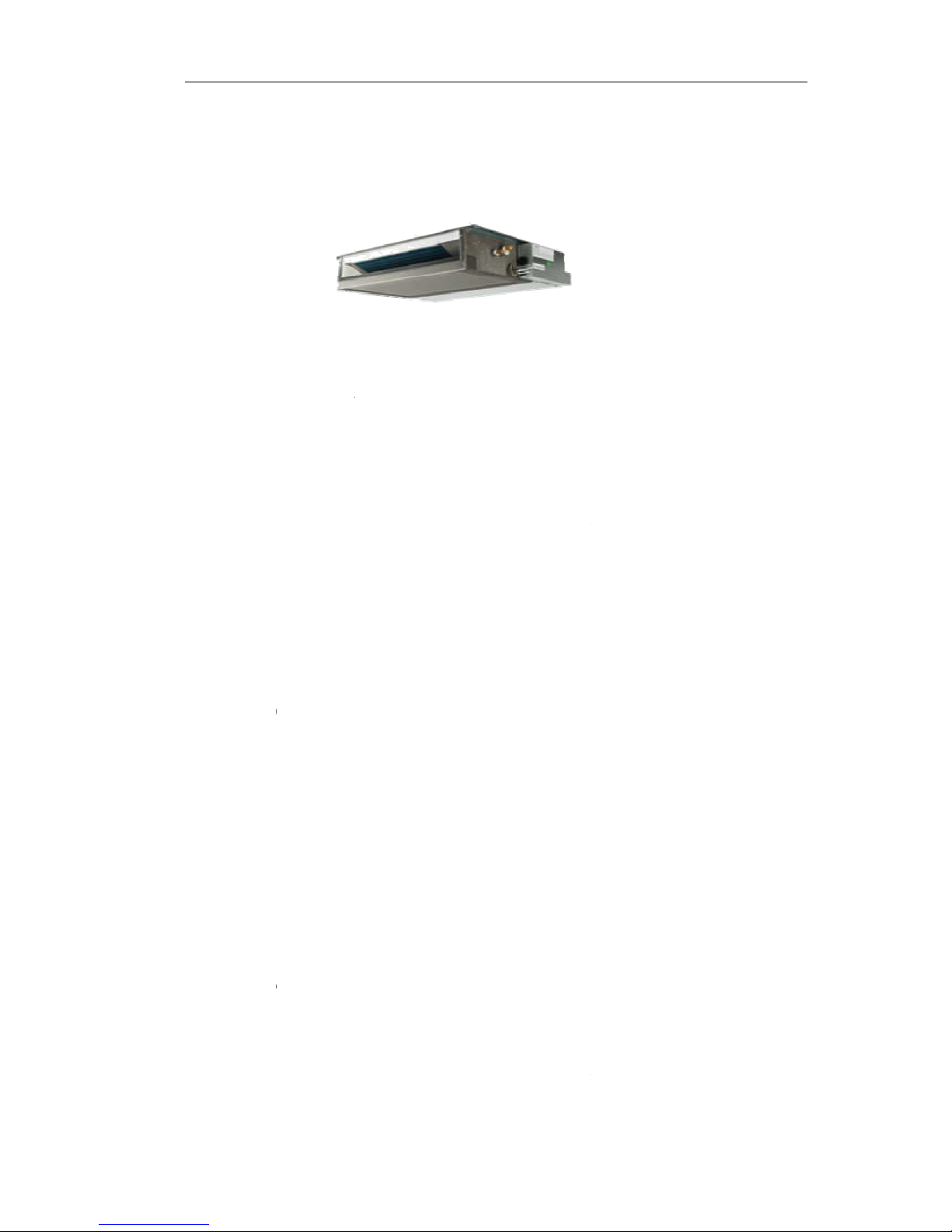
Duc
eatures
Save Ins
t
The
Optional
18k:
Pre
s
One
High Effi
c
R41
0
24-hour
T
This
24-
h
Mute Op
e
The
nois
e
Meeting
V
The
Feature
s
t Type
Ai
allation Sp
a
indoor unit
c
Static Press
optional 10
P
sure.
unit, two in
s
iency and
E
A can prot
e
imer ON a
n
Timer can
b
our period.
ration
excellent fa
n
.
arious Inst
a
back-air-inl
e
r Conditi
ce
an be instal
l
ure
a /30Pa, 2
4
tallation me
t
nvironment
ct the envir
o
d OFF
e set to aut
o
design en
a
llation Req
u
t type is us
u
oner
ed inside th
e
K 36K 50P
a
hod.
Friendly Ne
w
nment and
d
matically tu
ble the airfl
o
irements
ally to be a
d
ceiling co
n
/80Pa, 48K
/
Refrigeran
o not harm
n the unit o
n
w to be qui
e
opted acco
r
veniently.
60K: 80Pa/1
t-R410A
to the ozon
e
or off at h
a
t and smoo
t
ding to the
a
1.G
E
20Pa static
layer.
lf-hour withi
n
h with mini
m
ctual install
a
NERAL
1
a
um
tion
Page 4

1.GENERAL
2
space.
The unit is also installed with down-air-inlet type.
¾ Self Recovery of Power Break
When the power supply is recovered after break, all preset are still effective and the
air-conditioner can run according to the original setting.
¾ Fault Self-diagnose Function
When there is something wrong with the air-conditioner,the micro computer could
diagnose the faults, which can be read from the display and is convenient for
maintenance.
Page 5

C
F
e
¾¾¾
¾¾¾
assette
T
atures
Save Ins
t
The indo
o
High Effi
c
R410A c
a
24-hour
T
This Tim
e
period.
Mute Op
e
The exc
e
Self Rec
o
When th
e
air-condi
t
Fault Sel
f
When th
e
the fault
ype Air
allation Sp
a
r unit can
b
iency and
E
n protect th
imer ON a
n
r can be se
t
ration
llent fan de
s
very of Po
w
power sup
p
ioner can ru
-diagnose
F
re is somet
h
s, which ca
n
Conditio
n
ce
e installed i
n
nvironment
e environm
e
d OFF
to automat
i
ign enable t
er Break
ly is recove
n according
unction
ing wrong
w
be read fro
m
er
side the cei
l
Friendly Ne
w
nt and do n
o
cally turn th
e
he airflow to
red after br
e
to the origin
a
ith the air-c
o
the displa
y
ing conveni
e
Refrigeran
t harm to th
unit on or
o
be quiet an
d
ak, all pres
e
l setting.
nditioner, th
and is con
v
ntly.
t-R410A
e ozone lay
e
ff at half-ho
u
smooth wi
t
t are still eff
e
e micro co
m
enient for
m
1.G
E
r.
ur within a 2
4
h minimum
n
ctive and t
h
puter could
d
aintenance.
NERAL
3
-hour
oise.
e
iagnose
Page 6
1.GENERAL
4
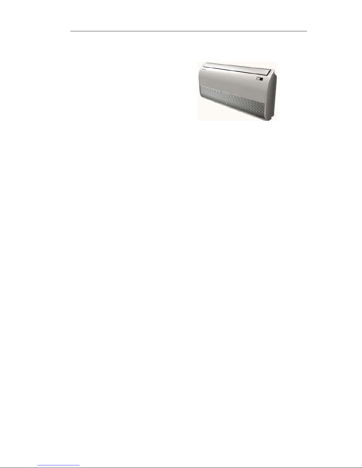
Ceiling&Floor Air Conditioner
Features
¾ Save Installation Space
The indoor unit’s thickness is only 230mm,can be installed inside the ceiling conveniently.
¾ Flexible Installation Options
According to the actual installation space,The indoor unit can be installed in the ceiling
or on the floor. One unit, Two installation method.
¾ High Efficiency and Environment Friendly
New Refrigerant-R410A
R410A can protect the environment and do not harm to the ozone layer.
¾ 24-hour Timer ON and OFF
This Timer can be set to automatically turn the unit on or off at half-hour within a 24-hour period.
¾ Mute Operation
The excellent fan design enable the airflow to be quiet and smooth with minimum noise.
¾ Various Refrigerant Pipe Connect Methods
The refrigerant pipe can be connect from 3 different directions(rear,right or top) .More methods,
more conveniently.
¾ Self Recovery of Power Break
When the power supply is recovered after break, all preset are still effective and the
Page 7

1.GENERAL
5
air-conditioner can run according to the original setting.
¾ Fault Self-diagnose Function
When there is something wrong with the air-conditioner, the micro computer could diagnose the
faults, which can be read from the display and is convenient for maintenance.
Page 8
1.GENERAL
6
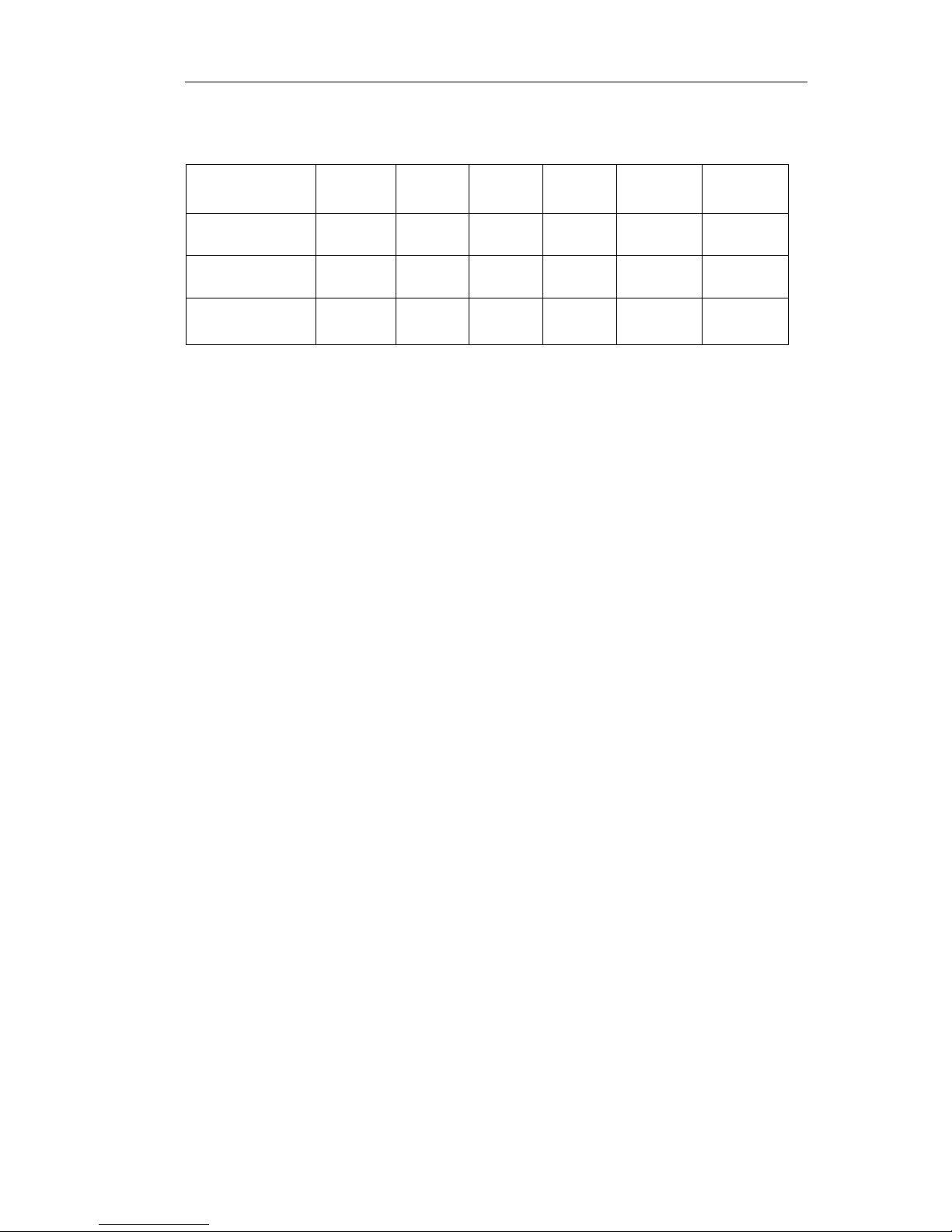
1.2 Product Lineup
Type Model 18 24 36 48 60
Duct Type AUD ● ● ● ● ●
Cassette Type AUC ● ● ● ● ●
Ceiling&Floor
Type
AUV ● ● ● ● ●
Note:18=18K btu type
Page 9
1.GENERAL
7
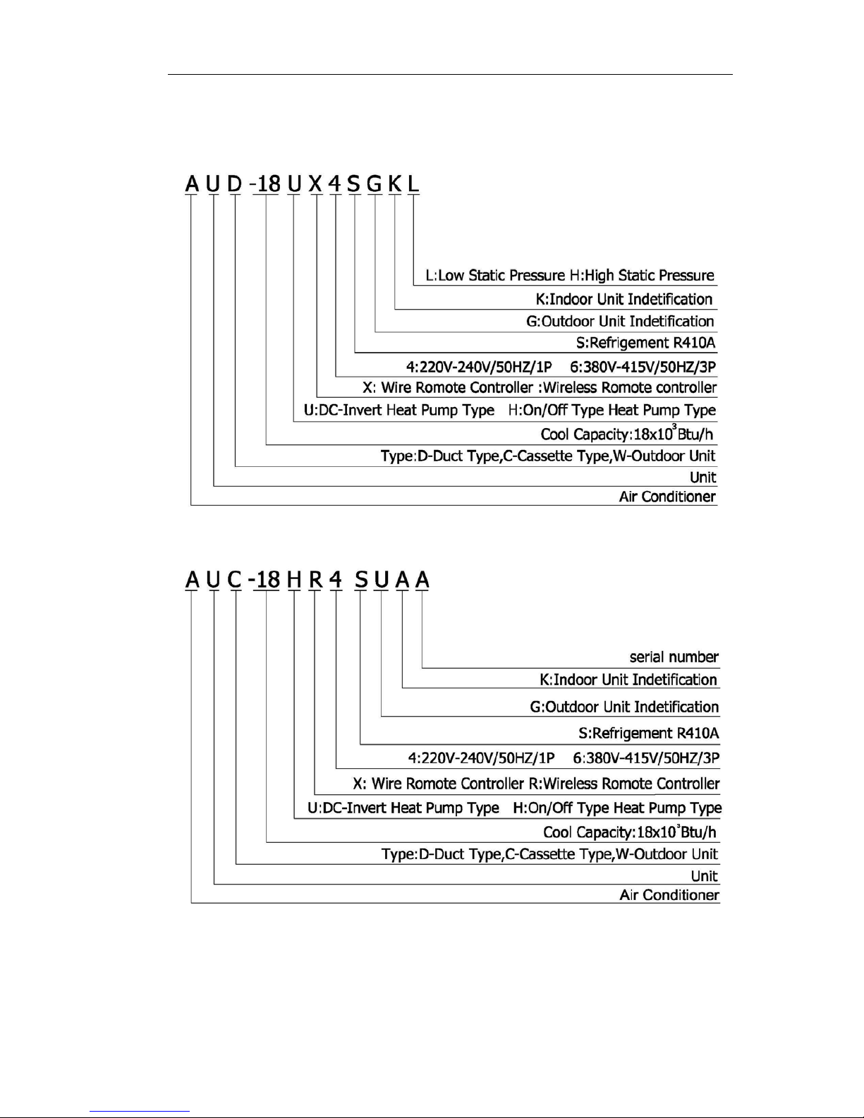
1.3 MODEL IDENTIFICATION
Page 10
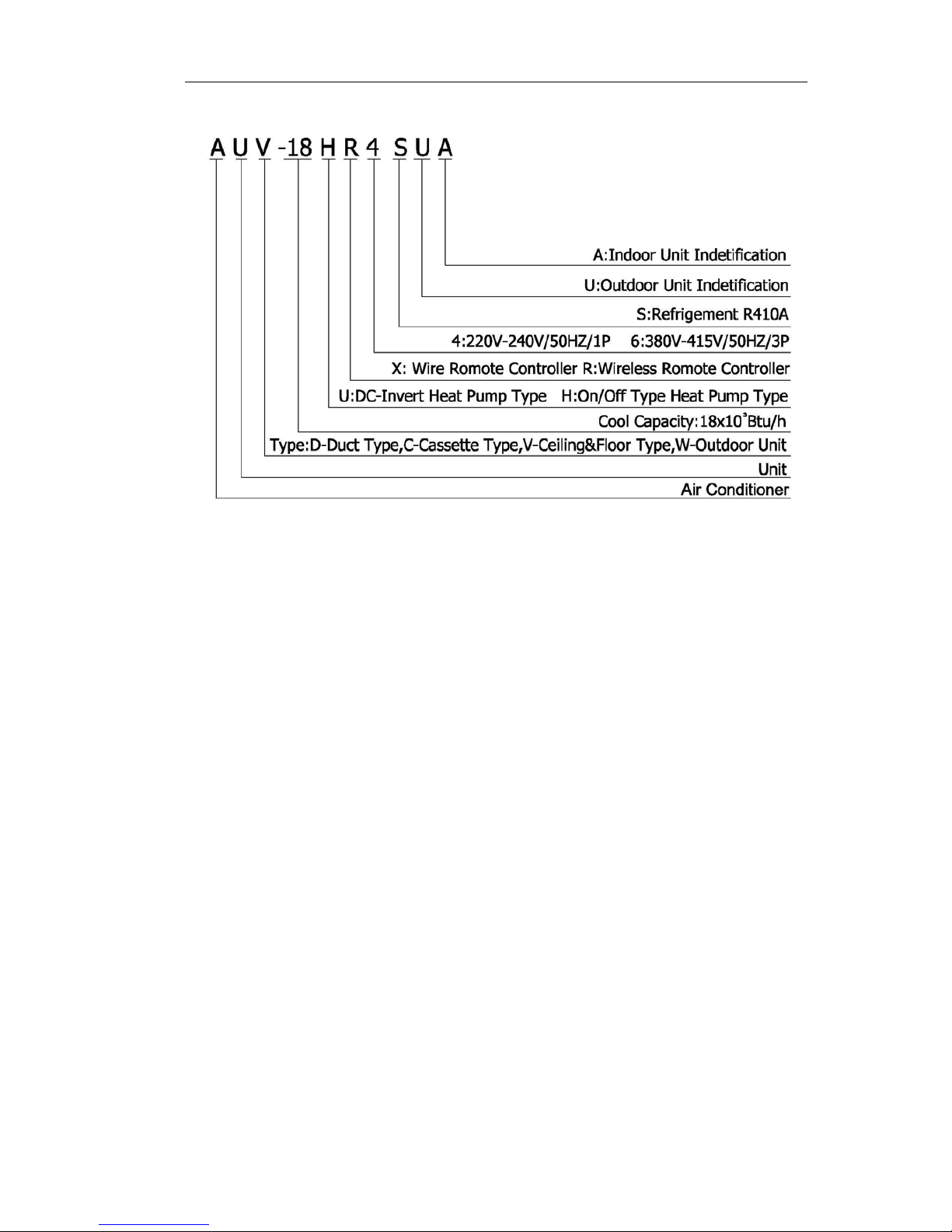
1.GENERAL
8
Page 11
1
D
M
I
O
u
M
I
O
u
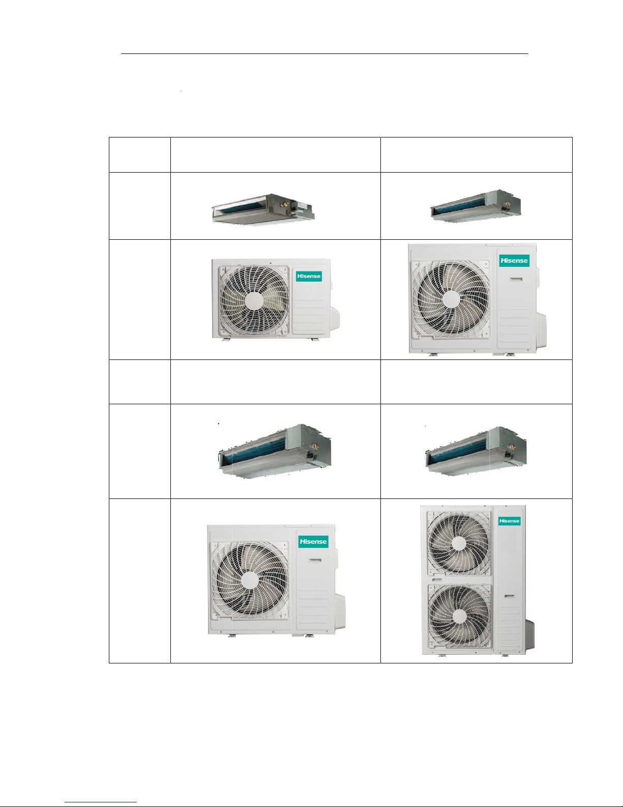
.4 Prod
u
uct Typ
odel
ndoor
tdoor
odel
ndoor
tdoor
ct Pic
t
e
ure
AUD-18HX
4
AUD-36HX
6
SUNL
SAHH
1.G
E
AUD-24HX4
S
AUD-48HX6
S
AUD-60HX6
S
NERAL
9
ZLH
PHH
PHH
Page 12
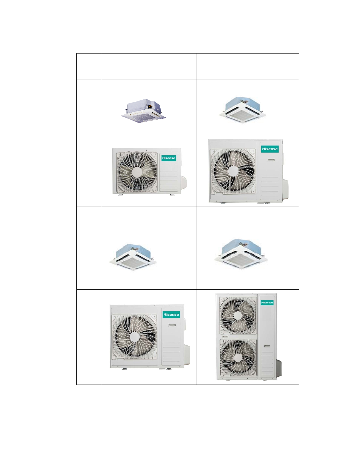
C
a
ssette T
Model
Indoor
Outdoor
Model
Indoor
Outdoor
ype
A
UAU
C-18HR4SU
A
C-36HR6SA
G
A
A
AUC-24HR
4
AUC-48HR
6
AUC-60HR
6
1.G
E
SZGA
SPHA
SPHA
NERAL
10
Page 13
1.GENERAL
11
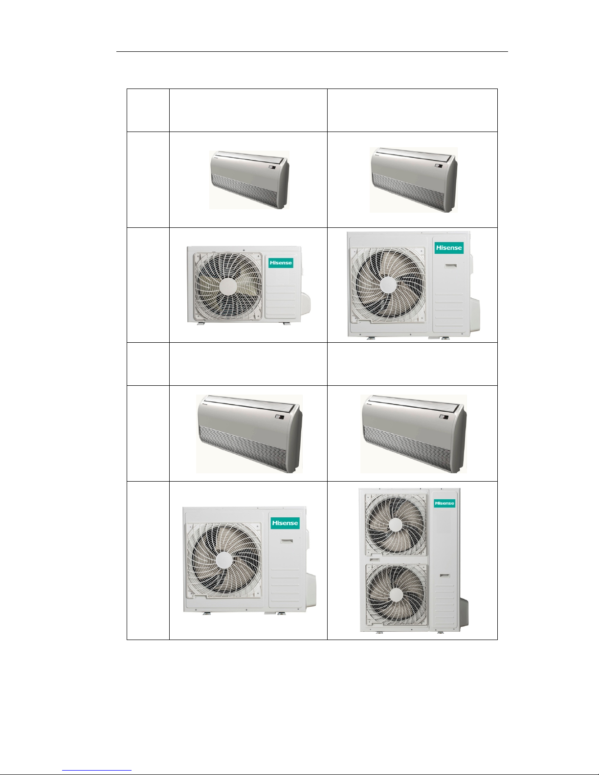
Ceiling&Floor Type
Model AUV-18HR4SUA AUV-24HR4SZA
Indoor
Outdoor
Model AUV-36HR6SAB
AUV-48HR6SPC
AUV-60HR6SPC
Indoor
Outdoor
Page 14
2.SPECIFICATIONS
12
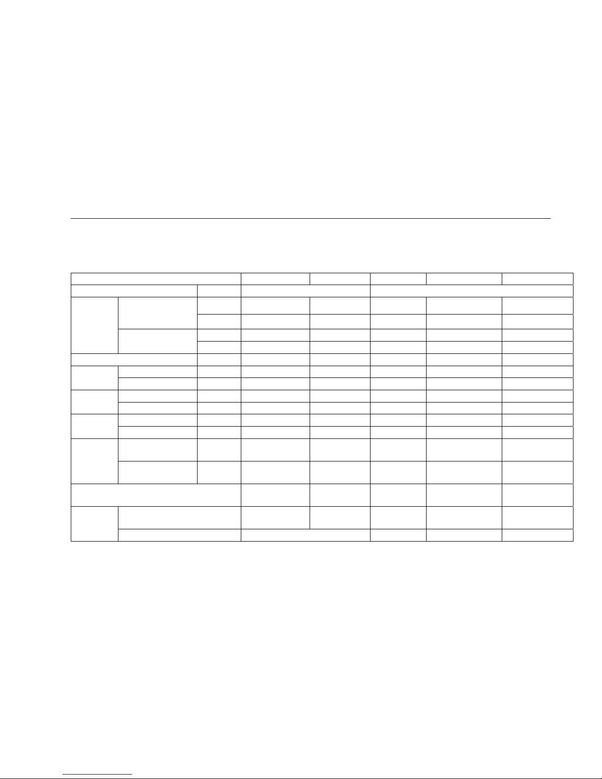
2.Specifications
2.1DuctType
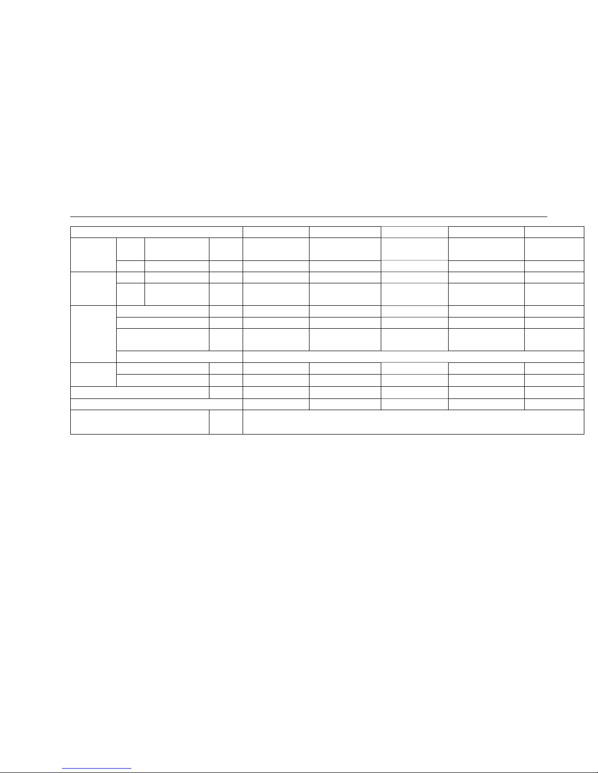
Model AUD-18HX4SUNL AUD-24HX4SZLH AUD-36HX6SAHH AUD-48HX6SPHH AUD-60HX6SPHH
Power supply Ph-V-Hz 1N,220V~240V/50Hz 3N~,380V-415V/50Hz
Capacity
Cooling
kW 5 7.4
10 14 16
Btu/h 17,000 25,300 34,100 47,800 54,600
Heating
kW
5.5 7.9 11 15 17.5
Btu/h 18,800 26,900 37,500 51,200 59,700
Dehumidification L/h 1.3 1.3 2.3 3.5 3.5
Rated input
Cooling kW
1.55 2.45 3.55 4.651 5.694
Heating kW 1.6 2.19 3.65 4.532 5.814
Rated Current
Cooling A
7.09 11.5 6.0 8.8 10.0
Heating A 7.32 11 6.5 8.6 10.3
Max. input
Cooling kW
2.311 3.2 5.5 6.5 7.932
Heating kW 2.311 3.2 5.5 6.4 8.234
Max.Current
Cooling A
10.53
15.5 9.0 12.1 15.6
Heating A
10.53
15.5 9.0 11.6 16.6
EER/COP 2.81/3.06 3.02/3.61
3.23/3.44
3.01/3.31 2.81/3.01
Compressor
Model
PA190M2CS-4KTL
PA290G2CS-4MUL
1
C-SBN303H8D C-SBN737H8D C-SBN453H8D
Type Rotary scroll scroll scroll
Page 15
2.SPECIFICATIONS
13
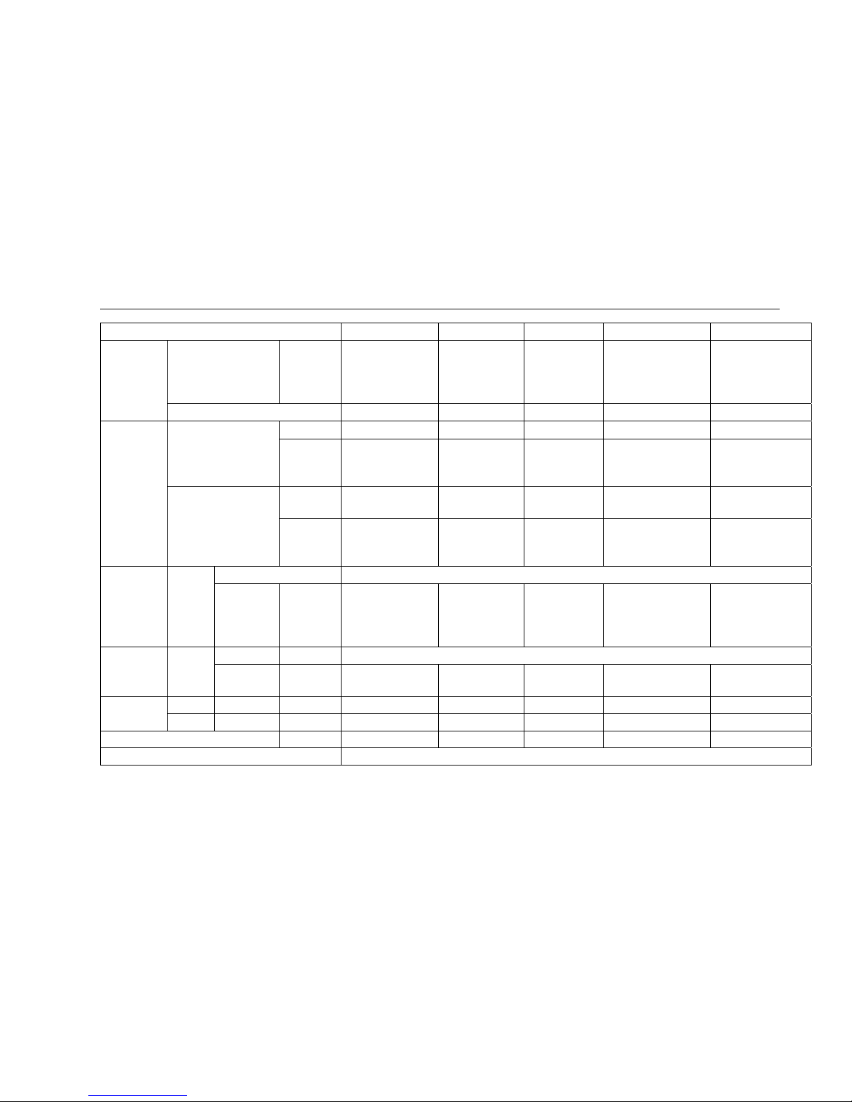
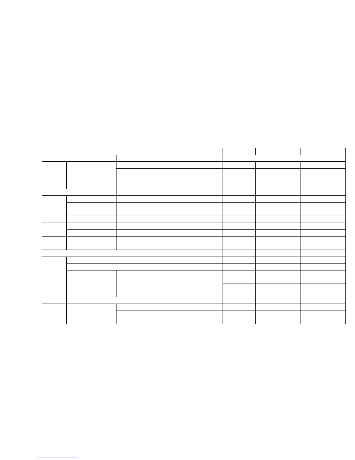
Model AUD-18HX4SUNL AUD-24HX4SZLH AUD-36HX6SAHH AUD-48HX6SPHH AUD-60HX6SPHH
Winding resistance(20℃) Ω M:2.1,A:2.81 M:1.37,A:1.7
U-V:
2.806;U-W :2.806;
V-W: 2.651 (at
25℃)
U-V: 2433;U-W :2433;
V-W: 2.304(at 25℃)
U-V: 2433;U-W :2433;
V-W: 2.304(at 25℃)
Brand GMCC GMCC SANYO SANYO SANYO
Fan motor
Indoor
Model
YSK95-45-4-B Y6S419C56 Y7S423B814 Y7S423C237 Y7S423C237
Winding
resistance
(at20℃)
M:138;A:178 M:70.1;A:75.5 M:52.5;A:29.5 M:17.89;A:27.2 M:17.89;A:27.2
Outdoor
Model
YDK29-6I-25 YDK70-6H-3 YDK95-6-9043
YDK65-6-9024
YDK65-6-9061
YDK65-6-9024
YDK65-6-9061
Winding
resistance
(at20℃)
M:231.5;A:168 M:78;A:80 M:59.1;A:85.8
M:83;A1:23.4A2:14A1:63.5 M:83;A1:23.4A2:14A1:6
3.5
Fan Indoor
type
centrifugal fan
Speed
Hi/Med/Low
r.p.m
1070/1130/1280(10Pa)
1220/1270/1370(30Pa)
860/990/1070(50Pa)
50Pa:
810/835/880
80Pa:
900/925/965
830/900/1000(80Pa) 830/900/1000(80Pa)
Fan speed Outdoor
type r.p.m
tube-axial
Speed
Hi/Med/Low
r.p.m
890/-/950 560/780/840 540 / 640 / 800 500 / 600 / 700 500 / 600 / 700
Air circulation
Indoor Hi/Med/Low m³/h
780 1100 1800 2000 2000
Outdoor Hi/Med/Low m³/h -- -- -- -- --
Static Pressure(*Default Setting) Pa 10*/30 50*/80 50*/80 80*/120 80*/120
Operating control Wire Remote control
Page 16
2.SPECIFICATIONS
14
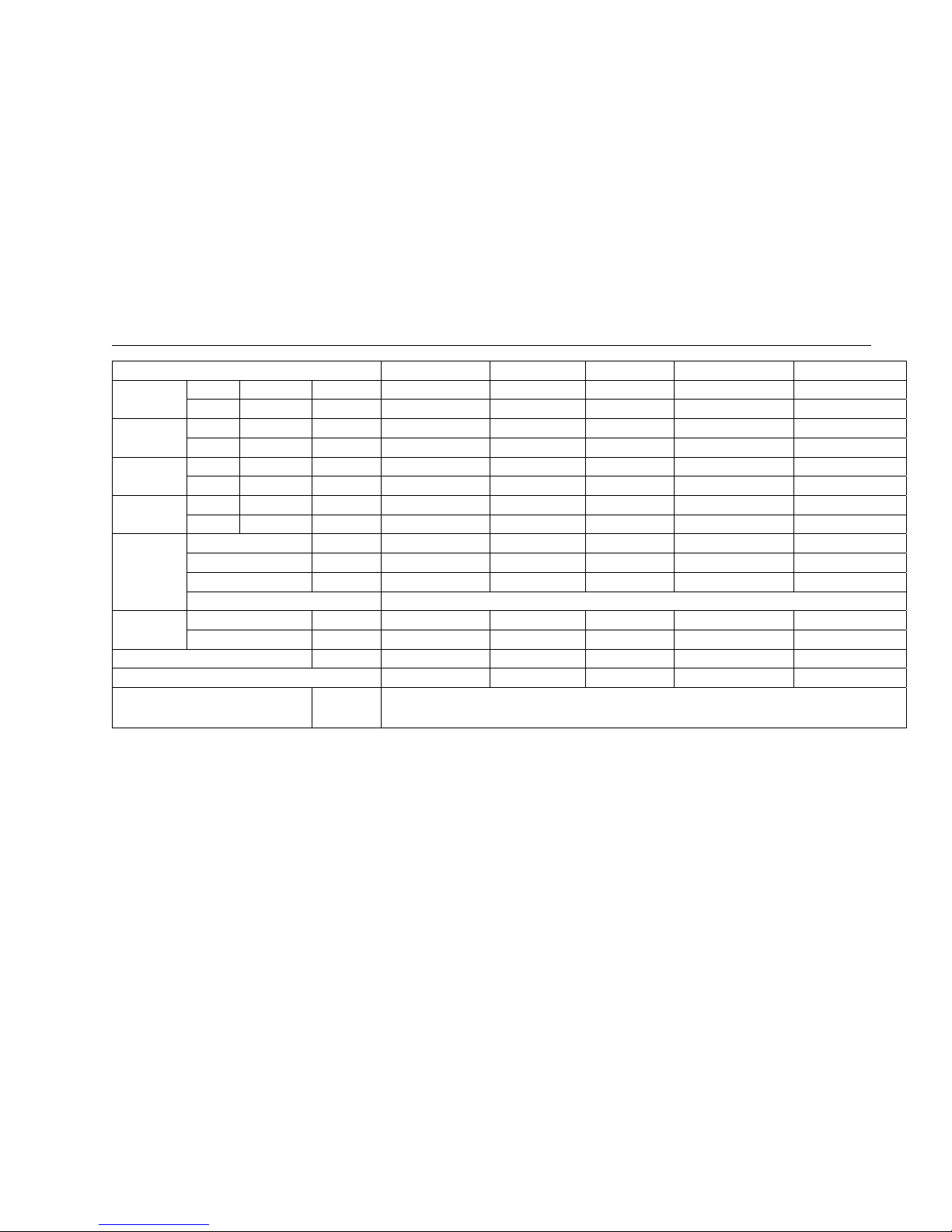
Model AUD-18HX4SUNL AUD-24HX4SZLH AUD-36HX6SAHH AUD-48HX6SPHH AUD-60HX6SPHH
Dimensions
Indoor L×W×H mm
900×447×190 900×720×270 1300×800×350 1300×800×350 1300×800×350
Outdoor L×W×H mm 800×260×550 900×300×640 950×340×840 950×340×1386 950×340×1386
Packing
Indoor L×W×H mm
1070×580×270 1170×870×340 1550×940×410 1550×940×410 1550×940×410
Outdoor L×W×H mm 930×360×620 1050×400×700 1100×460×920 1110×460×1530 1110×460×1530
Weight
Indoor Net/Gross kg
20/24 32/37 50/58 54/62 50/58
Outdoor Net/Gross kg 37/42 54/60 71/81 114/124 109 /119
Noise lever
Indoor Hi/Med/Low Db
--/43 43/49 --/50 49/53 49/53
Outdoor Hi/Med/Low Db --/55 53/58 --/60 --/62 --/62
Refrigerant
piping
Gas/Liquid mm
12.7/6.35 15.88/9.52 15.88/9.52 19.05/9.52 19.05/9.52
Max. refrigerant pipe length m 15 20 30 50 50
Max. difference in level m 7.5 10 15 20(outdoor blow:15) 20(outdoor blow:15)
Connection method Flare
Connection
wiring
Power wiring mm
2
3 core x1.5 3 core x2.5 5 core x1.5 5 core x2.5 5 core x2.5
Signal wiring mm2 5 core x1.5 4core x0.75 4core x0.75 4core x0.75 4core x0.75
Refrigerant charge(R410a) kg 1.2 1.65 2.3 3.1 3.3
Throttle Type Capillary Capillary Capillary Capillary Capillary
Ambient temp
℃
Cooling 15~43
Heating -10~24
Page 17
2.SPECIFICATIONS
15
2.2CassetteType
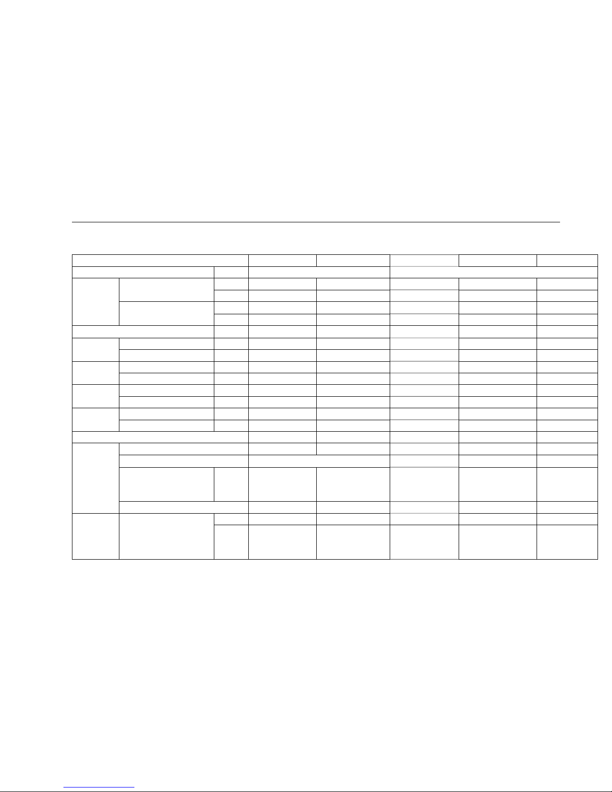
Model AUC-18HR4SUAA AUC-24HR4SZGA AUC-36HR6SAGA AUC-48HR6SPHA AUC-60HR6SPHA
Power supply Ph-V-Hz
1N,220V~240V/50Hz 3N~,380V~418V/50Hz
Capacity
Cooling
kW
5 7.45 10 14 16
Btu/h
17,000 25,400 34,100 47,800 54,600
Heating
kW
5.5 7.5 11 14.8 17.5
Btu/h
18,800 25,600 37,500 50,500 59,700
Dehumidification L/h
1.8 2 2.3 4.5 4.5
Rated input
Cooling kW
1.55 2.32 3.6 4.844 5.694
Heating kW
1.55 2.08 3.7 4.853 5.814
Rated Current
Cooling A
7.09 10.8 6.0 9.3 10
Heating A
7.09 10 6.5 9.3 10.3
Max. input
Cooling kW
2.3 3.2 5.5 11.8 7.932
Heating kW
2.3 3.2 5.5 11.2 8.234
Max.Current
Cooling A
10.53 15.5 9 6.2 15.6
Heating A
10.53 15.5 9 6.135 16.6
EER/COP
3.23/3.55 3.21/3.61 2.81/3.01 2.89/3.05 2.81/3.01
Compressor
Model
PA190M2CS-4KTL PA290G2CS-4MUL1 C-SBN303H8D C-SBN737H8D C-SBN453H8D
Type
Rotary scroll scroll scroll
Winding resistance Ω
M:2.1,A:2.81 M:1.37,A:1.7
U-V: 2.806;U-W :2.806;
V-W: 2.651 (at 25℃)
U-V: 2433;U-W :2433;
V-W: 2.304(at 25℃)
U-V:
2433;U-W :2433;
V-W: 2.304(at 25℃)
Brand
GMCC GMCC SANYO SANYO SANYO
Fan motor Indoor
Model
YDK95-28-4-B(HS21) YDK30-8-3 YDK75-8-2 YDK80-8-2 YDK80-8-2
Winding
resistanc
e
M:240;A:245,60,33,143 M:209.4;A:245,60,33,143 M:75;A:97.5 M:79.7;A:59.4,20.2,108
M:79.7;A:59.4,20.2,
108
Page 18

2.SPECIFICATIONS
16
Model AUC-18HR4SUAA AUC-24HR4SZGA AUC-36HR6SAGA AUC-48HR6SPHA AUC-60HR6SPHA
(at20℃)
Outdoor
Model
YDK29-6I-25 YDK70-6H-3 YDK95-6-9043
YDK65-6-9024
YDK65-6-9061
YDK65-6-9024
YDK65-6-9061
Winding
resistanc
e
(at20℃)
M:231.5;A:168 M:78;A:36.2,51.5,109.2 M:59.1;A:85.8 M:83;A1:23.4A2:14A1:63.5
M:83;A1:23.4A2:14
A1:63.5
Fan Indoor
type
centrifugal fan
Speed Hi/Med/Low r.p.m
720/840/980 270/390/450 480/530/610 450/550/640 450/550/640
Fan speed
Outdoo
r
type r.p.m
tube-axial
Speed Hi/Med/Low r.p.m
890/920/950 560/780/840 540 / 640 / 800 500 / 600 / 700 500 / 600 / 700
Air
circulation
Indoor Hi/Med/Low m³/h
800 1100 1800 2000 2000
Outdoo
r
Hi/Med/Low m³/h
-- -- -- -- --
Static Pressure(*Default Setting) Pa
0 0 0 0 0
Operating control
Wireless Remote control(J1-05)
Dimensions
Indoor L×W×H mm
650×570×270 840×840×248 840×840×248 840×840×298 840×840×298
Outdoo
r
L×W×H mm
800×260×550 900×300×640 950×340×840 950×340×1386 950×340×1386
Panel L×W×H mm
650×650×30 950×950×37 950×950×37 950×950×37 950×950×37
Packing
Indoor L×W×H mm
770×750×370 930×930×290 930×930×290 930×930×340 930×930×340
Outdoo
r
L×W×H mm
940×360×640 1080×420×720 1110×460×980 1110×460×1530 1110×460×1530
Panel L×W×H mm
650×650×30 1010×990×95 1010×990×115 1010×990×115 1010×990×115
Weight Indoor Net/Gross kg
20/27 36/43 30/36 33/39 33/39
Page 19
2.SPECIFICATIONS
17
Model AUC-18HR4SUAA AUC-24HR4SZGA AUC-36HR6SAGA AUC-48HR6SPHA AUC-60HR6SPHA
Outdoo
r
Net/Gross kg
37/42 54/60 71/81 114/124 114/124
Panel Net/Gross kg
2.4/5 6/7.5 6/7.5 6/7.5 6/7.5
Noise lever
Indoor Hi/Med/Low Db
35/46 36/43 --/50 46/52 46/52
Outdoo
r
Hi/Med/Low Db
--/55 53/58 --/60 --/62 --/62
Refrigerant
piping
Gas/Liquid mm
12.7/6.35 15.88/9.52 15.88/9.52 19.05/9.52 19.05/9.52
Max. refrigerant pipe length m
15 20 30 50 50
Max. difference in level m
7.5 10 15
20(outdoor blow:15)
20(outdoor blow:
15)
Connection method
Flare
Connection
wiring
Power wiring mm
2
3 core x1.5 3 core x2.5 5 core x1.5 5 core x2.5 5 core x2.5
Signal wiring mm2
5 core x1.5 4core x0.75 4core x0.75 4core x0.75 4core x0.75
Refrigerant charge(R410a) kg
1.2 1.65 2.3 3.1 3.3
Throttle Type
Capillary Capillary Capillary Capillary Capillary
Ambient temp
℃
Cooling 15~43
Heating -7~24
Page 20
2.SPECIFICATIONS
18
2.3Ceiling&Floortype
Model
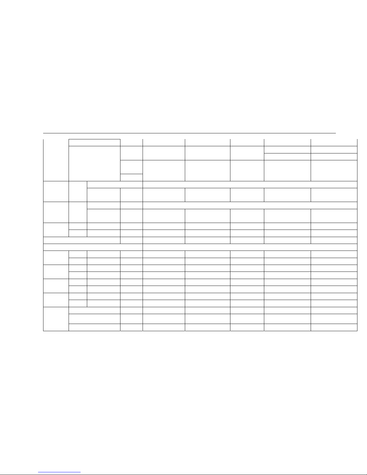
AUV-18HR4SUA AUV-24HR4SZA AUV-36HR6SAB AUV-48HR6SPC AUV-60HR6SPC
Power supply Ph-V-Hz
1N,220V~240V/50Hz 3N~,380V~418V/50Hz
Capacity
Cooling
kW
5 7.7 10.2 14 16
Btu/h
17,000 26,300 34,800 47,800 54,600
Heating
kW
5.5 7.9 12 16 18
Btu/h
18,800 27,000 40,900 54,600 61,400
Dehumidification L/h
1.8 2 2.3 4.5 4.5
Rated input
Cooling kW
1.5 2.4 3.625 4.651 5.694
Heating kW
1.595 2.19 3.725 4.523 5.814
Rated
Current
Cooling A
7.1 11.2 6.7 8.8 10
Heating A
7.3 11 7 8.6 10.3
Max. input
Cooling kW
2.3 3.2 5.5 6.479 7.932
Heating kW
2.3 3.2 5.5 6.418 8.234
Max.Current
Cooling A
10.5 15.5 9 12.1 15.6
Heating A
10.5 15.5 9 11.6 16.6
EER/COP
3.23/3.44 3.21/3.61 2.81/3.22 3.01/3.53 2.81/3.1
Compressor
Model
PA190M2CS-4KTL PA290G2CS-4MUL1 C-SBN303H8D C-SBN737H8D C-SBN453H8D
Type
Rotary scroll scroll scroll
Winding resistance Ω
M:2.1,A:2.81 M:1.37,A:1.7
U-V:
2.806;U-W :2.806;
U-V: 2433;U-W :2433; U-V: 2433;U-W :2433;
V-W: 2.651 (at
25℃)
V-W: 2.304(at 25℃) V-W: 2.304(at 25℃)
Brand
GMCC GMCC SANYO SANYO SANYO
Fan motor Indoor
Model
YSK110-22-4-A YSK110-100-4-A Y7S423B212 Y7S423C032 Y7S423C032
Winding
resistance
M:187 A1:37.5 A2:
27.8 A3: 146
M:55 A1:23.2 A2: 10.9
A3: 18.3
M:41.49 A:35.21
黑蓝: 13.25 蓝
M:42.69 A:36.41 黑蓝:
9.19 蓝黄:9.09
M:42.69 A:36.41 黑蓝:
9.19 蓝黄:9.09
Page 21
2.SPECIFICATIONS
19
(at20℃)
黄:12.39
Outdoor
Model
YDK29-6I-25 YDK70-6H-3 YDK95-6-9043
YDK65-6-9024 YDK65-6-9024
YDK65-6-9061 YDK65-6-9061
Winding
resistance
M:231.5;A:168 M:78;A:36.2,51.5,109.2 M:59.1;A:85.8 M:83;A1:23.4A2:14A1:63.5 M:83;A1:23.4A2:14A1:63.5
(at20℃)
Fan Indoor
type
centrifugal fan
Speed
Hi/Med/Low
r.p.m
630/720/800 830/1000/1180 1090/1210/1350 1060/1145/1250 1060/1145/1250
Fan speed Outdoor
type r.p.m
tube-axial
Speed
Hi/Med/Low
r.p.m
890/920/950 560/780/840 540 / 640 / 800 500 / 600 / 700 500 / 600 / 700
Air
circulation
Indoor Hi/Med/Low m³/h
800 1100 1600 2000 2000
Outdoor Hi/Med/Low m³/h
-- -- -- -- --
Static Pressure(*Default Setting) Pa
0 0 0 0 0
Operating control
Wireless Remote control(J1-05)
Dimensions
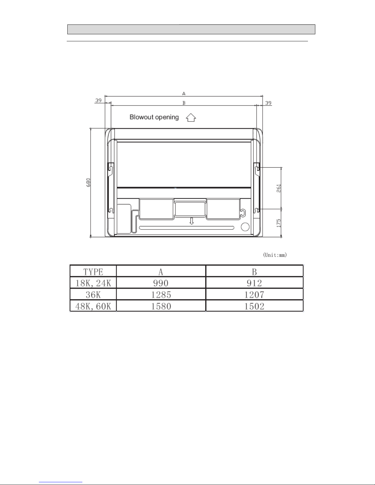
Indoor L×W×H mm
990×680×230 990×680×230 1290×680×230 1580×680×230 1580×680×230
Outdoor L×W×H mm
800×260×550 900×300×640 950×340×840 950×340×1386 950×340×1386
Packing
Indoor L×W×H mm
1100×820×350 1100×820×350 1400×820×350 1690×820×350 1690×820×350
Outdoor L×W×H mm
940×360×640 1080×420×720 1110×460×980 1110×460×1530 1110×460×1530
Weight
Indoor Net/Gross kg
27/33 30/35 37/44 44/52 44/52
Outdoor Net/Gross kg
37/42 54/60 71/81 114/124 114/124
Noise lever
Indoor Hi/Med/Low Db
--/41 45/52 48/53 49/52 49/52
Outdoor Hi/Med/Low Db
--/55 53/58 --/60 --/62 --/62
Refrigerant
piping
Gas/Liquid mm
12.7/6.35 15.88/9.52 15.88/9.52 19.05/9.52 19.05/9.52
Max. refrigerant pipe length m
15 20 30 50 50
Max. difference in level m
7.5 10 15
20(outdoor blow:15) 20(outdoor blow:15)
Page 22
2.SPECIFICATIONS
20
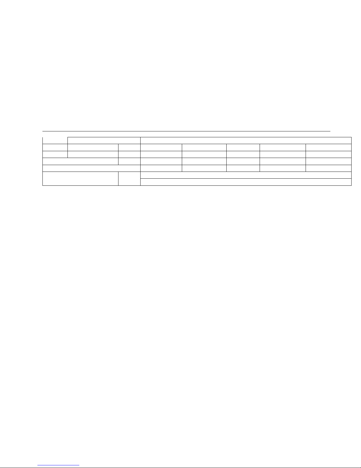
Connection method
Flare
Connection Power wiring mm2
3 core x1.5 3 core x2.5 5 core x1.5 5 core x2.5 5 core x2.5
wiring Signal wiring mm2
5 core x1.5 4core x0.75 4core x0.75 4core x0.75 4core x0.75
Refrigerant charge(R410a) kg
1.2 1.65 2.3 3.1 3.3
Throttle Type
Capillary Capillary Capillary Capillary Capillary
Ambient temp
℃
Cooling 15~43
Heating -7~24
Page 23
33.. OOUUTTLLIINNEESS AANNDD DDIIMMEENNSSIIOO
21
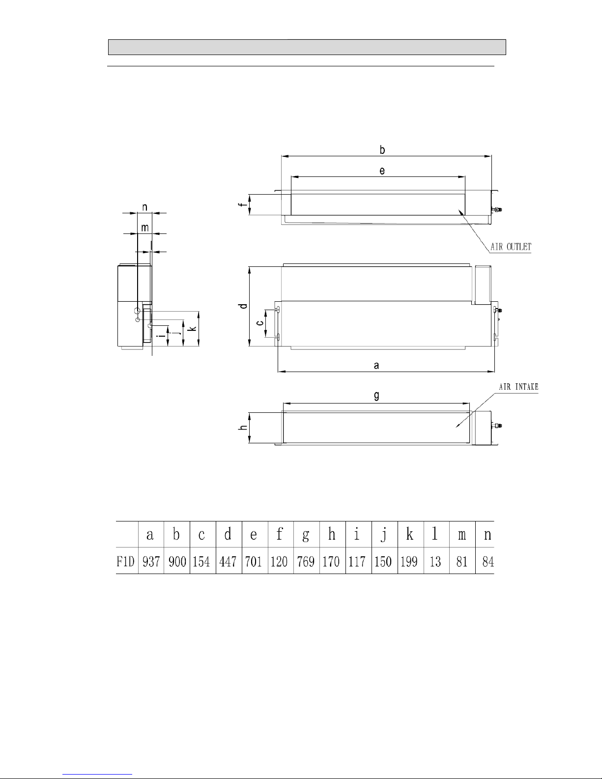
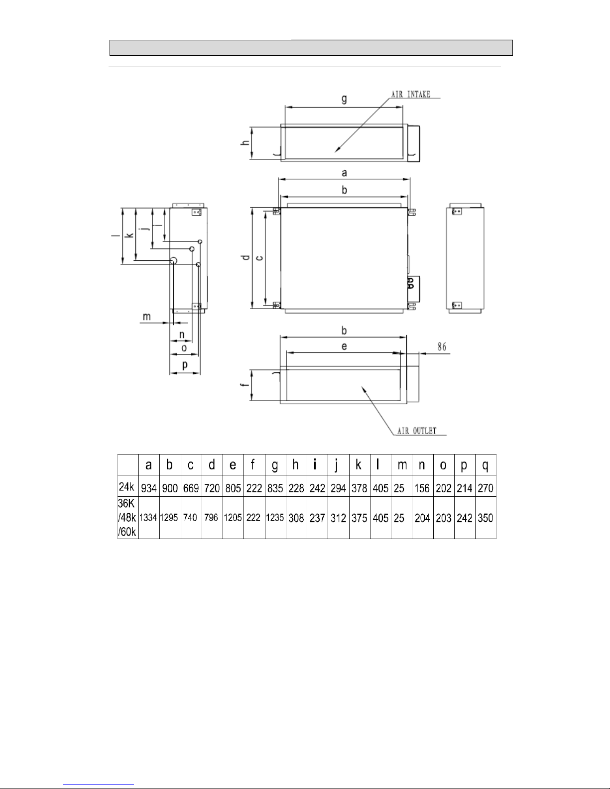
3.Duct Type
3.1 INDOOR
Page 24
33.. OOUUTTLLIINNEESS AANNDD DDIIMMEENNSSIIOO
22
Page 25
33.. OOUUTTLLIINNEESS AANNDD DDIIMMEENNSSIIOO
23
2.Cassette Type
(
MODEL: AUC-18HR4SUAA)
Page 26
33.. OOUUTTLLIINNEESS AANNDD DDIIMMEENNSSIIOO
24
(
MODEL: AUC-24HR4SZGA
、
AUC-36HR6SAGA
、
AUC-48HR6SPHA、AUC-60HR6SPHA)
Page 27
33.. OOUUTTLLIINNEESS AANNDD DDIIMMEENNSSIIOO
25
3.Ceiling&Floor Type
Page 28
33.. OOUUTTLLIINNEESS AANNDD DDIIMMEENNSSIIOO
26
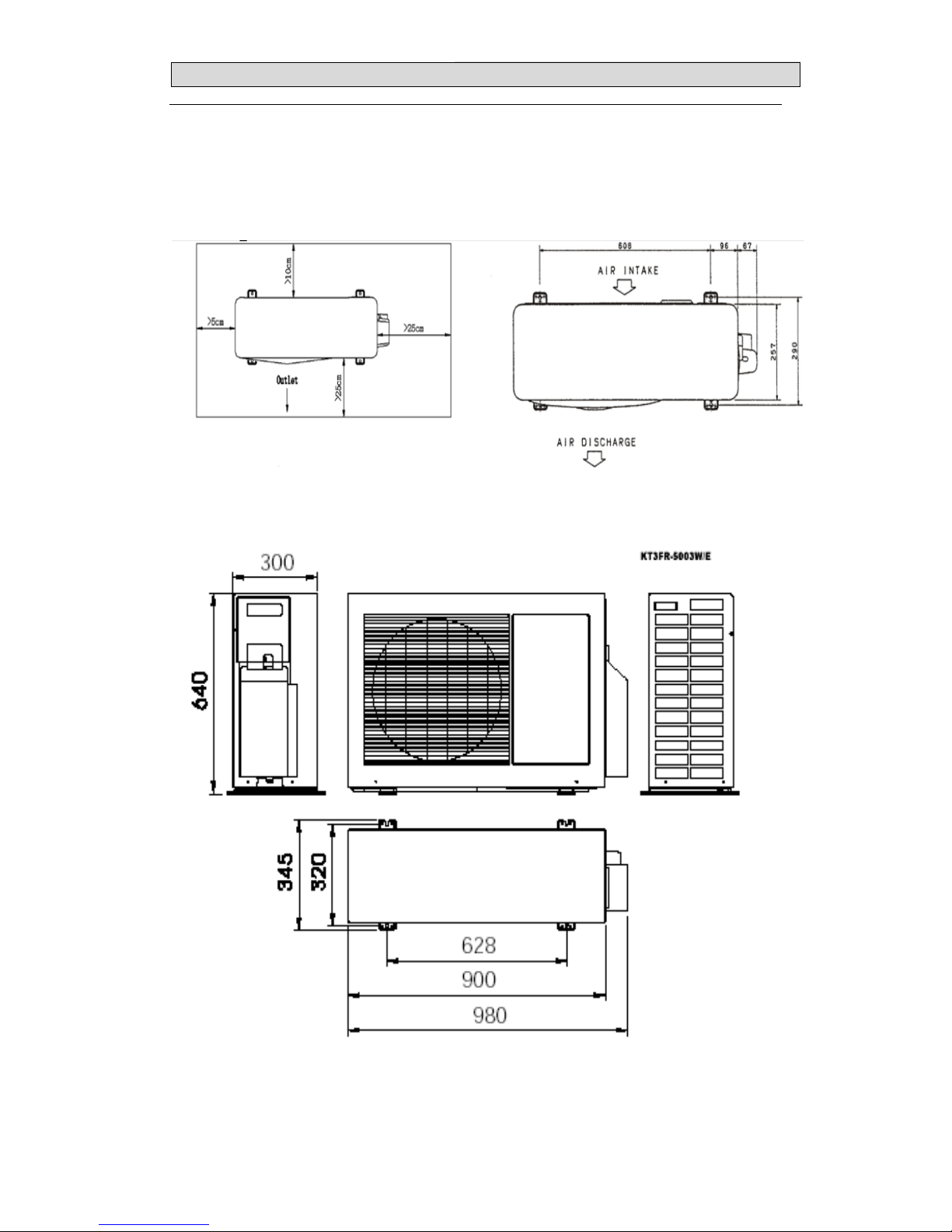
3-2.OUTDOOR
(
MODEL: AUW-18H4SU)
MODEL: AUW-24H4SZ
Page 29

33.. OOUUTTLLIINNEESS AANNDD DDIIMMEENNSSIIOO
27
(
MODEL: AUW-36H6SA)
Page 30
33.. OOUUTTLLIINNEESS AANNDD DDIIMMEENNSSIIOO
28
Page 31

33.. OOUUTTLLIINNEESS AANNDD DDIIMMEENNSSIIOO
29
(
MODEL: AUW-48H6SP、AUW-60H6SP)
Page 32

4.REFRIGERANT FLOW DIAGRAM
30
4.Piping Diagrams& ELECTRIC Diagrams
4.1 Piping Diagrams
18K
24K
Page 33

4.REFRIGERANT FLOW DIAGRAM
31
36K
48K、60k
Page 34

4.REFRIGERANT FLOW DIAGRAM
33
4.2ELECTRIC Diagrams
18K
24K
36K/48K/60K
Page 35

4.REFRIGERANT FLOW DIAGRAM
32
MAX.Refrigerantpipelengthandheightdifference:
*Doyourbesttoreducethepipelength.Longpipemaycausecapacityoftheindoorunitincline.
Outdoorunitprecharged
Total refrigerantpipelength
0m~5m
5m~60m
AUW-18H4SU
1200g 0g
Xg=15g/m × (Totalpipelength(m)‐5)
AUW-24H4SZ
1650g 0g
Xg=35g/m × (Totalpipelength(m)‐5)
AUW-36H6SA
2300g 0g
AUW-48H6SP
3100g 0g
AUW-60H6SP
3300g 0g
Page 36

4.REFRIGERANT FLOW DIAGRAM
33
4.2ELECTRIC Diagrams
18K
24K
36K/48K/60K
Page 37

4.REFRIGERANT FLOW DIAGRAM
34
Recommend Wire Size
Model POWER SUPPLY
Power Source
Cable Size
(mm2)
Transmitting
Cable Size
(mm2)
18K
220~240V,50Hz
3×1.5 5×1.5
24K 3×2.5 4×0.75
36K
380~418V,3N~,50Hz
5×1.5
4×0.75
48K/60K 5×2.5
● Use an ELB (Electric Leakage Breaker). If not used, it will cause an electric shock or a
fire.
● Do not operate the system until all the check points have been cleared.
(A) Check to ensure that the insulution resistance is more than 1 megohm, by measuring
the
resistance between ground and the terminal of the electrical parts. If not, do not operate
the system until the electrical leakage is found and repaired.
(B) Check to ensure that the stop valves of the outdoor unit are fully opened and then start
the system.
● Pay attention to the following items while the system is running.
(A) Do not touch any of the parts by hand at the discharge gas side, since the compressor
chamber and the pipes at the discharge side are heated higher than 90 .℃
(B) DO NOT PUSH THE BUTTON OF THE MAGNETIC SWITCH(ES). It will cause a
serious Accident.
NOTES:
1) Follow local codes and regulations when selecting field wires.
2) The wire sizes marked in the table are selected at the maxim current of the
unit according to the European Standard ,En60 335-1. Use the wires which are
not lighter than the ordinary tough rubber sheathed flexible cord (code
Page 38

4.REFRIGERANT FLOW DIAGRAM
35
designation H05RN-F) or ordinary polychloroprene sheathed flexible
cord (code designation H05RN-F) .
3) Use a shielded cable for the transmitting circuit and connect it to ground .
4) In the case that power cables are connected in series, add each unit
maximum current and select wires below.
* in the case that current exceeds 63A, do not connect cables in series.
Page 39

4.REFRIGERANT FLOW DIAGRAM
34
Recommend Wire Size
Model POWER SUPPLY
Power Source
Cable Size
(mm2)
Transmitting
Cable Size
(mm2)
18K
220~240V,50Hz
3×1.5 5×1.5
24K 3×2.5 4×0.75
36K
380~418V,3N~,50Hz
5×1.5
4×0.75
48K/60K 5×2.5
● Use an ELB (Electric Leakage Breaker). If not used, it will cause an electric shock or a
fire.
● Do not operate the system until all the check points have been cleared.
(A) Check to ensure that the insulution resistance is more than 1 megohm, by measuring
the
resistance between ground and the terminal of the electrical parts. If not, do not operate
the system until the electrical leakage is found and repaired.
(B) Check to ensure that the stop valves of the outdoor unit are fully opened and then start
the system.
● Pay attention to the following items while the system is running.
(A) Do not touch any of the parts by hand at the discharge gas side, since the compressor
chamber and the pipes at the discharge side are heated higher than 90 .℃
(B) DO NOT PUSH THE BUTTON OF THE MAGNETIC SWITCH(ES). It will cause a
serious Accident.
NOTES:
1) Follow local codes and regulations when selecting field wires.
2) The wire sizes marked in the table are selected at the maxim current of the
unit according to the European Standard ,En60 335-1. Use the wires which are
not lighter than the ordinary tough rubber sheathed flexible cord (code
Page 40

4.REFRIGERANT FLOW DIAGRAM
35
designation H05RN-F) or ordinary polychloroprene sheathed flexible
cord (code designation H05RN-F) .
3) Use a shielded cable for the transmitting circuit and connect it to ground .
4) In the case that power cables are connected in series, add each unit
maximum current and select wires below.
* in the case that current exceeds 63A, do not connect cables in series.
Page 41

55.. EELLEECCTTRRIICCAALL DDAATTAA
36
5-1.Electrical wiring diagrams
AUD-18HX4SUNL
INDOOR: AUD-18HX4SNL
Page 42

55.. EELLEECCTTRRIICCAALL DDAATTAA
37
OUTDOOR: AUW-18H4SU
Page 43

55.. EELLEECCTTRRIICCAALL DDAATTAA
38
AUC-18HR4SUAA
INDOOR:AUC-18HR4SAA
OUTDOOR: AUW-18H4SU
The electrical wiring diagram of outdoor the same as outdoor of MODEL AUD-18HX4SUNL.
Page 44

55.. EELLEECCTTRRIICCAALL DDAATTAA
39
AUD-24HX4SZLH
INDOOR: AUD-24HX4SLH
Page 45

55.. EELLEECCTTRRIICCAALL DDAATTAA
40
OUTDOOR: AUW-24H4SZ
Page 46

55.. EELLEECCTTRRIICCAALL DDAATTAA
41
AUC-24HR4SZGA
INDOOR: AUC-24HR4SGA
OUTDOOR: AUW-24H4SZ
The electrical wiring diagram of outdoor the same as outdoor of MODEL AUD-24HX4SZLH.
Page 47

55.. EELLEECCTTRRIICCAALL DDAATTAA
42
AUD-36HX6SAHH
INDOOR: AUD-36HX4SHH
Page 48

55.. EELLEECCTTRRIICCAALL DDAATTAA
43
OUTDOOR: AUW-36H6SA
Page 49

55.. EELLEECCTTRRIICCAALL DDAATTAA
44
AUC-36HR6SAGA
INDOOR: AUC-36HR4SGA
OUTDOOR: AUW-36H6SA
The electrical wiring diagram of outdoor the same as outdoor of MODEL AUD-36HX6SAHH.
Page 50

55.. EELLEECCTTRRIICCAALL DDAATTAA
45
AUD-48HX6SPHH、AUD-60HX6SPHH
INDOOR: AUD-48HX4SHH、AUD-60HX4SHH
Page 51

55.. EELLEECCTTRRIICCAALL DDAATTAA
46
OUTDOOR: AUW-48H6SP、AUW-60H6SP
Page 52

55.. EELLEECCTTRRIICCAALL DDAATTAA
47
AUC-48HR6SPHA、AUC-60HR6SPHA
INDOOR: AUC-48HR4SHA、AUC-60HR4SHA
OUTDOOR: AUW-48H6SP、AUW-60H6SP
The electrical wiring diagram of outdoor the same as outdoor of MODEL AUD-48HX6SPHH.
Page 53

55.. EELLEECCTTRRIICCAALL DDAATTAA
48
5-2. Sensor parameter
1. THE PARAMETER OF OUTDOOR COMPRESSOR DISCHARGE TEMPERATURE SENSOR:
(R
0
=187.25K±6.3%;R
100
=3.77K±2.5K;B0/100=3979K±1%)
T [ ℃ ] Rmin [ KΩ ] Rnom [ KΩ ] Rmax [ KΩ ]
DR(MIN)% DR(MAX)%
-30 908.2603 985.5274 1065.1210 -7.84 7.47
-29 855.3955 927.6043 1001.9150 -7.78 7.42
-28 805.9244 873.4324 924.8368 -7.73 5.56
-27 759.6097 822.7471 887.5944 -7.67 7.31
-26 716.2320 775.3041 835.9165 -7.62 7.25
-25 675.5881 730.8775 787.5529 -7.56 7.20
-24 637.4902 689.2583 742.2720 -7.51 7.14
-23 601.7645 650.2533 699.8601 -7.46 7.09
-22 568.2499 613.6835 660.1191 -7.40 7.03
-21 536.7970 579.3832 622.8658 -7.35 6.98
-20 507.2676 547.1989 587.9307 -7.30 6.93
-19 497.5332 516.9882 555.1565 -3.76 6.88
-18 453.4748 488.6192 524.3977 -7.19 6.82
-17 428.9819 461.9693 495.5191 -7.14 6.77
-16 405.9517 436.9251 486.3954 -7.09 10.17
-15 384.2888 413.3808 442.9105 -7.04 6.67
-14 363.9047 391.2386 418.9563 -6.99 6.62
-13 344.7169 370.4072 396.4325 -6.94 6.56
-12 326.6497 350.8019 375.2461 -6.88 6.51
-11 309.6286 332.3441 355.3104 -6.83 6.46
-10 293.5903 314.9620 336.5448 -6.79 6.41
-9 278.4719 298.5822 318.3744 -6.74 6.22
-8 264.2156 283.1464 302.2294 -6.69 6.31
-7 250.7678 268.5936 286.5448 -6.64 6.26
-6 238.0783 254.8686 271.7603 -6.59 6.22
-5 226.1003 241.9200 257.8193 -6.54 6.17
-4 214.7903 229.6997 244.6593 -6.49 6.11
-3 204.1073 218.1630 232.2612 -6.44 6.07
-2 194.0135 207.2681 220.5495 -6.39 6.02
-1 184.4732 196.9759 209.4913 -6.35 5.97
0 175.4533 187.2500 199.0468 -6.30 5.93
1 166.8952 178.0255 189.1529 -6.25 5.88
2 158.8023 169.3067 179.8058 -6.20 5.84
3 151.1467 161.0633 170.9724 -6.16 5.80
4 143.9026 153.2667 162.6216 -6.11 5.75
5 137.0455 145.8905 154.7246 -6.06 5.71
6 130.5528 138.9097 147.2544 -6.02 5.67
7 124.4033 132.3011 140.1856 -5.97 5.62
8 118.5769 126.0429 133.4946 -5.92 5.58
9 113.0550 120.1146 127.1591 -5.88 5.54
Page 54

55.. EELLEECCTTRRIICCAALL DDAATTAA
49
T [ ℃ ] Rmin [ KΩ ] Rnom [ KΩ ] Rmax [ KΩ ]
DR(MIN)% DR(MAX)%
10 107.8202 114.4973 121.1586 -5.83 5.50
11 102.8560 109.1728 115.4734 -5.79 5.46
12 98.1470 104.1246 110.0855 -5.74 5.41
13 93.6787 99.3367 104.9778 -5.70 5.37
14 89.4378 94.7946 100.1342 -5.65 5.33
15 85.4114 90.4842 95.5398 -5.61 5.29
16 81.5875 86.3926 91.1805 -5.56 5.25
17 77.9551 82.5076 87.0430 -5.52 5.21
18 74.5034 78.8177 83.1150 -5.47 5.17
19 71.2227 75.3122 79.3848 -5.43 5.13
20 68.1036 71.9808 75.8414 -5.39 5.09
21 65.1373 68.8141 72.4746 -5.34 5.05
22 62.3155 65.8032 69.2746 -5.30 5.01
23 59.6306 62.9395 66.2324 -5.26 4.97
24 57.0752 60.2152 63.3395 -5.21 4.93
25 54.6424 57.6227 60.5877 -5.17 4.89
26 52.3258 55.1551 57.9695 -5.13 4.85
27 50.1192 52.8058 55.4778 -5.09 4.82
28 48.0168 50.5684 53.1058 -5.05 4.78
29 46.0133 48.4371 50.8472 -5.00 4.74
30 44.1034 46.4046 48.6960 -4.96 4.71
31 42.2825 44.4711 46.6466 -4.92 4.66
32 40.5458 42.6261 44.6937 -4.88 4.63
33 38.8891 40.8668 42.8323 -4.84 4.59
34 37.3084 39.1890 41.0576 -4.80 4.55
35 35.7998 37.5883 39.3653 -4.76 4.51
36 34.3596 36.0609 37.7511 -4.72 4.48
37 32.9844 34.6030 36.2109 -4.68 4.44
38 31.6710 33.2113 34.7412 -4.64 4.40
39 30.4164 31.8823 33.3383 -4.60 4.37
40 29.2176 30.6130 31.9988 -4.56 4.33
41 28.0718 29.4004 30.7197 -4.52 4.29
42 26.9765 28.2417 29.4979 -4.48 4.26
43 25.9293 27.1342 28.3306 -4.44 4.22
44 24.9277 26.0755 27.2150 -4.40 4.19
45 23.9697 25.0632 26.1488 -4.36 4.15
46 23.0530 24.0950 25.1293 -4.32 4.12
47 22.1757 23.1688 24.1545 -4.29 4.08
48 21.3360 22.2826 23.2221 -4.25 4.05
49 20.5321 21.4345 22.3301 -4.21 4.01
50 19.7623 20.6226 21.4766 -4.17 3.98
51 19.0261 19.8468 20.6612 -4.14 3.94
52 18.3211 19.1040 19.8808 -4.10 3.91
Page 55

55.. EELLEECCTTRRIICCAALL DDAATTAA
50
T [ ℃ ] Rmin [ KΩ ] Rnom [ KΩ ] Rmax [ KΩ ]
DR(MIN)% DR(MAX)%
53 17.6458 18.3926 19.1338 -4.06 3.87
54 16.9986 17.7113 18.4185 -4.02 3.84
55 16.3784 17.0537 17.7335 -3.96 3.83
56 15.7839 16.4332 17.0774 -3.95 3.77
57 15.2139 15.8338 16.4488 -3.92 3.74
58 14.6673 15.2592 15.8464 -3.88 3.71
59 14.1430 14.7083 15.2690 -3.84 3.67
60 13.6400 14.1799 14.7154 -3.81 3.64
61 13.1573 13.6730 14.1846 -3.77 3.61
62 12.6941 13.1868 13.6756 -3.74 3.57
63 12.2494 12.7202 13.1872 -3.70 3.54
64 11.8224 12.2723 12.7186 -3.67 3.51
65 11.4124 11.8424 12.2690 -3.63 3.48
66 11.0185 11.4295 11.8373 -3.60 3.45
67 10.6401 11.0331 11.4230 -3.56 3.41
68 10.2765 10.6522 11.0251 -3.53 3.38
69 9.9271 10.2863 10.6429 -3.49 3.35
70 9.5912 9.9348 10.2756 -3.46 3.32
71 9.2682 9.5968 9.9231 -3.42 3.29
72 8.9576 9.2720 9.5841 -3.39 3.26
73 8.6589 8.9597 9.2583 -3.36 3.23
74 8.3716 8.6594 8.9451 -3.32 3.19
75 8.0951 8.3705 8.6440 -3.29 3.16
76 7.8290 8.0926 8.3544 -3.26 3.13
77 7.5730 7.8252 8.0758 -3.22 3.10
78 7.3264 7.5679 7.8078 -3.19 3.07
79 7.0891 7.3202 7.5499 -3.16 3.04
80 6.8605 7.0818 7.3018 -3.12 3.01
81 6.6403 6.8522 7.0629 -3.09 2.98
82 6.4282 6.6311 6.8329 -3.06 2.95
83 6.2239 6.4182 6.6115 -3.03 2.92
84 6.0269 6.2131 6.3982 -3.00 2.89
85 5.8371 6.0154 6.1928 -2.96 2.86
86 5.6542 5.8249 5.9949 -2.93 2.84
87 5.4777 5.6413 5.8042 -2.90 2.81
88 5.3076 5.4644 5.6205 -2.87 2.78
89 5.1435 5.2937 5.4433 -2.84 2.75
90 4.9853 5.1292 5.2726 -2.81 2.72
91 4.8326 4.9705 5.1079 -2.77 2.69
92 4.6852 4.8174 4.9492 -2.74 2.66
93 4.5430 4.6697 4.7960 -2.71 2.63
94 4.4058 4.5272 4.6483 -2.68 2.61
95 4.2733 4.3896 4.5058 -2.65 2.58
Page 56

55.. EELLEECCTTRRIICCAALL DDAATTAA
51
T [ ℃ ] Rmin [ KΩ ] Rnom [ KΩ ] Rmax [ KΩ ]
DR(MIN)% DR(MAX)%
96 4.1453 4.2568 4.3683 -2.62 2.55
97 4.0218 4.1287 4.2355 -2.59 2.52
98 3.9024 4.0049 4.1074 -2.56 2.50
99 3.7872 3.8854 3.9837 -2.53 2.47
100 3.6758 3.7700 3.8643 -2.50 2.44
101 3.5661 3.6585 3.7512 -2.53 2.47
102 3.4601 3.5509 3.6419 -2.56 2.50
103 3.3577 3.4468 3.5362 -2.59 2.53
104 3.2588 3.3463 3.4341 -2.61 2.56
105 3.1632 3.2491 3.3353 -2.64 2.58
106 3.0708 3.1551 3.2398 -2.67 2.61
107 2.9816 3.0643 3.1475 -2.70 2.64
108 2.8953 2.9765 3.0582 -2.73 2.67
109 2.8118 2.8915 2.9717 -2.76 2.70
110 2.7311 2.8093 2.8881 -2.78 2.73
111 2.6531 2.7299 2.8072 -2.81 2.75
112 2.5776 2.6530 2.7289 -2.84 2.78
113 2.5046 2.5785 2.6531 -2.87 2.81
114 2.4340 2.5065 2.5798 -2.89 2.84
115 2.3656 2.4368 2.5087 -2.92 2.87
116 2.2995 2.3693 2.4400 -2.95 2.90
117 2.2354 2.3040 2.3733 -2.98 2.92
118 2.1734 2.2407 2.3088 -3.00 2.95
119 2.1134 2.1795 2.2463 -3.03 2.97
120 2.0553 2.1201 2.1858 -3.06 3.01
121 1.9991 2.0626 2.1271 -3.08 3.03
122 1.9446 2.0070 2.0702 -3.11 3.05
123 1.8918 1.9530 2.0151 -3.13 3.08
124 1.8406 1.9007 1.9617 -3.16 3.11
125 1.7911 1.8500 1.9099 -3.18 3.14
126 1.7430 1.8009 1.8597 -3.22 3.16
127 1.6965 1.7533 1.8110 -3.24 3.19
128 1.6514 1.7071 1.7638 -3.26 3.21
129 1.6076 1.6623 1.7180 -3.29 3.24
130 1.5652 1.6189 1.6736 -3.32 3.27
Page 57

55.. EELLEECCTTRRIICCAALL DDAATTAA
52
2. THE PARAMETER OF THE OTHER SENSOR IN INDOOR AND OUTDOOR UNIT:(R
0
=15K±2%;
B0/100=3450K±2%)
T [℃] Rmin [ KΩ ] Rnom [ KΩ ] Rmax [ KΩ ]
DR(MIN)% DR(MAX)%
-30 60.78 64.77 68.99 -6.16 6.12
-29 57.75 61.36 65.16 -5.88 5.83
-28 54.89 58.15 61.58 -5.61 5.57
-27 52.19 55.14 58.23 -5.35 5.31
-26 49.63 52.30 55.08 -5.11 5.05
-25 47.21 49.62 52.13 -4.86 4.81
-24 44.92 47.10 49.37 -4.63 4.60
-23 42.76 44.73 46.78 -4.40 4.38
-22 40.71 42.49 44.34 -4.19 4.17
-21 38.77 40.38 42.05 -3.99 3.97
-20 36.93 38.39 39.90 -3.80 3.78
-19 35.18 36.51 37.87 -3.64 3.59
-18 33.53 34.74 35.97 -3.48 3.42
-17 31.96 33.06 34.17 -3.33 3.25
-16 30.48 31.47 32.49 -3.15 3.14
-15 29.07 29.97 30.89 -3.00 2.98
-14 27.73 28.56 29.39 -2.91 2.82
-13 26.46 27.22 27.98 -2.79 2.72
-12 25.26 25.95 26.64 -2.66 2.59
-11 24.11 24.75 25.38 -2.59 2.48
-10 23.03 23.61 24.19 -2.46 2.40
-9 21.99 22.53 23.06 -2.40 2.30
-8 21.01 21.51 22.00 -2.32 2.23
-7 20.08 20.54 20.99 -2.24 2.14
-6 19.19 19.62 20.04 -2.19 2.10
-5 18.35 18.74 19.14 -2.08 2.09
-4 17.55 17.92 18.29 -2.06 2.02
-3 16.78 17.13 17.48 -2.04 2.00
-2 16.06 16.38 16.71 -1.95 1.97
-1 15.36 15.67 15.98 -1.98 1.94
0 14.70 15.00 15.29 -2.00 1.90
1 14.08 14.36 14.64 -1.95 1.91
2 13.48 13.75 14.02 -1.96 1.93
3 12.91 13.17 13.43 -1.97 1.94
4 12.36 12.62 12.87 -2.06 1.94
5 11.85 12.09 12.34 -1.99 2.03
6 11.35 11.59 11.83 -2.07 2.03
7 10.88 11.11 11.35 -2.07 2.11
8 10.43 10.66 10.89 -2.16 2.11
Page 58

55.. EELLEECCTTRRIICCAALL DDAATTAA
53
T [℃] Rmin [ KΩ ] Rnom [ KΩ ] Rmax [ KΩ ]
DR(MIN)% DR(MAX)%
9 9.999 10.230 10.450 -2.26 2.11
10 9.590 9.816 10.040 -2.30 2.23
11 9.199 9.422 9.647 -2.37 2.33
12 8.826 9.047 9.269 -2.44 2.40
13 8.470 8.689 8.910 -2.52 2.48
14 8.129 8.347 8.567 -2.61 2.57
15 7.804 8.021 8.240 -2.71 2.66
16 7.493 7.709 7.928 -2.80 2.76
17 7.196 7.412 7.630 -2.91 2.86
18 6.912 7.127 7.346 -3.02 2.98
19 6.640 6.855 7.074 -3.14 3.10
20 6.381 6.595 6.815 -3.24 3.23
21 6.132 6.347 6.567 -3.39 3.35
22 5.894 6.109 6.330 -3.52 3.49
23 5.667 5.882 6.103 -3.66 3.62
24 5.449 5.664 5.886 -3.80 3.77
25 5.240 5.456 5.678 -3.96 3.91
26 5.048 5.260 5.478 -4.03 3.98
27 4.864 5.072 5.286 -4.10 4.05
28 4.687 4.891 5.101 -4.17 4.12
29 4.517 4.717 4.924 -4.24 4.20
30 4.355 4.550 4.753 -4.29 4.27
31 4.198 4.390 4.589 -4.37 4.34
32 4.048 4.236 4.431 -4.44 4.40
33 3.904 4.089 4.280 -4.52 4.46
34 3.766 3.946 4.134 -4.56 4.55
35 3.663 3.810 3.994 -3.86 4.61
36 3.506 3.679 3.859 -4.70 4.66
37 3.383 3.552 3.729 -4.76 4.75
38 3.265 3.431 3.604 -4.84 4.80
39 3.152 3.314 3.484 -4.89 4.88
40 3.043 3.202 3.368 -4.97 4.93
41 2.938 3.094 3.257 -5.04 5.00
42 2.838 2.990 3.149 -5.08 5.05
43 2.741 2.890 3.046 -5.16 5.12
44 2.648 2.793 2.946 -5.19 5.19
45 2.558 2.701 2.850 -5.29 5.23
46 2.472 2.611 2.758 -5.32 5.33
47 2.389 2.525 2.669 -5.39 5.40
48 2.309 2.443 2.583 -5.49 5.42
49 2.232 2.363 2.500 -5.54 5.48
50 2.158 2.286 2.421 -5.60 5.58
51 2.087 2.212 2.344 -5.65 5.63
Page 59

55.. EELLEECCTTRRIICCAALL DDAATTAA
54
T [℃] Rmin [ KΩ ] Rnom [ KΩ ] Rmax [ KΩ ]
DR(MIN)% DR(MAX)%
52 2.018 2.140 2.269 -5.70 5.69
53 1.952 2.072 2.198 -5.79 5.73
54 1.888 2.005 2.129 -5.84 5.82
55 1.827 1.941 2.062 -5.87 5.87
56 1.767 1.880 1.998 -6.01 5.91
57 1.710 1.820 1.936 -6.04 5.99
58 1.655 1.763 1.876 -6.13 6.02
59 1.602 1.707 1.818 -6.15 6.11
60 1.551 1.654 1.762 -6.23 6.13
61 1.502 1.602 1.709 -6.24 6.26
62 1.452 1.553 1.657 -6.50 6.28
63 1.409 1.505 1.606 -6.38 6.29
64 1.364 1.458 1.558 -6.45 6.42
65 1.322 1.413 1.511 -6.44 6.49
66 1.280 1.370 1.466 -6.57 6.55
67 1.241 1.328 1.422 -6.55 6.61
68 1.202 1.288 1.379 -6.68 6.60
69 1.165 1.249 1.339 -6.73 6.72
70 1.129 1.211 1.299 -6.77 6.77
71 1.095 1.175 1.261 -6.81 6.82
72 1.061 1.140 1.224 -6.93 6.86
73 1.029 1.106 1.188 -6.96 6.90
74 0.9977 1.073 1.153 -7.02 6.94
75 0.9676 1.041 1.120 -7.05 7.05
76 0.9385 1.011 1.088 -7.17 7.08
77 0.9104 0.9810 1.056 -7.20 7.10
78 0.8833 0.9523 1.026 -7.25 7.18
79 0.8570 0.9246 0.9971 -7.31 7.27
80 0.8316 0.8977 0.9687 -7.36 7.33
81 0.8071 0.8717 0.9412 -7.41 7.38
82 0.7834 0.8466 0.9146 -7.47 7.43
83 0.7604 0.8223 0.8888 -7.53 7.48
84 0.7382 0.7987 0.8639 -7.57 7.55
85 0.7167 0.7759 0.8397 -7.63 7.60
86 0.6958 0.7537 0.8161 -7.68 7.65
87 0.6755 0.7322 0.7933 -7.74 7.70
88 0.6560 0.7114 0.7712 -7.79 7.75
89 0.6371 0.6913 0.7498 -7.84 7.80
90 0.6188 0.6718 0.7291 -7.89 7.86
91 0.6011 0.6530 0.7051 -7.95 7.39
92 0.5840 0.6348 0.6897 -8.00 7.96
93 0.5674 0.6171 0.6709 -8.05 8.02
94 0.5514 0.6000 0.6527 -8.10 8.07
Page 60

55.. EELLEECCTTRRIICCAALL DDAATTAA
55
T [℃] Rmin [ KΩ ] Rnom [ KΩ ] Rmax [ KΩ ]
DR(MIN)% DR(MAX)%
95 0.5359 0.5835 0.6350 -8.16 8.11
96 0.5209 0.5675 0.6179 -8.21 8.16
97 0.5064 0.5519 0.6014 -8.24 8.23
98 0.4923 0.5369 0.5853 -8.31 8.27
99 0.4787 0.5224 0.5698 -8.37 8.32
100 0.4655 0.5083 0.5547 -8.42 8.36
101 0.4528 0.4946 0.5401 -8.45 8.42
102 0.4404 0.4814 0.5259 -8.52 8.46
103 0.4284 0.4685 0.5121 -8.56 8.51
104 0.4168 0.4561 0.4988 -8.62 8.56
105 0.4056 0.4440 0.4859 -8.65 8.62
106 0.3947 0.4323 0.4733 -8.70 8.66
107 0.3841 0.4210 0.4611 -8.76 8.70
108 0.3739 0.4100 0.4493 -8.80 8.75
109 0.3640 0.3993 0.4379 -8.84 8.81
110 0.3544 0.3890 0.4267 -8.89 8.84
111 0.3450 0.3789 0.4159 -8.95 8.90
112 0.3360 0.3692 0.4055 -8.99 8.95
113 0.3272 0.3597 0.3953 -9.04 9.01
114 0.3187 0.3505 0.3854 -9.07 9.06
115 0.3104 0.3416 0.3758 -9.13 9.10
116 0.3024 0.3330 0.3665 -9.19 9.14
117 0.2947 0.3246 0.3574 -9.21 9.18
118 0.2871 0.3164 0.3468 -9.26 8.77
119 0.2798 0.3085 0.3401 -9.30 9.29
120 0.2727 0.3008 0.33 -9.34 9.34
Page 61

66.. CCOONNTTRROOLL MMOODDEEL
L
56
6-1 Indoor control mode
1.Major general technical parameters
1 Conditionings for operation: Ambient temperatures: (-10 - +43 ℃),
relative humidity (45 - 85%).
2 Remote receiver distance: 8 m.
3 Remote receiver angle: Less than 80 degrees.
4 Temperature control accuracy: ±1℃.
5 Time error: Less than 1%.
6 The power supply for the air conditioner is a.c 220V~240V, 50Hz, with its fluctuation in
the range of (176V – 264 V).
2. Functions of the controller
Control function
3.1 Emergency switch
Press the emergency button can realize the starting or closing Machine, starting up
according to the automatic mode of operation(only for cassette type air-conditioner)
3.2 Operator-machine communication
Air conditioning and remote controller is provided with a temperature sensor. The
remote controller on the temperature sensor to detect the default settings of room
temperature at room temperature. If the indoor control unit for long time have not received
remote control signal, will automatically switch to the air conditioner body temperature
sensor.
3.3 Timer function
1. Timer on: When set to start in a time by the remote controller, the air conditioner starts
in the timer on condition. When the set time is up, the air conditioner will turn on and
operates in the preset conditions after receiving a signal from the remote controller. If the air
conditioner has not received a signal from the remote controller when the set time is up, it
will automatically start and operate in the preset conditions.
2. Timer off: When set to stop in a set time by the remote controller, the air conditioner
Page 62

66.. CCOONNTTRROOLL MMOODDEEL
L
57
will start in the timer off condition. When the set time is up, the air conditioner will turn off
after receiving a signal from the remote controller. If the air conditioner has not received a
signal from the remote controller when the set time is up, it will turn off automatically.
3. Neither the turning on nor turning off operation will cancel the timer function。
3.4 Sleep
1. In the heating, cooling or dehumidifying mode, press the “Sleep” button on the remote
controller to start or cancel the sleep function in turn, and at the same time the sleep icon on
the display screen will be on or off accordingly.
2. In the heating mode, the set temperature will decrease automatically after the sleep
function is started.
3. In the cooling mode, the set temperature will rise automatically after the sleep function
is started.
4. In default, the setting is to cancel the sleep function. Turning off the unit will also
cancel the sleep function.
3.5 High efficient run function
In Cool, Dehumidification, Fan mode, press the "HIGH POWER " to enter the
refrigeration mode, set the temperature automatically adjust to 18℃; the Fan speed is
powerful speed; frequency of high frequency operation.
In the heating mode, powerful function is invalid for H1 wireless remote controller.
3.6 mute function (only for H1 wireless remote controller)
In the indoor machine operation mode,You may turn on mute function and turn off mute
function by mute key, The air conditioner will run by mute fan speed in mute mode
3.7 prevent cooling wind mode
In the heating-run, to prevent the indoor fan from blowing cold air, the indoor fan will stop
or run slowly until the coil is warmth.
3.8 blow waste heating and waste cooling function
Page 63

66.. CCOONNTTRROOLL MMOODDEEL
L
58
The heating mode, remote shutdown, such as indoor heat exchanger temperature is
higher, the wind blowing out opportunities continue to run the waste heat.
Cool and dehumidification mode , after the compressor close, indoor machine will
continue to set the speed of operation for a period of time.
3.9 automatically model
This model does not automatically model function, emergency button cannot set the
automatic mode of operation, can use the emergency switch shutdown, remote setting the
automatic mode of indoor machine with remote signal. (emergency button only for cassette
type)
3.10 Dehumidifying method:
Remote control setting dehumidifying mode, indoor machine forced to run at low
speed(high power key or a strong bond also maintain a low wind speed), the outdoor
machine according to the refrigeration mode operation.
3.11 Fault display
If the product operation failure, outdoor and indoor display control panel lights will quote
fault.
6-2 Outdoor mode control
Summarization
1.1
18k、24k
1. Voltage scale: 176V~253V,50Hz
Page 64

66.. CCOONNTTRROOLL MMOODDEEL
L
59
2. Storage temperature scale: -40℃~85℃
3. Storage humidity scale: PH30%~PH95%
4. Working temperature:-20℃~85℃
5. accuracy for temperature control: ±0.5℃
1.2
36k、48 k、60k
1. Voltage scale: 305V~438V,50Hz
2. Storage temperature scale: -40℃~85℃
3. Storage humidity scale: PH30%~PH95%
4. Working temperature:-20℃~85℃
5. accuracy for temperature control: ±0.5℃
2.Control function
2.1Cooling Anti-freeze Protection
To prevent indoor air conditioner evaporator temperature is too low, the indoor coil
sensor for real time detection of evaporator. If the indoor coil temperature is too low, the
compressor will protect.
2.2 Overload Protection
Page 65

66.. CCOONNTTRROOLL MMOODDEEL
L
60
Air can heat exchanger temperature sensor for monitoring, when the sensor when
the temperature is too high, the compressor will be automatic protection
2.3 Exhaust temperature protection
To prevent deterioration due to high exhaust temperature of compressor, the
machine will realize the real-time detection of the temperature of exhaust gas. If the
temperature is too high compressor automatic protection
2.4 Oil-return Control
When the compressor runs for a long time low frequencies, control system will start
the return oil program. The system in the oil return to the compressor.
2.5Operation Mode
Air conditioning mode is the operation mode set by users through remote controller,
four modes are available: cooling, heating, dehumidification, as well as fan mode.
2.6 Four-way Valve Control
Four-way valve of the outdoor machine shuts down when cooling and defrosting
but starts when heating. During the heating process, the four way valve to stop working for a
period of time after compressor disconnect.
2.7 Start-up Protection:
To prevent compressor from restart frequently in the condition that system
pressure has not been completely balanced, it can’t be restarted within 3 minutes.
2.8 Pressure Protection:
When the pressure increases to a preset value, the pressure switch will
automatically protect. Compressor will stop and report the fault code protection.
Page 66

77.. TTRROOUUBBLLEE SSHHOOOOTTIINNGG
61
7-1- Error code
When the air conditioner failure occurs, air conditioner through three ways to display the
fault code. Are: outdoor control board, wire remote controller, display panel.
The following is the fault code table
Fault
code
Fault of Fault description Remarks
1
Outdoor environment temperature
sensor fault
Outdoor environment temperature
sensor short circuit or open circuit
2
The outdoor coil sensor fault
The outdoor coil temperature
sensor short circuit or open circuit
3
Current protective device
4
EEprom Data error EEprom Data error or EE chip fault
5
Refrigeration and freezing or
thermal overload protection
Refrigeration indoor coil
temperature is too low or heating
the indoor coil temperature too high
6
AC motor fault
7
Indoor and outdoor
communication fault
Outdoor continuously for 2 minutes
without receipt of indoor
communication data
8
Phase current imbalance
Application of
three-phase power
supply models
9
Current U phase
Application of
three-phase power
supply models
10
Current V phase
Application of
three-phase power
supply models
11
Sequence error
Three phase power supply wiring
line sequence error
Application of
three-phase power
supply models
12
Phase detection phase
Application of
three-phase power
supply models
13
Compressor overheat protection
device
Compressor overheating protector
tripping
14
High voltage switch motor
protection/Pressure shutdown
protection
Too high system pressure leads to
high pressure switch tripping or
pressure sensors to detect the
pressure too high to achieve
shutdown protection pressure
Were applied to have
high pressure switch or
a pressure sensor type
Page 67

77.. TTRROOUUBBLLEE SSHHOOOOTTIINNGG
62
Fault
code
Fault of Fault description Remarks
15
Low voltage switch protection/Low
pressure protection shutdown
System low pressure causing low
pressure switch tripping or pressure
sensors to detect the pressure is
too low to achieve the shutdown
protection pressure
Were applied to the low
pressure switch or a
pressure sensor type
16
Refrigeration overload protection
The outdoor coil temperature is too
high to reach refrigeration
temperature shutdown protection
17
Exhaust temperature sensor fault
Exhaust temperature sensor short
circuit or open circuit
18
AC voltage of high and low
voltage protection / fault
Power input AC voltage is too low
or too high
19
Intake air temperature sensor fault
Exhaust temperature sensor short
circuit or open circuit
20
Condenser entrance temperature
sensor fault
Condenser entrance temperature
sensor short circuit or open circuit
21
The outlet of the condenser
temperature sensor fault
The outlet of the condenser
temperature sensor short circuit or
open circuit
22
The defrosting sensor fault
The outlet of the condenser
temperature sensor short circuit or
open circuit
23
Expansion valve A tube sensor
fault
Expansion valve A tube sensor
short circuit or open circuit
24
Expansion valve B tube sensor
fault
Expansion valve B tube sensor
short circuit or open circuit
25
Expansion valve C tube sensor
fault
Expansion valve C tube sensor
short circuit or open circuit
26
Expansion valve D tube sensor
fault
Expansion valve D tube sensor
short circuit or open circuit
27
Expansion valve A thick pipe
sensor fault
Expansion valve A thick pipe
sensor short circuit or open circuit
28
Expansion valve B thick pipe
sensor fault
Expansion valve B thick pipe
sensor short circuit or open circuit
29
Expansion valve C thick pipe
sensor fault
Expansion valve C thick pipe
sensor short circuit or open circuit
30
Expansion valve D thick pipe
sensor fault
Expansion valve D thick pipe
sensor short circuit or open circuit
31
No
32
No
33
No
34
No
35
No
Page 68

77.. TTRROOUUBBLLEE SSHHOOOOTTIINNGG
63
Fault
code
Fault of Fault description Remarks
36
No
37
No
38
No
39
No
40
No
41
Current sensor fault
42
Voltage sensor fault
43
H Pressure sensor fault
44
L Pressure sensor fault
45
IPM fault
46
IPM Communication fault
47
Too high exhaust temperature
shutdown
The exhaust temperature is too
high to reach shutdown
temperature
48
Outdoor DC fan fault
49
Outdoor DC fan fault
90
Forced expansion valve
91
IPM Temperature rise too high
downtime
IPM temperature is too high to
reach shutdown temperature
92
Compression ratio is too large to
stop
93
No
94
No
95
No
96
No
97
Four way valve fault Four way valve commutation failure
98
No
99
No
NOTE:
1. If wire remote controller display of “FE”, that is the wire controller can’t receive the
signals of indoor unit control board
2. If wire remote controller display of “LOW” ,that is the ambient temperature below ten
degrees or the indoor unit control board don’t receive wire controller signals
Page 69

88.. CCHHEECCKKIINNGG CCOOMMPPOONNEENNTTSS
64
8-1. Check refrigerant system
TEST SYSTEM FLOW
Conditions: ① Compressor is running.
② The air condition should be installed in good ventilation.
Tool: Pressure Gauge
Technique: ① see ② feel ③ test
SEE ----- Tube defrost.
FEEL ----- The difference between tube’s temperature.
TEST ----- Test pressure.
Page 70

88.. CCHHEECCKKIINNGG CCOOMMPPOONNEENNTTSS
65
Test system flow
Cooling mode
Test system
pressure.Does the low
pressure normal at
service part ?
The pressure on the
high side.
The pressure on the
low side.
Recharge refrigerant
after air purging with
the vacuum
pump.Does the low
pressure nomal over
again?
Air remaining at the
refrigerant system.
yes
The system wants
refrigerant.The service
people must be ration
refrigerant(about 100g/
per)in the cooling
mode fixed
frequency.Is the low
pressure rise ?
NO
Recharge refrigerant .
yes
The refrigerant system
blocked.Please check
the Capillary Tube( or
electronic expansion
valve)Is it blocked?
Unsolder the capillary tube
ASS'Y(or electronic expansion
valve).The capillary tube1 is blown
by N
2
.
Check check valve and 4way valve.
If the pressure is
close to static
pressure?
NO
NO
4-way valve collude or
compressor exhaust very
ebb.
yes
NO
yes
Heating mode
Test system
pressure.Does the
high pressure normal
at service part ?
The pressure on the
high side.
The pressure on the
low side.
Recharge refrigerant
after air purging with
the vacuum
pump.Does the high
pressure normal over
again?
Air remaining at the
refrigerant system.
yes
The system wants
refrigerant.The service
people must be ration
refrigerant(about 100g/
per)in cooling mode fixed
frequency state .Is the
high pressure rise in
heating mode?
NO
Recharge refrigerant
yes
If the pressure is close
to static pressure?
4-way valve collude or
compressor exhaust every
ebb.
yes
Check heat exchanger and
4-way valve.
NO
The capillary tube
blocked.Unsolder the
capillary tube ASS'Y.The
capillary tube1 and capillary
tube2 is blown by N
2
.
NO
Remove the back
panel."see"the
capillary tube1 and
capillary tube2.Is it
defrosting?
yes
NO
Page 71

88.. CCHHEECCKKIINNGG CCOOMMPPOONNEENNTTSS
66
8-2.Check parts unit
1. INDOOR FAN MOTOR
MOTOR EXAMINE AND REPAIR
Circuit diagram:
AUD-18HX4SNL
YSK95-45-4-B
black
black
gray
gray
yellow
brown orange rad blue
white
black
black
gray
gray
yellow
brown orange rad blue
white
M1:138Ω A1:42.5Ω A2:22Ω A3:17.6Ω A4:14.6Ω A5:81.4Ω
AUC-18HR4SA
M:240Ω A1:60Ω A2:33Ω A3:143Ω
Page 72

88.. CCHHEECCKKIINNGG CCOOMMPPOONNEENNTTSS
67
AUD-24HX4SLH
BROWN-BLUE:70.1
BROWN-ORANGE:75.5
BROWN-RAD:10.3
RAD –WHITE:11.4
WHITE-BLACK:16.1
AUC-24HR4SGA
M:209.4Ω A1:36.2Ω A2:51.5Ω A3:109.2Ω
AUD-36HX4SHH
Y7S423B814
Page 73

88.. CCHHEECCKKIINNGG CCOOMMPPOONNEENNTTSS
68
BLUE- BROWN:52.5
BROWN-RAD:3.78
RAD –YELLOW:3.68
YELLOW–WHITE:0.89
WHITE-BLACK:4.67
ORANGE- BROWN:29.5
AUC-36HR4SGA
YDK75-8-2
M:75Ω A:97.5Ω
AUD-48HX4SHH\ AUD-60HX4SHH
Y7S423C237
BLUE- BROWN:17.89
ORANGE1- BROWN:27.2
BROWN-RAD:3.35
RAD –WHITE:4.77
WHITE-BLACK:2.72
AUC-48HR4SHA/ AUC-60HR4SHA
Page 74

88.. CCHHEECCKKIINNGG CCOOMMPPOONNEENNTTSS
69
YDK80-8-2
M:75Ω A:97.5Ω
MOTOR EXAMINE AND REPAIR
Circuit diagram:
AUV-18HR4SUA
YSK110-22-4-A
M: 187Ω A1:37.5Ω A2:27.8Ω A3:146Ω
AUV-24HR4SZA
YSK110-100-4-A
Page 75

88.. CCHHEECCKKIINNGG CCOOMMPPOONNEENNTTSS
70
M:55 Ω A1:23.2 Ω A2:10.9Ω A3:18.3Ω
AUV-36HR4SAB
Y7S423B212
WHITE-BLACK:41.49 BLACK-BLUE:13.25 BLUE-YELLOW:12.39
RED-BLACK:35.21
AUV-48HR6SPC
Y7S423C032
WHITE-BLACK:42.69 BLACK-BLUE:9.19 BLUE-YELLOW:9.09
RED-BLACK:36.41
Page 76

88.. CCHHEECCKKIINNGG CCOOMMPPOONNEENNTTSS
71
Test in resistance.
TOOL: Multimeter.
Test the resistance of the main winding. The indoor fan motor is fault if the resistance of
main winding 0(short circuit)or∞(open circuit).
Test in voltage
TOOL: Multimeter.
Insert screwdriver into to rotate indoor fan motor slowly for 1 revolution or over, and measure
voltage “YELLOW” and “GND” on motor. The voltage repeat 0V DC and 5V DC.
Notes:
1) Please don’t hold motor by lead wires.
2) Please don’t plug IN/OUT the motor connecter while power ON.
3) Please don’t drop hurl or dump motor against hard material. Malfunction may not be observed at
early stage after such shock. But it may be found later, this type of mishandling void our
warranty.
Page 77

88.. CCHHEECCKKIINNGG CCOOMMPPOONNEENNTTSS
72
2. OUTDOOR FAN MOTOR
MOTOR EXAMINE AND REPAIR
Circuit diagram
AUW-18H4SU
YDK29-6I-25
Winding resistance ( at 20℃)
M: 231Ω A: 168Ω
AUW-24H4SZ
YDK70-6H-3:
BROWN
WHITE
A
M
WINDIN G
""
""
MThemainwinding
A The auxi liary winding
Capacitor
Hot pro t e ctor 130
℃
YELLOW
RED
BLACK
BLUE
Winding resistance ( at 20℃)
M: 78Ω A: 80Ω
AUW-36H6SA
YDK95-6-9043
P
M1 M2 M3
A
BROWN
YELLOW
WHITE BLACK BLUE RED
WINDING
M: Main winding
A: Auxiliary winding
Capacitor
P
Hot protector
Winding resistance ( at 20℃)
M1:59.1Ω M2:20.3Ω M3:15.3Ω A: 85.8Ω
Page 78

88.. CCHHEECCKKIINNGG CCOOMMPPOONNEENNTTSS
73
AUW-48H6SP AUW-60H6SP
YDK65-6-9024、YDK65-6-9061
Winding resistance ( at 20℃)
M:83.0Ω A1:23.4Ω A2:14.0Ω A3: 63.5Ω
Test in resistance.
TOOL: Multimeter.
Test the resistance of the main wi nding. The outdoor fan motor is fault if the resistance of
main winding 0(short circuit)or∞(open circuit).
Notes:
1) Please don’t hold motor by lead wires.
2) Please don’t plug IN/OUT the motor connecter while power ON.
3) Please don’t drop hurl or dump motor against hard material. Malfunction may not be observed at
early stage after such shock. But it may be found later, this type of mishandling void our
warranty.
Page 79

88.. CCHHEECCKKIINNGG CCOOMMPPOONNEENNTTSS
74
3. COMPRESSOR
COMPRESSOR EXAMINE AND REPAIR
AUW-18H4SU
PA190M2CS-4KTL
AUW-24H4SZ(PA290G2CS-4MUL1):
AUW-36H6SA (C-SBN303H8D)
Page 80

88.. CCHHEECCKKIINNGG CCOOMMPPOONNEENNTTSS
75
AUW-48H6SP(C-SBN737H8D)
AUW-60H6SP(C-SBN453H8D)
Page 81

88.. CCHHEECCKKIINNGG CCOOMMPPOONNEENNTTSS
76
Test in resistance.
TOOL: Multimeter.
Test the resistance of the winding. The compressor is fault if the resistance of winding
0(short circuit)or∞(open circuit)
Familiar error:
1)Compressor motor lock.
2)Discharge pressure value approaches static pressure value .
3)Compressor motor winding abnormality.
Notes:
1)Don’t put a compressor on its side or turn over.
2) Please assembly the compressor in your air conditioner rapidly after removing the plugs.
Don’t place the comp. In air for along time.
3)Avoiding compressor running in reverse caused by connecting electrical wire incorrectly.
4)Warning! In case AC voltage is impressed to compressor, the compressor performance will
below because of its rotor magnetic force decreasing.
4. INDUCTANCE
Familiar error:
1)Sound abnormality
2)Insulation resistance disqualification.
5. STEP MOTOR
5
4
2
1
Test in resistance.
TOOL: Multimeter.
Test the resistance of winding. The stepper motor is fault if the resistance of winding 0(short
circuit)or∞(open circuit).
6. FUSE
Checking continuity of fuse on PCB ASS’Y.
1) Remove the PCB ASS’Y from the electrical component box. Then pull out the fuse from the
PCB ASS’Y (Fig.1)
Page 82

88.. CCHHEECCKKIINNGG CCOOMMPPOONNEENNTTSS
77
Fuse
PCB Ass'Y
Fig.1
2) Check for continuity by a multimeter as shown in Fig.2.
Fuse
Fig.2
7.CAPACITOR
1) Remove the lead wires from the capacitor terminals, and then place a probe on the
capacitor terminals as shown in Fig.3.
2) Observe the deflection of the pointer, setting the resistance measuring range of the
multimeter to the maximum value.
* The capacitor is “good” if the pointer bounces to a great extent and then gradually returns to
its original position.
* The range of deflection and deflection time differ according to the capacity of the capacitor.
Compressor motor
capacitor
Fan motor
capacitor
Multimeter
Fig.3
Page 83

99.. PPAARRTTSS LLIISSTT
78
9-1. INDOOR
(MODEL: AUD-18HX4SUNL)
Page 84

99.. PPAARRTTSS LLIISSTT
79
sr. part code description q'ty
1 1497404 water collecting box assembly 1
2 1497776 evaporator ASS'Y 1
3 1438672 side panel parts(left) 1
4 1438017 mounting plate 1
5 1497391 mounting plate assy 1
6 1497409 upper board parts 1
7 1360744 Fan snail shell 2
8 1360739 Centrifugal fan 2
9 1360745 Fan snail shell 2
10 1497393 air inlet parts 1
11 1503294 fan motor 1
12 1505112 elec joint box assy 1
13 1225516 polypropylene Capacitor 1
14 1501610 Contorl Panel Component 1
14_1 1506121 EEPROM ASS'Y 1
15 1506703 power board 1
16 1486817 elec joint box cover 1
17 1506968 terminal panel(FOR CONNECT THE INDOOR AND OUTDOOR UNIT) 1
18 1490049
terminal (FOR POWER SUPPLY)
1
19 1438676 mounting plate assy 1
20 1438675 side panel parts(right) 1
21 1362154 jiggle switch 1
22 1473879
ambient Temperature Sensor
1
23 1413278
Coil Temperature Sensor
1
24 1439489 Wiring remote controller assy 1
Page 85

99.. PPAARRTTSS LLIISSTT
80
(MODEL: AUC-18HR4SAA)
排水嘴
固定夹(接水盘部
件)
支撑件
2
3
1
4
5
6
7
8
9
10
11
20
19
21
22
23
24
14
15
16
17
12
27
25
26
28
13
18
29
30
Page 86

99.. PPAARRTTSS LLIISSTT
81
SR. PART CODE DESCRIPTION Q'TY NOTE
1 1249016 fixing clip 1
2 1276876 drainage rostra 1
3 1506475 air duct plate 1
4 1506480 mounting plate 1
5 1248404 drain pan 1
6 1247663 Centrifugal fan 1
7 1496164 fan motor 1
8 1248975 motor bracket 1
9 1246326 side panel parts 1
10 1248202 mounting plate 4
11 1246324 side panel parts 1
12 1246325 side panel parts 1
13 1517496 side panel parts 1
14 1224038 tie-in 1
15 1247998 cover 1
16 1226085 rubber lid 1
17 1506373 electrical box cover 1
18 1440310 evaporator ASS'Y 1
19 1496086 water pump 1
20 1248968 mounting plate 1
21 / electric heat ass'y 1
22 1245790 base parts 1
23 1362154 jiggle switch 1
24 1248974 mounting plate 1
25 1506352 Control Board Components 1
26 1506703 power board /
27 1225513 Fan Capacitor 1
Page 87

99.. PPAARRTTSS LLIISSTT
82
28 1222254 transformer /
29 1472473
terminal (FOR CONNECT THE INDOOR
AND OUTDOOR UNIT)
1
30 1506968 terminal (electric connect) 1
31 1413278 Coil Temperature Sensor 1
32 1496065 Room Temperature Sensor 1
33 1508138 panel parts 1
33_1 1225118 step motor 4
33_2 1248746 axes ring 8
33_3 1505730 panel 1
33_4 1505731 Guiding vane 4
33_5 1508194 air inlet parts 1
33_6 1508258 display film 1
33_7 1518881 display board 1
34 1497601 wireless remote controller 1
34 1439489 wire remote controller 1
Selection
p
art
Page 88

99.. PPAARRTTSS LLIISSTT
83
(MODEL: AUV -18HR4SUA)
Page 89

99.. PPAARRTTSS LLIISSTT
84
sr. PART CODE PART NO. description Q’ty NOTE
1 1527351 K31520030 back board parts 1
2 1543563 K33120062 mounting plate assy 1
3 1543389 K33160080 mounting plate assy 1
4 1523844 K33170169 connecting plate 1
5 1527689 K37470411 outlet tube ASS'Y 1
6 1527685 K37460386 intake tube ASS'Y 1
7 1522538 K338A0283 cover 1
8 1522338 K33110185 mounting plate 1
9 1527615 K31210124 side panel parts 1
10 1527631 K33160077 separate plate assy 1
11 1542360 K338A0293 cover 1
12 1542325 K331F0098 motor bracket 1
13 1526065 K34310022 fan motor 1
14 1522878 K34310022 holder 1
15 1522346 K34310020 holder 1
16 1522499 K38530040 Fan snail shell 2
17 1522474 K38210070 Centrifugal fan 2
18 1522498 K38530039 Fan snail shell 2
19 1522372 K33840082 elec joint box cover 1
20-1 1526063 +K364D0981
Control Panel
Component
1
20-2 1506703 +K36420239 power board 1
21 1506703 +K36420239 power board 1
22 1225513 +CBB61-2.0μ/450-1
polypropylene
Capacitor
1
23-1 1490049 K36E10104
terminal (FOR
CONNECT THE
INDOOR AND
OUTDOOR UNIT)
1
Page 90

99.. PPAARRTTSS LLIISSTT
85
23-2 1506968 K36E10116
terminal (electric
cinnect)
1
24 1542188 K33540118 elec joint box assy 1
25 1522339 K33150447 mounting plate 1
26 1527359 K31120289 base parts 1
27 1529382 K33460024
water collecting box
assembly
1
28 1522511 K31470481 panel 1
29 1540838 K36430443 display board 1
30 1522529 K33210110 ornamental part 1
31 1542367 K33280060 displey film 1
32 1522522 K33330096 filter 2
33 1522532 K1C0A0002 pin 4
34 1522536 K33150463 mounting plate 4
35 1522520 K31630068 air inlet 2
36 1522534 K33170168 connecting plate 4
37 1542355 K34270004 gear assy 1
38 1543451 K34140023 Wind board assembly 1
39 1526758 K34240020 axes ring 2
40 1522524 K34240017 axes ring 2
41 1522551 K33150464 mounting plate 1
42 1542358 K34270005 gear assy 1
43 1523477 K34410058 center staff 1
44 1522531 K33150462 mounting plate 2
45 1522550 K34110051 Vertical Level Vane 10
46 1522548 K34410057 center staff 1
47 1522537 K338A0282 cover 1
48 1522337 K33110184 mounting plate 1
49 1527614 K31210123 side panel parts 1
Page 91

99.. PPAARRTTSS LLIISSTT
86
50 1543498 K33120060 mounting plate assy 1
51 1527679 K37310337 evaporator 1
52 1540490 K33AD0141 foam 1
53 1527373 K31720065 upper board parts 1
54 1540491 K33AD0142 foam 1
55 1497601 K36210325
remote controller with
hisense logo
1 Y-J1-05(E)
55 1439489 K36T10016
wire remote controller
without logo
1
Selection
part
(MODEL: AUD-24HX4SLH)
Page 92

99.. PPAARRTTSS LLIISSTT
87
sr. new part code description q'ty
1 1492871 flange 1
2 / Electric heater /
3 1413268 evaporator ASS'Y 1
4 1493193 mounting plate assy 1
5 1492909 motor bracket 1
6 1364894 fan motor 1
7 1382431 Centrifugal fan 2
8 1384111 Fan snail shell assembly 1
8_1 1365389 Fan snail shell 1
8_2 1365383 Fan snail shell 1
9 1492886 flange 1
10 1492640
upper board parts(left)
1
11 1492867 side panel parts 1
12 1364969 water collecting box assembly 1
13 1492894 base parts 1
14 1492669 mounting plate assy 1
15 / / /
16 1362154 jiggle switch 1
17 / / /
18 / / /
19 / / /
20 / / /
21 1484990 elec joint box 1
22 / / /
23 1225678 polypropylene Capacitor 1
24 1496941 Contorl Panel Component 1
24_1 1496958 EEPROM ASS'Y 1
Page 93

99.. PPAARRTTSS LLIISSTT
88
25 1222254 transformer 1
26 1472473 terminal panel 1
27 1304089 fixing clip 1
28 1485018 elec joint box cover 1
29 1492766
side panel parts(right)
1
30 1494030 mounting plate assy 1
31 1473879 ambient temperature Sensor 1
32 1413278 Coil Temperature Sensor 1
33 1439489 Wiring remote controller assy 1
(MODEL: AUC-24HR4SGA)
1
2
3
4
5
6
7
8
9
11
12
13
10
14
15
16
17
18
19
20
21
22
23
24
Page 94

99.. PPAARRTTSS LLIISSTT
89
sr.
new part
code
description(chinese) description q'ty
1 1515165
底座部件
base parts 1
2 1416128
导流板
air duct plate 1
3 1503518
风扇电机
fan motor 1
4 1509696
侧板
side panel 1
5 1509714
风扇蜗壳
Fan snail shell 1
6 1514478
水泵电机
water pump 1
7 1515344
盖
cover 1
8 1515168
排水管部件
drain hose parts 1
9 1506379
离心风扇
Centrifugal fan 1
10 1415899
接水盘部件
drain pan ass'y 1
11 1515164
支撑部件
mounting plate ass'y 1
12 1415955
电器盒
electrical box 1
13 1415950
电器盒盖
electrical box cover 1
14 1472473
接线端子板 4-2379-123-03-0
terminal 4-2379-123-03-0 1
15 1450178
电源变压器
transformer 1
16 1510364
数据存储器组件
EEPROM parts 1
17 1506482
控制板组件
Control Board Components 1
18 1300566
聚丙烯电容器(风机电容)
Fan Capacitor 1
19 1304089
固定夹
fixing clip 1
20 1515164
支撑部件
mounting plate ass'y 1
21 1511345
蒸发器组件
evaporator ASS'Y 1
22 1509697
侧板
side panel 1
23 1515050
连接板
connecting plate 1
24 1509699
侧板
side panel 1
25 1413278
盘管温度传感器
Coil Temperature Sensor 1
26 1428008
环境温度传感器
Room Temperature Sensor 1
27 1512437
面板部件
front panel parts 1
27_1 1417915
面板
front panel 1
Page 95

99.. PPAARRTTSS LLIISSTT
90
27_2 1417920
进风口部件
air inlet parts 1
27_3 1512376
显示膜片
display film 1
27_4 1432358
显示板
display PCB 1
28 1497601
遥控器(海信牌)
remote controller with hisense
logo
1
28 1439489
线控器(中性)
wire remote controller without
logo
1
Page 96

99.. PPAARRTTSS LLIISSTT
91
(MODEL: AUV-24HR4SZA)
Page 97

99.. PPAARRTTSS LLIISSTT
92
sr. PART CODE PART NO. description Q’ty
1 1527351 K31520030 back board parts 1
2 1543563 K33120062 mounting plate assy 1
3 1543389 K33160080 mounting plate assy 1
4 1523844 K33170169 connecting plate 1
5 1526151 K37470409 outlet tube ASS'Y 1
6 1526167 K37460384 intake tube ASS'Y 1
7 1522538 K338A0283 cover 1
8 1522338 K33110185 mounting plate 1
9 1527615 K31210124 side panel parts 1
10 1527631 K33160077 separate plate assy 1
11 1542360 K338A0293 cover 1
12 1542325 K331F0098 motor bracket 1
13 1526609 K1B310456 fan motor 1
14 1522878 K34310022 holder 1
15 1522346 K34310020 holder 1
16 1522499 K38530040 Fan snail shell 2
17 1522474 K38210070 Centrifugal fan 2
18 1522498 K38530039 Fan snail shell 2
19 1522372 K33840082 elec joint box cover 1
20 1526069 +K364D0982 Contorl Panel Component 1
21 1541546 K13530059 transformer 1
22 1225523 +CBB61-5.0μ/450-1 polypropylene Capacitor 1
23 1472473 +4-2379-123-03-0 terminal panel 1
24 1542188 K33540118 elec joint box assy 1
25 1522339 K33150447 mounting plate 1
26 1527359 K31120289 base parts 1
27 1529382 K33460024
water collecting box
assembly
1
28 1522511 K31470481 panel 1
29 1540838 K36430443 display board 1
30 1522529 K33210110 ornamental part 1
31 1542367 K33280060 displey film 1
32 1522522 K33330096 filter 2
33 1522532 K1C0A0002 pin 4
34 1522536 K33150463 mounting plate 4
Page 98

99.. PPAARRTTSS LLIISSTT
93
35 1522520 K31630068 air inlet 2
36 1522534 K33170168 connecting plate 4
37 1542355 K34270004 gear assy 1
38 1543451 K34140023 Wind board assembly 1
39 1526758 K34240020 axes ring 2
40 1522524 K34240017 axes ring 2
41 1522551 K33150464 mounting plate 1
42 1542358 K34270005 gear assy 1
43 1523477 K34410058 center staff 1
44 1522531 K33150462 mounting plate 2
45 1522550 K34110051 Vertical Level Vane 10
46 1522548 K34410057 center staff 1
47 1522537 K338A0282 cover 1
48 1522337 K33110184 mounting plate 1
49 1527614 K31210123 side panel parts 1
50 1543498 K33120060 mounting plate assy 1
51 1526357 K37310335 evaporator 1
52 1540490 K33AD0141 foam 1
53 1527373 K31720065 upper board parts 1
54 1540491 K33AD0142 foam 1
55 1497601 K36210325
remote controller with
hisense logo
1
55 1439489 K36T10016
wire remote controller
without logo
1
Page 99

99.. PPAARRTTSS LLIISSTT
94
(MODEL: AUD-36HX6SAHH)
Page 100

99.. PPAARRTTSS LLIISSTT
95
sr. new part code description Q’ty
1 1506878 air outlet parts 1
2 / / /
3 / / /
4 / / /
5 1546605 evaporator ASS'Y 1
6 1506775 mounting plate 1
7 1506798 side panel parts 1
8 1506749 mounting plate 1
9 1506744 mounting plate 1
10 1506684 base parts 1
11 1506712 separate plate assy 1
12 1506713 motor bracket 1
13 1526736 fan motor 1
14 1388001 Centrifugal fan 2
15 1387893 Fan snail shell assembly 2
16 1506884 air inlet parts 1
17 1506827 mounting plate 1
18 1362154 jiggle switch 1
19 1506804 side panel 1
20 1506896 mounting plate 1
21 1506739 side panel 1
22 1506769 mounting plate 1
23 1506744 mounting plate 1
24 / / /
25 / / /
26 / / /
27 / / /
28 1506748 mounting plate 1
29 1484990 elec joint box 1
30 / / /
 Loading...