

Hisense AS-09UR4SVNVG1, AS-12UR4SVNVG1, AS-12UR4SVGVG, AS-18UR4STVVG, AS-24UR4SQJVG Service Manual
Page 1
AS-09UR4SVNVG1
AS-12UR4SVNVG1
AS-12UR4SVGVG
AS-18UR4STVVG
AS-24UR4SQJVG
Hisense Corporation
Page 2

Type of contents
1. OPERATION RANGE
2. SPECIFICATION
3. INSTALLATION
4. REFRIGERANT FLOW DIAGRAM
5. ELECTRICAL DATA
6. CONTROL MODE
7. TROUBLE SHOOTING
NOTE: The figure、size and parameter of the product may not be identical
with the service manual, please take the actual product as the standard.
Page 3

11.. OOPPEERRAATTIINNGG RRAANNGGE
E
Temperature Indoor Air Intake Temp.
Outdoor Air Intake Temp
COOLING
Maximum
32℃ D.B./23℃ W.B. 43 ℃ D.B./26℃ W. B.
Minimum
21℃ D.B./15℃ W.B. 21 ℃ D.B./15℃ W. B.
HEATING
Maximum
27℃ D.B./18℃ W. B . 24 ℃ D.B./18℃ W.B .
Minimum
20℃ D.B/≤15℃ W. B -7 ℃ D.B./-8℃ W.B.
Page 4
22.. SSPPEECCIIFFIICCAATTIIOONNSS
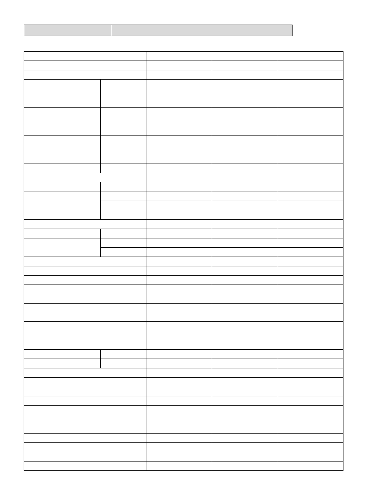
2-1. Unit specifications
Model No.
AS-09UR4SVNVG1
AS-12UR4SVNVG1 AS-12UR4SVGVG
Type T1, H/P, INVERTER T1, H/P, INVERTER T1, H/P, INVERTER
Ratings
Cooling Capacity W 2600(1200-3000) 3200(1200-3500) 3500(1400-3600)
Heating Capacity W 2900(1200-3500) 3400(1200-4000) 3550(1400-3800)
Rated Input-Cooling W 810(300-1450) 997(300-1550) 1090(430-1550)
Rated Input-Heating W 803(300-1500) 942(300-1600) 983(430-1600)
Moisture Removal L/H.r 0.9 1.5 1.5
Air Circulation m3/h 500 500 550
EER for Cooling W/W 3.21 3.21 3.21
COP for Heating W/W 3.61 3.61 3.61
Energy Class Cooling A A A
Energy Class Heatling A A A
Refrigerant R410A R410A R410A
Refrigerant charge volume
g 580 790 980
Indoor Unit Noise Level
High(dB (A)) 39 39 39
Low(dB (A)) 34 34 34
Outdoor Unit Noise Level dB (A) 52 52 53
Power Supply
Voltage, Frequency, Phase
V 220-240V~,50Hz,1P 220-240V~,50Hz,1P 220-240V~,50Hz,1P
Rated Current
Cooling (A) 3.8 4.5 4.8
Heating (A) 3.7 4.1 4.3
System
Compressor type Rotary Rotary Rotary
Compressor Model No. 39A23VPM&5JKE 39A23VPM&5JKE DA108M1C-10FZ2
Compressor MFG RECHI RECHI GMCC
Expansion Device Capillary Capillary Capillary
Evaporator
Copper tube and
Aluminum Fin
Copper tube and
Aluminum Fin
Copper tube and
Aluminum Fin
Condenser
Copper tube and
Aluminum Fin
Copper tube and
Aluminum Fin
Copper tube and
Aluminum Fin
Connecting Pipe Diameter
Liquid Pipe inch 1/4 1/4 1/4
Gas Pipe inch 3/8 3/8 3/8
Features
Display on Front Panel LED LED LED
LCD Wireless Remote Controller Yes Yes Yes
Removable and washable Panel Yes Yes Yes
Washable PP Filter Yes Yes Yes
24 Hours Timer Yes Yes Yes
3 Speed and Auto Indoor Fan Control Yes Yes Yes
Vertical Auto Swing Louver Yes Yes Yes
Manual Adjustable Horizontal Swing Louver
Yes Yes Yes
Sleep Operation Yes Yes Yes
Smart Function Yes Yes Yes
Page 5

22.. SSPPEECCIIFFIICCAATTIIOONNSS
Dimmer Yes Yes Yes
Super Function Yes Yes Yes
Compressor Indicator Yes Yes Yes
Auto Restart Yes Yes Yes
Other
Net Dimensions
WxHxD (mm)
Indoor Unit 750×250×190 750×250×190 820X270X210
Outdoor Unit 715×482×240 715×482×240 715×482×240
Net Weight (Kg)
Indoor Unit 8 8 8.5
Outdoor Unit 26 28 27
Packing Dimensions
WxHxD (mm)
Indoor Unit 800×325×245 800×325×245 880x340x285
Outdoor Unit 830×530×315 830×530×315 830×530×315
Gross Weight (Kg)
Indoor Unit 9 9 9.5
Outdoor Unit 28 30 29
Loading Capacity (20'/40'/40'HC ) 148/298/350 148/298/350 130/262/307
Test Standard EN 14511 EN 14511 EN 14511
Approvals CE CE CE
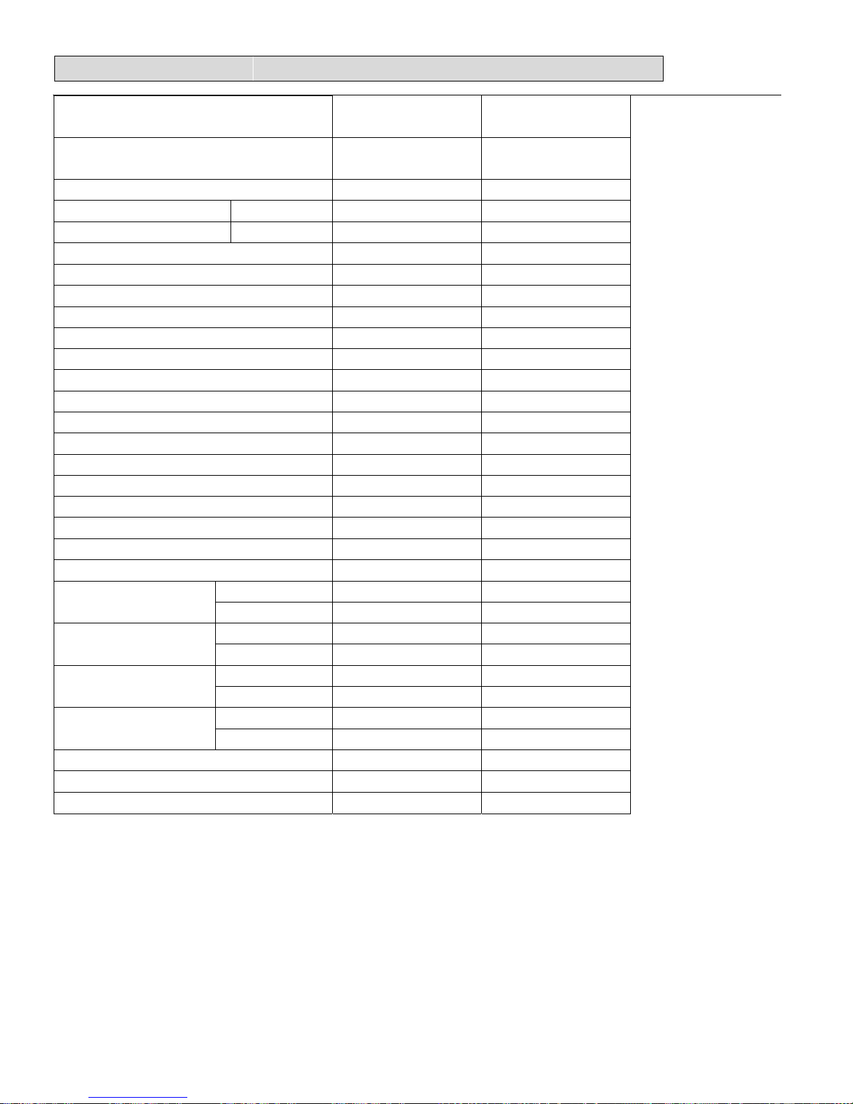
Model No.
AS-18UR4STVVG AS-24UR4SQJVG
Type T1, H/P, INVERTER T1, H/P, INVERTER
Ratings
Cooling Capacity W 5275(1817-5862) 7034(2198~7913)
Heating Capacity W 5569(1758-6741) 8206(2198~8792)
Rated Input-Cooling W 1550(480-2400) 2190(1400~3100)
Rated Input-Heating W 1540(480-2500) 2400(1400~3400)
Moisture Removal L/H.r 2.0 2.4
Air Circulation m3/h 900 950
EER for Cooling W/W 3.4 3.21
COP for Heating W/W 3.61 3.42
Energy Class Cooling A A
Energy Class Heatling A B
Refrigerant R410A R410A
Refrigerant charge volume
g 1700 1950
Indoor Unit Noise Level
High(dB (A)) 47 48
Low(dB (A)) 42 43
Outdoor Unit Noise Level dB (A) 56 58
Power Supply
Voltage, Frequency, Phase
V 220-240V~,50Hz,1P 220-240V~,50Hz,1P
Rated Current
Cooling (A) 7.6 10
Heating (A) 7.4 10.5
System
Compressor type Rotary Rotary
Compressor Model No. DA130S1C-20FZ C-7RVN153H0W
Compressor MFG GMCC SANYO
Expansion Device Capillary Capillary
Page 6
22.. SSPPEECCIIFFIICCAATTIIOONNSS
Evaporator
Copper tube and
Aluminum Fin
Copper tube and
Aluminum Fin
Condenser
Copper tube and
Aluminum Fin
Copper tube and
Aluminum Fin
Connecting Pipe Diameter
Liquid Pipe inch 1/4 3/8
Gas Pipe inch 1/2 5/8
Features
Display on Front Panel LED LED
LCD Wireless Remote Controller Yes Yes
Removable and washable Panel Yes Yes
Washable PP Filter Yes Yes
24 Hours Timer Yes Yes
3 Speed and Auto Indoor Fan Control Yes Yes
Vertical Auto Swing Louver Yes Yes
Manual Adjustable Horizontal Swing Louver
Yes Yes
Sleep Operation Yes Yes
Smart Function Yes Yes
Dimmer Yes Yes
Super Function Yes Yes
Compressor Indicator Yes Yes
Auto Restart Yes Yes
Other
Net Dimensions
WxHxD (mm)
Indoor Unit 920x313x226 1035×313×220
Outdoor Unit 830x637x285 832×702×312
Net Weight (Kg)
Indoor Unit 11 13
Outdoor Unit 45 56
Packing Dimensions
WxHxD (mm)
Indoor Unit 1010x380x300 1130×390×310
Outdoor Unit 980×680×400 980x770x420
Gross Weight (Kg)
Indoor Unit 14 16
Outdoor Unit 49 60
Loading Capacity (20'/40'/40'HC ) 79/162/180 66/135/150
Test Standard EN 14511 EN 14511
Approvals CE CE
Page 7

33.. IINNSSTTAALLLLAATTIIOON
N
1、How to choose an air conditioner:
a. Choice for reference: 150-170W/㎡ for average rooms;
b. Choice for reference: 160-200W/㎡ for small size offices;
c. Choice for reference: 220-350W/㎡ for restaurants;
d. Choice for reference: 200-300W/㎡ for entertaining venues;
e. Choice for reference: 220-280W/㎡ for the top floor.
Note:1W = 3.412btu.
2、Indoor Unit:
For indoor unit installation, the distance between its top and the ceiling shall
not be less than 10 cm -20 cm, and the distance from the ground should be
between 2m to 2.6m. Also the wallboard must be smooth and straight, with its
supporting force of not less than 60 kg.
The location for installing the indoor unit shall be far away from heat source,
the space between it and the door or window should exceed 0.6m
3、Outdoor Unit:
The air conditioner outdoor unit should not occupy public sidewalks, the
distance between the mounting bracket installed along the road (on condition that
the mounting bracket does not affect the public access, it can be installed
horizontally) and the ground must exceed 2.5m. Also we shall remember that: a.
the air flow must run freely . b. we should protect famous ancient buildings during
installation. c. the installation does not affect the traffic.
The distance between air outlet of outdoor unit and the opposite object should
be more than 1 meter, otherwise the machine would stop running because of
overload by heat yield failure.
If the outdoor unit was opposite the resident's door or window, you should
install the machine as far as possible away from the adjacent doors windows and
plants, and the distance shall not be less than the following values: for the r ated
cooling capacity not more than 4.5KW, the distance should be 3m.; for the rated
cooling capacity more than 4.5KW, the distance should be 4m.
It should remember to avoid installing at places where the natural
environment is harsh, such as heavy fumes and wind, direct sunlight or
high-temperature and heat, together with the place where children easily reach.
4. The Unit:
When installing the air conditioner, the outdoor unit should be below the
indoor unit so as to facilitate circle of refrigerant and refrigeration oil .(1)The
height difference between wall mounted indoor unit and the outdoor unit is
generally not more than 5 meters. (2)The connection pipe can't exceed 5 meters,
and the longest is 15 meters. When the length exceeds 5 meters, 20g fluoride is
required to be added for each exceeding 1m.
Page 8
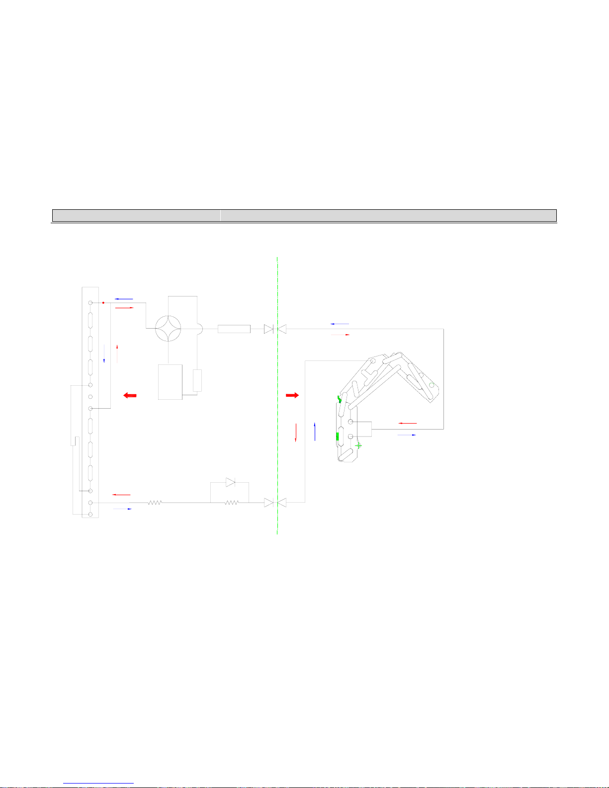
44.. RREEFFRRIIGGEERRAANNTT FFLLOOWW DDIIAAGGRRAAMM
4-1. Refrigerant flow diagram :
CAPILLARY
COMPRESSOR
CHECK VALVE ASS'Y
CAPILLARY
CONDENSER
EVAPORATOR
OUTDOOR
INDOOR
出2
Page 9
44.. RREEFFRRIIGGEERRAANNTT FFLLOOWW DDIIAAGGRRAAMM
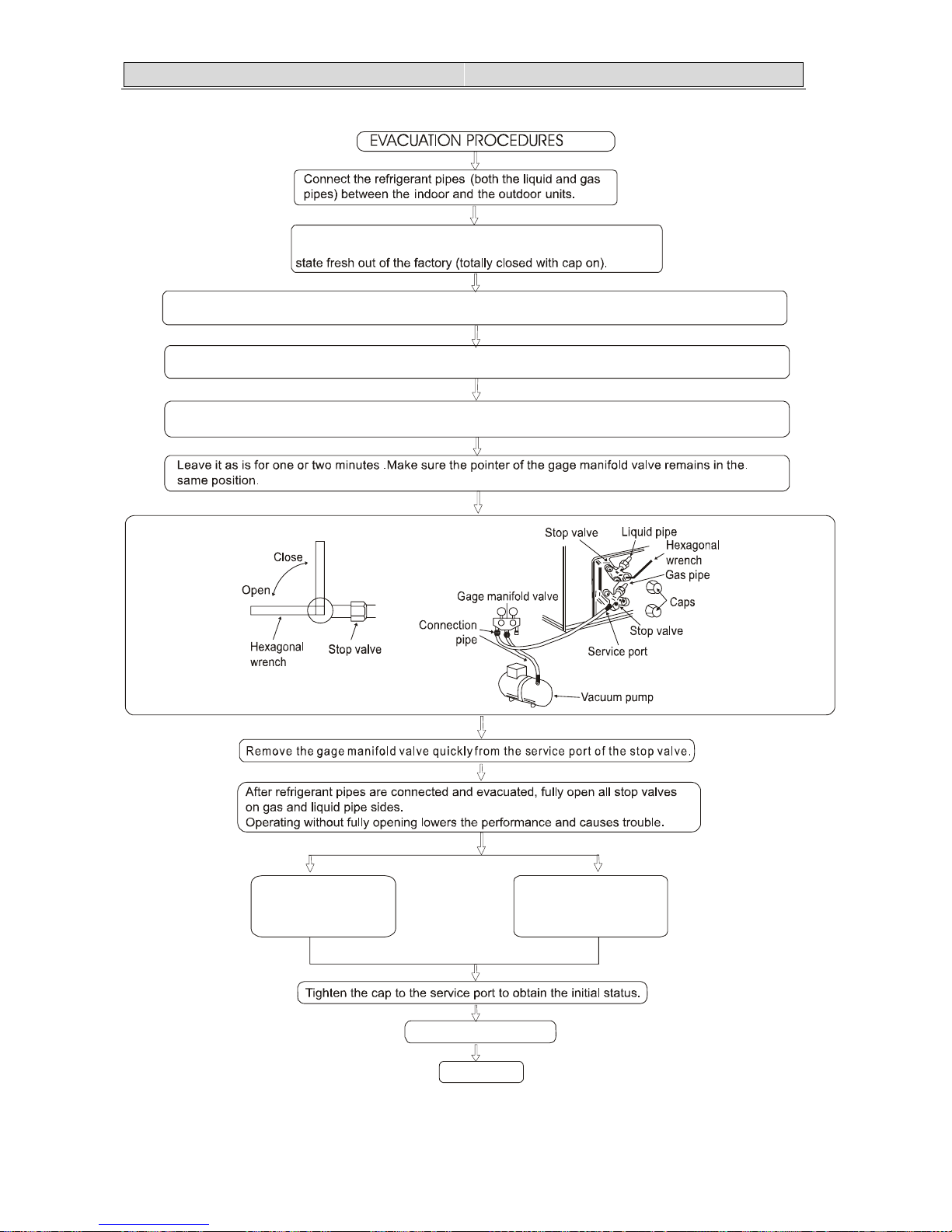
4-2. Evacuation procedures:
Remove the service port cap of the stop valve on the side of the
outdoor unit gas pipe. (The stop valve will not work in its initial
Connect the gage manifold valve and the vacuum pump to the service port of the stop valve on the gas pipe
side of the outdoor unit.
Run the vacuum pump for more than 15 minutes and at this time confirm that the pressure gage indicates
-0.1 Mpa (-76 cmHg).
Check the vacuum with the gage manifold valve, then close the gage manifold valve, and stop the
vacuum pump.
Pipe length
5m and 7m maximum
No gas charge is
needed.
Pipe length
exceeding 5m and 7m
Charge the prescribed
amount of gas.
Retighten the cap.
Leak test
Page 10
55.. EELLEECCTTRRIICCAALL DDAATTAA
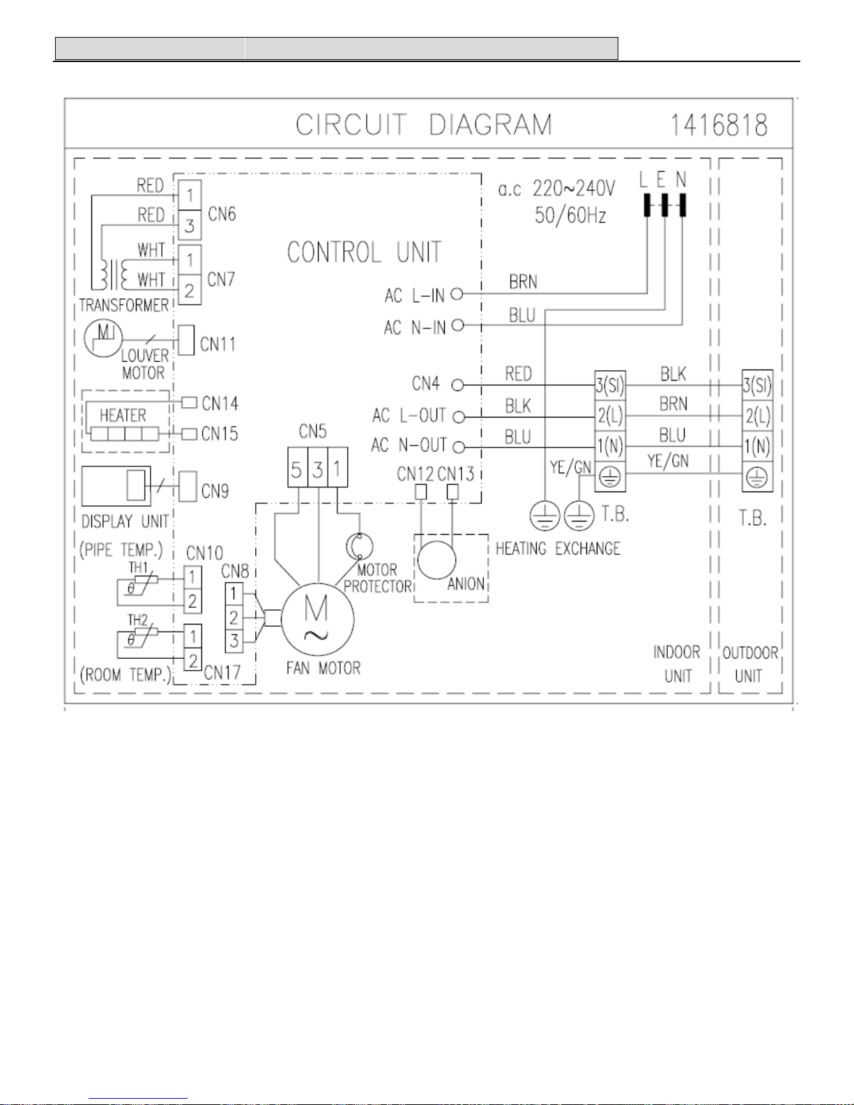
5-1.Electrical wiring diagrams
INDOOR:
(1)AS-09UR4SVNVG1、AS-12UR4SVNVG1(indoor):
Page 11
55.. EELLEECCTTRRIICCAALL DDAATTAA
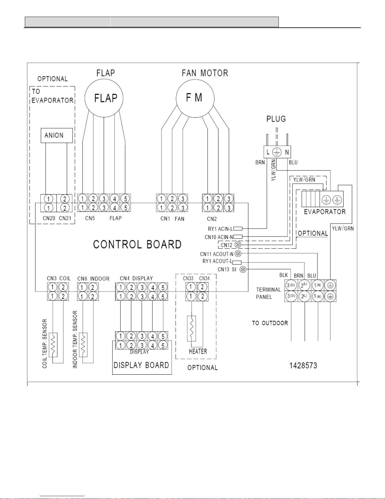
(2)AS-12UR4SVGVG(indoor):
Page 12

55.. EELLEECCTTRRIICCAALL DDAATTAA
(3)AS-18UR4STVVG(indoor):
Page 13

55.. EELLEECCTTRRIICCAALL DDAATTAA
(4)AS-24UR4SQJVG(indoor)
Page 14

55.. EELLEECCTTRRIICCAALL DDAATTAA
OUTDOOR
(5)AS-09UR4SVNVG1、AS-12UR4SVNVG1、AS-12UR4SVGVG(outdoor)
Page 15

55.. EELLEECCTTRRIICCAALL DDAATTAA
(6)AS-18UR4STVVG(outdoor):
Page 16

55.. EELLEECCTTRRIICCAALL DDAATTAA
(7)AS-24UR4SQJVG(outdoor)
Page 17

55.. EELLEECCTTRRIICCAALL DDAATTAA
5-2. Sensor parameter
1. THE PARAMETER OF OUTDOOR COMPRESSOR TEMPERATURE SENSOR:
(R
0
=187.25K±6.3%;R
100
=3.77K±2.5K;B=3979±1%)
T(℃) R(KΩ) V(v) DEC HEX T(℃) R(KΩ) V(v) DEC HEX T(℃) R(KΩ ) V(v) DEC HEX
-30 966.1 0.1014 5 5 26 55.46 1.3252 68 44 82 6.662 3.7507 191
BF
-29 910.3 0.1075 5 5 27 53.11 1.3678 70 46 83 6.446 3.7813 193
C1
-28 858 0.1139 6 6 28 50.86 1.4112 72 48 84 6.239 3.8111 194
C2
-27 809 0.1206 6 6 29 48.72 1.4552 74
4A
85 6.039 3.8404 196
C4
-26 763.1 0.1277 7 7 30 46.68 1.4997 76
4C
86 5.846 3.8691 197
C5
-25 720 0.1351 7 7 31 44.74 1.5446 79
4F
87 5.661 3.8970 199
C7
-24 679.6 0.1429 7 7 32 42.89 1.5901 81 51 88 5.482 3.9243 200
C8
-23 641.7 0.1511 8 8 33 41.13 1.6359 83 53 89 5.309 3.9512 202
CA
-22 606.1 0.1597 8 8 34 39.44 1.6824 86 56 90 5.143 3.9773 203
CB
-21 572.7 0.1687 9 9 35 37.84 1.7289 88 58 91 4.982 4.0029 204
CC
-20 541.3 0.1782 9 9 36 36.3 1.7762 91
5B
92 4.827 4.0279 205
CD
-19 511.7 0.1881 10
A
37 34.84 1.8235 93
5E
93 4.678 4.0522 207
CF
-18 484 0.1984 10
A
38 33.44 1.8713 95
5F
94 4.534 4.0760 208
D0
-17 457.9 0.2092 11
B
39 32.11 1.9190 98 62 95 4.395 4.0992 209
D1
-16 433.3 0.2206 11
B
40 30.83 1.9673 100 64 96 4.261 4.1218 210
D2
-15 410.2 0.2325 12
C
41 29.61 2.0157 103 67 97 4.132 4.1439 211
D3
-14 388.5 0.2448 12
C
42 28.45 2.0640 105 69 98 4.007 4.1655 212
D4
-13 368 0.2577 13
D
43 27.34 2.1124 108
6C
99 3.886 4.1866 214
D6
-12 348.7 0.2712 14
E
44 26.27 2.1612 110
6E
100 3.77 4.2070 215
D7
-11 330.5 0.2853 15
F
45 25.25 2.2099 113 71 101 3.658 4.2269 216
D8
-10 313.4 0.2999 15
F
46 24.28 2.2584 115 73 102 3.549 4.2465 217
D9
-9 297.2 0.3153 16 10 47 23.35 2.3068 118 76 103 3.444 4.2655 218
DA
-8 281.9 0.3312 17 11 48 22.46 2.3552 120 78 104 3.343 4.2839 218
DA
-7 267.5 0.3478 18 12 49 21.6 2.4038 123
7B
105 3.15 4.3197 220
DC
-6 253.9 0.3651 19 13 50 20.79 2.4516 125
7D
106 3.059 4.3367 221
DD
-5 241.1 0.3830 20 14 51 20.01 2.4994 127
7F
107 2.97 4.3535 222
DE
-4 229 0.4016 20 14 52 19.26 2.5471 130 82 108 2.884 4.3699 223
DF
-3 217.6 0.4209 21 15 53 18.54 2.5947 132 84 109 2.802 4.3856 224
E0
-2 206.8 0.4409 22 16 54 17.85 2.6420 135 87 110 2.721 4.4012 224
E0
-1 196.6 0.4617 24 17 55 17.19 2.6889 137 89 111 2.721 4.4012 224
E0
0 186.9 0.4833 25 18 56 16.56 2.7352 139
8B
112 2.644 4.4162 225
E1
1 177.8 0.5056 26 19 57 15.96 2.7809 142
8E
113 2.569 4.4309 226
E2
2 169.2 0.5285 27
1A
58 15.38 2.8265 144 90 114 2.496 4.4452 227
E3
3 161 0.5525 28
1B
59 14.82 2.8719 146 92 115 2.426 4.4591 227
E3
4 153.3 0.5770 29
1C
60 14.29 2.9163 149 95 116 2.358 4.4727 228
E4
5 146 0.6024 31
1E
61 13.78 2.9603 151 97 117 2.292 4.4859 229
E5
6 139 0.6289 32
1F
62 13.28 3.0048 153 99 118 2.228 4.4988 229
E5
7 132.5 0.6557 33 21 63 12.81 3.0479 155
9B
119 2.167 4.5112 230
E6
8 126.3 0.6835 35 23 64 12.36 3.0902 158
9E
120 2.107 4.5235 231
E7
9 120.4 0.7123 36 24 65 11.93 3.1319 160
A0
121 2.049 4.5354 231
E7
10 114.8 0.7418 38 26 66 11.51 3.1736 162
A2
122 2.049 4.5354 231
E7
11 109.5 0.7722 39 27 67 11.11 3.2144 164
A4
123 1.994 4.5467 232
E8
12 104.4 0.8039 41 29 68 10.73 3.2541 166
A6
124 1.887 4.5689 233
E9
13 99.66 0.8357 43
2B
69 10.36 3.2938 168
A8
125 1.836 4.5796 234
EA
14 95.13 0.8686 44
2D
70 10 3.3333 170
AA
126 1.787 4.5899 234
EA
15 90.82 0.9024 46
2C
71 9.659 3.3717 172
AC
127 1.739 4.6000 235
EB
16 86.74 0.9369 48
2E
72 9.331 3.4094 174
AE
128 1.693 4.6098 235
EB
17 82.85 0.9723 50 32 73 9.016 3.4464 176
B0
129 1.649 4.6192 236
EC
18 79.16 1.0085 51 33 74 8.712 3.4829 178
B2
130 1.605 4.6286 236
EC
19 75.65 1.0455 53 35 75 8.421 3.5185 179
B3
20 72.32 1.0832 55 37 76 8.14 3.5537 181
B5
21 69.15 1.1217 57 39 77 7.869 3.5882 183
B7
22 66.13 1.1610 59
3B
78 7.609 3.6220 185
B9
23 63.27 1.2009 61
3D
79 7.359 3.6551 186
BA
24 60.54 1.2416 63
3F 80
7.118 3.6876 188
BC
25 57.94 1.2830 65 41 81 6.885 3.7195 190
BE
Page 18

55.. EELLEECCTTRRIICCAALL DDAATTAA
2. THE PARAMETER OF THE OUTDOOR COIL AND OUTDOOR SENSOR:(R0=15K±2%;B=3450±2%)
T(℃) R(KΩ) V(v) DEC HEX T(℃) R(KΩ) V(v) DEC HEX T(℃) R(KΩ) V(v) DEC HEX
-30 67.94 0.3235 16 10 18 6.962 2.0151 103 67 66 1.297 3.9186 200 C8
-29 64.25 0.3408 17 11 19 6.688 2.0636 105 69 67 1.258 3.9443 201 C9
-28 60.79 0.3588 18 12 20 6.427 2.1120 108 6C 68 1.22 3.9696 202 CA
-27 57.53 0.3776 19 13 21 6.178 2.1603 110 6E 69 1.184 3.9939 204 CC
-26 54.48 0.3971 20 14 22 5.939 2.2089 113 71 70 1.149 4.0178 205 CD
-25 51.6 0.4174 21 15 23 5.712 2.2570 115 73 71 1.116 4.0406 206 CE
-24 48.9 0.4384 22 16 24 5.494 2.3053 118 76 72 1.083 4.0636 207 CF
-23 46.35 0.4603 23 17 25 5.286 2.3533 120 78 73 1.051 4.0862 208 D0
-22 43.96 0.4829 25 19 26 5.086 2.4014 122 7A 74 1.021 4.1077 209 D1
-21 41.7 0.5065 26 1A 27 4.896 2.4489 125 7D 75 0.9914 4.1290 211 D3
-20 39.58 0.5307 27 1B 28 4.714 2.4963 127 7F 76 0.963 4.1497 212 D4
-19 37.58 0.5558 28 1C 29 4.539 2.5436 130 82 77 0.9354 4.1701 213 D5
-18 35.69 0.5818 30 1E 30 4.372 2.5904 132 84 78 0.9088 4.1898 214 D6
-17 33.91 0.6087 31 1F 31 4.212 2.6369 134 86 79 0.8831 4.2091 215 D7
-16 32.23 0.6363 32 20 32 4.059 2.6830 137 89 80 0.8582 4.2280 216 D8
-15 30.65 0.6648 34 22 33 3.912 2.7288 139 8B 81 0.8342 4.2463 217 D9
-14 29.15 0.6942 35 23 34 3.772 2.7738 141 8D 82 0.8109 4.2643 217 D9
-13 27.74 0.7244 37 25 35 3.637 2.8188 144 90 83 0.7884 4.2818 218 DA
-12 26.4 0.7556 39 27 36 3.508 2.8631 146 92 84 0.7666 4.2988 219 DB
-11 25.14 0.7875 40 28 37 3.384 2.9070 148 94 85 0.7455 4.3155 220 DC
-10 23.95 0.8202 42 2A 38 3.265 2.9504 150 96 86 0.725 4.3318 221 DD
-9 22.82 0.8539 44 2C 39 3.151 2.9932 153 99 87 0.7053 4.3476 222 DE
-8 21.75 0.8885 45 2D 40 3.041 3.0358 155 9B 88 0.6861 4.3631 223 DF
-7 20.74 0.9237 47 2F 41 2.936 3.0775 157 9D 89 0.6676 4.3781 223 DF
-6 19.79 0.9596 49 31 42 2.835 3.1188 159 9F 90 0.6496 4.3929 224 E0
-5 18.88 0.9966 51 33 43 2.739 3.1590 161 A1 91 0.6323 4.4071 225 E1
-4 18.02 1.0343 53 35 44 2.646 3.1990 163 A3 92 0.6156 4.4209 225 E1
-3 17.2 1.0731 55 37 45 2.556 3.2387 165 A5 93 0.5993 4.4345 226 E2
-2 16.43 1.1122 57 39 46 2.471 3.2771 167 A7 94 0.5836 4.4477 227 E3
-1 15.7 1.1520 59 3B 47 2.388 3.3155 169 A9 95 0.5683 4.4606 227 E3
0 15 1.1929 61 3D 48 2.309 3.3528 171 AB 96 0.5535 4.4732 228 E4
1 14.34 1.2342 63 3F 49 2.233 3.3896 173 AD 97 0.5391 4.4855 229 E5
2 13.71 1.2765 65 41 50 2.159 3.4262 175 AF 98 0.5251 4.4975 229 E5
3 13.11 1.3195 67 43 51 2.089 3.4615 177 B1 99 0.5115 4.5093 230 E6
4 12.55 1.3623 69 45 52 2.021 3.4965 178 B2 100 0.4983 4.5207 231 E7
5 12.01 1.4063 72 48 53 1.956 3.5306 180 B4 101 0.4855 4.5319 231 E7
6 11.5 1.4506 74 4A 54 1.893 3.5644 182 B6 102 0.4731 4.5427 232 E8
7 11.01 1.4959 76 4C 55 1.832 3.5977 183 B7 103 0.461 4.5534 232 E8
8 10.55 1.5410 79 4F 56 1.774 3.6299 185 B9 104 0.4492 4.5638 233 E9
9 10.1 1.5878 81 51 57 1.718 3.6616 187 BB 105 0.4378 4.5739 233 E9
10 9.684 1.6338 83 53 58 1.664 3.6926 188 BC 106 0.4268 4.5838 234 EA
11 9.284 1.6805 86 56 59 1.612 3.7231 190 BE 107 0.416 4.5934 234 EA
12 8.903 1.7276 88 58 60 1.562 3.7528 191 BF 108 0.4055 4.6029 235 EB
13 8.54 1.7749 91 5B 61 1.513 3.7824 193 C1 109 0.3953 4.6121 235 EB
14 8.194 1.8226 93 5D 62 1.467 3.8106 194 C2 110 0.3854 4.6211 236 EC
15 7.864 1.8704 95 5F 63 1.422 3.8386 196 C4
16 7.549 1.9185 98 62 64 1.379 3.8658 197 C5
17 7.249 1.9667 100 64 65 1.337 3.8927 199 C7
Page 19

55.. EELLEECCTTRRIICCAALL DDAATTAA
3.THE PARAMETER OF THE INDOOR COIL AND INDOOR ROOM SENSOR:
(R
0
=15K;B=3450)
T(℃) R(KΩ)
V(V) AD
T(℃) R(KΩ)
V(V) AD
T(℃)R(KΩ)
V(V) AD
-20 38.32 0.5469 112 14 8.276 1.8115 371 48 2.347 3.335 683
-19 36.47 0.5713 117 15 7.946 1.8604 381 49 2.269 3.374 691
-18 34.72 0.5957 122 16 7.632 1.9043 390 50 2.195 3.4082 698
-17 33.06 0.6201 127 17 7.331 1.9531 400 51 2.126 3.4424 705
-16 31.49 0.6494 133 18 7.044 2.002 410 52 2.058 3.4766 712
-15 30 0.6787 139 19 6.769 2.0508 420 53 1.992 3.5107 719
-14 28.59 0.708 145 20 6.507 2.0947 429 54 1.928 3.5449 726
-13 27.26 0.7373 151 21 6.256 2.1436 439 55 1.867 3.5791 733
-12 25.99 0.7666 157 22 6.017 2.1924 449 56 1.808 3.6133 740
-11 24.79 0.7959 163 23 5.788 2.2412 459 57 1.751 3.6426 746
-10 23.65 0.8301 170 24 5.568 2.29 469 58 1.696 3.6719 752
-9 22.57 0.8594 176 25 5.359 2.334 478 59 1.644 3.7061 759
-8 21.55 0.8936 183 26 5.158 2.3828 488 60 1.593 3.7354 765
-7 20.57 0.9277 190 27 4.966 2.4316 498 61 1.544 3.7646 771
-6 19.65 0.9668 198 28 4.782 2.4805 508 62 1.497 3.7939 777
-5 18.77 1.001 205 29 4.606 2.5244 517 63 1.451 3.8184 782
-4 17.94 1.04 213 30 4.437 2.5732 527 64 1.407 3.8477 788
-3 17.15 1.0742 220 31 4.276 2.6172 536 65 1.365 3.877 794
-2 16.4 1.1133 228 32 4.121 2.666 546 66 1.324 3.9014 799
-1 15.68 1.1523 236 33 3.972 2.71 555 67 1.284 3.9258 804
0 15 1.1914 244 34 3.83 2.7539 564 68 1.246 3.9502 809
1 14.35 1.2354 253 35 3.694 2.7979 573 69 1.209 3.9746 814
2 13.74 1.2744 261 36 3.563 2.8418 582 70 1.174 3.999 819
3 13.15 1.3184 270 37 3.437 2.8857 591 71 1.133 4.0283 825
4 12.59 1.3574 278 38 3.317 2.9297 600 72 1.1 4.0527 830
5 12.06 1.4014 287 39 3.201 2.9736 609 73 1.068 4.0723 834
6 11.56 1.4453 296 40 3.09 3.0176 618 74 1.037 4.0967 839
7 11.07 1.4893 305 41 2.984 3.0566 626 75 1.008 4.1162 843
8 10.62 1.5332 314 42 2.881 3.1006 635 76 0.979 4.1357 847
9 10.18 1.5771 323 43 2.783 3.1396 643 77 0.951 4.1602 852
10 9.761 1.626 333 44 2.689 3.1787 651 78 0.924 4.1797 856
11 9.363 1.6699 342 45 2.598 3.2178 659 79 0.898 4.1992 860
12 8.984 1.7188 352 46 2.511 3.2568 667 80 0.873 4.2188 864
13 8.622 1.7627 361 47 2.427 3.2959 675
Page 20

66.. CCOONNTTRROOLL MMOODDE
E
6-1. Major general technical parameters
6-1-1 Conditionings for operation: Ambient temperatures: (-15 - +45 ℃),
relative humidity (45 - 85%).
6-1-2 Remote receiver distance: 8 m.
6-1-3 Remote receiver angle: Less than 80 degrees.
6-1-4 Temperature control accuracy: ±1℃.
6-1-5 Time error: Less than 1%.
6-1-6 The power supply for the air conditioner is a.c 220V, 50Hz, with its
fluctuation in the range of (198~264V).
6-2. Functions of the controller
6-2-1 Display panel
I. Control functions of the remote controller (See operating and
installation manual)
II. Display of the indoor unit
Information on the screen:
Displaying Scheme:
Temperature display:Display set temperature or indoor temperature ,
and display fault code in trouble indicating. An error code is displayed
according to the signal from the indoor CPU. The error code will flash for
5 seconds while displayed.
Running indicator:It is on during operation. It flashes in 10s after the
sleep modehas been setted.
TIMER indicator:When the timer mode works, the indicator will be
lighted.
Sleep indicator:When the sleep mode works, the indicator will be
lighted.
Compressor indicator:It lights up when compressor is running.
Remote control receiver: This section receives signals from the
remote controller.
6-3. Control function
6-3-1 Emergency switch
6-3-1-1 Press the emergency switch once to turn on the machine and
press it again to turn off the machine; in the automatic mode, the indoor
control temperature is set at 24℃ with the indoor fan speed setting is
automatic and the flaps sweep.
6-3-1-2 When the machine is turned on (in the OFF condition), press and
hold the emergency switch for 5 seconds, the buzzer rings for 3 times
and the controller starts in the trial operation. The trial operation is the
Page 21

66.. CCOONNTTRROOLL MMOODDE
E
forced cooling with the indoor fan speed being set at high speeds, the
flaps sweeping and the air conditioner’s operation is irrelevant with room
temperatures.
6-3-1-3 If a remote signal has been received during the emergency run,
the machine will operate upon the command of such a remote signal.
6-3-2 Operator-machine communication
6-3-2-1 The air conditioner has a thermal sensor to detect room
temperatures. Some remote controller is equipped with a thermal sensor
(Such remote controller has the function of man-machine
communication. For details, refer to the section for the remote
controller). In addition, there is a thermal sensor at the indoor air inlet.
In the case where the remote controller is equipped with a thermal
sensor, the default setting for room temperatures is subject to the
detection by the remote controller. The remote controller detects the
room temperature once every 20 seconds, and automatically transmits a
signal at an interval of 3 minutes or when a change in the room
temperature is detected. If the indoor control unit has not received a
remote signal for more than 10 minutes, the control function will be
automatically switched over to the thermal sensor on the indoor unit.
6-3-2-2 Neither the turning on nor turning off operation will cancel the
operator-machine communication function.
6-3-2-3 In default, the air conditioner is set to start the
operator-machine communication function.
6-3-3 Timer function
6-3-3-1 Timer on: When set to start in a time by the remote controller,
the air conditioner starts in the timer on condition. When the set time is
up, the air conditioner will turn on and operates in the preset conditions
after receiving a signal from the remote controller. If the air conditioner
Page 22

66.. CCOONNTTRROOLL MMOODDE
E
has not received a signal from the remote controller when the set time is
up, it will automatically start and operate in the preset conditions.
6-3-3-2 Timer off: When set to stop in a set time by the remote controller,
the air conditioner will start in the timer off condition. When the set time
is up, the air conditioner will turn off after receiving a signal from the
remote controller. If the air conditioner has not received a signal from the
remote controller when the set time is up, it will turn off automatically.
6-3-3-3 Neither the turning on nor turning off operation will cancel the
timer function (Some remote controller has a simple one-hour timer off
function and excludes this operation).
6-3-4 Sleep
6-3-4-1 In the heating, cooling or dehumidifying mode, press the “Sleep”
button on the remote controller to start or cancel the sleep function in
turn, and at the same time the sleep icon on the display screen will be on
or off accordingly.
6-3-4-2 According to the different needs, there are four different sleep
modes to choose. During the time of sleep mode, the set temperature will
change automatically.
6-3-4-3 In default, the setting is to cancel the sleep function. Turning off
the unit will also cancel the sleep function.
6-3-4-4 The sleep function is valid for 8 hours. The air conditioner will
turns off and cancel the sleep function after the sleep function works for
8 hours.
6-3-5 High efficient run function (This function is invalid)
In the heating (except for the single cooling unit), cooling or
dehumidifying mode, it may be set for high efficient run with the indoor
fan speed changed to the high efficient fan speed and the compressor
operating at the highest frequency as available. If the display screen can
display the frequency, the frequency displayed on the screen is up to the
maximum. It will restore to the previous run state after 15 minutes
Page 23

66.. CCOONNTTRROOLL MMOODDE
E
operation automatically.
6-3-6 Automatic run (SMART) mode
If there is no man-machine communication function after the unit is
started, the indoor fan operates at the ultra-low flowrate for 20 seconds
before selecting a run mode; the room temperatures are detected during
this period for the selection of a run mode.
In the first operation:
a. When T
room
– T
set
>3℃, it starts in the cooling mode;
b. When -3℃≤T
room
– T
set
≤3℃, it starts in the ventilation run mode;
c. When T
room
– T
set
<-3℃, it starts in the heating mode.
After the first run in the cooling or heating mode, the mode will be
changed as the following:
a. When T
room
– T
set
>3℃, it will be changed to the cooling mode;
b. When T
room
– T
set
<-3℃, it will be changed to the heating mode;
c. When these conditions are not met, it will remain in the previous run
mode.
When the temperature setting is changed, re-judgment will be made for
the run mode according to the descriptions mentioned above; when the
compressor is halted for 10 minutes, the re-judgment will be made for
the run mode.
6-3-6-1 Switch between the cooling and heating mode:
T
ambient
t
set
+3
t
set
t
set
-3
Cooling Heating mode Cooling
Page 24

66.. CCOONNTTRROOLL MMOODDE
E
6-3-6-2 Cooling→heating turnover operation
Cooling→heating: the compressor stops; 50 s later the 4-way valve is
activated and 3 minutes more the compressor turns on.
Heating→cooling: the compressor stops, 50 s later the 4-way valve is
interrupted and 3 minutes more the compressor turns on.
6-3-6-3 There is temperature compensation during the auto-run, which
is same as cooling and heating.
6-3-7 Cooling-run mode
5-3-7-1 Temperature compensation
Principle for compensation: The compensation is available only if the
proper sensor is used and it is not available when it is subject to the
sensor on the remote controller.
6-3-7-2 Outdoor Fan
The outdoor fan’s speeds are divided into two levels which can be
changed over according to outdoor ambient temperatures.
When operating at a fixed frequency, the outdoor fan is forced to operate
at the high speed.
6-3-7-3 Indoor fan
When the fan speed is set at the high, medium and low fan speeds, the
fan runs at a preset speed. When the fan speed setting is automatic, the
fan speed is set based on the difference in room temperatures.
T
room-Tset
Indoor fan speed
T
room-Tset
≤20C
Low
20C <T
room-Tset
<40C
Medium
T
room-Tset
≥40C
High
6-3-7-4 Prevention against condensation and insufficient heat exchange
at the low indoor fan speed.
When the indoor fan speed is set at the low fan speed, the compressor’s
power is restricted as in the low temperature cooling.
6-3-7-5 4-way valve
State: It is interrupted in cooling.
Switchover: When initially powered on for cooling, the 4-way valve is
interrupted immediately.
When the heating is changed to the cooling, it needs an interval of 50
seconds for the 4-way valve to change over from being activated to being
interrupted.
Page 25

66.. CCOONNTTRROOLL MMOODDE
E
6-3-8 Heating-run mode
6-3-8-1 Temperature compensation
Principle for compensation: The compensation is available only if the
proper sensor is used and it is not available when it is subject to the
sensor on the remote controller or line controller.
6-3-8-2 Indoor fan
The fan speed is set at the high, medium or low fan speed, it operates at
a preset speed (in the cold air prevention, it is forced to run at the
ultra-low flowrate or stop).
When the fan speed is set in the auto-run, the fan speed setting is made
according to the room temperature differences (except for the cold air
prevention).
T
set-Troom
Indoor Fan Speed
T
set-Troom
≤20C
Low
20C <T
set-Troom
<40C
Medium
T
set-Troom
≥40C
High
6-3-8-3 Cold air prevention
In the heating-run, to prevent the indoor fan from blowing cold air, the
indoor fan speed is different from the set speed after turning on
air-conditioner.
6-3-8-4 Residual heat blowing off
When the compressor is turned off in the heating run, the indoor fan does
not stop at once, but until the indoor evaporator temperature is below
230C, but for 30 seconds at the latest.
6-3-8-5 Outdoor fan
The outdoor fan speeds are divided into three levels which can be
changed over according to outdoor ambient temperatures.
6-3-8-6 4-way valve
State: It is electrified in heating.
Switchover: When initially powered on for heating, the 4-way valve is
activated immediately.
In the change from cooling to heating, it needs an interval of 50 seconds
for the 4-way valve to change over from being interrupted to being
activated.
Page 26

66.. CCOONNTTRROOLL MMOODDE
E
Tset
16
0
C
6-3-9 Dehumidifying mode
The dehumidifying mode is illustrated as follows:
Dehumidifying area I: Operation at the frequency in the range (30–80 Hz)
according to Δt (T
indoor ambient-Tset
).
Δt(℃)
f(Hz)
0 30
0.5 30
1 40
1.5 50
≥2 60
Efficient 80
Dehumidifying area II: The compressor stops for 5 minutes and
operators for 5 minutes at the lowest frequency.
Dehumidifying area III: The compressor stops.
6-3-10 Air Blowing mode
The outdoor unit does not work while the indoor fan runs with the fan
speed selectable at the auto, low, medium and high speeds.
Time
I II III
Indoor Ambient Temperature
Page 27

66.. CCOONNTTRROOLL MMOODDE
E
When being auto, the fan speed is determined in the cooling mode (with
the temperature setting of 240C in default).
The high, medium and low fan speeds are same with that in the cooling
mode.
6-3-11 Compressor operating state indication
When the compressor is in operation, The 3 LED indicator lights on
the control panel of the outdoor unit indicates the causes of the
restriction on the compressor’s current operating frequency.
Symbols for indicator light:: ★: ON Ο: flashing ×: OFF
LED1 LED2 LED3
The cause of the restriction on the
compressor’s current operating frequency
1
Ο Ο Ο
Normal frequency ascent and descent with no
restriction on the frequency
2
× ×
★
Frequency descent or restriction on frequency
ascent caused by over current
3
×
★ ★
Frequency descent or restriction on frequency
ascent caused by anti-freeze in cooling or
overload control in heating
4
★
×
★
Frequency descent or restriction on frequency
ascent caused by too high compressor
discharge temperature
5
×
★
×
Restriction on maximum operation operating
frequency caused by too low voltage on the
supply circuit
6
★ ★ ★
Operating at a fixed frequency (when in a
capacity measurement or forced operation at
a fixed frequency.)
8
★
× ×
Communication frequency drops.
6-3-12 Special notes
6-3-12-1 The outdoor unit of this model is electrified by the indoor unit
control. After the system starts to operate, the indoor unit supplies the
outdoor unit (except for the ventilation mode). If the EEPROM data is
read correctly after turning on the power, the indoor unit’s beeper rings
one time, or if it is not the case the beeper will ring two times and the
Page 28

66.. CCOONNTTRROOLL MMOODDE
E
system cannot be started. Normally, when the indoor unit receives a
control signal from the remote controller and emergency button, the
system will be started and the beeper will ring two times, and in other
cases, the beeper will ring one time.
6-3-12-2 This model can achieve the power interruption restoration
function by the selection of the EEPROM data. The power interruption
restoration is applied only for the basic functions (turning ON and OFF,
setting temperatures, modes, fan speeds and flap’s position) and not for
other special functions such as sleep, timing and power-saving run.
Page 29

77 TTRROOUUBBLLEE SSHHOOOOTTIINNGG
7-1. Trouble alarm
Trouble List
Indication on the outdoor unit
When the compressor is interrupted, the outdoor LEDs are used
to indicate the troubles listed below:
Symbols for indicator lights: ★: ON Ο: flashing ×: OFF
LED1 LED2 LED3 Troubles
1
× × ×
Normal
2
× ×
★
Unused
3
×
★
×
Outdoor heat exchanger temperature sensor
be protected
4
★
× ×
Compressor temperature sensor
short-circuited, open circuited or the
corresponding test circuit in trouble
5
★
×
★
Outdoor heat exchanger temperature sensor
short-circuited, open circuited or the
corresponding test circuit in trouble
6
★ ★
×
Outdoor atmosphere temperature sensor
short-circuited, open circuited or the
corresponding test circuit in trouble
9
× × Ο
Signal communication abnormal (indoor –
outdoor)
10
× Ο ×
Power module (IPM)protection
11
★
Ο
★
Maximum current control
12
★
Ο ×
Current overload control
13
× Ο
★
Compressor discharge temperature too high
14
★ ★
Ο
Over and under-voltage control
18
×
★
Ο
Compressor housing temperature too high
19
★ ★ ★
Outdoor memory in trouble
20
× Ο Ο
Indoor heat exchanger temperature sensor
be protected
22
Ο Ο ×
DC compressor fails to start
23
Ο × Ο
DC compressor out of step
Page 30

77 TTRROOUUBBLLEE SSHHOOOOTTIINNGG
Indication by the indoor unit
Press the high power for 4 times in a row and the trouble
codes listed below will be displayed.
0 No trouble 16 Anti-freeze or overload
control
1 Outdoor coil temperature
sensor in trouble
18 DC compressor fails to start
2 Compressor temperature
sensor in trouble
19 DC compressor out of step
3 Voltage transformer in
trouble
4 Current transformer in
trouble
5 IPM module protection
6 Over and under-voltage
control
33 Room temperature sensor in
trouble
7 Communication trouble 34 Indoor coil temperature
sensor in trouble
8 Current overload control 36 Communication between the
indoor and outdoor in trouble
9 Maximum current control 39 Indoor fan motor operation
abnormal
10 Communication
trouble(between outdoor
unit and driver unit)
40 Grid protection alarm
(cabinet type)
11 Outdoor EEPROM in trouble 41 Detecting failures by
zero-crossing
13 Compressor exhaust
temperature too hi
g
h control
14 Outdoor ambient
temperature sensor in
trouble
15 Compressor housing
temperature control
Page 31

77 TTRROOUUBBLLEE SSHHOOOOTTIINNGG
7-2. Service flow chart
No
No
Yes
No
No
Yes
No
Yes
Yes
Yes
No
Yes
No
Check the first and secondary
voltage.
The first voltage:220V
The secondary voltage:
*C15:12V
CN4(1,2terminal):5V
Switch on the power
supply
Are the wires poorly
connected?
Check all wires are
connected correctly
After replacing the
display board, Is there
still trouble?
No
Replace
the
control
board
Display board
trouble
Indoor control board is faulty.
Replace it.
No
Does it receive the
remote controller
signal?
Yes
Start up self-test
function
Is the remote
controller in good
condition
Check the result
Replace the battery press
ACL button.
Retry remote operation.
After replacing
the display
board.
Display board
problem
Replace the
indoor board.
Is there still
trouble?
Yes
Check operation
Is indoor control
board short
circuit?
Check and find
short circuit or open
circuit among other
components such
as
transformer or
fan motor
No
Replace the indoor
Yes
Yes
Is the fuse(F01,
3.15A/250V) blown?
Does DLED screen
display normally?
Page 32

77 TTRROOUUBBLLEE SSHHOOOOTTIINNGG
Yes
Error code 2, 13
Compressor over heat
protection
Is the surface of
compressor very hot?
No
Normal protecton
Yes
Is the resistance of
compressor discharge
sensor correct?
Replace it
No
Yes
Outdoor control board
faulty, replace it
Error code 6
Voltage of power supply is abnormal
Is the voltage of power
supply normal of AC
198~253V?
Yes
Normal
protection
No
Outdoor IPM board fault,
replace it.
Error code 34
Indoor Coil sensor
trouble
Error code 33
Indoor temperature
sensor
Does the resistance
of thermistor have
the characteristics
on part 6-3
Does the unit exit hot
protector
Replace the
thermistor
No
Replace the
indoor pcb board
Take out from
CN6 ,Measure the
resistance of thermistor
Take out from
CN3 ,Meaure the
resistance of thermistor
Error code 14
Outdoor temperature
sensor trouble
Error code 1
Outdoor coil sensor
trouble
Measure resistance
of the sensor of
CN15(Yellow)
Measure resistance
of the sensor of
CN14(Black)
Does the resistance
of thermistor have
the characteristic on
part 6-3 (SENSOR
PARAMETER)
Replace the thermistor
No
Yes
Replace the
outdoor board
Page 33

77.. TTRROOUUBBLLEE SSHHOOOOTTIINNGG
Error code 39
Indoor fan motor trouble
Is indoor fan motor running?
Set the air conditioner operate
in fan mode
Does fan motor stop with the
remote controller
Check the connector of
indoor motor
Does the socket CN1(1-3) of
indoor control board
have power input
Indoor control board faulty
and replace it
Is resistance of main winding
0?(short circuit) or
~
?(open
circuit)?
Replace the indoor fan
motor
Insert screwdriver into to rotate
indoor fan motor slowly for 1
revolution or over, and measure
voltage CN2(1-3)
Does voltage repeat DC 0V and
DC 5V?
no
yes
yes
no
yes
yes
no
no
no
yes
Page 34

77.. TTRROOUUBBLLEE SSHHOOOOTTIINNGG
Error code 36
Communication trouble
Are all the lead wires connected
between indoor and outdoor unit?
Connect the indoor and
outdoor unit again according
to the wiring diagram
Is there power output between
indoor T/B 1 and 2 AC220V?
And "S" of indoor terminal block
DC24V?
Indoor control
board in trouble
Does the power
indicator(LED) of outdoor
control board(PCB) light
up?
Replace the
outdoor IPM board
and start up again
Is the 15A fuse(F03) of outdoor PCB
blown?
Is the 3.15A fuse(F02) of outdoor
PCB blown?
Is the 3.15A fuse(F01) of outdoor
PCB blown?
Is there power input between 1 and 2
on terminal block of outdoor unit?
Is there power output between 1 and
2 on terminal block of indoor unit?
Is there power output(AC220V) of
indoor unit between "N out" and "L
out"?
Indoor control board and
replace it
Is the system in
good condition?
Outdoor IPM
board trouble
Indoor control board
fault, replace it.
Is the system in
good condition?
Display board fault,
replace it
Check operation
Replace fuse
Is unsafety voltage part of outdoor
control board short circuit?(such as fan
motor, 4-way valve winding)
Outdoor control board
trouble and replac e it.
Normal protection
and replace fuse
The control system of
outdoor unit has short circuit
trouble, check the connection
wire,outdoor contr ol board,
IPM, rectifier and electrolys e
capacitor
Connection wire trouble
and check
Connection wire trouble
and check
Connection wire trouble
and check
Replace the trouble unit
yes
no
no
yes
yes
yes
no
yes
no
no
yes
no
yes no
no
yes
yes
yes
yes
yes
no
no
no
no
 Loading...