

Hisense AS-09UR4SVNVG1, AS-12UR4SVNVG1, AS-12UR4SVGVG, AS-18UR4STVVG, AS-24UR4SQJVG Service Manual
AS-09UR4SVNVG1
AS-12UR4SVNVG1
AS-12UR4SVGVG
AS-18UR4STVVG
AS-24UR4SQJVG
Hisense Corporation

Type of contents
1. OPERATION RANGE
2. SPECIFICATION
3. INSTALLATION
4. REFRIGERANT FLOW DIAGRAM
5. ELECTRICAL DATA
6. CONTROL MODE
7. TROUBLE SHOOTING
NOTE: The figure、size and parameter of the product may not be identical
with the service manual, please take the actual product as the standard.
11.. OOPPEERRAATTIINNGG RRAANNGGE
E
Temperature Indoor Air Intake Temp.
Outdoor Air Intake Temp
COOLING
Maximum
32℃ D.B./23℃ W.B. 43 ℃ D.B./26℃ W. B.
Minimum
21℃ D.B./15℃ W.B. 21 ℃ D.B./15℃ W. B.
HEATING
Maximum
27℃ D.B./18℃ W. B . 24 ℃ D.B./18℃ W.B .
Minimum
20℃ D.B/≤15℃ W. B -7 ℃ D.B./-8℃ W.B.
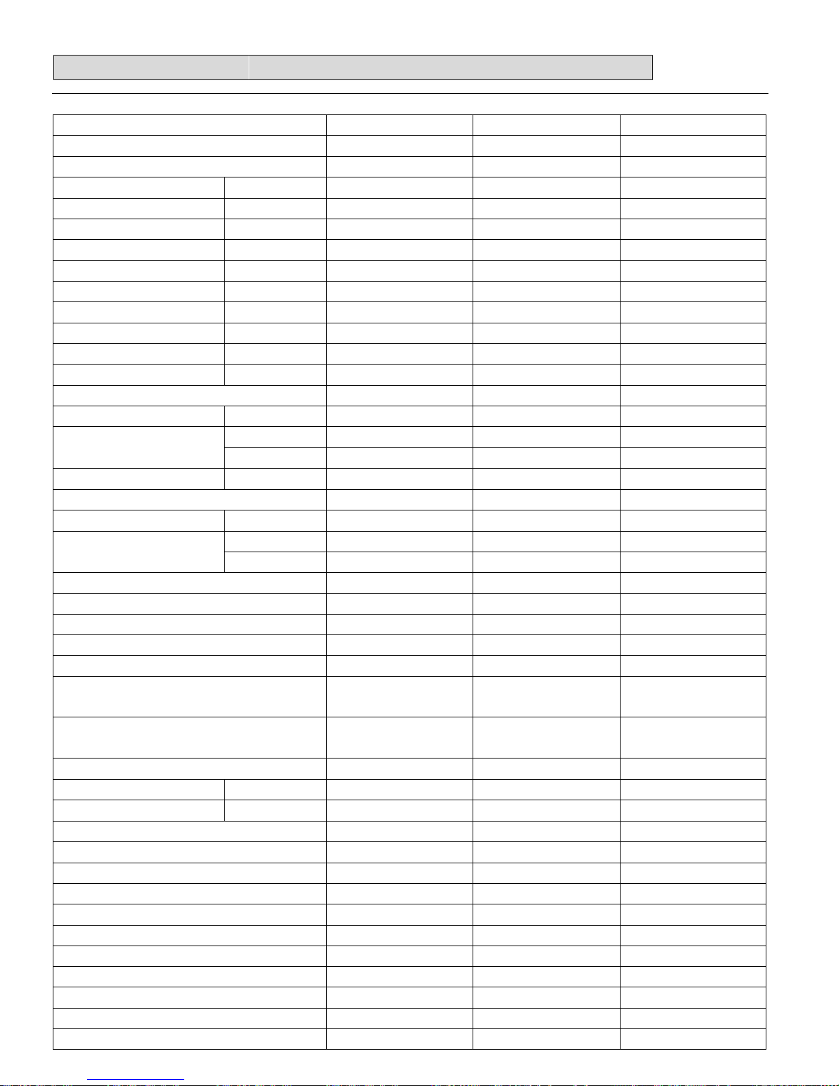
22.. SSPPEECCIIFFIICCAATTIIOONNSS
2-1. Unit specifications
Model No.
AS-09UR4SVNVG1
AS-12UR4SVNVG1 AS-12UR4SVGVG
Type T1, H/P, INVERTER T1, H/P, INVERTER T1, H/P, INVERTER
Ratings
Cooling Capacity W 2600(1200-3000) 3200(1200-3500) 3500(1400-3600)
Heating Capacity W 2900(1200-3500) 3400(1200-4000) 3550(1400-3800)
Rated Input-Cooling W 810(300-1450) 997(300-1550) 1090(430-1550)
Rated Input-Heating W 803(300-1500) 942(300-1600) 983(430-1600)
Moisture Removal L/H.r 0.9 1.5 1.5
Air Circulation m3/h 500 500 550
EER for Cooling W/W 3.21 3.21 3.21
COP for Heating W/W 3.61 3.61 3.61
Energy Class Cooling A A A
Energy Class Heatling A A A
Refrigerant R410A R410A R410A
Refrigerant charge volume
g 580 790 980
Indoor Unit Noise Level
High(dB (A)) 39 39 39
Low(dB (A)) 34 34 34
Outdoor Unit Noise Level dB (A) 52 52 53
Power Supply
Voltage, Frequency, Phase
V 220-240V~,50Hz,1P 220-240V~,50Hz,1P 220-240V~,50Hz,1P
Rated Current
Cooling (A) 3.8 4.5 4.8
Heating (A) 3.7 4.1 4.3
System
Compressor type Rotary Rotary Rotary
Compressor Model No. 39A23VPM&5JKE 39A23VPM&5JKE DA108M1C-10FZ2
Compressor MFG RECHI RECHI GMCC
Expansion Device Capillary Capillary Capillary
Evaporator
Copper tube and
Aluminum Fin
Copper tube and
Aluminum Fin
Copper tube and
Aluminum Fin
Condenser
Copper tube and
Aluminum Fin
Copper tube and
Aluminum Fin
Copper tube and
Aluminum Fin
Connecting Pipe Diameter
Liquid Pipe inch 1/4 1/4 1/4
Gas Pipe inch 3/8 3/8 3/8
Features
Display on Front Panel LED LED LED
LCD Wireless Remote Controller Yes Yes Yes
Removable and washable Panel Yes Yes Yes
Washable PP Filter Yes Yes Yes
24 Hours Timer Yes Yes Yes
3 Speed and Auto Indoor Fan Control Yes Yes Yes
Vertical Auto Swing Louver Yes Yes Yes
Manual Adjustable Horizontal Swing Louver
Yes Yes Yes
Sleep Operation Yes Yes Yes
Smart Function Yes Yes Yes

22.. SSPPEECCIIFFIICCAATTIIOONNSS
Dimmer Yes Yes Yes
Super Function Yes Yes Yes
Compressor Indicator Yes Yes Yes
Auto Restart Yes Yes Yes
Other
Net Dimensions
WxHxD (mm)
Indoor Unit 750×250×190 750×250×190 820X270X210
Outdoor Unit 715×482×240 715×482×240 715×482×240
Net Weight (Kg)
Indoor Unit 8 8 8.5
Outdoor Unit 26 28 27
Packing Dimensions
WxHxD (mm)
Indoor Unit 800×325×245 800×325×245 880x340x285
Outdoor Unit 830×530×315 830×530×315 830×530×315
Gross Weight (Kg)
Indoor Unit 9 9 9.5
Outdoor Unit 28 30 29
Loading Capacity (20'/40'/40'HC ) 148/298/350 148/298/350 130/262/307
Test Standard EN 14511 EN 14511 EN 14511
Approvals CE CE CE
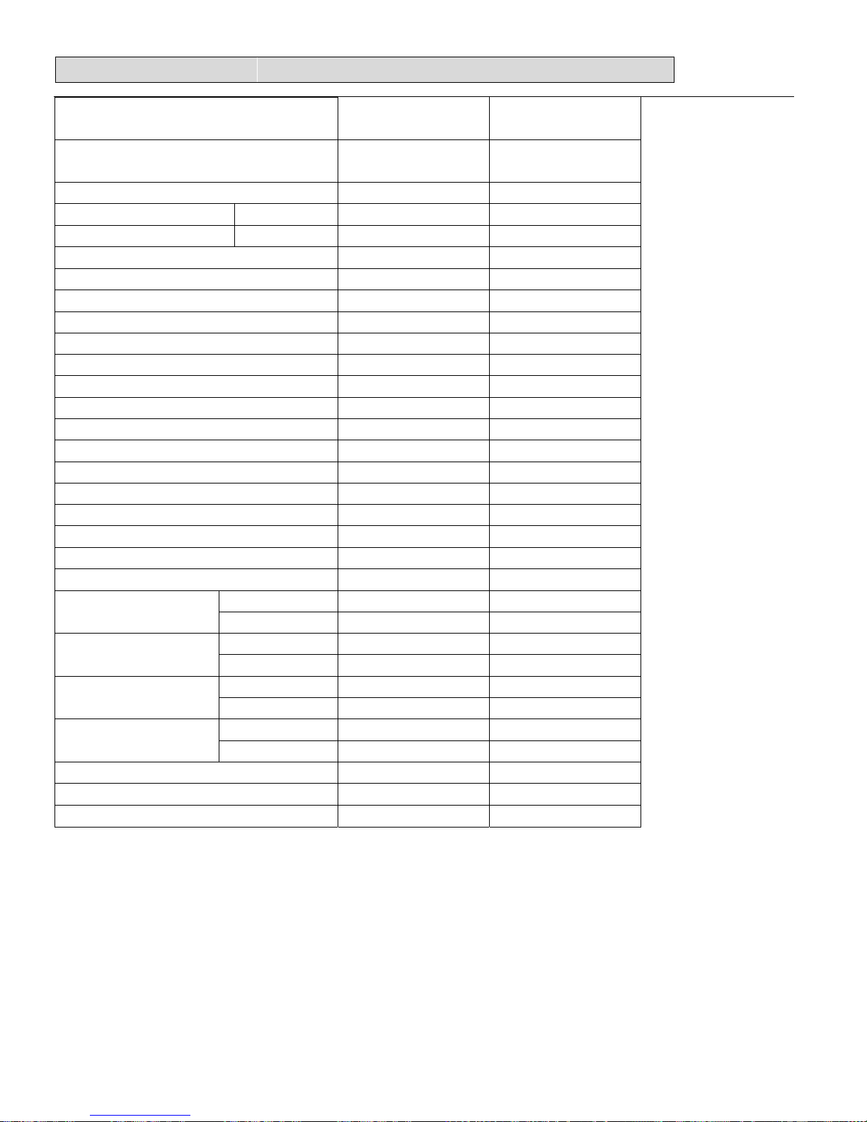
Model No.
AS-18UR4STVVG AS-24UR4SQJVG
Type T1, H/P, INVERTER T1, H/P, INVERTER
Ratings
Cooling Capacity W 5275(1817-5862) 7034(2198~7913)
Heating Capacity W 5569(1758-6741) 8206(2198~8792)
Rated Input-Cooling W 1550(480-2400) 2190(1400~3100)
Rated Input-Heating W 1540(480-2500) 2400(1400~3400)
Moisture Removal L/H.r 2.0 2.4
Air Circulation m3/h 900 950
EER for Cooling W/W 3.4 3.21
COP for Heating W/W 3.61 3.42
Energy Class Cooling A A
Energy Class Heatling A B
Refrigerant R410A R410A
Refrigerant charge volume
g 1700 1950
Indoor Unit Noise Level
High(dB (A)) 47 48
Low(dB (A)) 42 43
Outdoor Unit Noise Level dB (A) 56 58
Power Supply
Voltage, Frequency, Phase
V 220-240V~,50Hz,1P 220-240V~,50Hz,1P
Rated Current
Cooling (A) 7.6 10
Heating (A) 7.4 10.5
System
Compressor type Rotary Rotary
Compressor Model No. DA130S1C-20FZ C-7RVN153H0W
Compressor MFG GMCC SANYO
Expansion Device Capillary Capillary
22.. SSPPEECCIIFFIICCAATTIIOONNSS
Evaporator
Copper tube and
Aluminum Fin
Copper tube and
Aluminum Fin
Condenser
Copper tube and
Aluminum Fin
Copper tube and
Aluminum Fin
Connecting Pipe Diameter
Liquid Pipe inch 1/4 3/8
Gas Pipe inch 1/2 5/8
Features
Display on Front Panel LED LED
LCD Wireless Remote Controller Yes Yes
Removable and washable Panel Yes Yes
Washable PP Filter Yes Yes
24 Hours Timer Yes Yes
3 Speed and Auto Indoor Fan Control Yes Yes
Vertical Auto Swing Louver Yes Yes
Manual Adjustable Horizontal Swing Louver
Yes Yes
Sleep Operation Yes Yes
Smart Function Yes Yes
Dimmer Yes Yes
Super Function Yes Yes
Compressor Indicator Yes Yes
Auto Restart Yes Yes
Other
Net Dimensions
WxHxD (mm)
Indoor Unit 920x313x226 1035×313×220
Outdoor Unit 830x637x285 832×702×312
Net Weight (Kg)
Indoor Unit 11 13
Outdoor Unit 45 56
Packing Dimensions
WxHxD (mm)
Indoor Unit 1010x380x300 1130×390×310
Outdoor Unit 980×680×400 980x770x420
Gross Weight (Kg)
Indoor Unit 14 16
Outdoor Unit 49 60
Loading Capacity (20'/40'/40'HC ) 79/162/180 66/135/150
Test Standard EN 14511 EN 14511
Approvals CE CE

33.. IINNSSTTAALLLLAATTIIOON
N
1、How to choose an air conditioner:
a. Choice for reference: 150-170W/㎡ for average rooms;
b. Choice for reference: 160-200W/㎡ for small size offices;
c. Choice for reference: 220-350W/㎡ for restaurants;
d. Choice for reference: 200-300W/㎡ for entertaining venues;
e. Choice for reference: 220-280W/㎡ for the top floor.
Note:1W = 3.412btu.
2、Indoor Unit:
For indoor unit installation, the distance between its top and the ceiling shall
not be less than 10 cm -20 cm, and the distance from the ground should be
between 2m to 2.6m. Also the wallboard must be smooth and straight, with its
supporting force of not less than 60 kg.
The location for installing the indoor unit shall be far away from heat source,
the space between it and the door or window should exceed 0.6m
3、Outdoor Unit:
The air conditioner outdoor unit should not occupy public sidewalks, the
distance between the mounting bracket installed along the road (on condition that
the mounting bracket does not affect the public access, it can be installed
horizontally) and the ground must exceed 2.5m. Also we shall remember that: a.
the air flow must run freely . b. we should protect famous ancient buildings during
installation. c. the installation does not affect the traffic.
The distance between air outlet of outdoor unit and the opposite object should
be more than 1 meter, otherwise the machine would stop running because of
overload by heat yield failure.
If the outdoor unit was opposite the resident's door or window, you should
install the machine as far as possible away from the adjacent doors windows and
plants, and the distance shall not be less than the following values: for the r ated
cooling capacity not more than 4.5KW, the distance should be 3m.; for the rated
cooling capacity more than 4.5KW, the distance should be 4m.
It should remember to avoid installing at places where the natural
environment is harsh, such as heavy fumes and wind, direct sunlight or
high-temperature and heat, together with the place where children easily reach.
4. The Unit:
When installing the air conditioner, the outdoor unit should be below the
indoor unit so as to facilitate circle of refrigerant and refrigeration oil .(1)The
height difference between wall mounted indoor unit and the outdoor unit is
generally not more than 5 meters. (2)The connection pipe can't exceed 5 meters,
and the longest is 15 meters. When the length exceeds 5 meters, 20g fluoride is
required to be added for each exceeding 1m.
44.. RREEFFRRIIGGEERRAANNTT FFLLOOWW DDIIAAGGRRAAMM
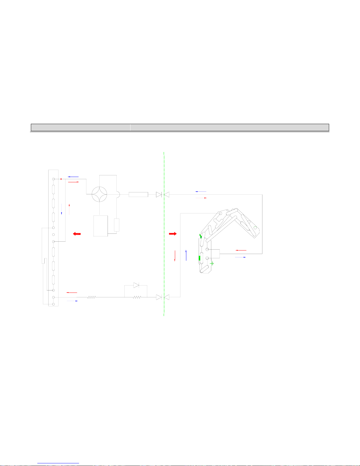
4-1. Refrigerant flow diagram :
CAPILLARY
COMPRESSOR
CHECK VALVE ASS'Y
CAPILLARY
CONDENSER
EVAPORATOR
OUTDOOR
INDOOR
出2
44.. RREEFFRRIIGGEERRAANNTT FFLLOOWW DDIIAAGGRRAAMM
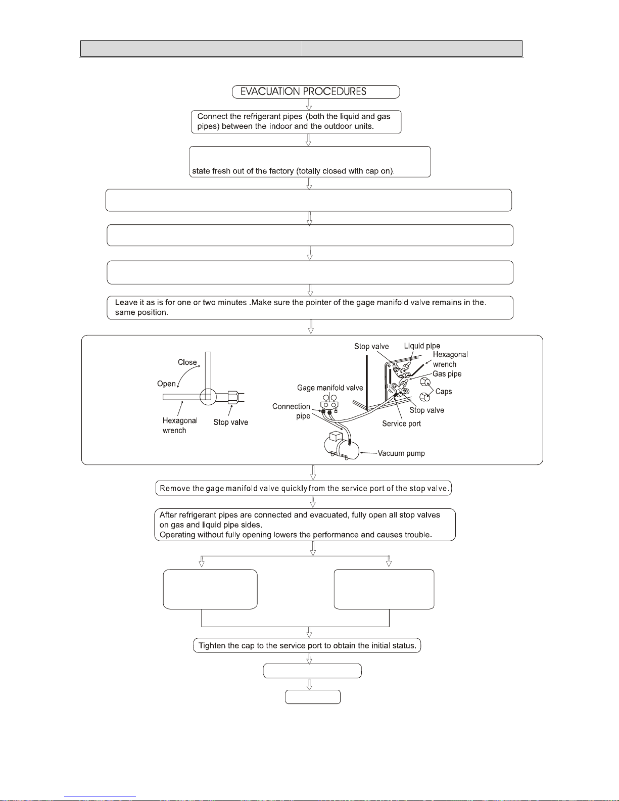
4-2. Evacuation procedures:
Remove the service port cap of the stop valve on the side of the
outdoor unit gas pipe. (The stop valve will not work in its initial
Connect the gage manifold valve and the vacuum pump to the service port of the stop valve on the gas pipe
side of the outdoor unit.
Run the vacuum pump for more than 15 minutes and at this time confirm that the pressure gage indicates
-0.1 Mpa (-76 cmHg).
Check the vacuum with the gage manifold valve, then close the gage manifold valve, and stop the
vacuum pump.
Pipe length
5m and 7m maximum
No gas charge is
needed.
Pipe length
exceeding 5m and 7m
Charge the prescribed
amount of gas.
Retighten the cap.
Leak test
55.. EELLEECCTTRRIICCAALL DDAATTAA
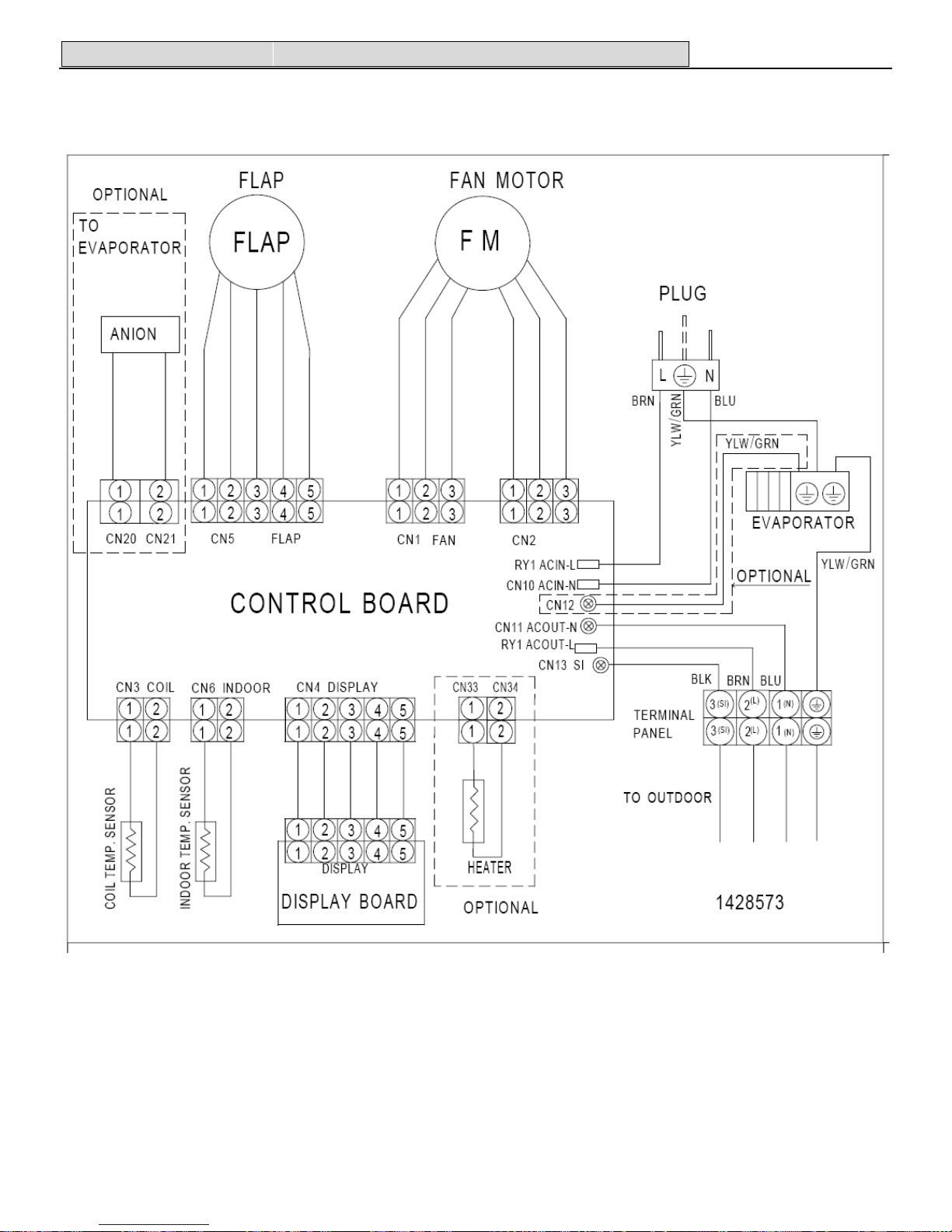
5-1.Electrical wiring diagrams
INDOOR:
(1)AS-09UR4SVNVG1、AS-12UR4SVNVG1(indoor):
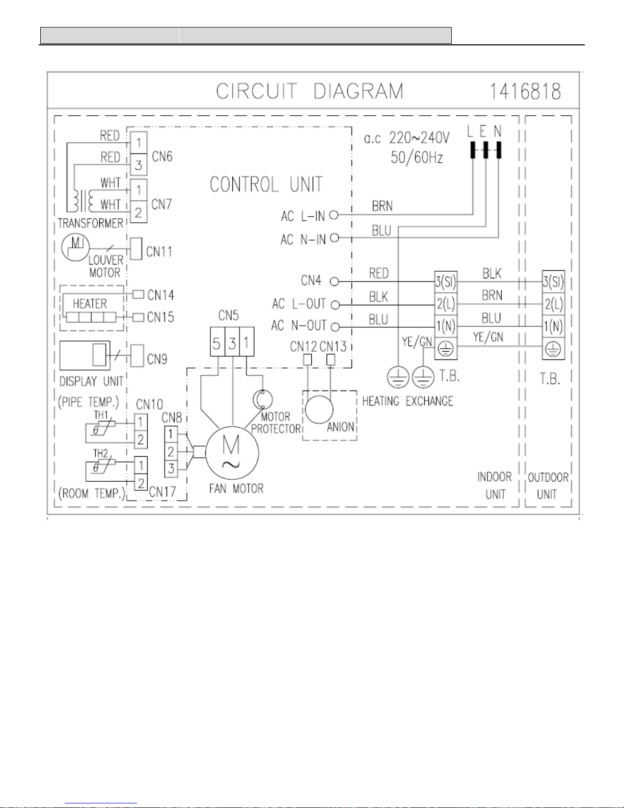
55.. EELLEECCTTRRIICCAALL DDAATTAA
(2)AS-12UR4SVGVG(indoor):
 Loading...