

Hisense AS-09UR4SGNPQ Service Manual

第 1/51页
SERVICE MANUAL
AS-09UR4SGNPQ
Hisense Corporation

第 2/51页
Table of contents
Page
1.OPERATING RANGE …………………………………………………………………………….….1
2.SPECIFICATION………………………………………………………………………………….… 2
2-1 Unit specifications ………………………………………………………………
2-2 Major component specifications ………………………………………………
2-3 Other component specifications ………………………………………………
3.OUTLINES AND DIMENSIONS…………………………………………………………..…..…… 6
3-1 INDOOR ………………………………………………………………………
3-2 OUTDOOR ……………………………………………………………………..
4.REFRIGERANT FLOW DIAGRAM ………………………………………………………..………8
4-1 Refrigerant flow diagram ……………………………………………………………………..
4-2 Evacuation procedures ……………………………………………………………………..
4-3 Evacuation direction ……………………………………………………………………..
5.ELECTRICAL DATA ………………………………………………………………………………..11
5-1 Electric wiring diagrams ……………………………………………………………………..
5-2 Electric control ……………………………………………………………………..
5-3 Sensor parameter ……………………………………………………………………..
6.CONTROL MODE 16 6-1 control mode …………………………………………………….....18
7.TROUBLESHOOTING………………………………………………………………………….… 26
7-1 Error codes ………………………………………………………………………….
7-2 Service flow chart ……………………………………………………………………
8.CHECKING COMPONENTS……………………………………………………………………. 32
8-1 Check refrigerant system ……………………………………………………………………
8-2 Check parts unit ……………………………………………………………………
9.DISASSEMBLY INSTRUCTIONS ………………………………………………………………..38
9-1 Indoor ……………………………………………………………………
9-2 Outdoor ……………………………………………………………………
10.PARTS LIST ………………………………………………………………………………….…45
10-1 Indoor ……………………………………………………………………
10-2 Outdoor ……………………………………………………………………

22.. SSPPEECCIIFFIICCAATTIIOONNSS
第 3/51页
2-3-5. OVERLOAD PROTECTION
AASS--0099UURR44SSGGN
NPQ
ELECTRIC
PERFORMANCE
Model INT01L-4639/CS-74
Reset temperature( )℃ 90±5℃
Trip temperature( )℃ 120±4℃
PARAMETER
22.. SSPPEECCIIFFIICCAATTIIOONNSS
第 4/51页
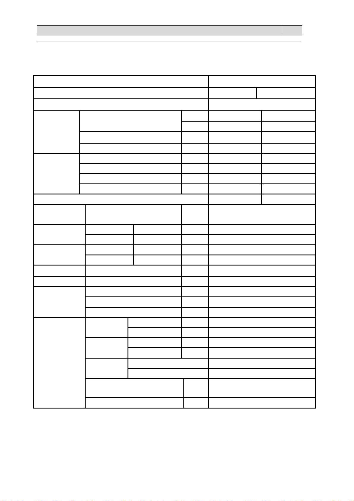
2-1. Unit specifications
Model AS-09UR4SGNPQ
Function Cooling Heating
Power supply a.c 220V~230V/50Hz
AASS--0099UURR44SSGGN
NPQ
Capacity
Electrical data
EER/COP 3.42 3.64
MAX.operating
pressure
Net size
Package size
Net weight Indoor unit / Outdoor unit kg 9.5/34.0
Gross weight Indoor unit / Outdoor unit kg 11.5/38.5
Dehumidification l /h 1.0
Air flow m
Rated current A 3.6 4.5
MAX. current A 8.0 10.0
Rated input kW 0.76 0.88
MAX. input kW 1.50 1.85
High MP 4.15
Indoor unit
Outdoor unit
Indoor unit
Outdoor unit
L×W×H
L×W×H
L×W×H
L×W×H
BTU 9000 12000 Capacity
kW 2.6 3.2
—-
3
/h 480 530
cm
cm
cm
cm
75×19×25
80×26×57
84×27×31
95×37×65
Refrigerant
piping
Special
remarks
NOTE :Test conditions:
Cooling : Indoor: DB27℃/ WB19℃ Outdoor: DB35℃/ WB24℃
Heating: Indoor: DB20℃/ WB15℃ Outdoor: DB7℃/ WB 6℃
Liquid pipe mm 6.35
Gas pipe mm 9.52
Connection method Flared
Indoor unit dB 40 Sound level
(Hi)
(Hi)
regulator
Refrigerant filling
capacity(R410A)
Throttle mode CAPILLARY
Outdoor unit dB 52
Indoor unit rpm 800/1000/1250 Fan speed
Outdoor unit rpm 540/620/800
Indoor unit 3 Fan speed
Outdoor unit 1
kg 0.72
22.. SSPPEECCIIFFIICCAATTIIOONNSS
第 5/51页
AASS--0099UURR44SSGGN
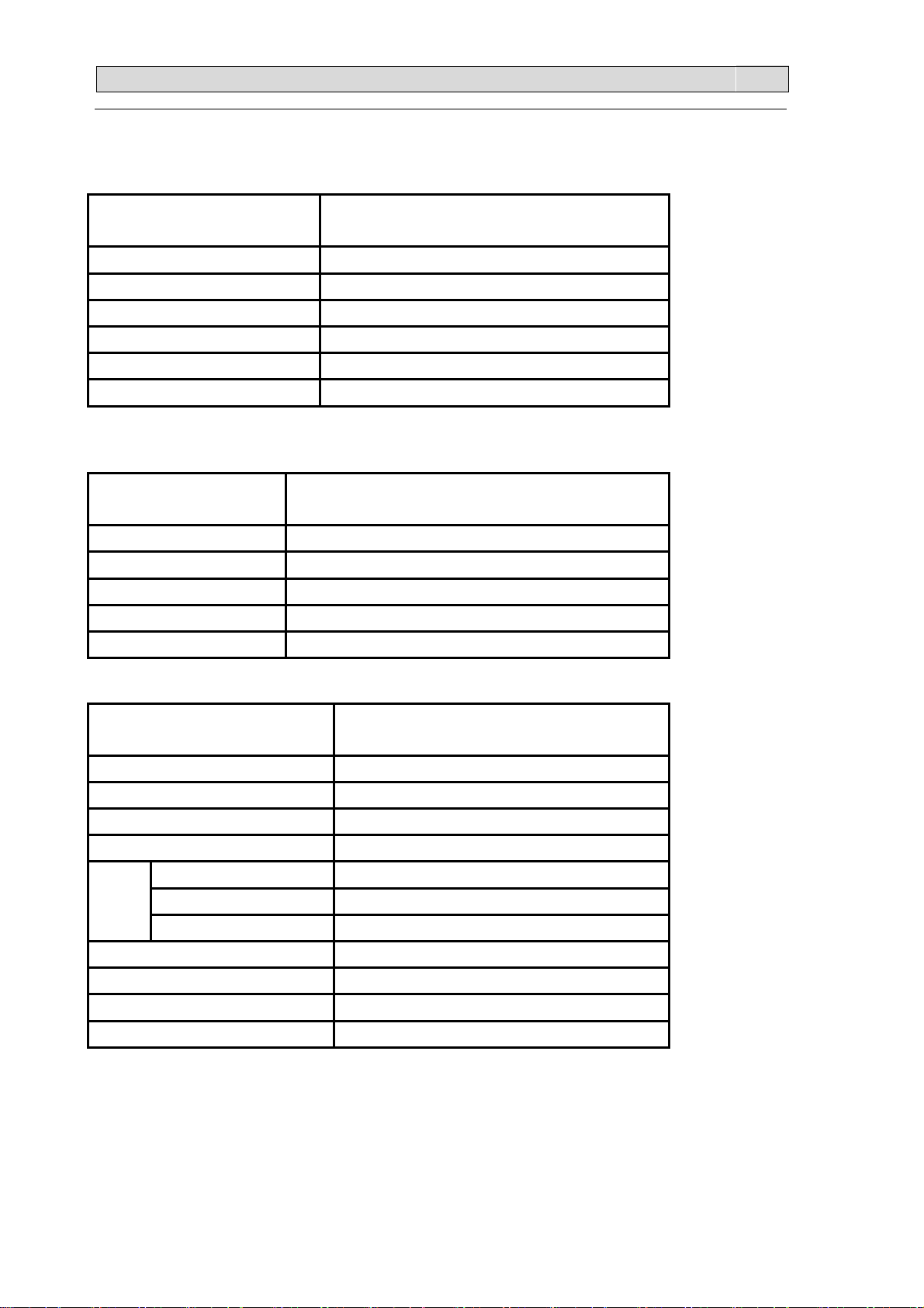
2-2. Major component specifications
2-2-1.INDOOR FAN MOTOR
ELECTRIC PERFORMANCE PARAMETER
Motor model YYW16-4-532
Rated power source 220V 50Hz
Phases/Poles 1/4
Rated load output(W) 16
Rated speed(r/min) -Ambient temperature( )℃
2-2-2 OUTDOOR FAN MOTOR
ELECTRIC
PERFORMANCE
Motor model YDK29-6I
Rated power source 220V 50Hz
Phases /Poles 1/6
Rated load output(W) 40
Ambient temperature( )℃
2-2-3. COMPRESSOR
ELECTRIC PERFORMANCE PARAMETER
Compressor model C-1RVN68HOE
Compressor type Rotary
Rated power 675W
Current (A) 4.75
Motor
Motor type DC brushless motor
-5℃~+43℃.
PARAMETER
-5℃~+43℃.
NPQ
Starting type DC Inverter
Winding resistance
Number of cylinder 1
Oil type FV50BX
Oil charge (cc) 350
Ambient temperature( )℃
0.71Ω(at 20 )℃
-5℃~+43 .℃

22.. SSPPEECCIIFFIICCAATTIIOONNSS
第 6/51页
AASS--0099UURR44SSGGN
2-3. Other component specifications
2-3-1. INDUCTANCE
ELECTRIC PERFORMANCE PARAMETER
Inductance model -
Rated power source -
Loop winding rated current - Rated
current(A)
inductance
Ambient temperature( )℃ -
2-3-2. INDUCTANCE(1205797,C)
ELECTRIC PERFORMANCE PARAMETER
Inductance model R2050HSB
(mH)
Filter winding rated current -
Loop winding rated inductance - Rated
Filter winding rated inductance -
NPQ
Rated power source 220V 50Hz
Rated current(A) 20
Rated inductance(mH) 5.2
Ambient temperature( )℃
2-3-3. FILTER(1336846,A)
ELECTRIC PERFORMANCE PARAMETER
Filter model RTLB-12T047-02JF
Rated current(A) 12
Rated power source AC 220V 50Hz
Filter frequency range 150K—30MHHz
Temperature range( )℃
2-3-4. STEPPER MOTOR
ELECTRIC PERFORMANCE PARAMETER
Stepper Motor model 24BYJ48-CP
-20℃~+70 .℃
-25℃~+85℃.
Voltage(DC) 12V
Number of phase 4
Drive mode 1-2phase excitation unipolar drive
Resistance per phase
Temperature range( )℃
300Ω±7%
-10℃~+40 .℃

22.. SSPPEECCIIFFIICCAATTIIOONNSS
第 7/51页
2-3-5. OVERLOAD PROTECTION
AASS--0099UURR44SSGGN
NPQ
ELECTRIC
PERFORMANCE
Model INT01L-4639/CS-74
Reset temperature( )℃ 90±5℃
Trip temperature( )℃ 120±4℃
PARAMETER
33.. OOUUTTLLIINNEESS AANNDD DDIIMMEENNSSIIOO
第 8/51页
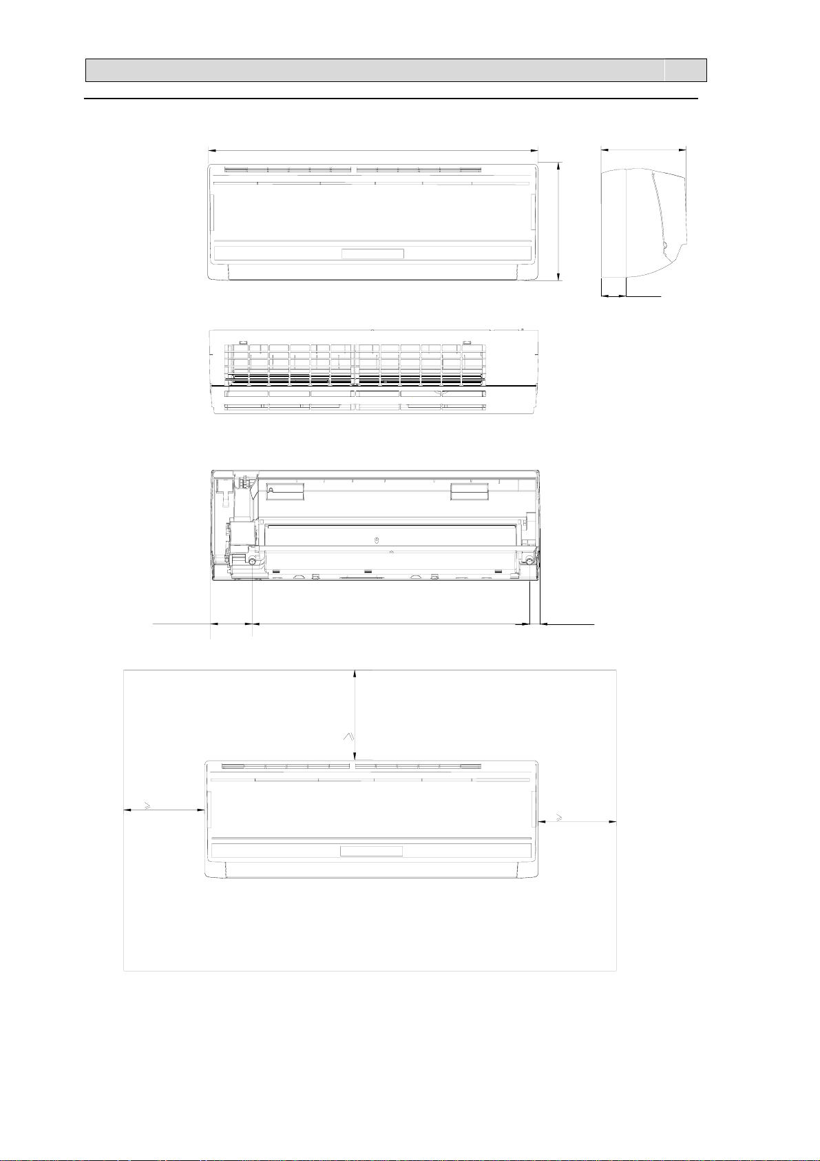
3-1. INDOOR
AASS--0099UURR44SSGGN
NPQ
750mm
190mm
250mm
65mm
94mm
50mm
23mm631mm
50mm
50mm
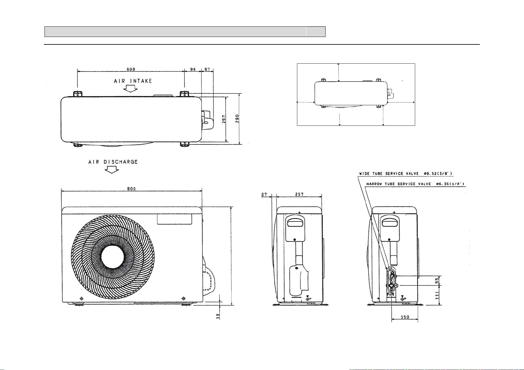
3-2.OUTDOOR
33.. OOUUTTLLIINNEESS AANNDD DDIIMMEENNSSIIOO
第 9/51页
AASS--0099UURR44SSGGN
NPQ
>10cm
>5cm
5
.
7
6
5
Outlet
>25cm
>40cm
44.. RREEFFRRIIGGEERRAANNTT FFLLOOWW DDIIAAGGRRAAM
第 10/51页
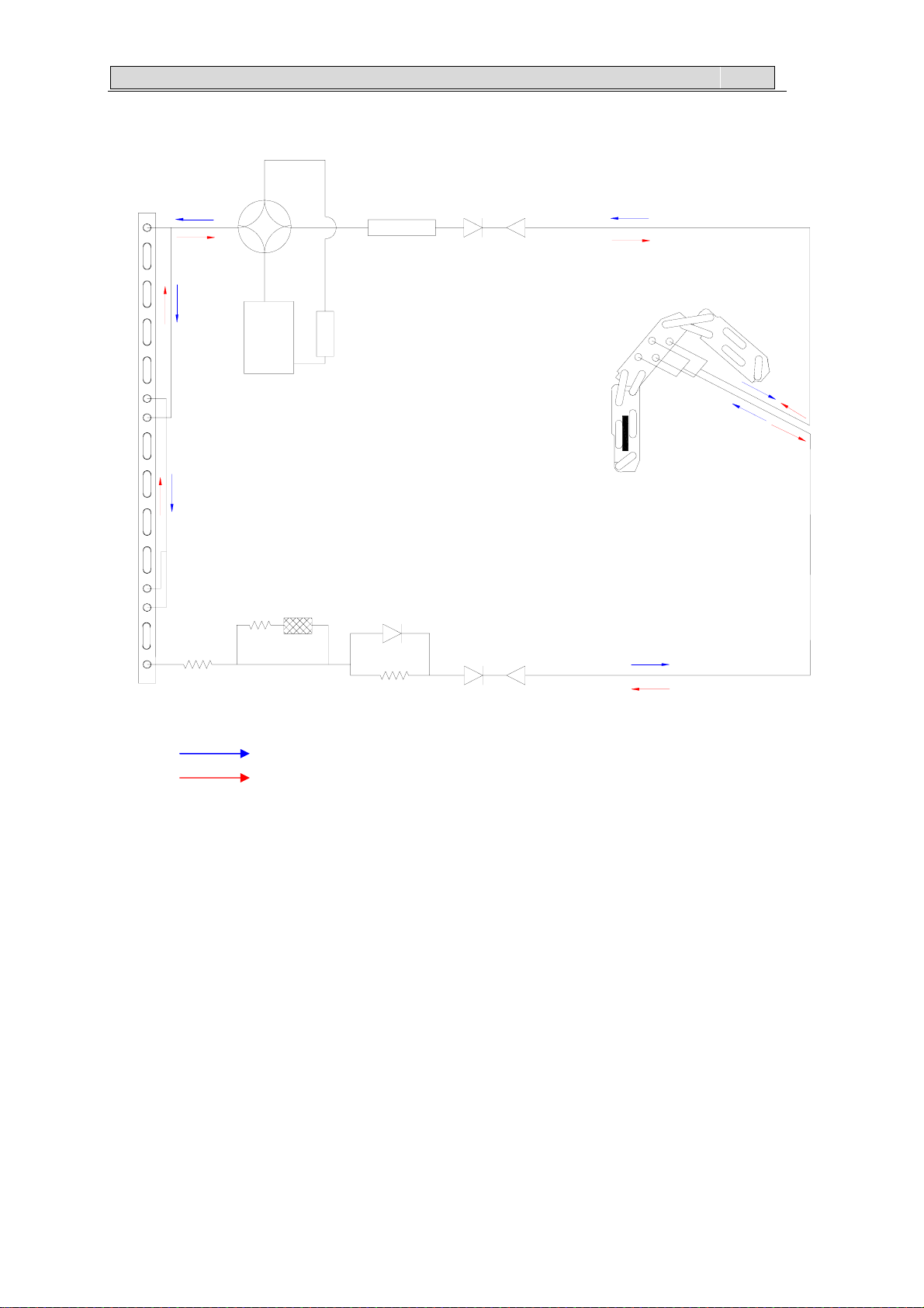
4-1. Refrigerant flow diagram :
COMPRESSOR
CONDENSER
M
AASS--0099UURR44SSGGN
INDOOROUTDOOR
EVAPORATOR
NPQ
desiccator
CAPILLARY
CHECK VALVE ASS'Y
Remark: COOLING CYCLE
Remark: HEATING CYCLE

44.. RREEFFRRIIGGEERRAANNTT FFLLOOWW DDIIAAGGRRAAM
第 11/51页
4-2. Evacuation procedures:
EVACUATION PROCEDURES
Connect the refriger ant pipes (both the l iquid and gas
pipes ) between the indoor and the outdoor units .
Remove the servi ce port cap of the stop valve on the side of the
outdoor unit gas pipe. (The stop valve will not work in its initial
state fresh out of the factory (totally closed with c ap on).
Connect the gage manifold v alve and the vacuum pump to the service port of the stop valve on
the gas pipe si de of the outdoor unit.
Run the vacuum pum p for m ore than 15 m inutes and at this ti m e c onfirm that the pres sure gage
indi cates -0.1 M pa (-76 cmHg).
Check the vacuum with the gage manifold valve, then c lose the gage manifold valve, and stop the
vacuum pum p.
Leave i t as is for one or two m inutes .Make s ure the pointer of the gage manifol d v alve r em ains
in the sam e pos ition.
M
AASS--0099UURR44SSGGN
NPQ
Stop valve
Close
Open
Hexagonal
wre nch
Remove the gage manifold valve quickly from the service port of the stop valve.
After refri gerant pipes are connec ted and ev acuated, fully open al l stop val ves
on gas and l iquid pipe s i des.
Operating without fully opening lowers the performance and c auses troubl e.
Stop valve
Pi pe l ength
7m maxi mum
No gas c harge is
needed.
Tighten the cap to the service port to obtai n the initial s tatus.
Gage manifold valve
Connection
pipe
Pi pe l ength
exc eeding 7m
Charge the pr escribed
amount of gas.
Liquid pipe
Hexagonal wrench
Gas pipe
Caps
Stop valve
Service port
Vacuum pump
Retighten the cap.
Leak tes t

44.. RREEFFRRIIGGEERRAANNTT FFLLOOWW DDIIAAGGRRAAM
第 12/51页
4-3. Evacuation direction:
MAX. REFRIGERANT PIPING LENGTH
M
AASS--0099UURR44SSGGN
NPQ
Refrigerant Piping
Models
AS 09UR4SGNZA
-
MAX. HEIGHT DIFFERENCE
Indoor
unit
Max. Height
difference 7m
Max. Length: m
A
Piping size (OD) : mm Length of connecting pipe : m
Gas
15 9 52
.
Refrigerant piping
Max. Length
A
Liquid Indoor unit
6.35
Outdoor unit
Outdoor unit
ADDITIONAL: REFRIGERANT CHARGE(R-410A: g)
Models
AS 09UR4SGNZA
-
Outdoor unit precharged
(up to 7m)
670
Refrigerant piping length
10m
0
45
Canculation :Xg=15g/m*(A-7)m
15m7m
120

55.. EELLEECCTTRRIICCAALL DDAATTAA
第 13/51页
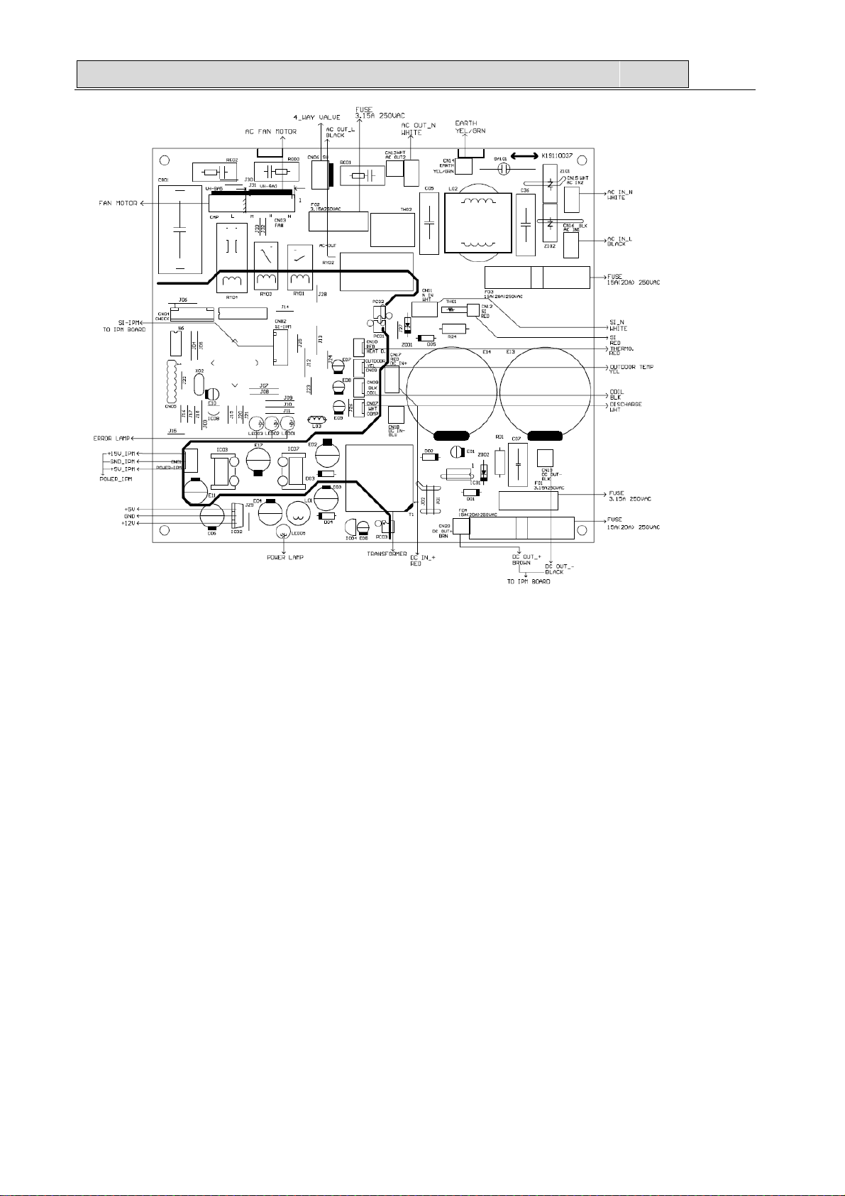
5-1.Electrical wiring diagrams
1.INDOOR
AASS--0099UURR44SSGGN
NPQ
2.OUTDOOR

55.. EELLEECCTTRRIICCAALL DDAATTAA
第 14/51页
AASS--0099UURR44SSGGN
NPQ
5-2. Electric control
1.Indoor control

55.. EELLEECCTTRRIICCAALL DDAATTAA
第 15/51页
AASS--0099UURR44SSGGN
NPQ
2.Outdoor control
55.. EELLEECCTTRRIICCAALL DDAATTAA
第 16/51页
AASS--0099UURR44SSGGN
NPQ
 Loading...