

Page 1
3ROLVK
Page 2

Page 3
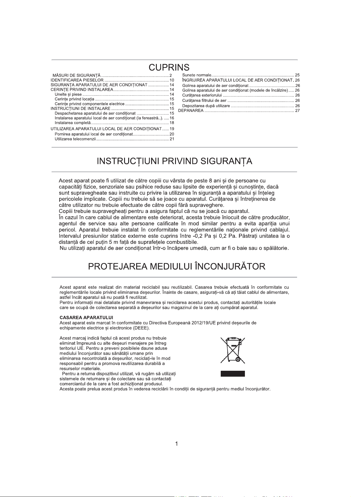
TABLE OF CONTENTS
.....
SAFETY PRECAUTIONS
IDENTIFICATION OF PARTS............................................
AIR CONDITIONER SAFETY.........................................................
INSTALLATION REQUIREMENTS................................................
Tools and Parts...........................................................................
Location Requirements...............................................................
Electrical Requirements..............................................................
INSTALLATION INSTRUCTIONS..................................................
Unpack the Air Conditioner.........................................................
Install Local Air Conditioner(on the window).....................
Complete Installation...................................................................
LOCAL
AIR CONDITIONER USE .
Starting Your Local Air Conditioner ........................................
the Remote Control..........................................................
Using
............................................
..
.....
.
.........................................
..
.
.
.
.
.
.....
.
.
Normal Sounds..........................................................................
2
LOCAL AIR CONDITIONER CARE.........................................
10
Draining the Air Conditioner.......................................................
14
Draining the Air Conditioner( Heating models)....... ...................
14
Cleaning the Outside..................................................................
14
Cleaning the Air Filter.................................................................
15
Storing After Use........................................................................
15
TROUBLESHOOTING..................................................................
15
15
16
18
2
2
.
.
.
.
.
.
.
.
SAFETY INSTRUCTIONS
This appliance can be used by children aged from 8 years and above and persons with
reduced physical, sensory or mental capabilities or lack of experience and knowledge if
they have been given supervision or instruction concerning use of the appliance in a
safe way and understand the hazards involved. Children shall not play with the
appliance. Cleaning and user maintenance shall not be made by children without
supervision.
Children should be supervised to ensure that they do not play with the appliance.
If the supply cord is damaged, it must be replaced by the manufacturer, its service agent
or similarly qualified persons in order to avoid a hazard.The appliance shall be installed
in accordance with national wiring regulations.The range of external static pressures is
-0.2Pa to 0.2Pa.Keep the unit 5m or more apart from combustible surfaces.
Do not operate your air conditioner in a wet room such as a bathroom or laundry room.
2
2
2
.
.
.
.
.
.
.
.
.
.
.
.
.
.
2
2
2
2
2
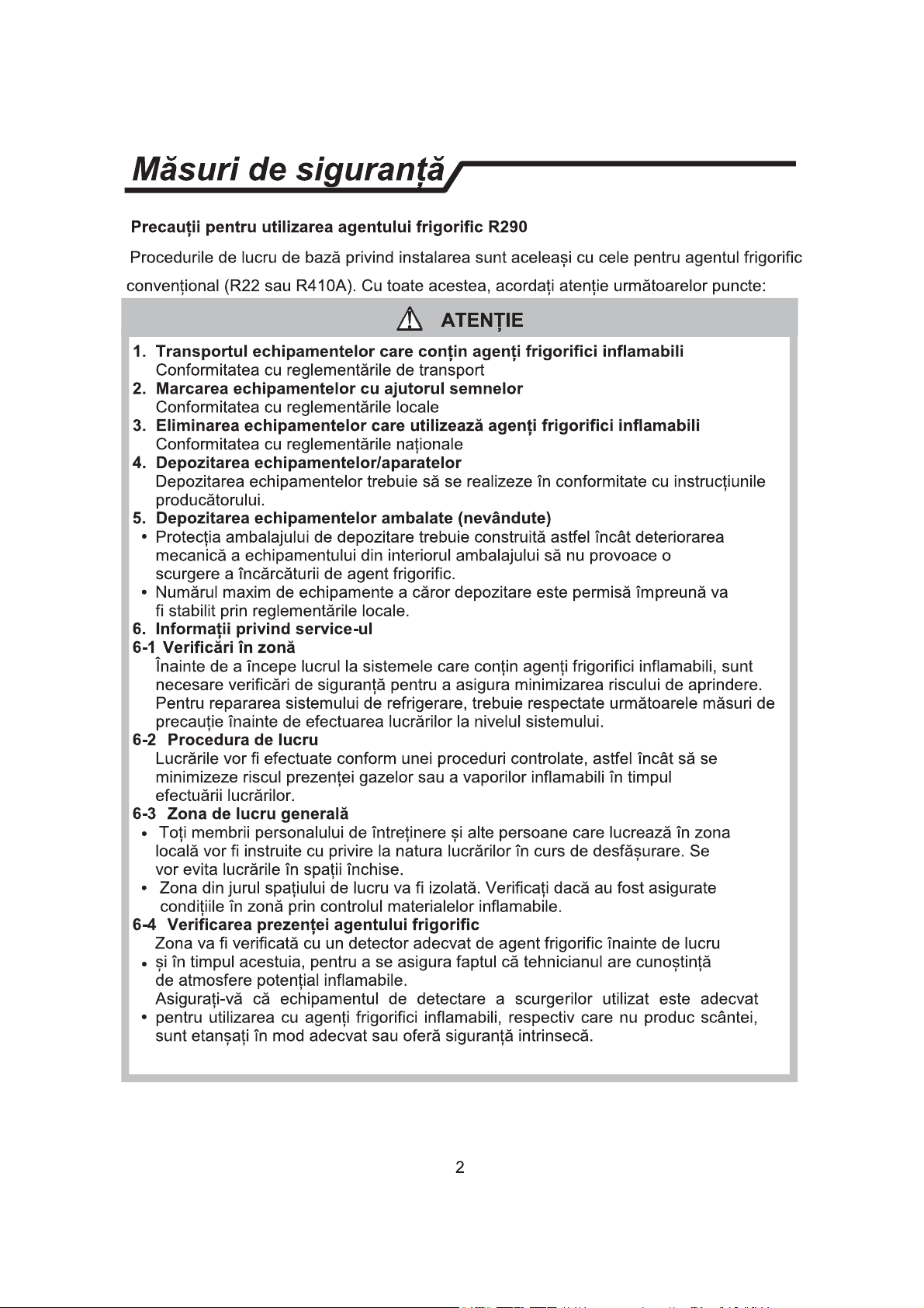
SAFEGUARDING THE ENVIRONMENT
This appliance is made of recyclable or re-usable material. Scrapping must be carried out in compliance
with local waste disposal regulations. Before scrapping it, make su re to cut off the mains co rd so that the
appliance cannot be re-used.
For more detailed information on handling and recycling this product, contact your local authorities
who deal with the separate collection of rubbish or the shop where you bought the appliance.
SCRAPPING OF APPLIANCE
This appliance is marked according to the European Directive 2012/19/EU, Waste Electrical and
Electronic Equipment (WEEE).
This marking indicates that this product should not be
disposed with other household wastes throughout
the EU. To prevent possible harm to the environment
or human health from uncontrolled waste disposal,
recycle it responsibly to promote the sustainable
reuse of material resources. To return your used device,
please use the return and collection systems or contact
the retailer where the product was purchased.
They can take this product for environmental safe recycling.
1
Page 4
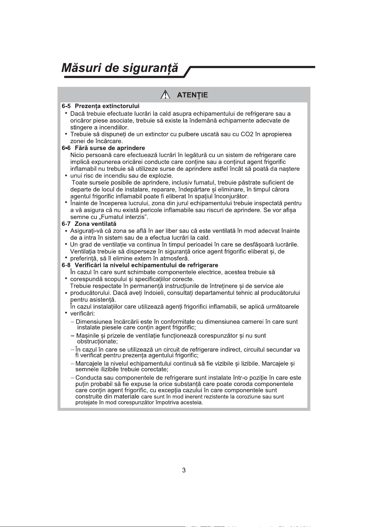
Safety precautions
Precautions for using R290 refrigerant
The basic installation work procedures are the same as the conventional refrigerant (R22 or R410A).
However, pay attention to the following points:
CAUTION
1. Transport of equipment containing flammable refrigerants
Compliance with the transport regulations
2. Marking of equipment using signs
Compliance with local regulations
3. Disposal of equipment using flammable refrigerants
Compliance with national regulations
4. Storage of equipment/appliances
The storage of equipment should be in accordance with the manufacturer's
instructions.
5. Storage of packed (unsold) equipment
Storage package protection should be constructed such that mechanical
damage to the equipment inside the package will not cause a leak of the
refrigerant charge.
The maximum number of pieces of equipment permitted to be stored together
will be determined by local regulations.
6. Information on servicing
6-1 Checks to the area
Prior to beginning work on systems containing flammable refrigerants, safety
checks are necessary to ensure that the risk of ignition is minimised. For repair
to the refrigerating system, the following precautions shall be complied with
prior to conducting work on the system.
6-2 Work procedure
Work shall be undertaken under a controlled procedure so as to minimise the
risk of flammable gas or vapour being present while the work is being
performed.
6-3 General work area
All maintenance staff and others working in the local area shall be instructed
on the nature of work being carried out. Work in confined spaces shall be
avoided.
The area around the workspace shall be sectioned off. Ensure that the
conditions within the area have been made safe by control of flammable
material.
6-4 Checking for presence of refrigerant
The area shall be checked with an appropriate refrigerant detector prior to and
during work, to ensure the technician is aware of potentially flammable
atmospheres.
Ensure that the leak detection equipment being used is suitable for use with
flammable refrigerants, i.e. non-sparking, adequately sealed or intrinsically
safe.
2
Page 5
Safety precautions
CAUTION
6-5 Presence of fire extinguisher
If any hot work is to be conducted on the refrigeration equipment or any
associated parts, appropriate fire extinguishing equipment shall be available
to hand.
Have a dry powder or CO2 fire extinguisher adjacent to the charging area.
6-6 No ignition sources
No person carrying out work in relation to a refrigeration system which involves
exposing any pipe work that contains or has contained flammable refrigerant
shall use any sources of ignition in such a manner that it may lead to the risk of
fire or explosion.
All possible ignition sources, including cigarette smoking, should be kept
sufficiently far away from the site of installation, repairing, removing and
disposal, during which flammable refrigerant can possibly be released to the
surrounding space.
Prior to work taking place, the area around the equipment is to be surveyed to
make sure that there are no flammable hazards or ignition risks. “No Smoking”
signs shall be displayed.
6-7 Ventilated area
Ensure that the area is in the open or that it is adequately ventilated before
breaking into the system or conducting any hot work.
A degree of ventilation shall continue during the period that the work is carried
out.
The ventilation should safely disperse any released refrigerant and preferably
expel it externally into the atmosphere.
6-8 Checks to the refrigeration equipment
Where electrical components are being changed, they shall be fit for the
purpose and to the correct specification.
At all times the manufacturer's maintenance and service guidelines shall be
followed. If in doubt consult the manufacturer's technical department for
assistance.
The following checks shall be applied to installations using flammable
refrigerants:
– The charge size is in accordance with the room size within which the
refrigerant containing parts are installed;
– The ventilation machinery and outlets are operating adequately and are not
obstructed;
– If an indirect refrigerating circuit is being used, the secondary circuit shall be
checked for the presence of refrigerant;
– Marking to the equipment continues to be visible and legible. Markings and
signs that are illegible shall be corrected;
– Refrigeration pipe or components are installed in a position where they are
unlikely to be exposed to any substance which may corrode refrigerant
containing components, unless the components are constructed of materials
3
Page 6
Safety precautions
CAUTION
which are inherently resistant to being corroded or are suitably protected
against being so corroded.
6-9 Checks to electrical devices
Repair and maintenance to electrical components shall include initial safety
checks and component inspection procedures.
If a fault exists that could compromise safety, then no electrical supply shall be
connected to the circuit until it is satisfactorily dealt with.
If the fault cannot be corrected immediately but it is necessary to continue
operation, an adequate temporary solution shall be used.
This shall be reported to the owner of the equipment so all parties are advised.
Initial safety checks shall include:
– That capacitors are discharged: this shall be done in a safe manner to avoid
possibility of sparking;
– That there no live electrical components and wiring are exposed while
charging, recovering or purging the system;
– That there is continuity of earth bonding.
7. Repairs to sealed components
During repairs to sealed components, all electrical supplies shall be
disconnected from the equipment being worked upon prior to any removal of
sealed covers, etc.
If it is absolutely necessary to have an electrical supply to equipment during
servicing, then a permanently operating form of leak detection shall be located
at the most critical point to warn of a potentially hazardous situation.
Particular attention shall be paid to the following to ensure that by working on
electrical components, the casing is not altered in such a way that the level of
protection is affected.
This shall include damage to cables, excessive number of connections,
terminals not made to original specification, damage to seals, incorrect fitting
of glands, etc.
Ensure that apparatus is mounted securely.
Ensure that seals or sealing materials have not degraded such that they no
longer serve the purpose of preventing the ingress of flammable atmospheres.
Replacement parts shall be in accordance with the manufacturer's
specifications.
NOTE:
The use of silicon sealant may inhibit the effectiveness of some types of
leak detection equipment. Intrinsically safe components do not have to be
isolated prior to working on them.
8. Repair to intrinsically safe components
Do not apply any permanent inductive or capacitance loads to the circuit
without ensuring that this will not exceed the permissible voltage and current
permitted for the equipment in use.
Intrinsically safe components are the only types that can be worked on while
4
Page 7
Safety precautions
CAUTION
live in the presence of a flammable atmosphere. The test apparatus shall be at
the correct rating.
Replace components only with parts specified by the manufacturer.
Other parts may result in the ignition of refrigerant in the atmosphere from a
leak.
9. Cabling
Check that cabling will not be subject to wear, corrosion, excessive pressure,
vibration, sharp edges or any other adverse environmental effects.
The check shall also take into account the effects of aging or continual
vibration from sources such as compressors or fans.
10.Detection of flammable refrigerants
Under no circumstances shall potential sources of ignition be used in the
searching for or detection of refrigerant leaks.
A halide torch (or any other detector using a naked flame) shall not be used.
11.Leak detection methods
The following leak detection methods are deemed acceptable for systems
containing flammable refrigerants:
– Electronic leak detectors shall be used to detect flammable refrigerants, but
the sensitivity may not be adequate, or may need re-calibration. (Detection
equipment shall be calibrated in a refrigerant-free area.)
– Ensure that the detector is not a potential source of ignition and is suitable
for the refrigerant used.
– Leak detection equipment shall be set at a percentage of the LFL of the
refrigerant and shall be calibrated to the refrigerant employed and the
appropriate percentage of gas (25 % maximum) is confirmed.
– Leak detection fluids are suitable for use with most refrigerants but the use
of detergents containing chlorine shall be avoided as the chlorine may react
with the refrigerant and corrode the copper pipe-work.
– If a leak is suspected, all naked flames shall be removed/ extinguished.
– If a leakage of refrigerant is found which requires brazing, all of the
refrigerant shall be recovered from the system, or isolated (by means of shut
off valves) in a part of the system remote from the leak.
– Oxygen free nitrogen (OFN) shall then be purged through the system both
before and during the brazing process.
12.Removal and evacuation
When breaking into the refrigerant circuit to make repairs – or for any other
purpose – conventional procedures shall be used.
However, it is important that best practice is followed since flammability is a
consideration.
The following procedure shall be adhered to:
– Remove refrigerant;
Purge the circuit with inert gas;
–
5
Page 8
Safety precautions
CAUTION
– Evacuate;
– Purge again with inert gas;
– Open the circuit by cutting or brazing.
The refrigerant charge shall be recovered into the correct recovery cylinders.
The system shall be “flushed” with OFN to render the unit safe.
This process may need to be repeated several times.
Compressed air or oxygen shall not be used for this task.
Flushing shall be achieved by breaking the vacuum in the system with OFN and
continuing to fill until the working pressure is achieved, then venting to
atmosphere, and finally pulling down to a vacuum.
This process shall be repeated until no refrigerant is within the system. When
the final OFN charge is used, the system shall be vented down to atmospheric
pressure to enable work to take place.
This operation is absolutely vital if brazing operations on the pipe-work are to
take place.
Ensure that the outlet for the vacuum pump is not close to any ignition sources
and there is ventilation available.
13.Charging procedures
In addition to conventional charging procedures, the following requirements
shall be followed:
– Ensure that contamination of different refrigerants does not occur when
using charging equipment.
– Hoses or lines shall be as short as possible to minimise the amount of
refrigerant contained in them.
– Cylinders shall be kept upright.
– Ensure that the refrigeration system is earthed prior to charging the system
with refrigerant.
– Label the system when charging is complete (if not already).
– Extreme care shall be taken not to overfill the refrigeration system.
Prior to recharging the system it shall be pressure tested with OFN.
The system shall be leak tested on completion of charging but prior to
commissioning.
A follow up leak test shall be carried out prior to leaving the site.
14.Decommissioning
Before carrying out this procedure, it is essential that the technician is
completely familiar with the equipment and all its detail.
It is recommended good practice that all refrigerants are recovered safely.
Prior to the task being carried out, an oil and refrigerant sample shall be taken in
case analysis is required prior to re-use of reclaimed refrigerant. It is essential
that electrical power is available before the task is commenced.
a) Become familiar with the equipment and its operation.
b) Isolate system electrically.
6
Page 9
Safety precautions
CAUTION
c) Before attempting the procedure ensure that:
– Mechanical handling equipment is available, if required, for handling
refrigerant cylinders;
– All personal protective equipment is available and being used correctly;
– The recovery process is supervised at all times by a competent person;
– Recovery equipment and cylinders conform to the appropriate standards.
d) Pump down refrigerant system, if possible.
e) If a vacuum is not possible, make a manifold so that refrigerant can be
removed from various parts of the system.
f) Make sure that cylinder is situated on the scales before recovery takes
place.
g) Start the recovery machine and operate in accordance with manufacturer's
instructions.
h) Do not overfill cylinders. (No more than 80 % volume liquid charge).
I ) Do not exceed the maximum working pressure of the cylinder, even
temporarily.
j ) When the cylinders have been filled correctly and the process completed,
make sure that the cylinders and the equipment are removed from site
promptly and all isolation valves on the equipment are closed off.
k) Recovered refrigerant shall not be charged into another refrigeration system
unless it has been cleaned and checked.
15.Labelling
Equipment shall be labelled stating that it has been de-commissioned and emptied
of refrigerant.
The label shall be dated and signed.
Ensure that there are labels on the equipment stating the equipment contains
flammable refrigerant.
16.Recovery
When removing refrigerant from a system, either for servicing or
decommissioning, it is recommended good practice that all refrigerants are
removed safely.
When transferring refrigerant into cylinders, ensure that only appropriate
refrigerant recovery cylinders are employed.
Ensure that the correct number of cylinders for holding the total system charge
is available.
All cylinders to be used are designated for the recovered refrigerant and
labelled for that refrigerant (i.e. special cylinders for the recovery of
refrigerant).
Cylinders shall be complete with pressure relief valve and associated shut-
off valves in good working order.
E
mpty recovery cylinders are evacuated and, if possible, cooled before
recovery occurs.
The recovery equipment shall be in good working order with a set of
7
Page 10
Safety precautions
CAUTION
instructions concerning the equipment that is at hand and shall be suitable for
the recovery of flammable refrigerants.
In addition, a set of calibrated weighing scales shall be available and in good
working order.
Hoses shall be complete with leak-free disconnect couplings and in good
condition.
Before using the recovery machine, check that it is in satisfactory working
order, has been properly maintained and that any associated electrical
components are sealed to prevent ignition in the event of a refrigerant release.
Consult manufacturer if in doubt.
The recovered refrigerant shall be returned to the refrigerant supplier in the
correct recovery cylinder, and the relevant Waste Transfer Note arranged.
Do not mix refrigerants in recovery units and especially not in cylinders.
If compressors or compressor oils are to be removed, ensure that they have
been evacuated to an acceptable level to make certain that flammable
refrigerant does not remain within the lubricant.
The evacuation process shall be carried out prior to returning the compressor
to the suppliers.
Only electric heating to the compressor body shall be employed to accelerate
this process.
When oil is drained from a system, it shall be carried out safely.
CAUTION
When moving or relocating the air conditioner, consult experienced service
technicians for disconnection and reinstallation of the unit.
Do not place any other electrical products or household belongings under
indoor unit or outdoor unit. Condensation dripping from the unit might get them
wet, and may cause damage or malfunction of your property.
Do not use means to accelerate the defrosting process or to clean, other than
those recommended by the manufacturer.
The appliance shall be stored in a room without continuously operating ignition
sources(for example, open flames, an operating gas appliance or an operating
electric heater).
Do not pierce or burn.
Be aware that refrigerants may not contain an odor.
To keep ventilation openings clear of obstruction.
The appliance shall be stored in a well-ventilated area where the room size
corresponds to the room area as specified for operation.
The appliance shall be stored in a room without continuously operating open
flames (for example an operating gas appliance) and ignition sources (for
example an operating electric heater).
The appliance shall be stored so as to prevent mechanical damage from
occurring.
8
Page 11
Safety precautions
WARNING
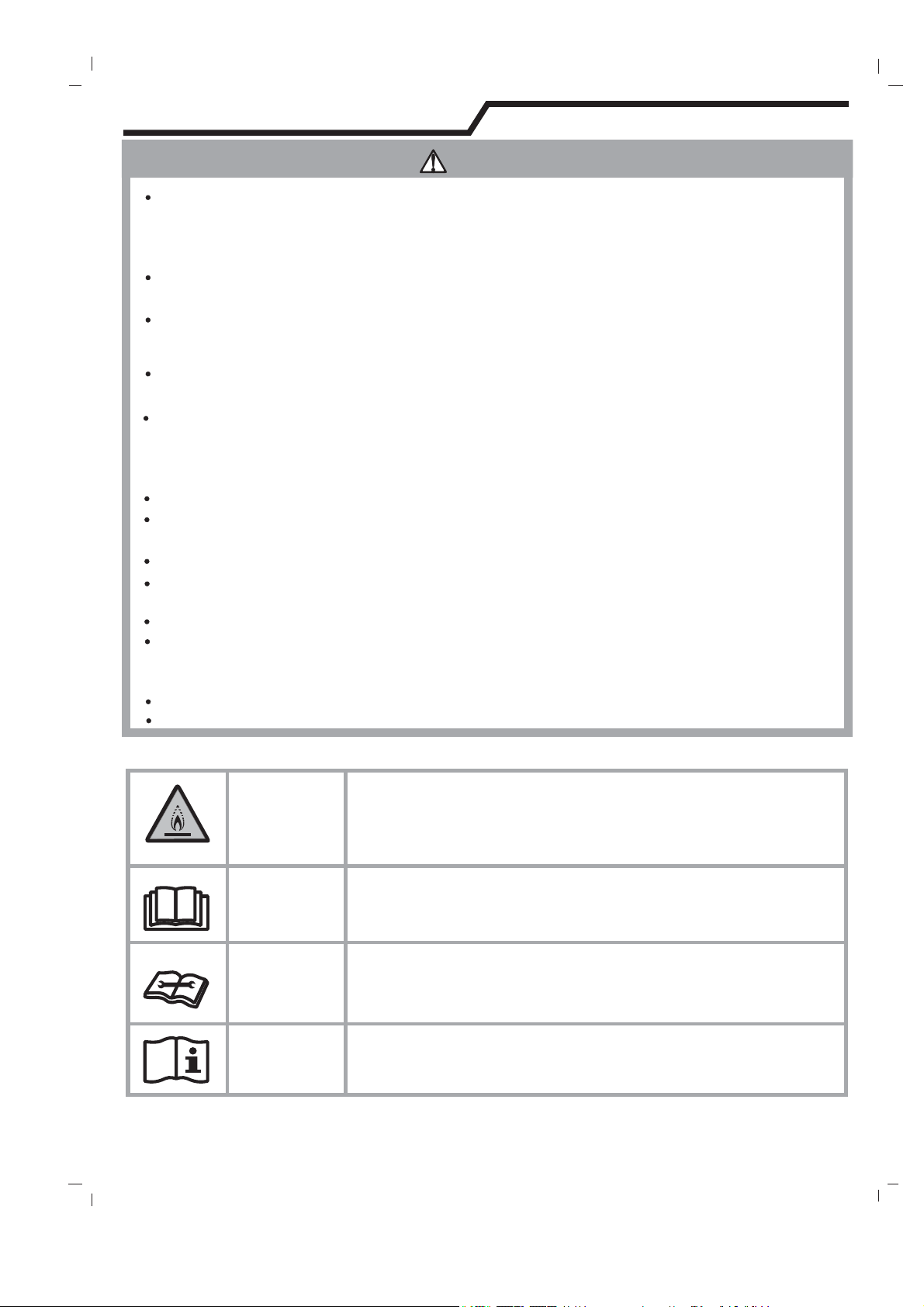
This symbol shows that this appliance uses a flammable
refrigerant.
If the refrigerant is leaked and exposed to an external
CAUTION
This symbol shows that the operation manual should be
read carefully.
CAUTION
This symbol shows that a service personnel should be
handling this equipment with reference to the
installation manual.
CAUTION
This symbol shows that information is available such as
the operating manual or installation manual.
CAUTION
Any person who is involved with working on or breaking into a refrigerant circuit
should hold a current valid certificate from an industry-accredited assessment
authority, which authorises their competence to handle refrigerants safely in
accordance with an industry recognised assessment specification.
Servicing shall only be performed as recommended by the equipment
manufacturer.
Maintenance and repair requiring the assistance of other skilled personnel
shall be carried out under the supervision of the person competent in the use of
flammable refrigerants.
Do not use means to accelerate the defrosting process or to clean, other than
those recommended by the manufacturer.
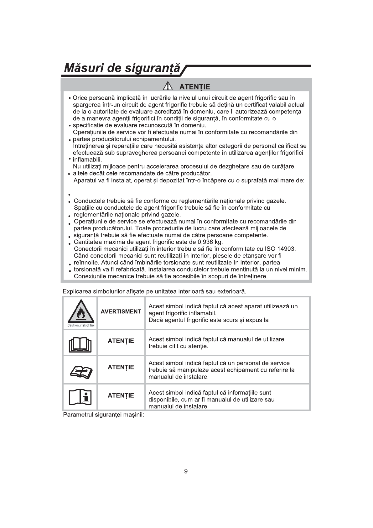
Appliance shall be installed, operated and stored in a room with a floor area
ODUJHUWKDQ$3&*16P, $3+*16P
$3&*46P, $3+*46P
The pipe-work shall be complianced with national gas regulations.
Spaces where refrigerant pipes shall be compliance with national gas
regulations.
Servicing shall be performed only as recommended by the manufacturer.
All working procedure that affects safety means shall only be carried by
competent persons.
The maximum refrigerant charge amount is 0.936 kg.
Mechanical connectors used indoors shall comply with ISO 14903. When
mechanical connectors are reused indoors, sealing parts shall be renewed.
When flared joints are reused indoors, the flare part shall be re-fabricated.
The installation of pipe-work shall be kept to a minimum.
Mechanical connections shall be accessible for maintenance purposes.
Explanation of symbols displayed on the indoor unit or outdoor unit.
Fuse parameter of the machine:
$3&*167$9, $3+*167$9
$3&*467$9$3+*467$9
9
Page 12
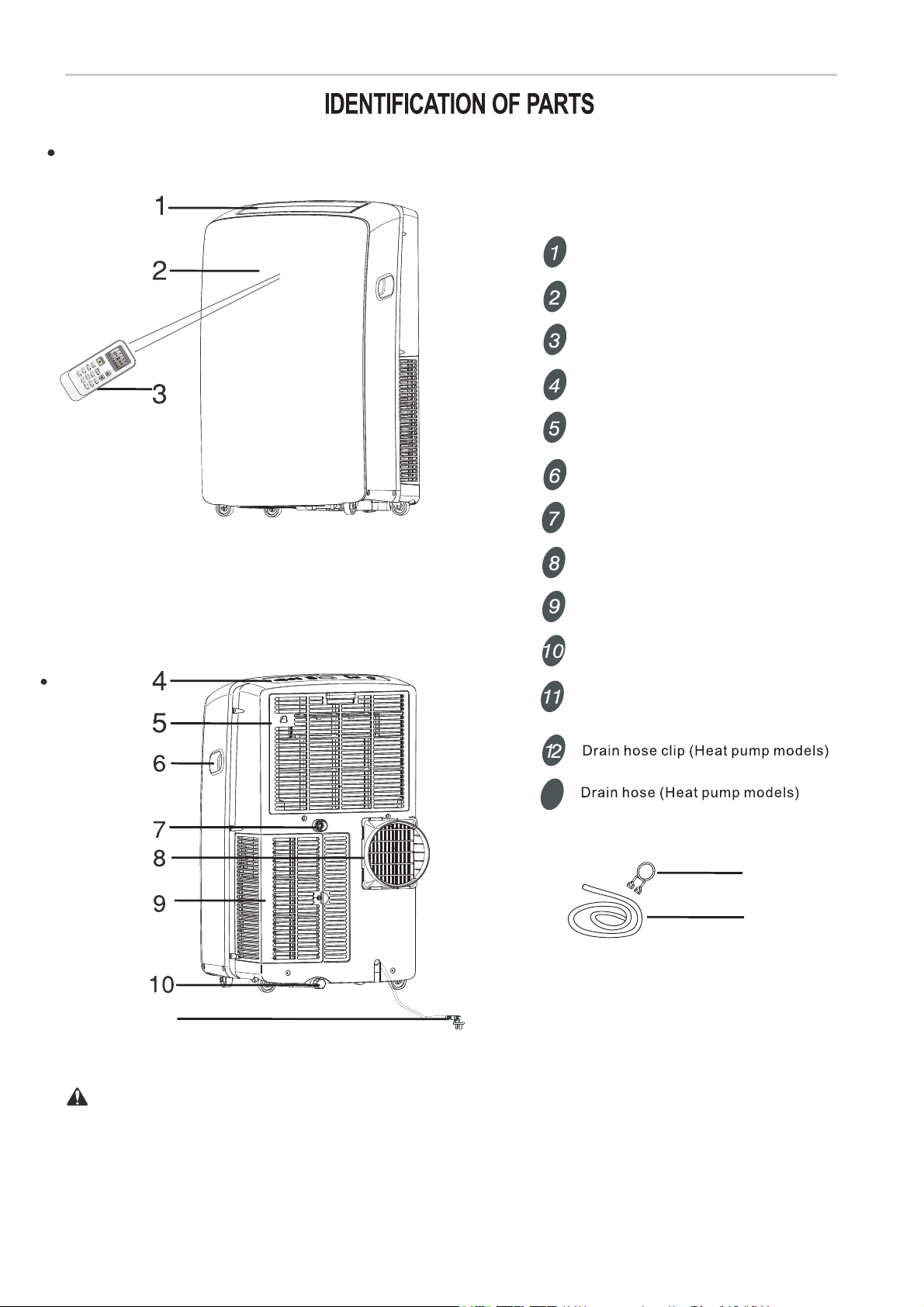
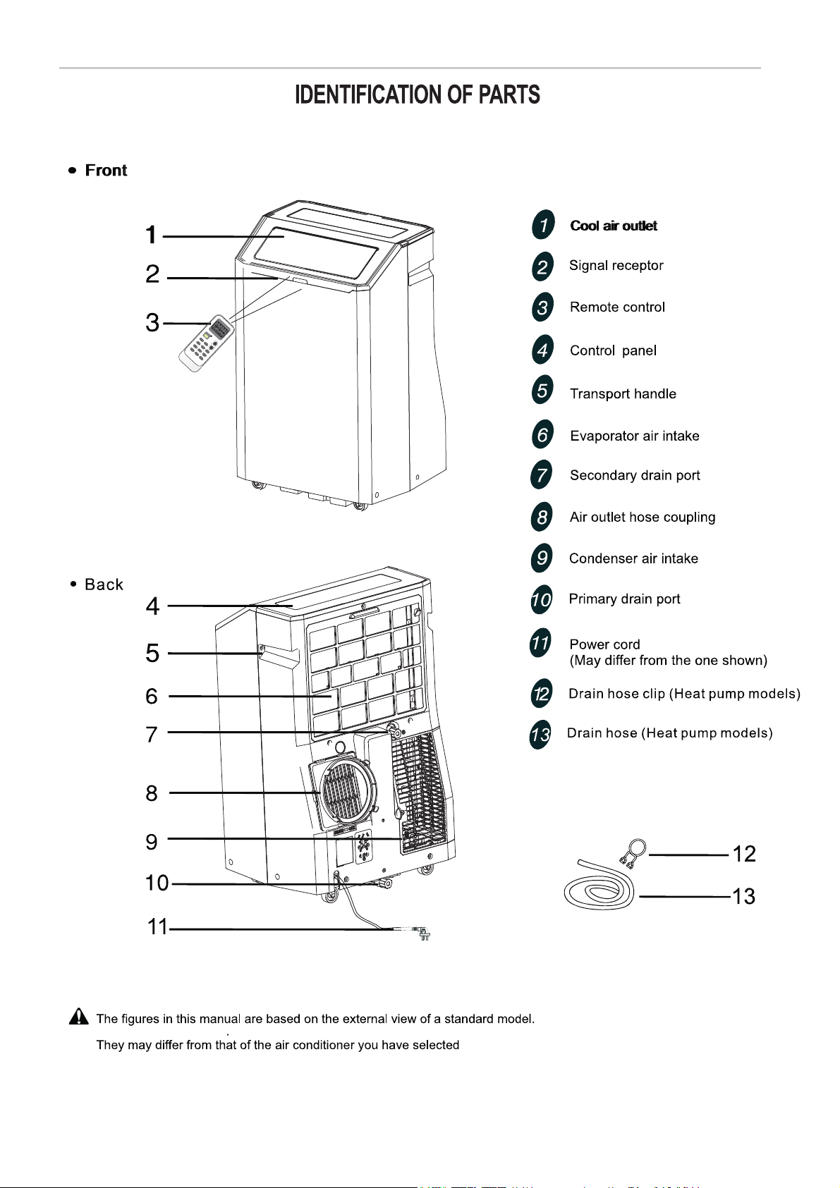
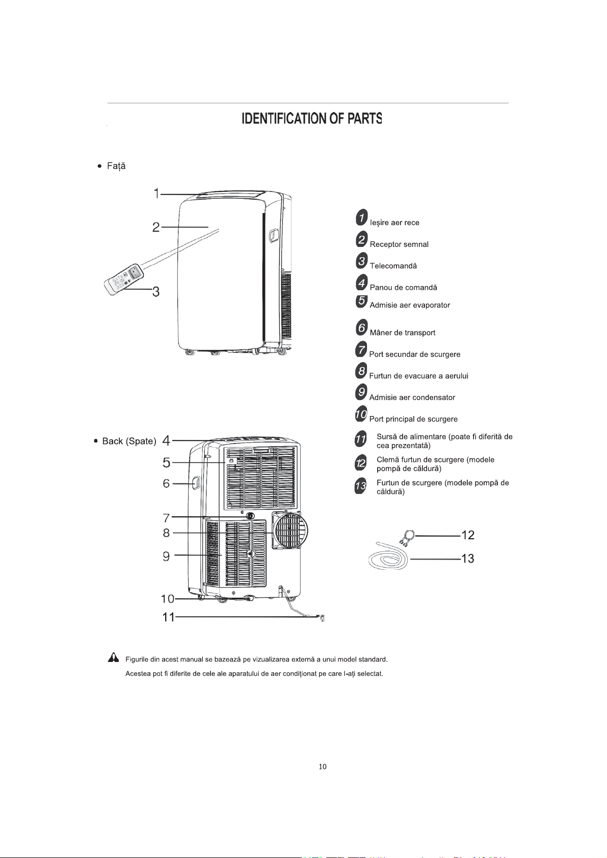
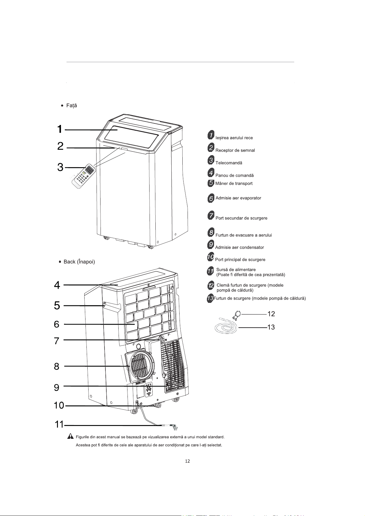
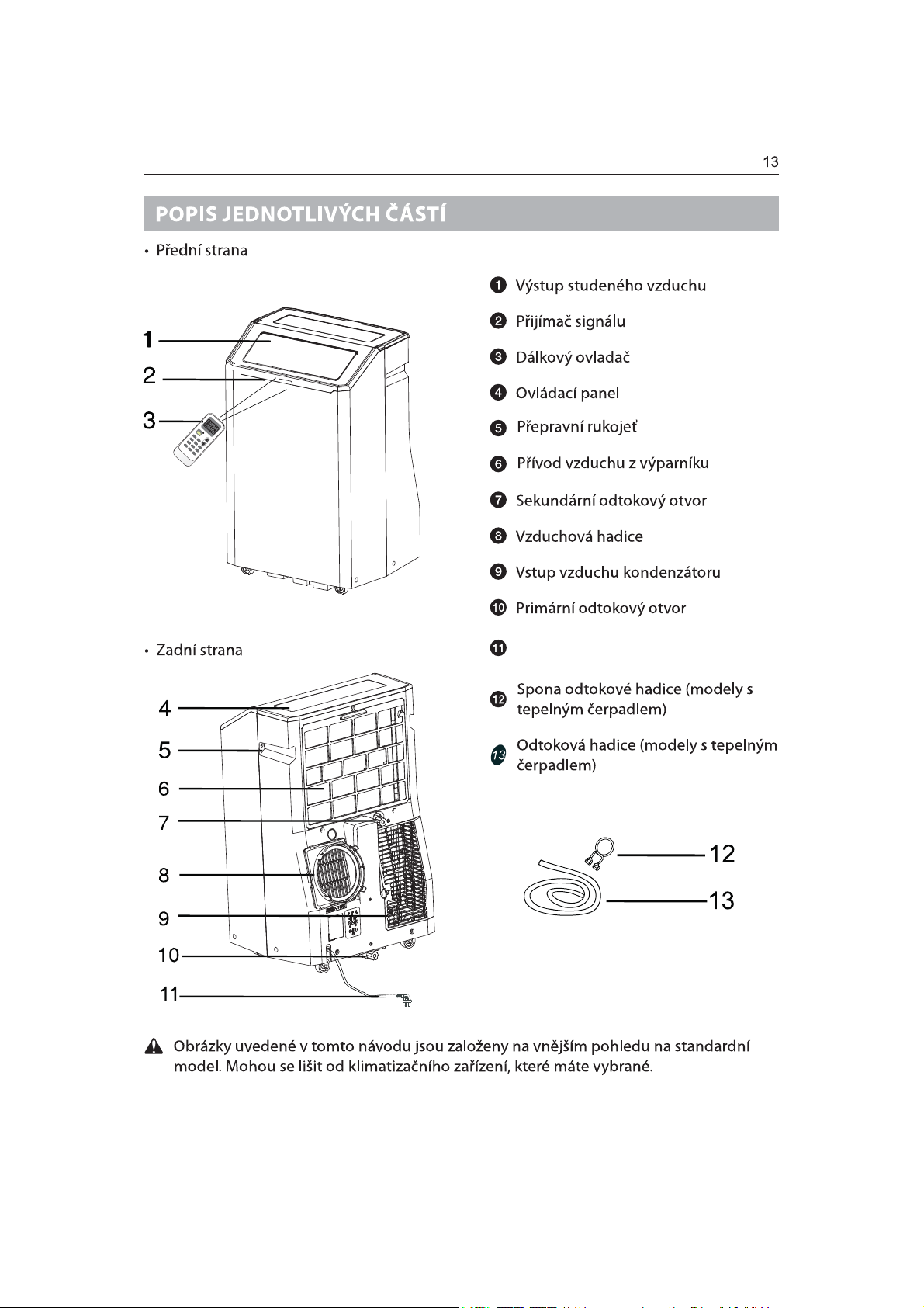
Front
Cool air outlet
Signal receptor
SW
IN
G
SMART
TIMER ON
I
F
EE
TIMER
L
O
FF CLOCK
DIMMER
Back
ONO
ON/OFF
N
OO
FF
FF
MODE FAN
SLEEP
SUPER
Control panel
Evaporator air intake
Transport handle
Secondary drain port
Air outlet ho se
Condenser air intake
Primary drain port
Power supply
(May differ from the one shown)
Remote control
13
11
The figures in this manual are based on the external view of a standard model.
They may differ from that of the air conditioner you have selected.
10
12
13
Page 13
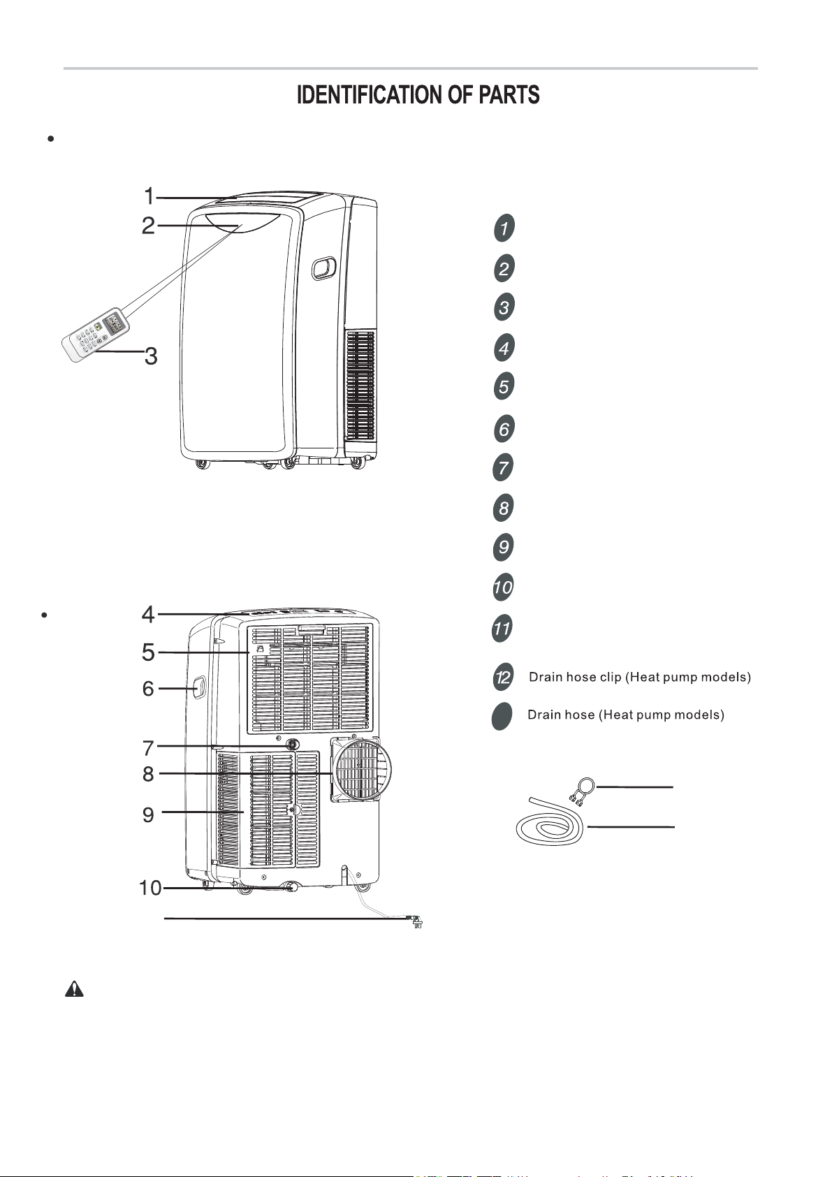
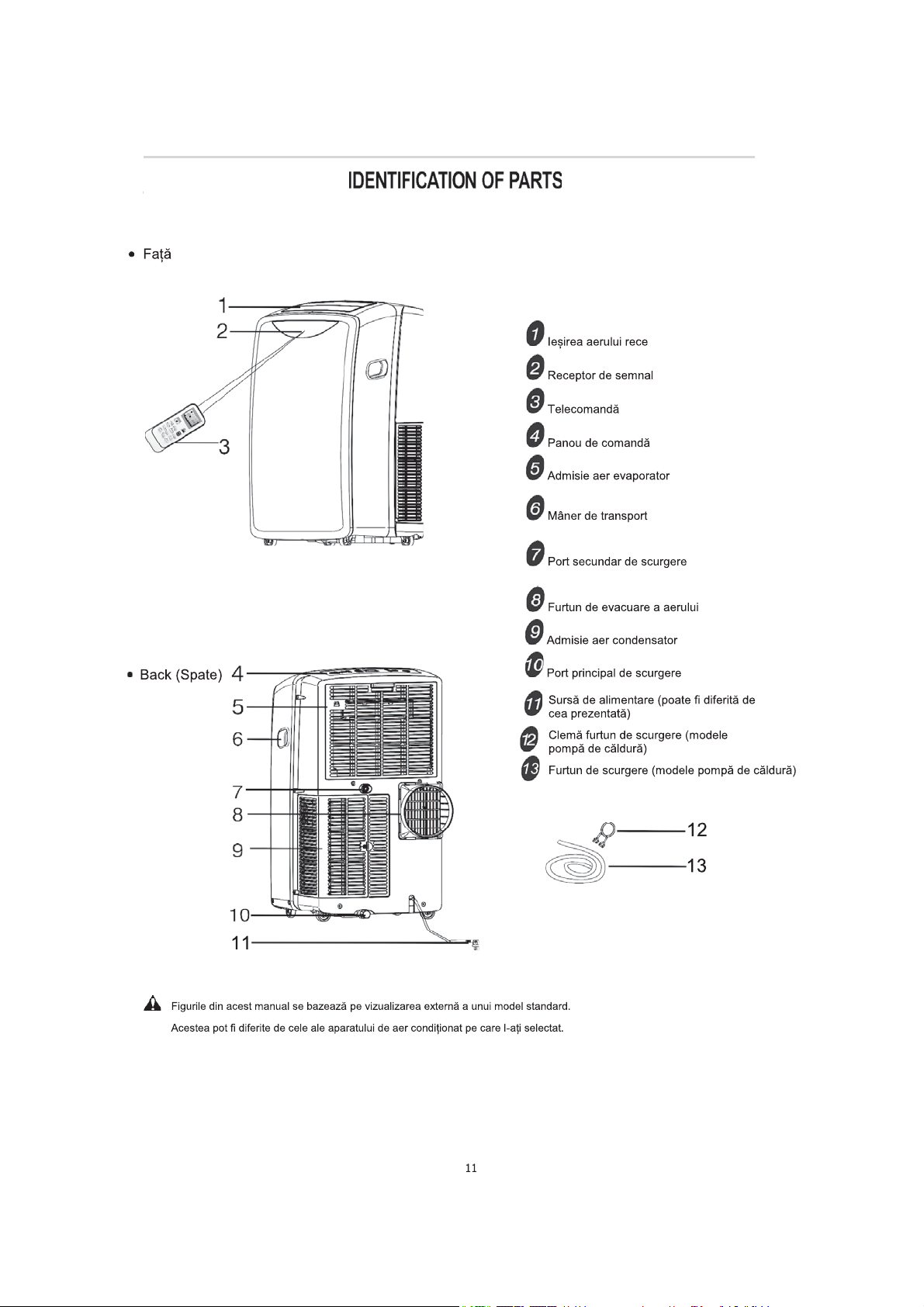
Front
Cool air outlet
Signal receptor
SW
SMART
TIMER ON
I
F
EE
TIMER
L
O
FF CLOCK
Back
ONO
ON/OFF
N
OO
FF
FF
MODE FAN
IN
G
SLEEP
SUPER
DIMMER
Control panel
Evaporator air intake
Transport handle
Secondary drain port
Air outlet ho se
Condenser air intake
Primary drain port
Power supply
(May differ from the one shown)
Remote control
13
11
The figures in this manual are based on the external view of a standard model.
They may differ from that of the air conditioner you have selected.
11
12
13
Page 14
O
O
N
N
O
O
F
F
F
F
ON/OFF
MODE FAN
SWING SLEEP
SMART
TIMER ON
IFEEL DIMMER
SUPER
TIMER OFF CLOCK
1
Page 15
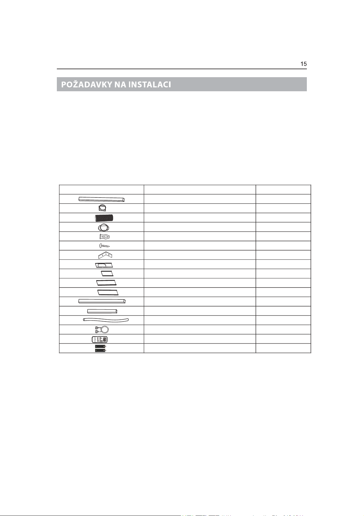
INSTALLATION REQUIREMENTS
Tools a nd Pa r ts
Gather the required tools and parts before starting installation. Read and follow the instructions provided with any tools listed here.
Tool s ne ed ed
Phillips screwdriver
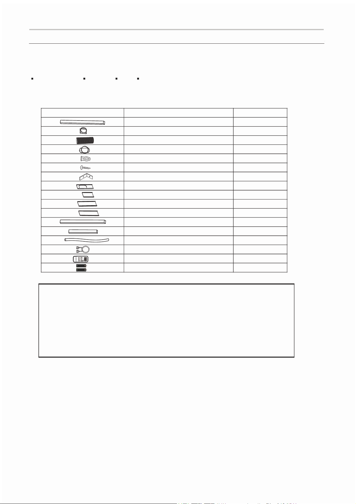
Parts supplied
The following parts are supplied with the portable Air conditioner.
Scissors
Pencil
Cordless drill and ¹8” bit
Part
Description
A. Foam seal
B. Coupling
C. Flexible exhaust hose
D. Window exhaust adapter
E. Rivets
F. Sc rews
G. Window-lock bracket
H. Outer slider section with vent
I. Inner slider section-short
J. inner slider section
K. Outer slider section
L. Foam seal-long
M. Foam seal-short
N. Drain hose (Heat pump models)
O. Drain hose clip (Heat pump models)
P. Remote control
Q. Standard AAA (1.5 volts) batteries
Quantity
1 pc
1 pc
1 pc
1 pc
4 pc
4 pc
2 pc
1 pc
1 pc
1 pc
1 pc
2 pc
2 pc
1 pc
1 pc
1 pc
2 pc
MERCURY FREE SUPER HEAVY DUTY R03 UM-4 SIZE AAA 1.5V
BEST USED BEFORE DATE CODE (MONTH-YEAR)
ON THE BOTTOM
Do Not Mix Old And New Batteries. Do Not Mix Alkaline,
Standard (Carbon - Zinc), Or Rechargeable (Nickel
- Cadmium) Batteries
DO NOT DISPOSE OF BATTERIES IN FIRE. BATTERIES MAY EXPLODE OR LEAK.
Note
Caution for ingestion
The battery may cause suffocation if swallowed by children
Non-rechargeable batt eries are not to be recharged
Exhausted batteries are to be removed from the product
1
Page 16
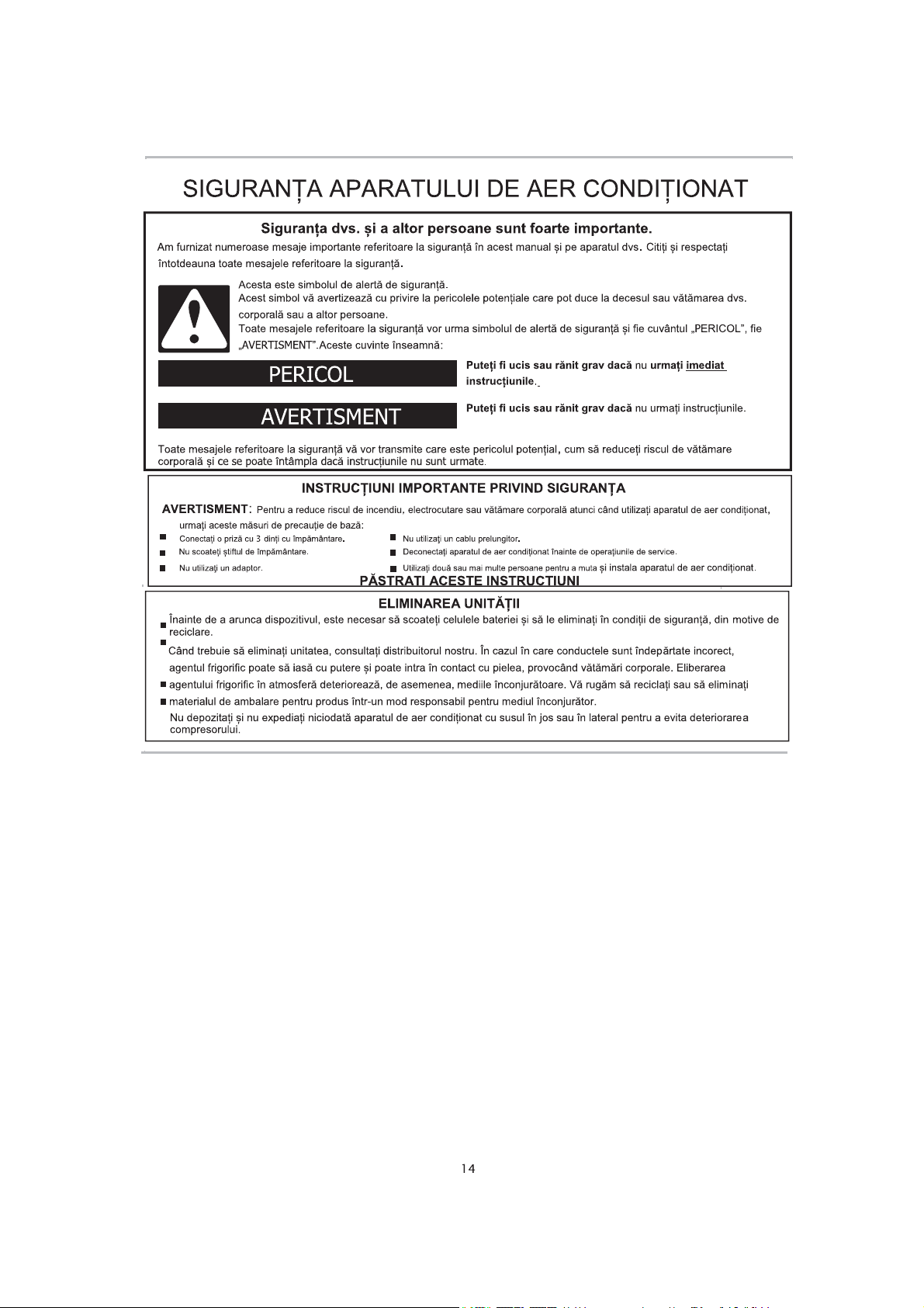
AIR CONDITIONER SAFETY
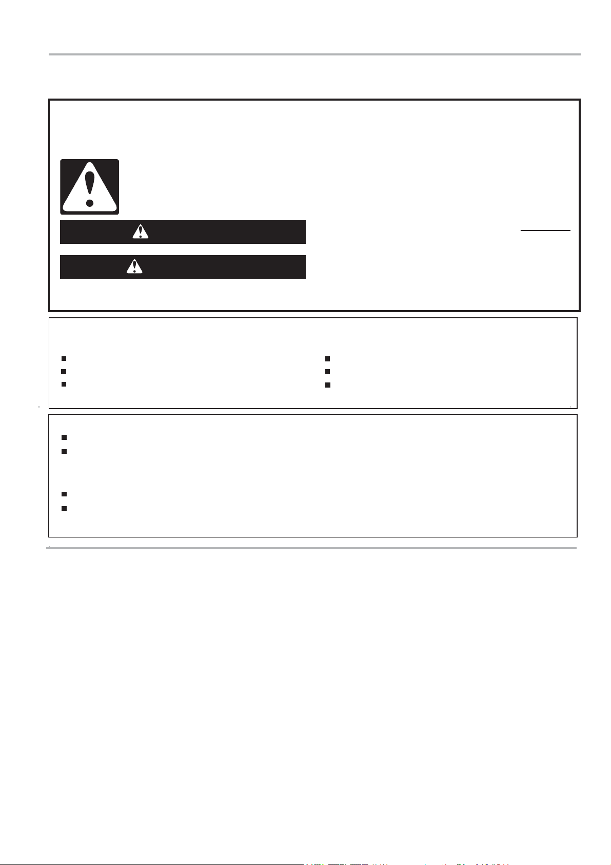
You safety and the safety of others are very important.
:H KDYH SURYLGHG PDQ\ LPSRUWDQW VDIHW\ PHVVDJHV LQ WKLV PDQXDO
PHVVDJHV.
7KLV LV WKH VDIHW\ DOHUW V\PERO.
7KLV V\PERO DOHUWV \RX WR SRWHQWLDO KD]DUGV WKDW FDQ NLOO RU KXUW \RX DQG RWKHUV.
$OO VDIHW\ PHVVDJHV ZLOO IROORZ WKH VDIHW\ DOHUW V\PERO DQG HLWKHU WKH ZRUG "D$1*(5" RU "WARNING ."
7KHVH ZRUGV PHDQ:
DANGER
WARNING
$OO VDIHW\ PHVVDJHV ZLOO WHOO \RX ZKDW WKH SRWHQWLDO KD]DUG LV, WHOO \RX KRZ WR UHGXFH WKH FKDQFH RI LQMXU\andtellyouwhatcan
happeniftheinstructionsarenotfollowed
DQG RQ \RXU DSSOLDQFH. $OZD\V UHDG DQG REH\ DOO VDIHW\
You can be killed or seriously injured if you don't immediately
follow instructions.
can be killed or seriously injured if you don't follow
You
instructions.
IMPORTANT SAFETY INSTRUCTIONS
WARNING:
3OXJ LQWR D JURXQGHG 3 SURQJ RXWOHW.
'R QRW UHPRYH JURXQG SURQJ.
'R QRW XVH DQ DGDSWHU.
7R UHGXFH WKH ULVN RI ILUH, HOHFWULFDO VKRFN RU LQMXU\ ZKHQ XVLQJ \RXU DLU FRQGLWLRQHU, IROORZ WKHVH EDVLF SUHFDXWLRQV:
'R QRW XVH DQ H[WHQVLRQ FRUG.
8QSOXJ DLU FRQGLWLRQHU EHIRUH VHUYLFLQJ.
8VH WZR RU PRUH SHRSOH WR PRYH DQG LQVWDOO DLU FRQGLWLRQHU.
SAVE THESE INSTRUCTIONS
DISPOSING OF THE UNIT
%HIRUHWKURZLQJWKHGHYLFHLWLVQHFHVVDU\WRSXOOEDFNWKHEDWWHU\FHOOVDQGJHWULGRIWKHPVDIHW\IRUUHF\FOLQJUHDVRQV
:KHQ\RXQHHGWRGLVSRVDORIWKHXQLWFRQVXOWRXUGHDOHU,ISLSHVDUHUHPRYHGLQFRUUHFWO\UHIULJHUDQWPD\EORZRXWDQG
FRPHLQWRFRQWDFWZLWK\RXUVNLQFDXVLQJLQMXU\5HOHDVLQJUHIULJHUDQWLQWRWKHDWPRVSKHUHDOVRGDPDJHVWKHHQYLURQPHQWV
SOHDVHUHF\FOHRUGLVSRVHRIWKHSDFNDJLQJPDWHULDOIRUSURGXFWLQDQHQYLURQPHQWDOO\UHVSRQVLEOHPDQQHU
1HYHUVWRUHRUVKLSWKHDLUFRQGLWLRQHUXSVLGHGRZQRUVLGHZD\VWRDYRLGGDPDJHWRWKHFRPSUHVVRU
7KHDSSOLDQFHLVQRWLQWHQGHGIRUXVHE\\RXQJFKLOGUHQRULQILUPSHUVRQVZLWKRXWVXSHUYLVLRQ<RXQJFKLOGUHQVKRXOGEH
VXSHUYLVHGWRHQVXUHWKDWWKH\GRQRWSOD\ZLWKWKHDSSOLDQFH
14
Page 17
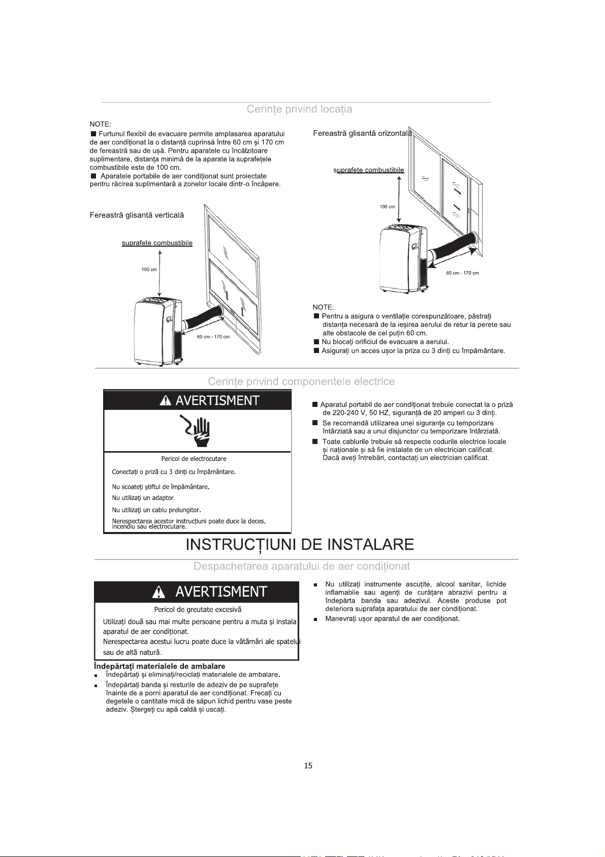
Location Requirements
NOTES:
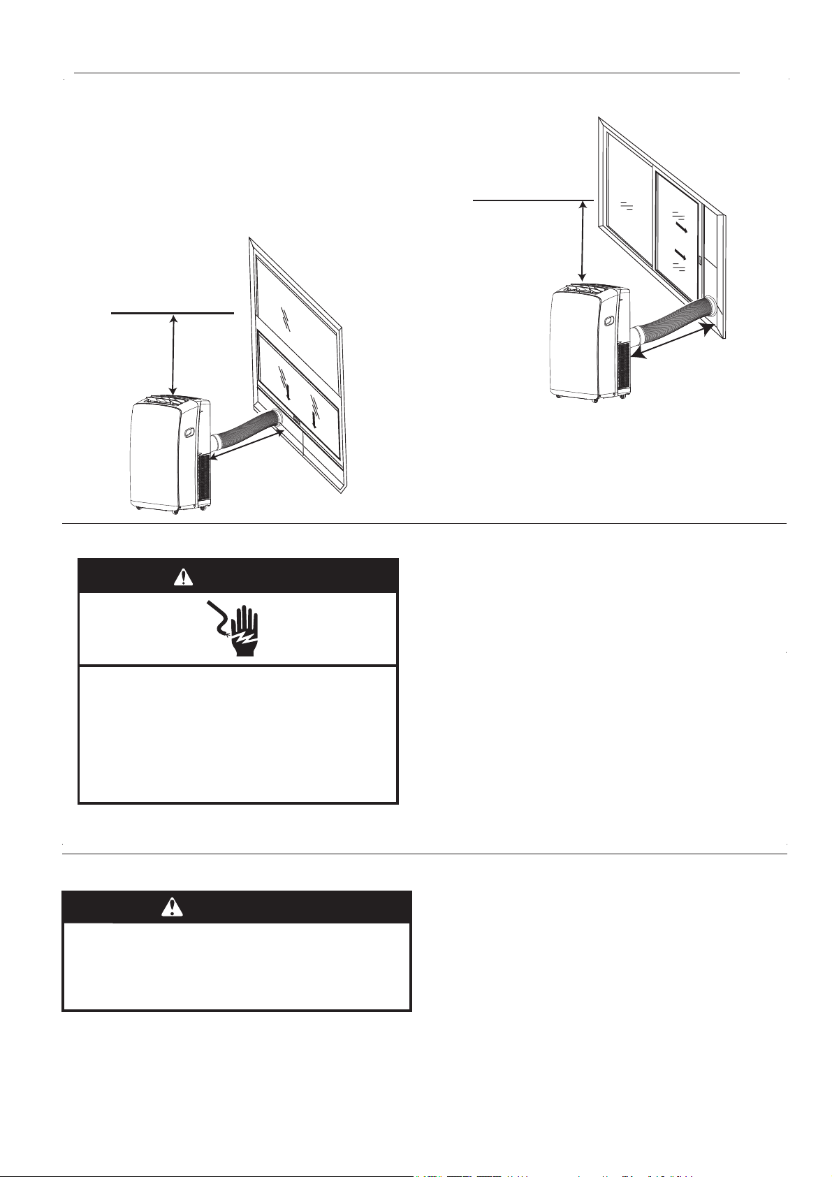
■ The flexible exhaust hose allows placement of the air
conditioner between 60 cm and 170 cm from window or door
For appliances with supplementary heaters, the minimum
clearance from the appliances to combustible surfaces is 100cm.
■ Portable air conditioners are designed as supplemental
cooling to local areas within a room.
Vertical Slide Widow
combustible surfaces
Horizontal Slide Window
.
combustible surfaces
100 cm
100 cm
60 cm - 170 cm
Electrical Requirements
WARNING
Electrical Shock Hazard
Plug into a grounded 3 prong outlet.
Do not remove ground prong.
Do not use an adapter.
Do not use an extension cord.
Failure to follow these instructions can result in death,
fire, or electrical shock.
60 cm - 170 cm
NOTES:
■ To ensure proper ventilation, keep the required distance from
the return air outlet to the wall or other obstacles at least 60
cm.
■ Do not block the air outlet.
■ Provide easy access to the grounded 3 prong outlet.
portable
■ The air conditioner should be connected to a 220-
240V, 50 HZ, 20-amp fuse grounded 3 prong outlet.
■ The use of a time-delay fuse or time-delay circuit breaker is
recommended.
■ All wiring must comply with local and the national electrical
codes and be installed by a qualified electrician. If you have
any questions, contact a qualified electrician.
INSTALLATION INSTRUCTIONS
Unpack the Air Conditioner
WARNING
Excessive Weight Hazard
Use two or more people to move and install
air conditioner.
Failure to do so can result in back or other injury.
Remove packaging materials
■ Remove and dispose of/recycle packaging materials.
■
Remove tape and glue residue from surfaces before turning
on the air conditioner. Rub a small amount of liquid dish soap
over the adhesive with your fingers. Wipe with warm water
and dry.
■ Do not use sharp instruments, rubbing alcohol, flammable
fluids, or abrasive cleaners to remove tape or glue. These
products can damage the surface of your air conditioner.
■ Handle the air conditioner gently.
15
Page 18
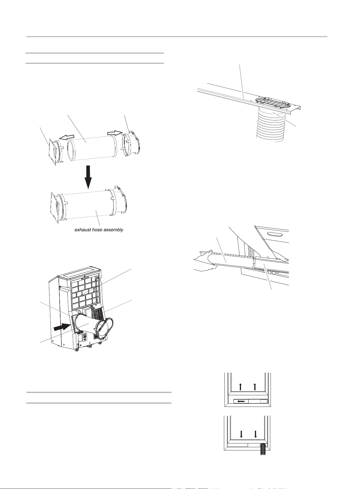
Install Portable Air Conditioner(on the window)
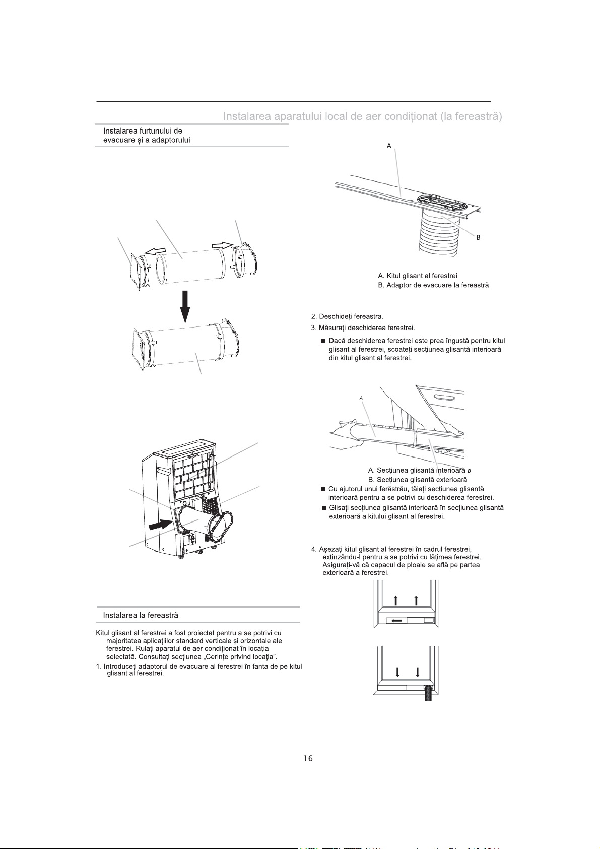
Install Exhaust Hose and Adapter
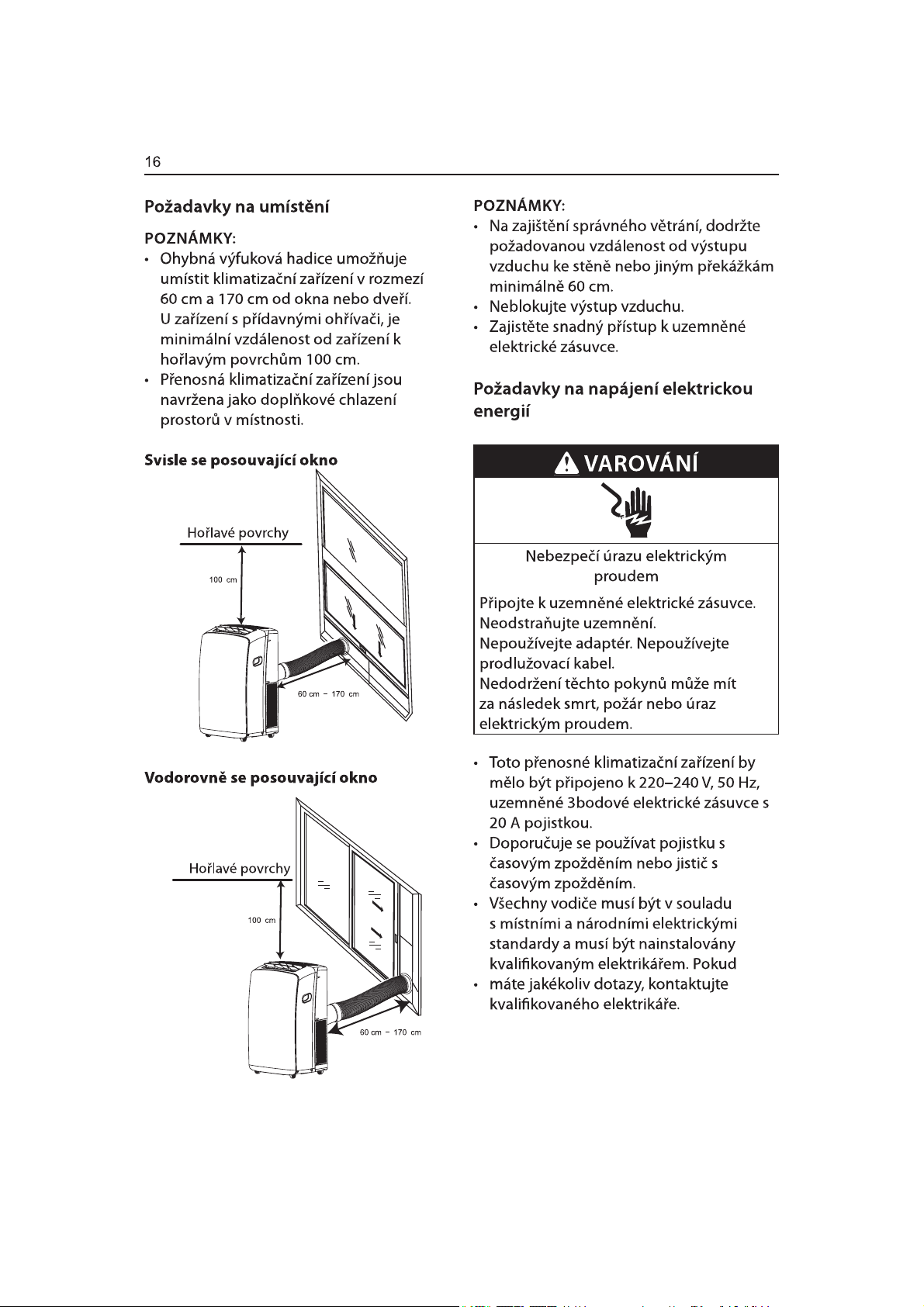
1. Roll the air conditioner to selected location. see “Location
Requirements.”
2. 3UHSDULQJWKHH[KDXVWKRVHDVVHPEO\
3UHVVWKHFRXSOLQJDQGWKHZLQGRZH[KDXVWDGDSWHULQWR
WKHIOH[LEOHH[KDXVWKRVH%RWKWKHFRXSOLQJDQGZLQGRZ
H[KDXVWDGDSWHUKDYHLQWHJUDOFOLSVWKDWVQDSRQWRWKHKRVH
IOH[LEOHH[KDXVWKRVH
FRXSOLQJ
ZLQGRZH[KDXVWDGDSWHU
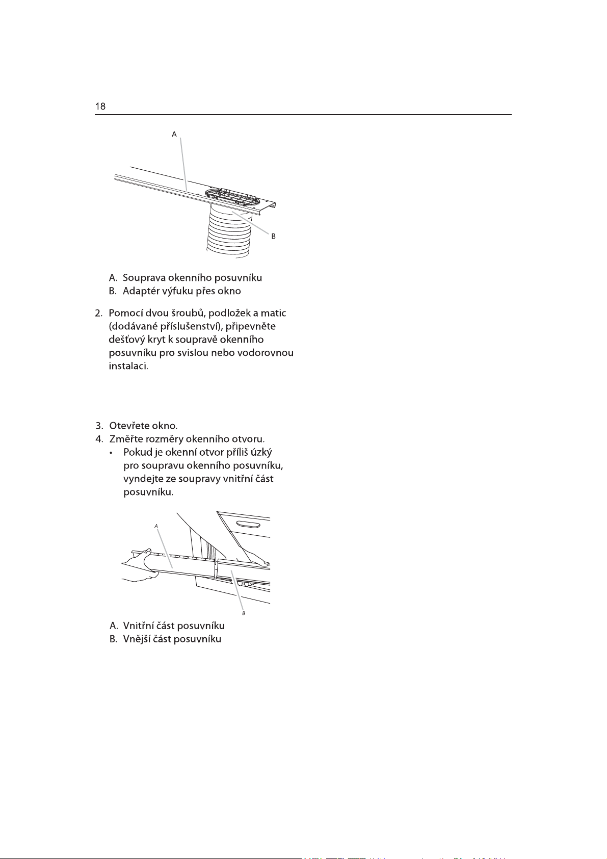
A
B
A. Window slider kit
B. Window exhaust adapter
2. Open the window.
3. Measure the window opening.
If the window opening is too narrow for the window slider kit,
■
remove the inner slider section from the window slider kit.
. Insert the d
ummy coupling into the slot on the back of the air
conditioner.
. Slide down to lock the hose into place.
B
C
A. Evaporator air intake
B. D
ummy coupling
C. Flexible exhaust hose
D. Condenser air intake
Window Installation
A
A
A. Inner slider section
D
Using a saw, cut the inner slider section to fit the window
■
B. Outer slider section
B
opening.
Slide the inner slider section into the outer slider section of
■
the window slider kit.
4. Place the window slider kit into the window, extending it to fit
the width of the window. Be sure the rain cover is on the
outside of the window.
Your window slider kit has been designed to fit most standard
vertical and horizontal window applications. Roll the air
conditioner to selected location. see “Location Requirements.”
1. Insert the windows exhaust adapter into the slot on the window
slider kit.
Page 19
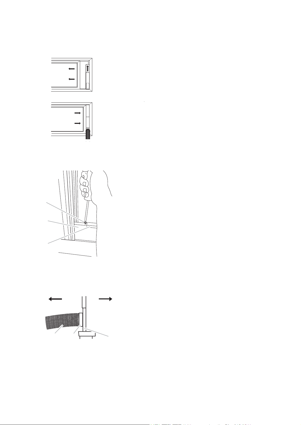
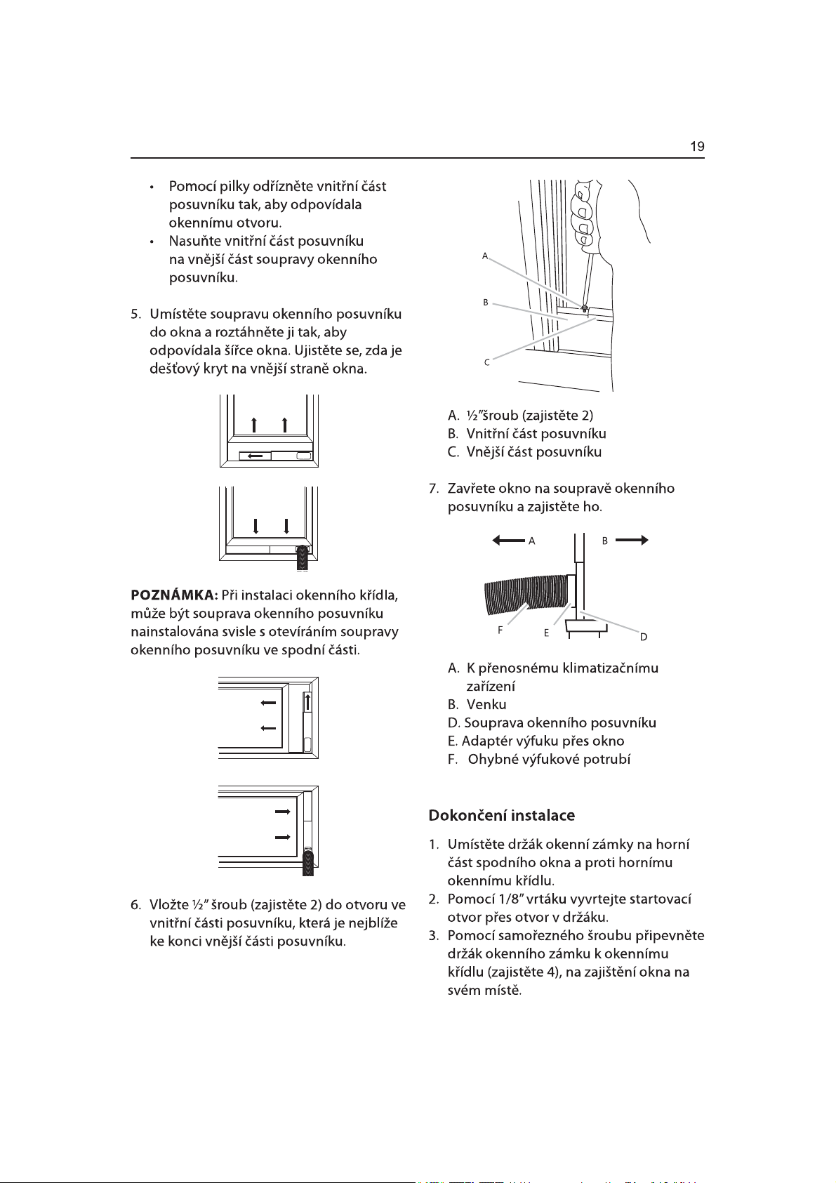
NOTE: For casement window installation, the window slider kit
may be installed vertically with the window slider kit opening
at the bottom.
5. Inset ½” screw (provide 2) into the hole in the inner slider
section that is closest to the end of the outer slider section of
A
B
C
A. ½”screw (provide 2)
B. Inner slider section
C. Outer slider section
6. Close the window onto the window slider kit to secure.
AB
E
A. To air conditioner
portable
B. Outdoors
D
C
C. Window slider kit
D. Window exhaust adapter
E. Flexible exhaust hose
Page 20
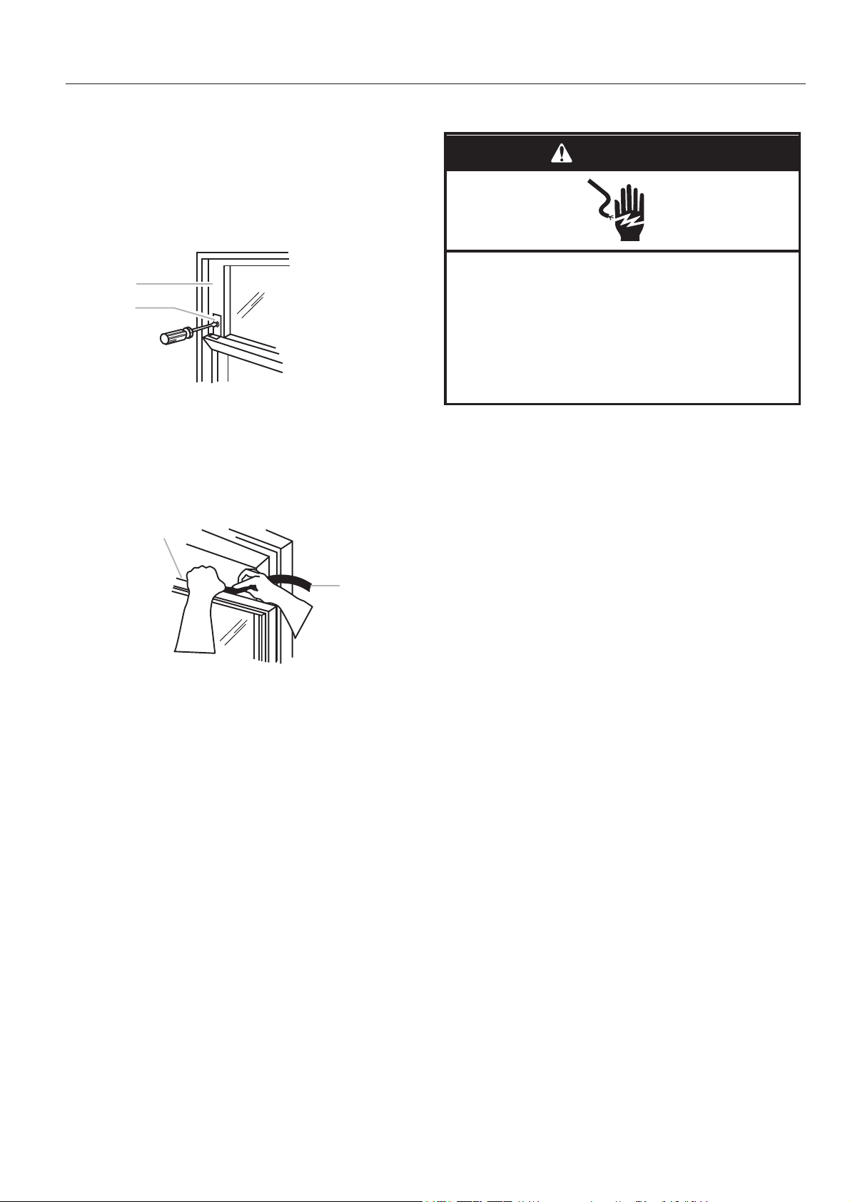
Complete Installation
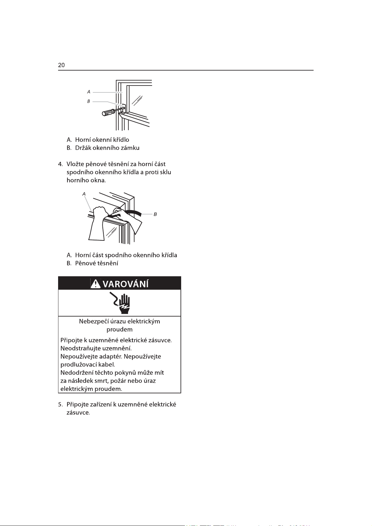
1. Place the window-lock bracket on top of the lower window and
against the upper window sash.
2. Use 1/8” drill bit to drill a starter hole through the hole in the
bracket.
3. Attach the window-lock bracket to the window sash with wood
screw(provide 4) to secure the window in place.
A
B
A. Upper window sash
B. Window-lock bracket
4. Insert the foam seal behind the top of the lower window sash
and against the glass of the upper window.
WARNING
Electrical Shock Hazard
Plug into a grounded 3 prong outlet.
Do not remove ground prong.
Do not use an adapter.
Do not use an extension cord.
Failure to follow these instructions can result in death,
fire, or electrical shock.
5. Plug into a grounded 3 prong outlet.
A
A. Top of lower window sash
B. Foam seal
B
18
Page 21
LOCAL AIR CONDITIONER USE
Operating your air conditioner properly helps you to local
obtain the best possible results.
This section explains proper air conditioner operation.
IMPORTANT:
The air conditioner display shows the setting temperature.
■
■ Only in standby mode the display shows ambient ■ temperature
When changing modes while the air conditioner is
operation, the compressor will stop for 3 to 5 minutes before
■
If a button is pressed during this time, the compressor will
not restart fo another 3 to 5 minutes.
■
In Cooling or Dry mode, the compressor and condenser fan
will stop when the room temperature reaches the set
temperature.
NOTE: In the event of a power failure, your air conditioner will
operate at the previous settings when the power is restored.
Operating condition
COOLING
HEATING
DRY
The temperature of some products is allowed beyond the range. In specific situation, please consult the merchant.
If the air conditioner runs in COOLING or DRY mode withdoor or window opened for a long time when relative
humidity is above 80%,dew may drip down from the outlet.
The best room temperature for the appliance work is 21oC~35 C
The best room temperature for the appliance work is 7 C~20 C
The best room temperature for the appliance work is 19 C~35 C
o
oo
oo
Page 22
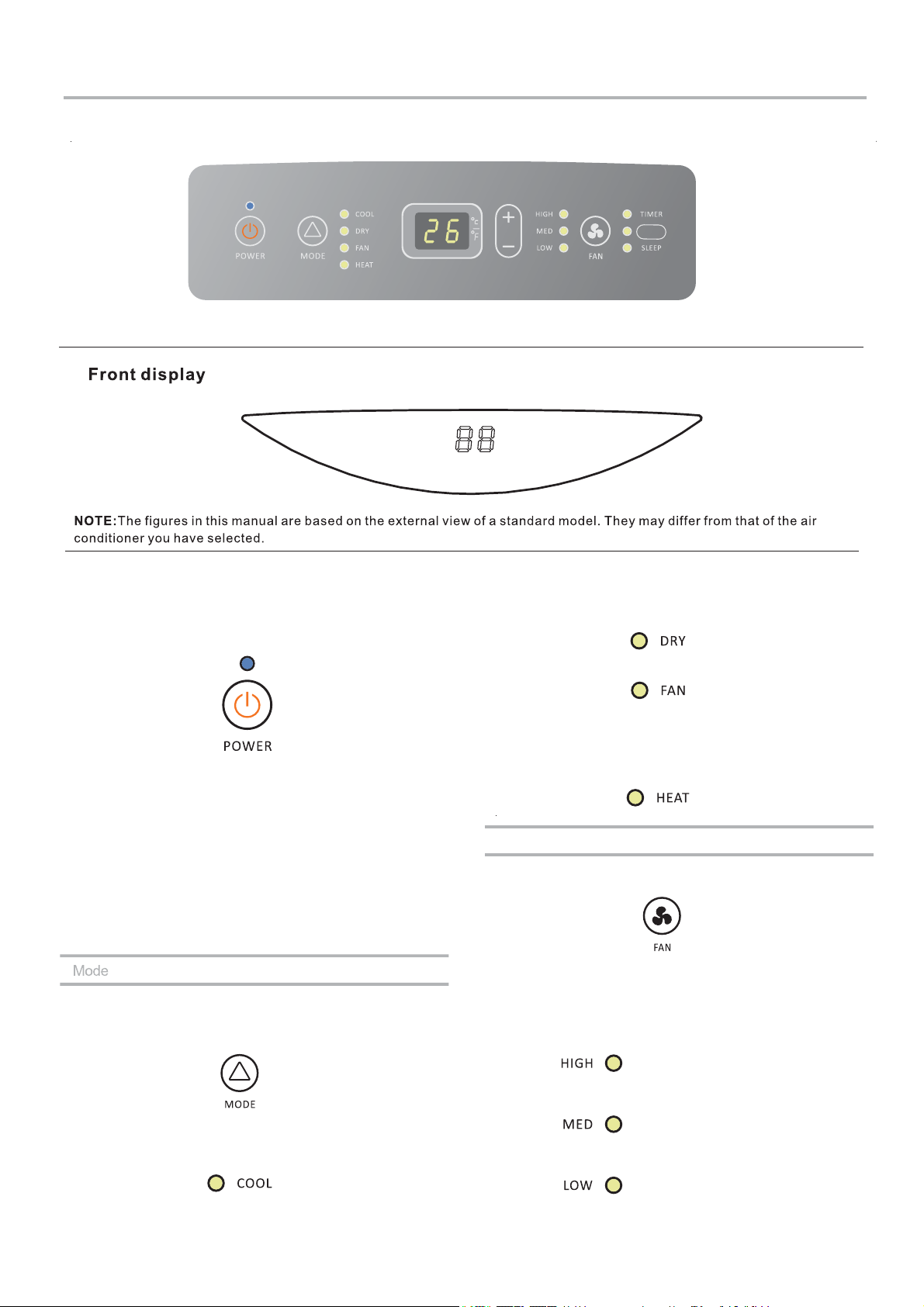
Starting Your Local Air Conditioner
SILENT
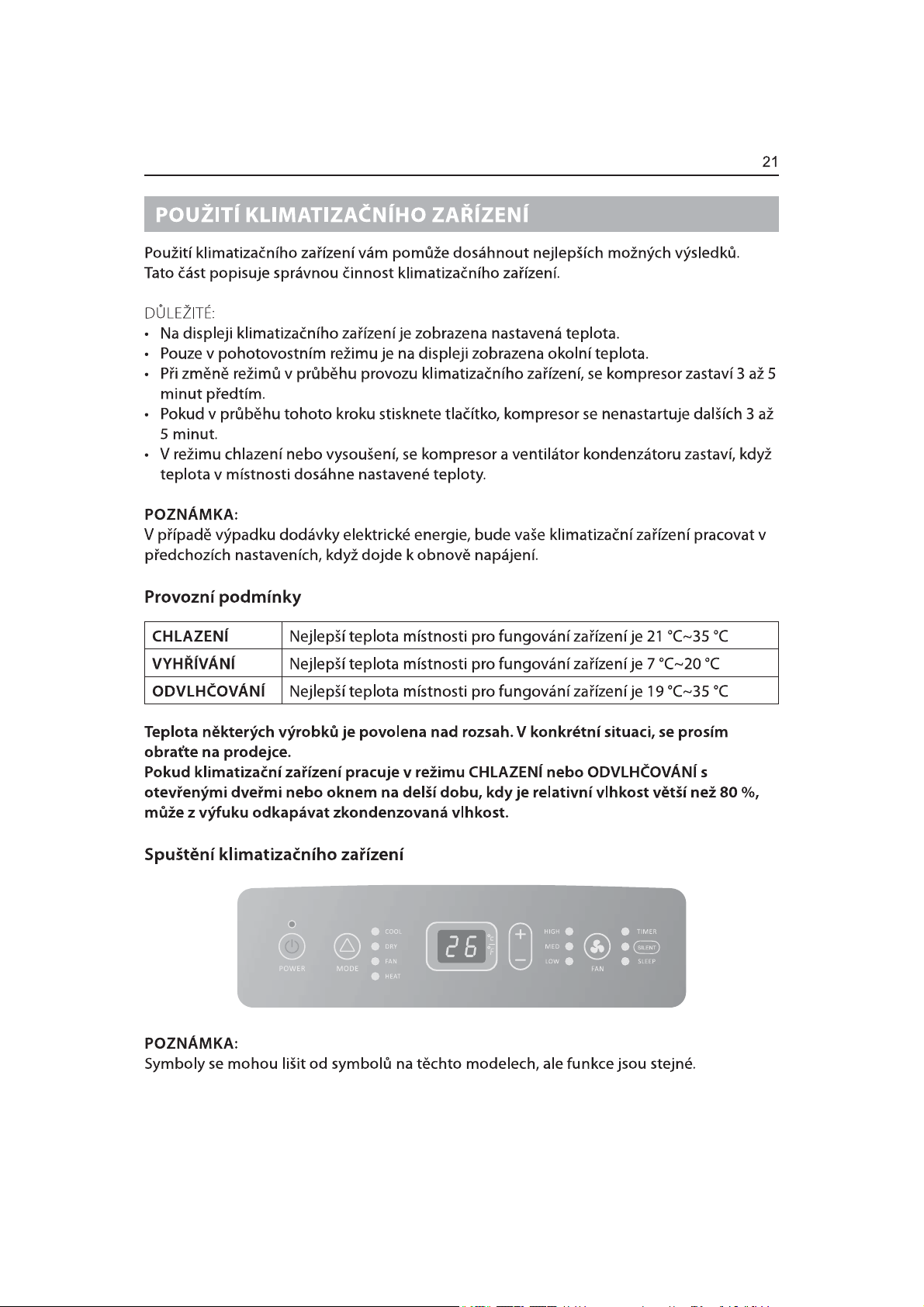
NOTE:The symbols may be different from these models, but the functions are similar.
1. Select the mode. See " MODE ".
2. Select the fan speed. See " FAN ".
3. Set the temperature. See "TEMPERATURE".
4. Press POWER button to start the air conditioner.
NOTE:
When the air conditioner is turned on, it will run according to
the previous setting.
Only if the unit is operated in UNLIKELY VERY HUMID air,
water will be collected in the container inside the unit. If the
water container is full, the air conditioner will stop. The
screen will displays “E5” to inform you to empty the internal
container.
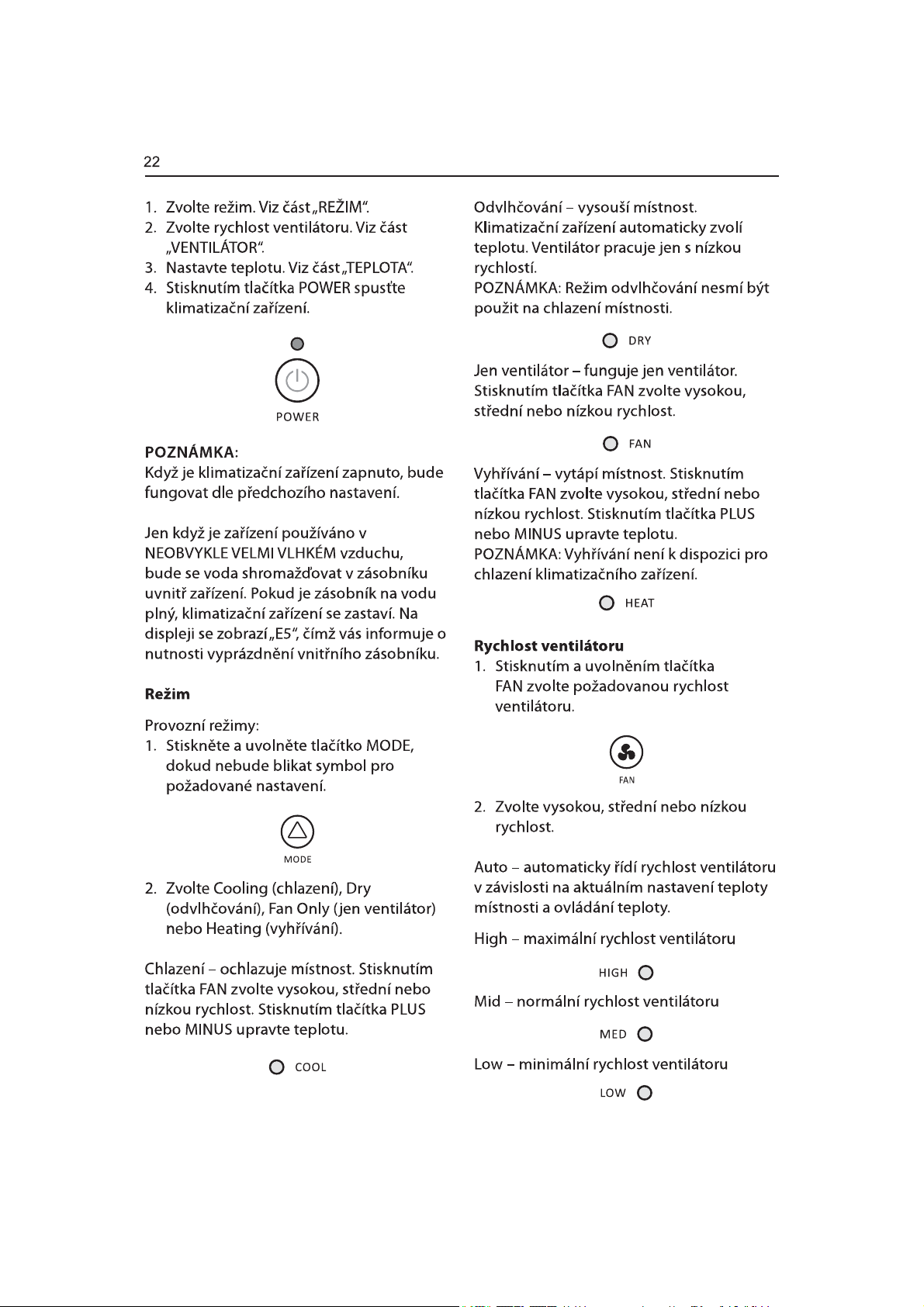
Operating modes:
1. Press and release MODE until you see the symbol flashes for the
desired setting.
Dry-Dries the room. The air conditioner automatically selects
the temperature. The fan
NOTE:Dry mode should not be used to cool the room.
Fan Only-Only the fan runs. Press FAN to select High,
Mid or Low.
Heating-heats the room. Press FAN to select high,
Mid or Low. Press the PLUS or MINUS button to adjust the
temperature.
runs on Low speed only.
NOTE: Heating is NOT available for cooling only air conditioner.
Fan Speed
1. Press and release FAN to choose the
2. Choose High, Mid or Low.
Auto-automatically controls the fan speed depending on the
current room temperature and temperature control setting.
High-for maximum fan speed
desired fan speed.
2. Choose Cooling, Dry, Fan Only or Heating.
Cooling-Cools the room. Press FAN to select High,
Mid or Low. Press the Plus or Minus button to adjust the
temperature.
Mid-for normal fan
Low-for minimum fan speed
2
speed
Page 23
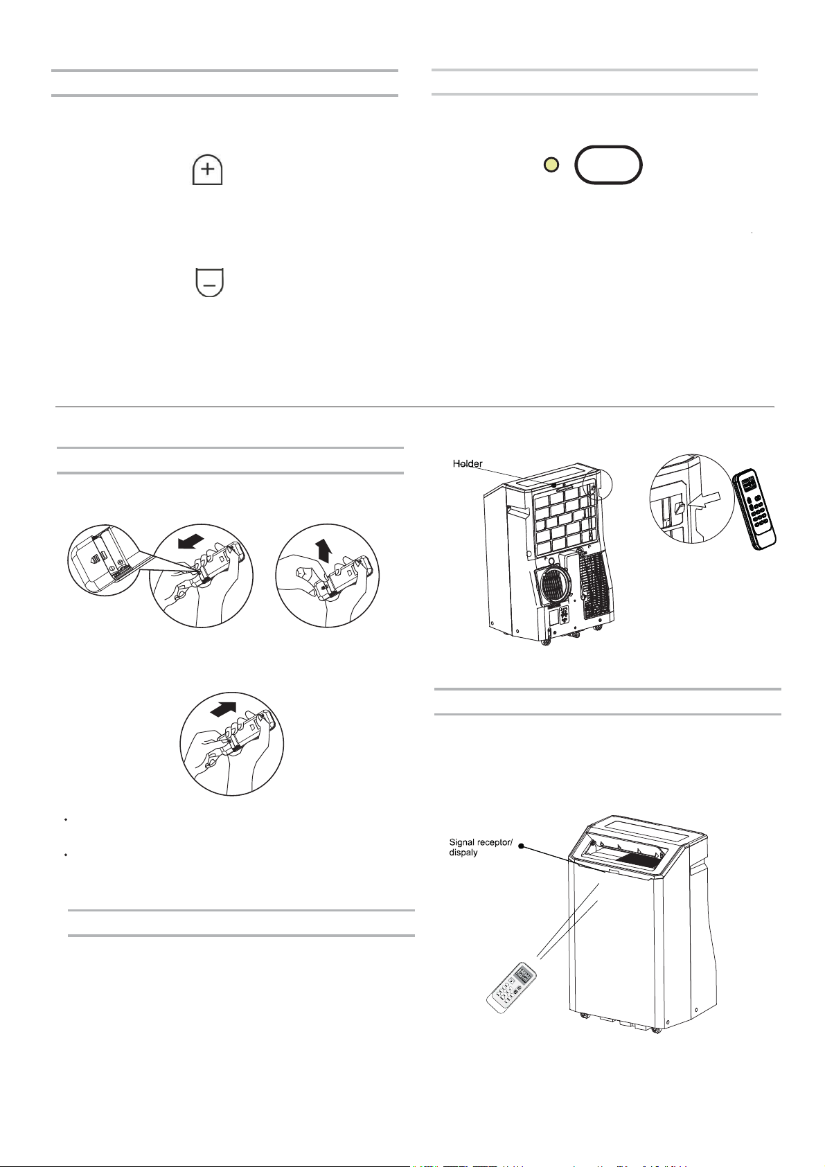
Temperature
SILENT
Press the PLUS button to raise the temperature. Press the PLUS
button once to increase the set temperature by
1°C.
PLUS
Press the MINUS button to lower the
button once to decrease the set temperature by 1°C.
temperature. Press the MINUS
MINUS
NOTE:
In the Cooling mode, the temperature can be set between
16°C and 30°C .
In Fan Only mode, the temperature cannot be set.
Using the Remote Control
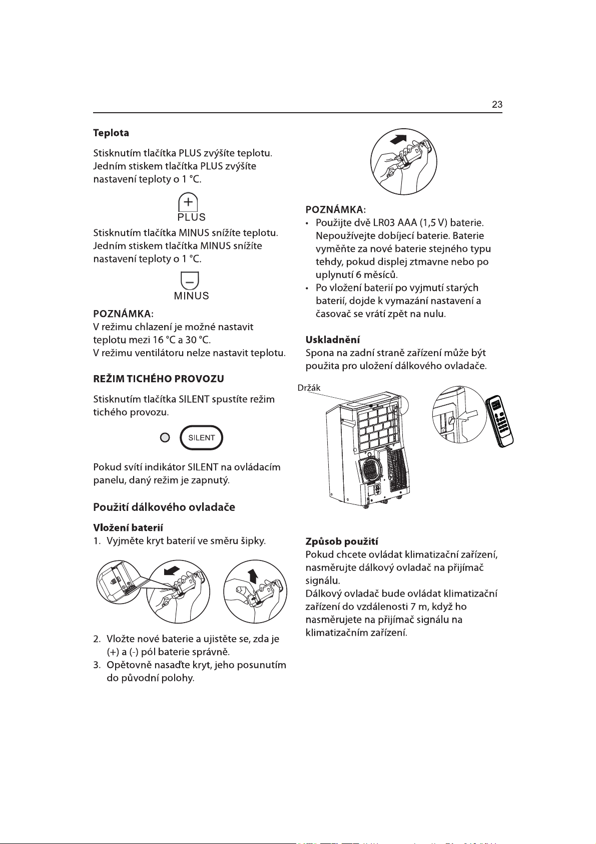
Insert the Batteries
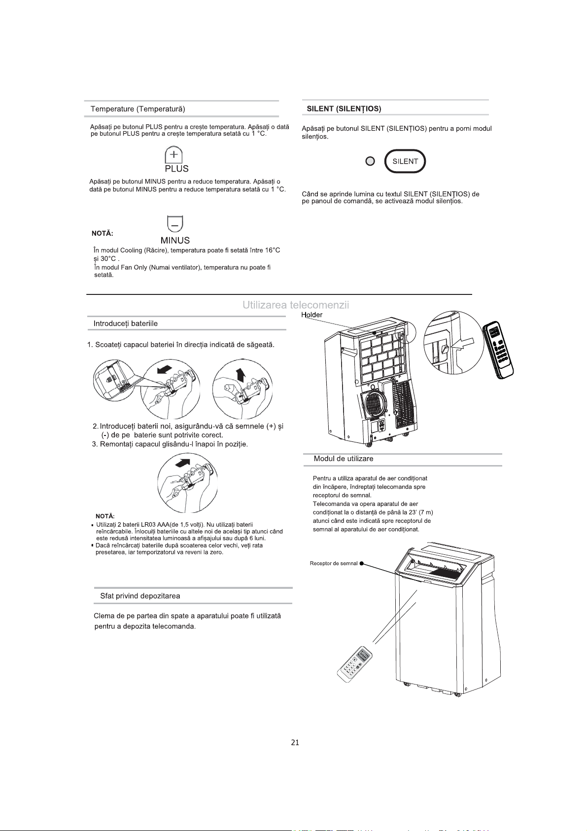
1. Remove the battery cover to the arrow direction.
Press SILENT button to start the silent mode.
SILENT
When the SILENT light on the control panel lights,
mode turn on.
the silent
2. Insert new batteries making sure that the (+) and (-) of
battery are matched correctly.
3. Reattach the cover by sliding it back into position.
NOTE:
Use 2 LR03 AAA(1.5volt) batteries. Do not use rechargeable batteries.
Replace batteries with new ones of the same type when the display
becomes dim, or after 6 months.
If you reload batteries over after removing the old ones, you will miss
the presetting and the timer will go back to Zero.
Storage trip
The clip on the back of the unit can be used to store the remote
control.
How to Use
To operate the room air conditioner, aim
the remote controller to the signal receptor.
The remote control will operate the air
conditioner at a distance of up to 23’ (7m) when
pointing at signal receptor of the air conditioner.
2
Page 24
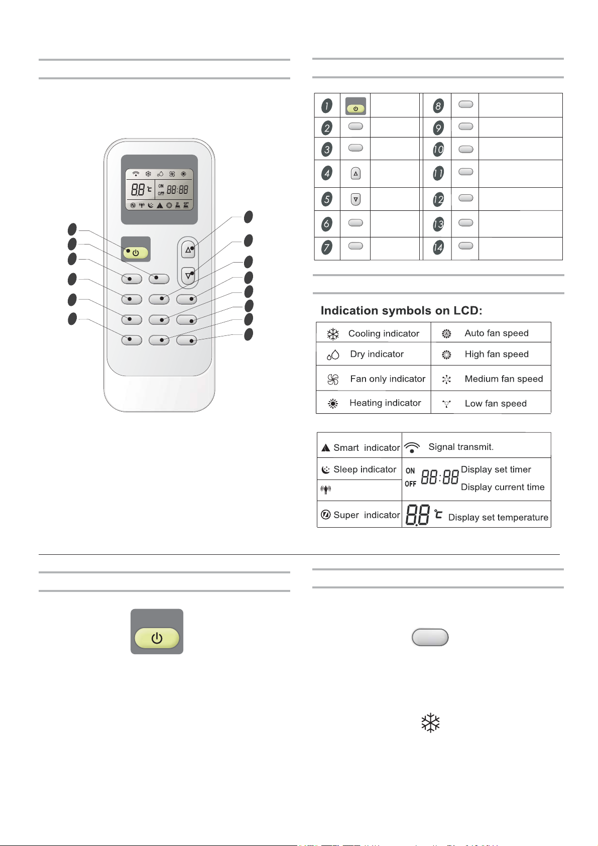
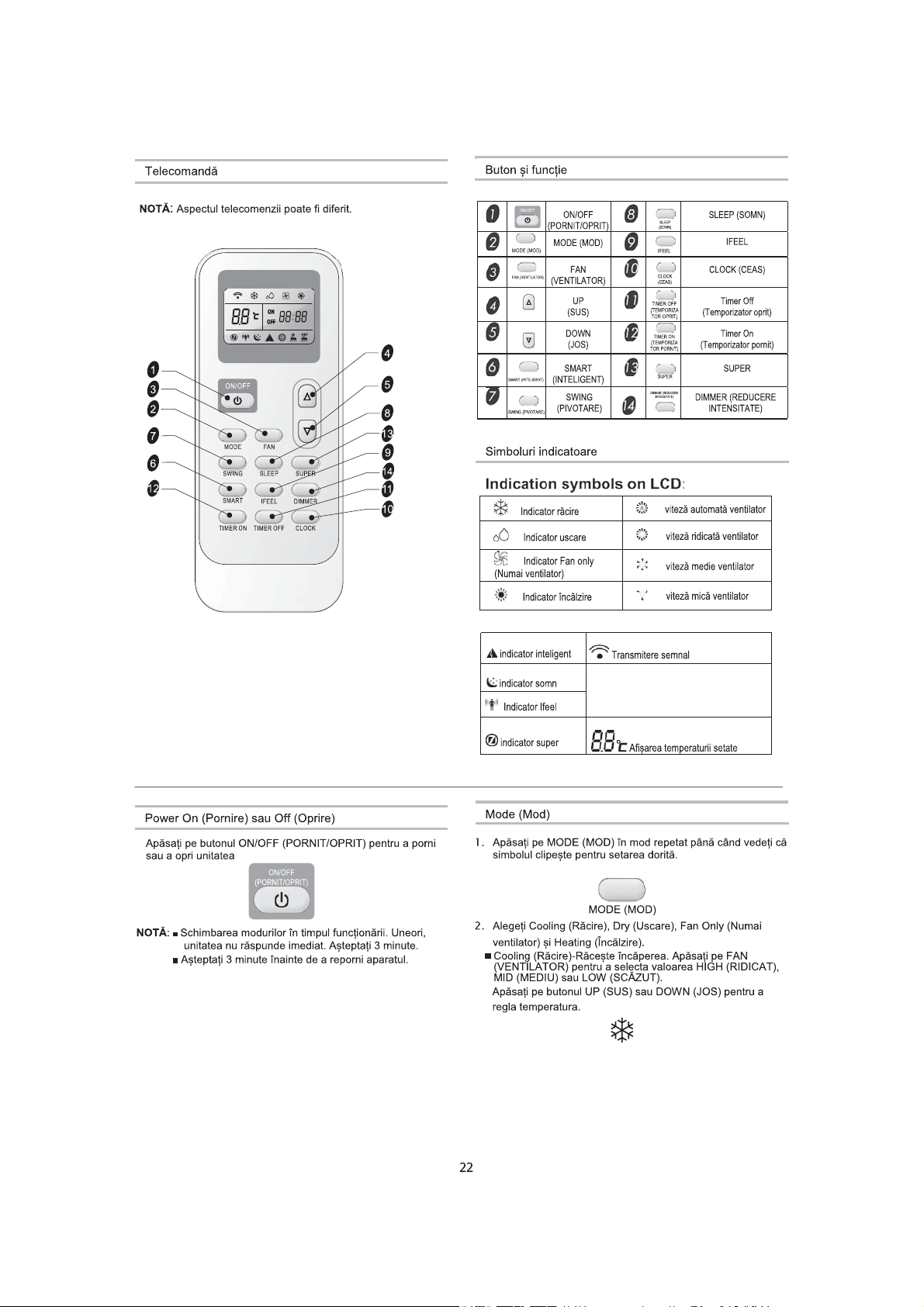
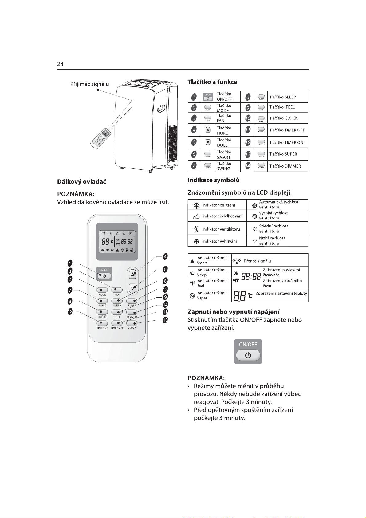
Remote control
Button and Function
NOTE:
Remote control may differ in appearance.
ON
OFFON OFF
1
3
ON/OFF
2
7
6
12
MODE FAN
SLEEP
SWING
SMART
TIMER ON TIMER OFF CLOCK
SUPER
IFEEL DIMMER
13
14
11
10
ON/OFF
ON/OFF
MODE
MODE
FAN
FAN
UP
DOWN
4
5
SMART
SWING
SMART
SWING
SLEEP
IFEEL
CLOCK
TIMER OFF
TIMER ON
SUPER
DIMMER
SLEEP
IFEEL
CLOCK
Timer Off
Timer On
SUPER
DIMMER
8
9
Indication symbols
Power On or Off
Press ON/OFF button to turn on or off the unit
ON/OFF
Changing modes during operating. Sometimes the unit
■
NOTE:
does not response at once. Wait 3 minutes.
Wait 3 minutes before restarting the appliance.
■
Ifeel indicator
Mode
1. Press MODE repeatedly until you see the symbol flashes for the
desired setting.
MODE
2. Choose Cooling, Dry, Fan Only and heating.
■
Cooling-Cools the room. Press FAN
MID or LOW.
Press the UP or DOWN button to adjust the temperature.
to select AUTO, HIGH,
2
Page 25
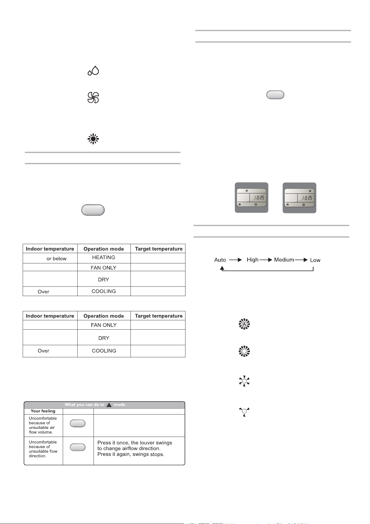
■
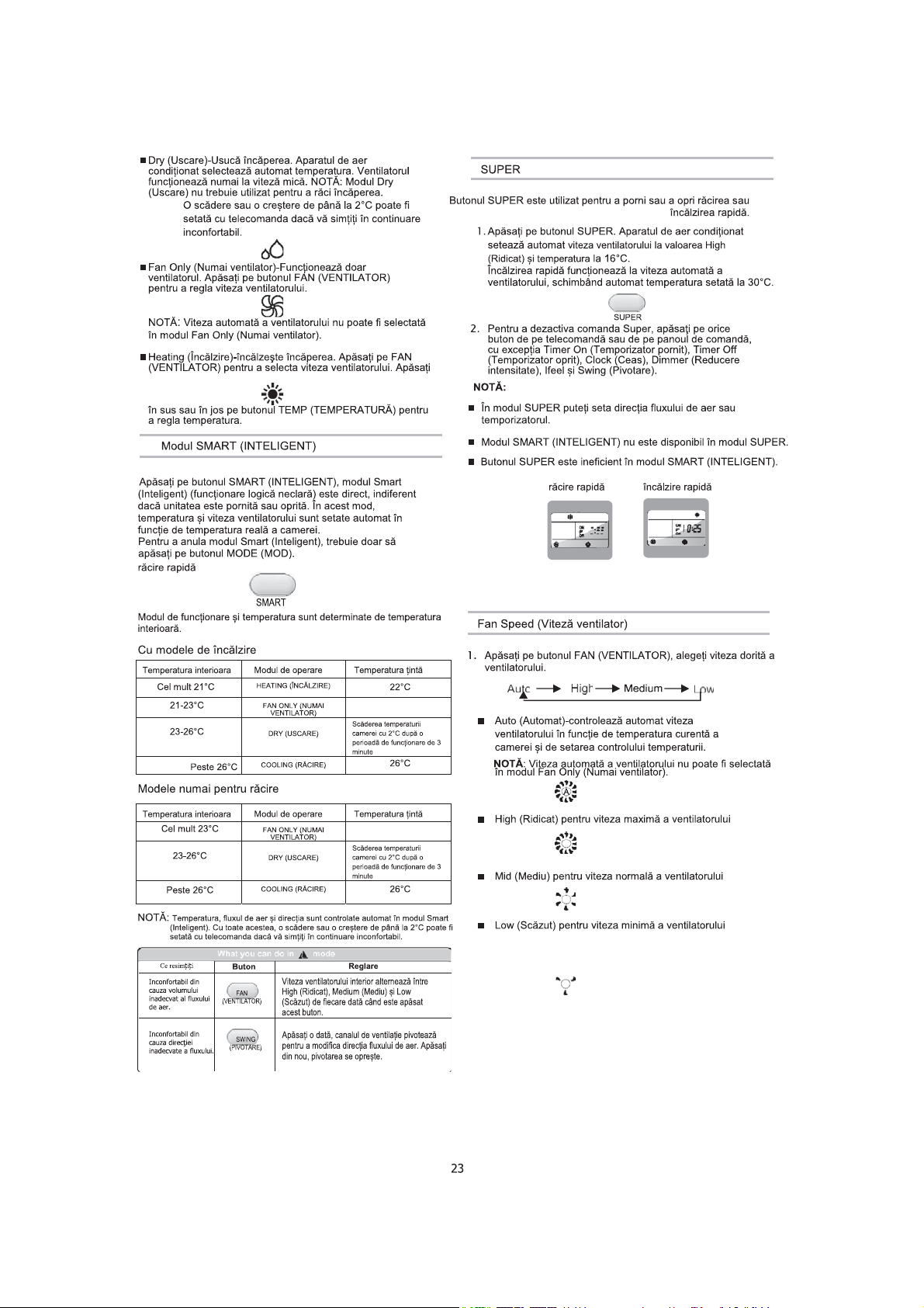
Dry-Dries the room. The air conditioner automatically
selects the temperature. The fan runs on Low speed only.
NOTE: Dry mode should not be used to cool the room.
A decrease or rise of up to can be set with the
2°C
remote controller if you still feel uncomfortable.
■
Fan Only-Only the fan runs. Press FAN button to adjust
fan speed.
SUPER
SUPER button is used to start or stop fast cooling or heating.
1. Press SUPER
sets the fan speed to High and the temperature
Fast heating operates at auto fan speed,changing the set
temperature automatically to
button. The air conditioner automatically
to 16°C.
30°C.
NOTE: Auto fan speed cannot be selected in Fan Only mode.
■
Heating-Heats the room. Press FAN to select the fan speed.
Press the up or down TEMP button to adjust the temperature.
SMART Mode
Press the SMART button, Smart mode (fuzzy logic operation) is
directly regardless of the unit is on or off. In this mode,
temperature and fan speed are automatically set based on the
actual room temperature.
To cancel Smart Mode, just press the MODE button.
SMART
Operation mode and temperature are determined by indoor temperature.
With Heater models
21°C
21-23°C
23-26°C
26°C
22°C
Room temperature
decrease 2 after
operate for 3 minutes
°C
26°C
Cooling only models
2. To turn off Super control, press any button on the remote
SUPER
control or control panel except Timer On, Timer Off, Clock,
Dimmer,Ifeel and Swing.
NOTE:
■
In the SUPER mode you can s et airf low dir ectio n or time r.
■
SMART mode are not available in SUPER mode.
■
SUPER button is ineffective in SMART mode.
fast cooling
fast heating
ON
OFF
ON
OFF
Fan Speed
1. Press FAN button, Choose desired fan speed.
■ Auto-Automatically controls fan speed depending on
current room temperature and temperature control
setting.
NOTE:
Auto fan speed cannot be selected in Fan Only
mode.
23°C or below
Room temperature
23-26°C
26°C
NOTE:
Temperature, airflow and direction are controlled
decrease 2 after
operate for 3 minutes
automatically in smart mode. However, a decrease or rise of
up to can be set with the remote controller if you still feel
2°C
uncomfortable.
Button
Adjustment
Indoor fan speed alternates among
FAN
SWING
High, Medium and Low each time
this button is pressed.
°C
26°C
■ High for maximum fan speed
■ Mid for normal fan speed
■ Low for minimum fan speed
2
Page 26
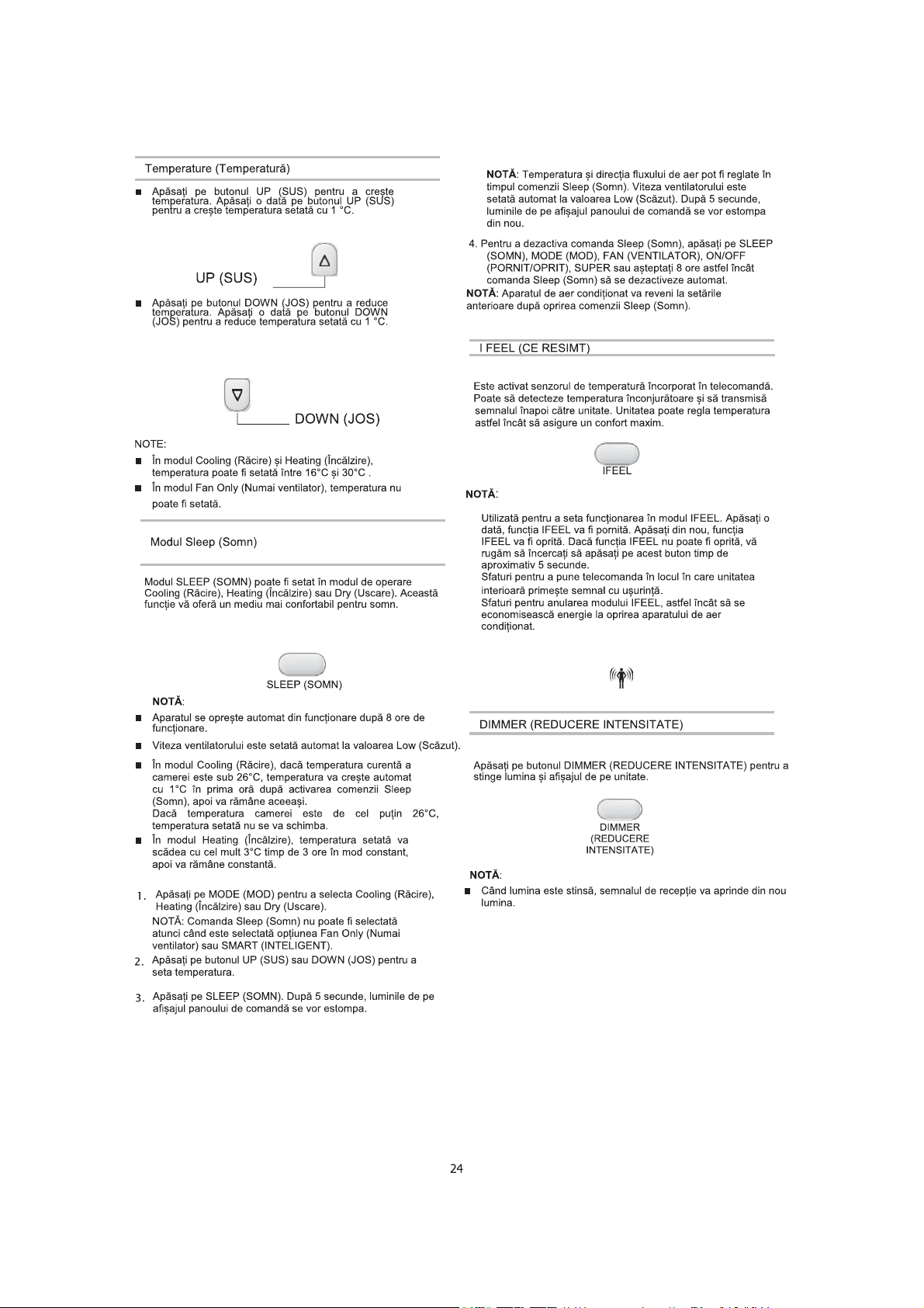
Temperature
■ Press the UP button to raise the temperature. Press
the UP button once to increase the set temperature
by 1°C.
UP
■ Press the DOWN button to lower the temperature.
Press the DOWN button once to decrease the set
temperature by 1°C.
DOWN
NOTES:
■ In the Cooling and Heating mode, the temperature can be
set between 16 C and 30 C.°°
■ In Fan Only mode,the temperature cannot be set.
Sleep mode
SLEEP mode can be set in Cooling, Heating or Dry operation
mode. This function gives you a more comfortable environment
for sleep.
NOTE:
The temperature and airflow direction may be adjusted
during Sleep control. The fan speed is automatically set to
Low speed. After 5 seconds, the lights on the control panel
display will dim again.
4. To turn off Sleep control, press SLEEP, MODE, FAN,
ON/OFF,SUPER or wait 8 hours for Sleep control to turn off
automatically.
NOTE:
The air conditioner will return to previous settings after
Sleep control is turned off.
I FEEL
The temperature sensor built in remote controller is activated.
It can sense its surrounding temperature, and transmit the signal
back the unit. the unit can adjust the temperature so as to provide
maximum comfort.
IFEEL
NOTE:
Used to set IFEEL mode operation. Press it once, the IFEEL
function will be started. Press it again, the IFEEL function
will be shut off.If the IFEEL function can't be shut off, please
try to press this button about 5 seconds.
Advice to put the remote controller in the place where the
indoor unit receive signal easily.
Advice to cancel the IFEEL mode so as to save energy
when stopping the air conditioner.
SLEEP
NOTE:
The appliance will stop operation automatically after operating
■
for 8 hours.
■
Fan speed is automatically set at low speed.
■ In the Cooling mode, if the current room temperature is
below , the 26°C temperature will automatically increase
1°C during the first hour after Sleep control is activated,
then remain the same.
If room temperature is 26 or above,set temperature will
°C
not change.
■ In Heating mode, set temperature will decrease by 3°C
at most for 3 hours constantly, then keeps
Press MODE to select Cooling, Heating or Dry.
1.
steady.
NOTE: Sleep control cannot be selected when Fan Only
or SMART is selected.
2. Press the UP or DOWN button to set the temperature.
3. Press SLEEP. After 5 seconds, the lights on the control panel
display will dim.
DIMMER
Press the DIMMER button to turn off the light and the display in the
unit.
DIMMER
NOTE:
When the light is off, receive signal will turn on the light again.
■
2
Page 27
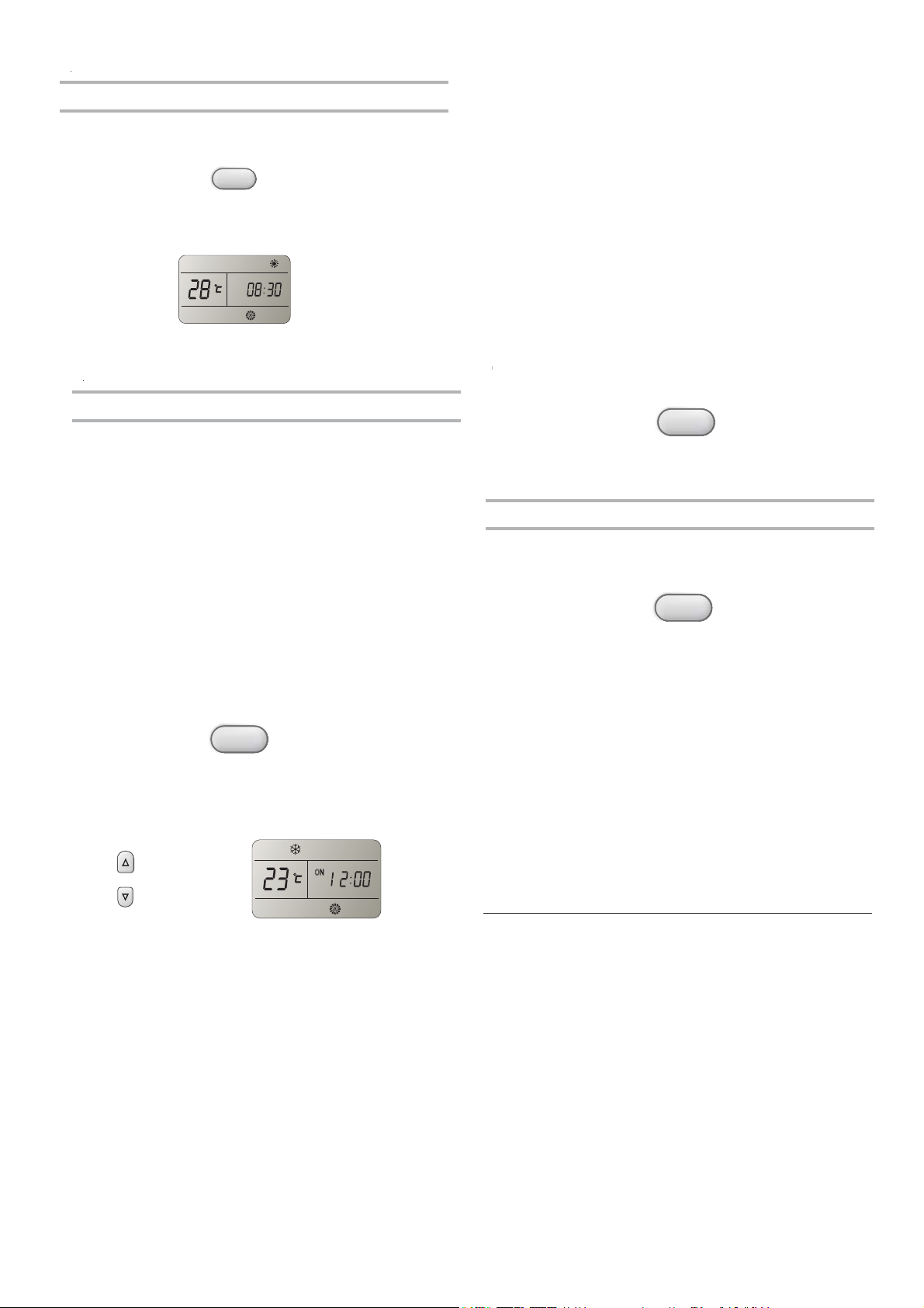
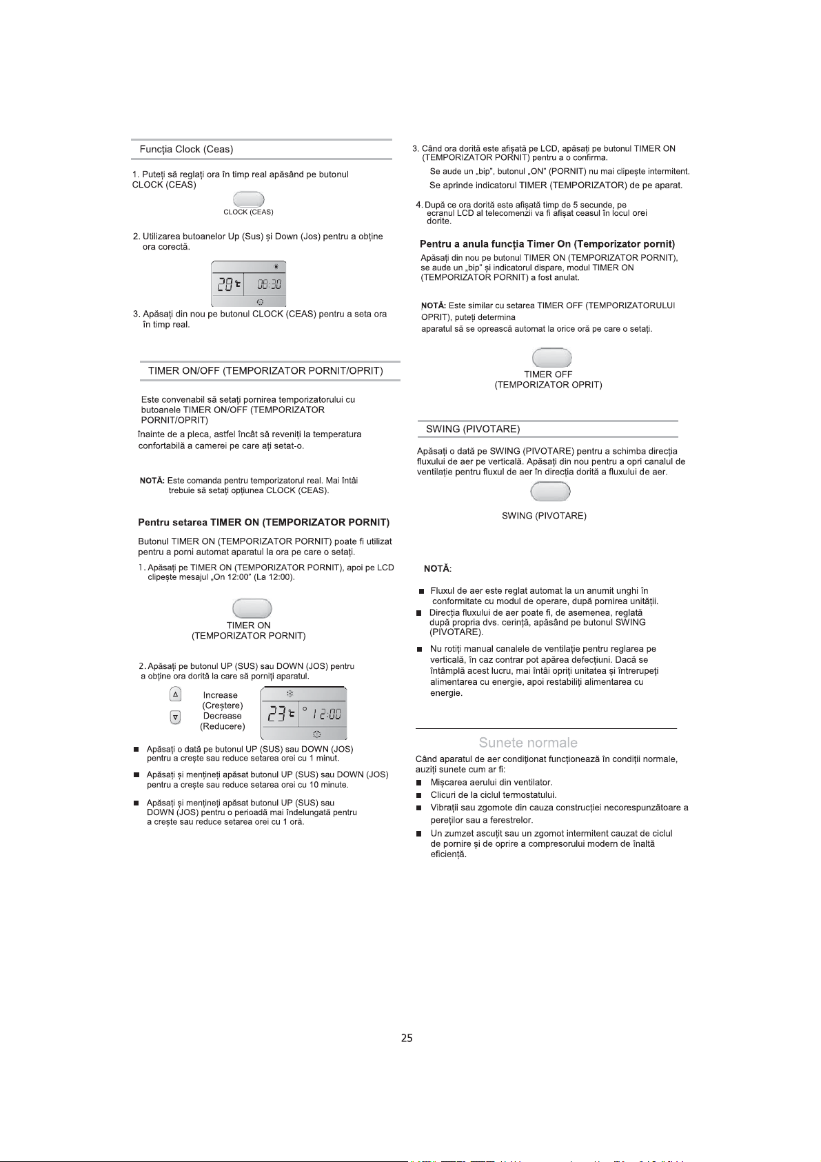
Clock function
1. You can or adjust the real time by pressing CLOCK button
3. When your desired time displayed on LCD, press the TIMER ON
button to confirm it.
“Beep” can be heard,
A
“ON” stops flashing.
The TIMER indicator on the appliance lights up.
CLOCK
2. Using the Up and Down buttons to get the correct time.
3. Press CLOCK button again the real time is set.
TIMER ON/OFF
It is convenient to set the timer on with TIMER ON/OFF buttons
before you leave so that you will come back to the comfortable
room temperature you set.
NOTE:
It is real timer control. you should set the CLOCK first.
To TIMER ON
TIMER ON button can be used to turn on the unit automatically at
the time you set.
1. Press TIMER ON, Then "On 12:00" flashes on the LCD.
TIMER ON
2. Press the UP or DOWN button to get your desired time
to turn on the appliance.
4. After your desired time displayed for
will be displayed on the LCD of remote controller instead of
5 seconds, the clock
the desired time.
To cancel Timer On
Press TIMER ON button again, a "beep" can be heard and the
indicator disappears, the TIMER ON mode has been canceled.
It is similar to set TIMER OFF, you can make
NOTE:
the appliance unit switch off automatically at the
TIMER OFF
SWING
Press SWING once to change vertical airflow direction. Press
again to stop airflow louver at desired airflow direction.
SWING
NOTE:
Airflow is automatically adjusted to a certain angle in accordance
■
with the operation mode after turning on the unit.
The direction of airflow can be also adjusted to your own
■
requirement by pressing the SWING button.
■
Do not turn the vertical adjustment louvers manually,
otherwise malfunctions m ay occu r. if that h appens, turn
off the unit first and cut off the power supply, then
restore power supply again.
time you set.
Increase
ON
Decrease
■
Press the UP or DOWN button once to increase or
decrease the time setting by 1minute.
■
Press and hold the UP or DOWN button for 2
seconds to increase or decrease the time setting by 10 minutes.
■
Press and hold the UP or DOWN button for a longer time
to increase or decrease the time setting by 1 hour.
Normal Sounds
When your air conditioner is operating normally, you may hear
sounds such as:
■ Air movement from the fan.
■ Clicks from the thermostat cycle.
■ Vibrations or noise due to poor wall or window construction.
■ A high-pitched hum or pulsating noise caused by the modern
high-efficiency compressor cycling on and off.
2
Page 28
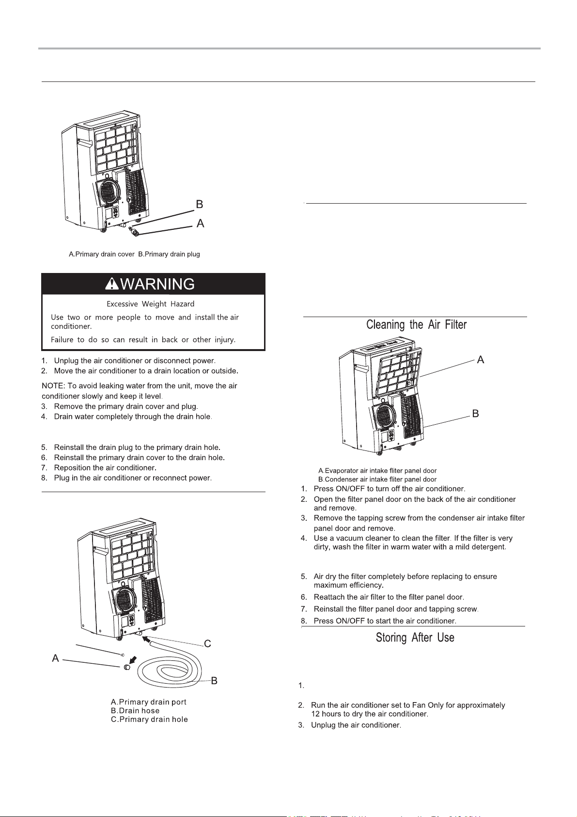
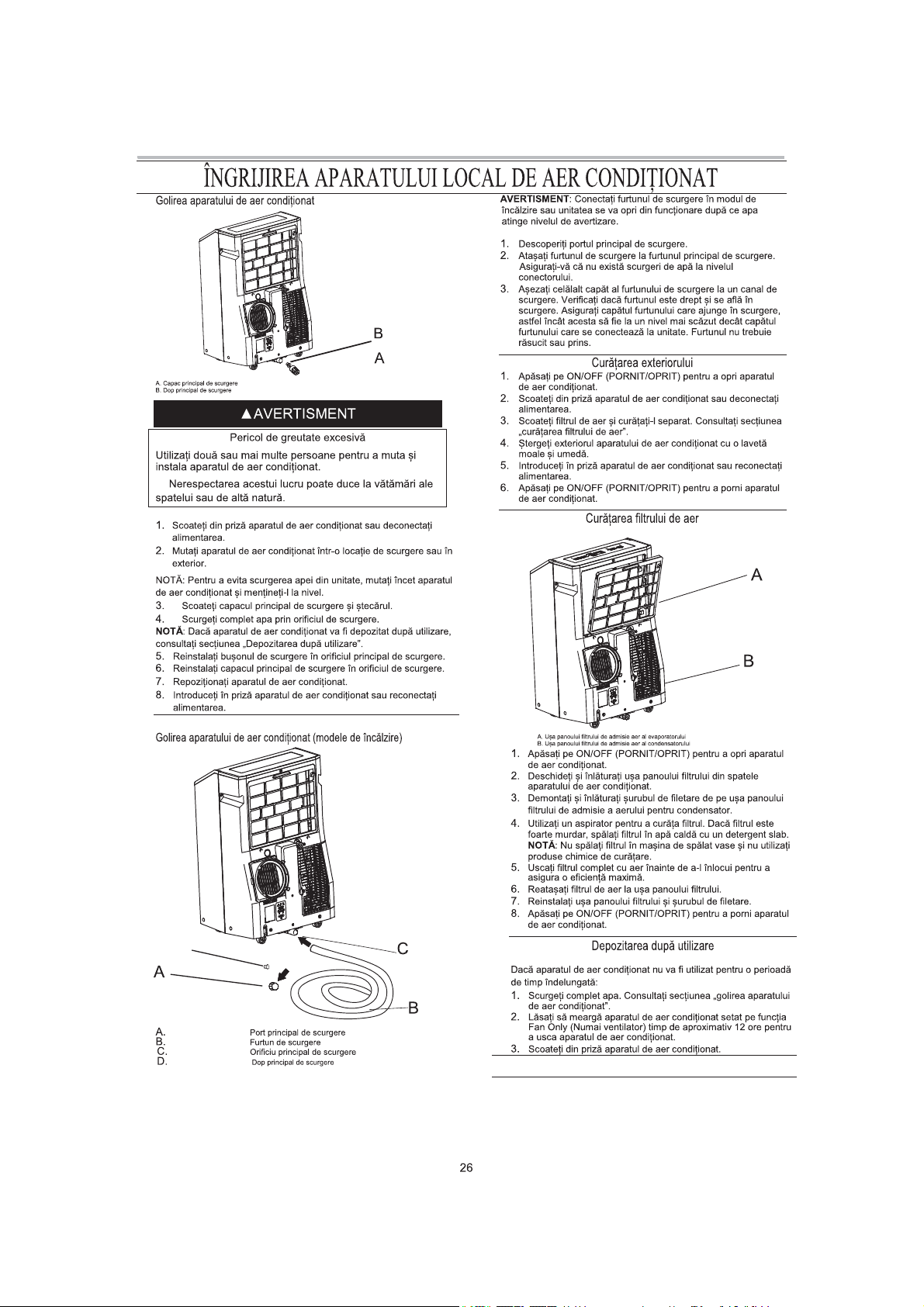
LOCAL AIR CONDITIONER CARE
Draining the Air Conditioner
WARNING: Please connect the drain hose on heating
mode, or the unit will stop running after the water the water
reaches warning level.
1. Uncover the primary drain port.
2. Atta ch the drain hose to the primary drain hose.
Make sure the connector has no water leak.
3. Place the other end of drain hose into a ou tfall . Check t o
see that the hose lies fl at and is i n the dra in. Mak e sure
the hose end that goes to t he drai n is on a lower level
than the hose end that connects to the unit. The hose
should not be kinked or pinched.
Cleaning the Outside
1. Press ON/OFF to turn off the air conditioner.
2. Unplug the air conditioner or disconnect power.
3. Remove the air filter and clean separately. See "cleaning the
Air Filter ."
4. Wipe the outside of the air conditioner with a soft, damp
cloth.
5. Plug in the air conditioner or reconnect power.
6.
Press ON/OFF to start the air conditioner.
NOTE: If the air conditioner will be stored after use, see
"Storing After Use".
Draining the Air Conditioner(Heating models)
D
NOTE: Do not wash the filter in the dishwasher or use any
chemical cleaners.
If the air conditioner will not be used for an extended
period of time:
Drain the water completely. See "draining the
Conditioner ."
Air
D.Primary drain plug
2
Page 29
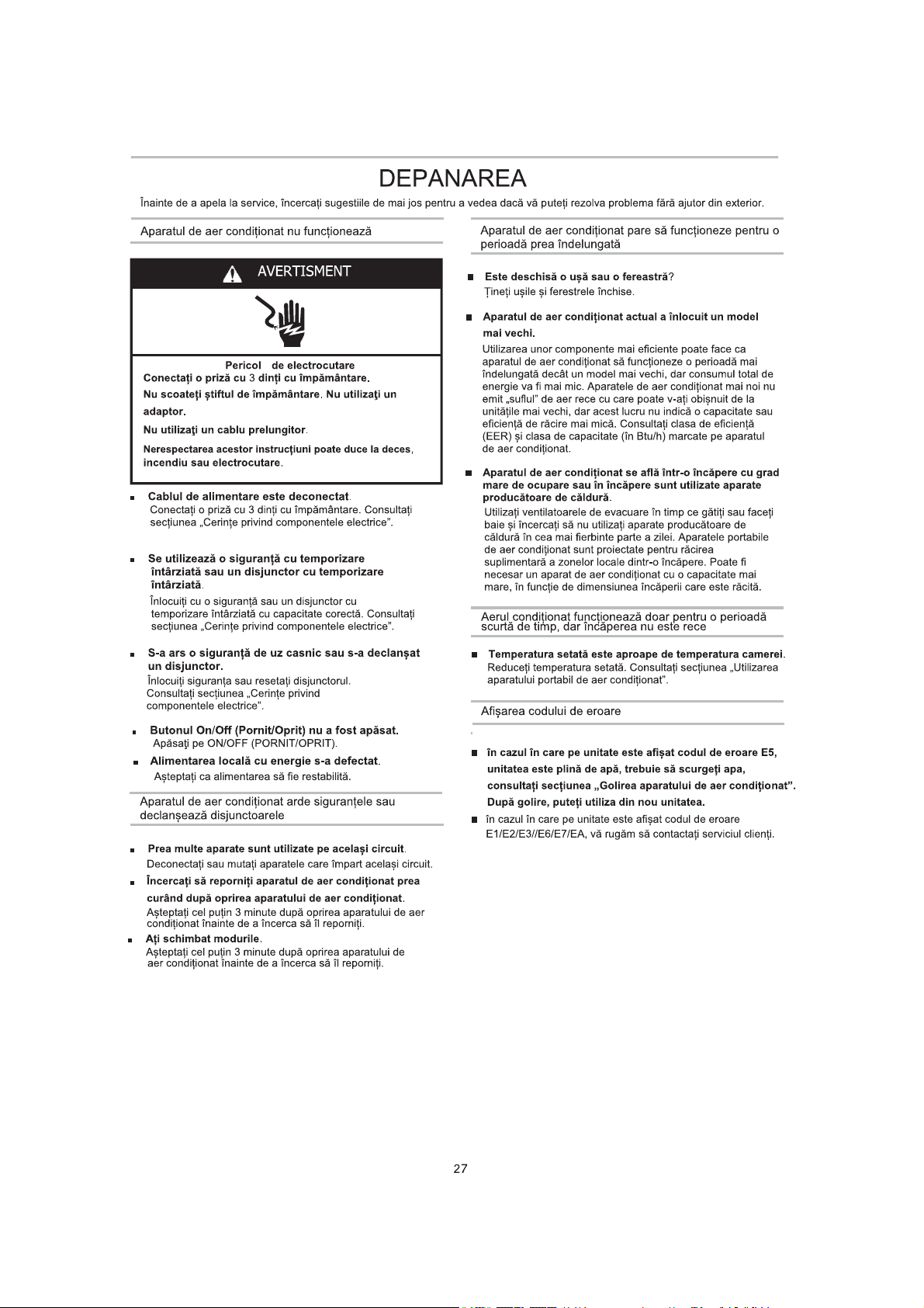
TROUBLESHOOTING
Before calling for service, try the sugge
stions below to see whether you can so
Air conditioner will not operate
WARNING
Electrical Shock Hazard
Plug into a grounded 3 prong outlet.
Do not remove ground prong.
Do not use an adapter.
Do not use an extension cord.
Failure to follow these instructions can result in death,
fire, or electrical shock.
■
The power supply cord is unplugged.
Plug into a grounded
Requirements.”
■ Time-delay fuse or circuit breaker of the wrong
capacity is being used.
Replace with a time-delay fuse or circuit breaker of the
correct capacity. See " electrical
WARNING
3 prong outlet. See " electrical
Requirements”.
lve your problem without outside help.
Air conditioner seems to run too much
■ Is there a door or window open?
Keep doors and windows
■ The current air conditioner replaced an older model.
The use of more efficient components may cause the air
conditioner to run longer than an older model, but the total
energy consumption will be less. Newer air conditioners do
not emit the “ blast” of cold air you may be accustomed to
from older units, but this is not an indication of lesser cooling
capacity or efficiency. Refer to the efficiency rating (EER) and
capacity rating (in Btu/h) marked on the air conditioner.
■ The air conditioner is in a heavily occupied room, or heat-
producing appliances are in use in the room.
Use exhaust vent fans while cooking or bathing and try not
to use heat-producing appliances during the hottest part of
the day. air conditioners are designed as
supplemental cooling to local areas within a room. A higher
capacity air conditioner may be required, depending on the
size of the room being cooled.
Portable
closed.
Air conditioner runs for a short time only, but room is not
cool
■ Set temperature is close to room temperature.
Lower set temperature. See " P Air Conditioner Use ”.ortable
■ A household fuse has blown, or a circuit breaker has
tripped.
Replace the fuse, or reset the circuit breaker. See
“Electrical Requirements”.
■ The On/Off button has not been pressed.
Press ON/OFF.
■
The power has failed.local
Wait for power to be restored.
Air conditioner blows fuses or trips circuit breakers
■ To o many appliances are being used on the same circuit.
Unplug or relocate appliances that share the same circuit.
■ Yo u are trying to restart the air conditioner too soon after
turning off air conditioner.
Wait at least 3 minutes after
trying to restart the air conditioner.
■ Yo u have changed modes.
Wait at least 3 minutes after turning off air conditioner
before trying to restart the air conditioner.
turning off air conditioner before
Display error code
■ if the unit display error code E5, it is water full in the unit,
you should drain the water, see “Draining the air
conditioner”. After draining, you can operate the unit again.
■
if the unit display error code E1/E2/E3//E6/E7/EA, please contact
customer service.
2
Page 30

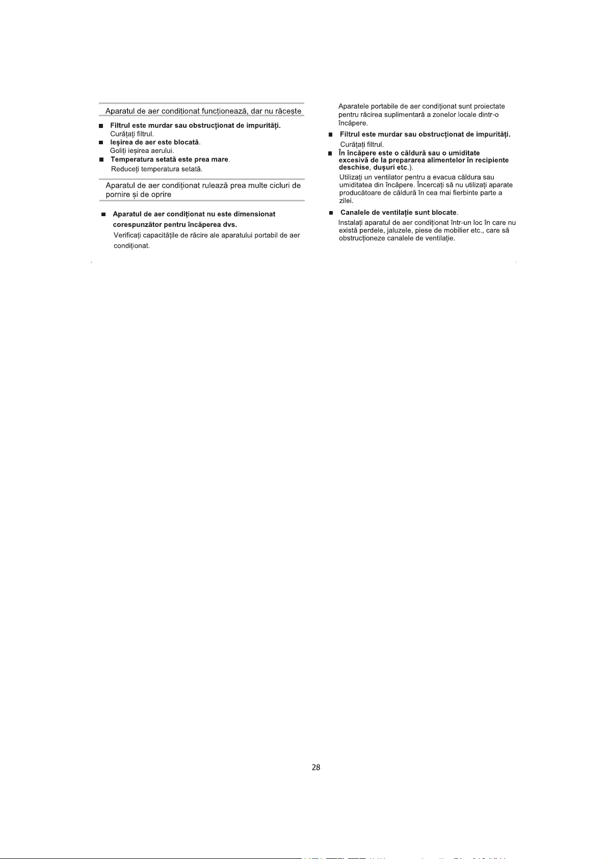
Air conditioner runs, but does not cool
■ The filter is dirty or obstructed by debris.
Clean the filter.
■ Air outlet is blocked.
Clear air outlet.
■ Set temperature is too high.
Lower set temperature.
Air conditioner cycles on and off too much
■ The air conditioner is not properly sized for your room.
Check the cooling capabilities of your portable air conditioner.
Portable air conditioners are designed as supplemental
cooling to local areas within a room.
■ The filter is dirty or obstructed by debris.
Clean the filter.
■
There is excessive heat or moisture open container
cooking, showers, etc.) in the room.
Use a fan to exhaust heat or moisture from the room.
Try not to use heat-producing appliances during the
hottest part of the day.
■ The louvers are blocked.
Install the air conditioner in a location where the louvers
are free from curtains, blinds, furniture, etc.
2
Page 31
Page 32

Page 33
Page 34
Page 35
Page 36
Page 37
Page 38
Page 39
Page 40
Page 41
$3&*16P, $3+*16P
$3&*46P, $3+*46P
$3&*167$9, $3+*167$9
$3&*467$9$3+*467$9
Page 42
Page 43
Page 44
TIMER ON TIMER OFF CLOCK
,'(17,),&$5($3Ă5܉,/25&20321(17(
OO
NN
FF
OO
FF
ON/O
FF
MODE FAN
SWING SLEEP
SMART
IFEEL DIMMER
SUPER
Page 45

&(5,1܉(3(1758,167$/$5(
3ăU܊L܈LXQHOWHQHFHVDUH
$GXQD܊LSăU܊LOH܈LXQHOWHOHQHFHVDUHvQDLQWHGHDvQFHSHLQVWDODUHD&LWL܊LLQVWUXF܊LXQLOHGHPDLMRV
܈LDVLJXUD܊LYăFăDYH܊L܈LXQHOWHOHLQGLFDWHPDLMRVQHLQFOXVHvQSDFKHWXOSURGXVXOXL
8QHOWHQHFHVDUH
܇XUXEHOQL܊ă3KLOLSV)RDUIHFă&UHLRQ0D܈LQăGHJăXULWIăUăILUFXYkUIGH´
3ăU܊LIXUQL]DWH
8UPDWRDUHOHSăU܊LSLHVHVXQWIXUQL]DWHvPSUHXQăFXDSDUDWXOGHDHUFRQGL܊LRQDW
Part
'HVFULHUH
A.,]RODWRUGHVSXPă
B.&XSODM
C.)XUWXQGHHYDFXDUHIOH[LELO
$GDSWRUGHHYDFXDUHSHQWUXIHUHDVWUă
D.
E.1LWXUL
F.6XUXEXUL
G.&OHPă
H.
3DUWHH[WHULRDUăFXOLVDQWăFXYHQWLOD܊LH
I.3DUWHFXOLVDQWăLQWHULRDUăVFXUWă
J.3DUWHFXOLVDQWăLQWHULRDUă
K.3DUWHFXOLVDQWăH[WHULRDUă
L.,]RODWRUOXQJGHVSXPă
M.,]RODWRUGHVSXPăVFXUW
)XUWXQGHHYDFXDUHSHQWUXPRGHOHOHFXSRPSăGHFăOGXUă
N.
O.
&OHPăSHQWUXIXUWXQXOGHHYDFXDUHSHQWUXPRGHOHOHFXSRPSăGHFăOGXUă
P.7HOHFRPDQGă
Q.%DWHULLVWDQGDUG$$$YRO܊L
&DQWLWDWH
1 EXF
1 EXF
1 EXF
1 EXF
4 EXF
4 EXF
2 EXF
1 EXF
1 EXF
1 EXF
1 EXF
2 EXF
2 EXF
1 EXF
1 EXF
1 EXF
2 EXF
Note
%$7(5,,)Ă5Ă0(5&85³683(5+($9<'87<´580$$$9
$),)2/26,7(3Æ1Ă/$'$7$'(&2'/81Ă$1/$3$57($
,1)(5,2$5Ă
1XDPHVWHFD܊LEDWHULLOHYHFKLFXFHOHQRL1XDPHQVWHFD܊LEDWHULL
DOFDOLQHFXEDWHULLVWDQGDUG&DUERQ=LQFVDXFXEDWHULL
UHvQFăUFDELOH1FKHO&DGPLX
18$581&$܉,%$7(5,,/(Ì1)2&$&(67($327(;3/2'$6$8327/8$)2&.
1XvQJKL܊LWL
%DWHULLOH3RWFDX]DVXI2FDUHGDFăVXQWÌQJKLWLWHGHFRSLL
%DWHULLOHQHUHÌQFăUFDELOHQXWUHEXLHUHvQFăUFDWH
%DWHULLOHWHUPLQDWHGHVFăUFDWHWUHEXLHVFRDVHGLQSURGXV
Page 46
Page 47
Page 48
1.0XWD܊LDSDUDWXOGHDHUFRQGL܊LRQDWvQORFD܊LDGRULWă9H]L
VHF܊LXQHD³&HULQ܊HUHIHULWRDUHODDPSODVDUH´
3UHJăWLUHDSHQWUXDVDPEODUHDIXUWXQXOXLGHHYDFXDUH
$SăVD܊LFXSODMXO܈LDGDSWRUXOGHIHUHVDWUăvQIXUWXQXOGH
HYDFXDUH$PEHOHDXFOHPHGHIL[DUHFDUHVHSRWULYHVFLQSăU܊LOH
FRUHVSXQ]ăWRDUHDOHFHOXLODOWVXEDQVDPEOX
)XUWXQGHHYDFXDUHIOH[LELO
&XSODM
$VDPEODUHDIXUWXQXOXLGHHYDFXDUH
,QWURGXFH܊LFXSODMXOvQIDQWDGLQVSDWHOHDSDUDWXOXLGHDHU
FRQGLWLRQDW
*OLVD܊LvQMRVSHQWUXDIL[DIXUWXQXOvQORFD܈
$GDSWRUSHQWUXHYDFXDUHOD
IHUHDVWUă
A
B
C
$,QWUDUHDHUFăWUHHYDSRUDWRU
%&XSODM
&)XUWXQGHHYDFXDUHIOH[LELO
',QWUDUHDHUFăWUHFRQGHQVDWRU
D
Page 49
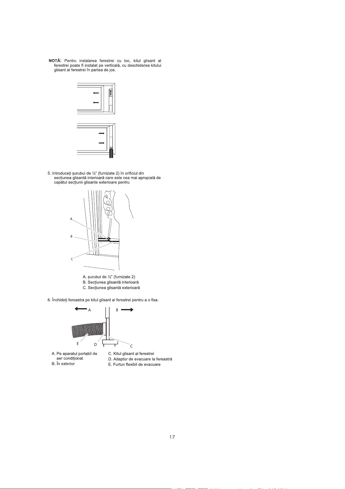
Page 50
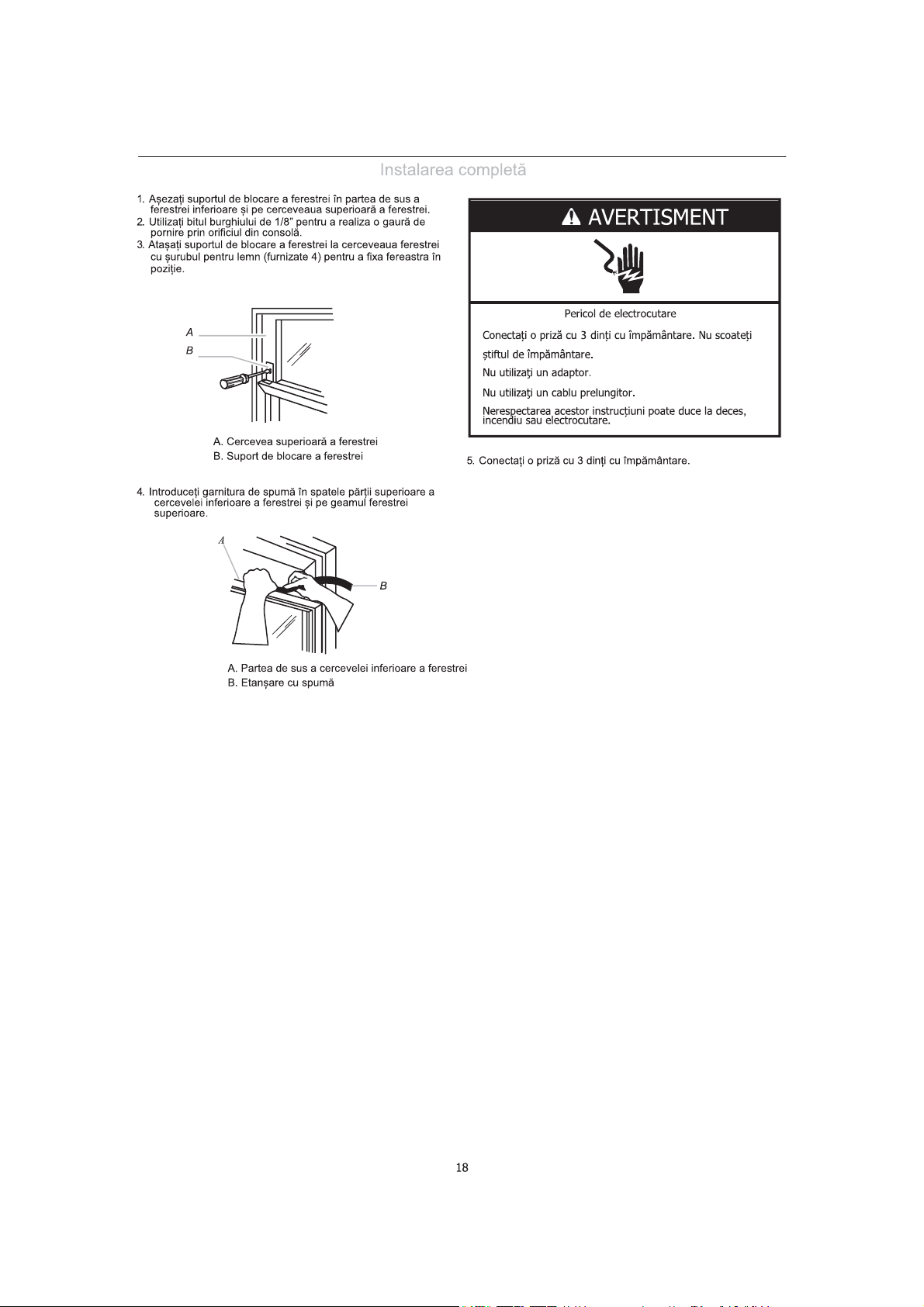
Page 51
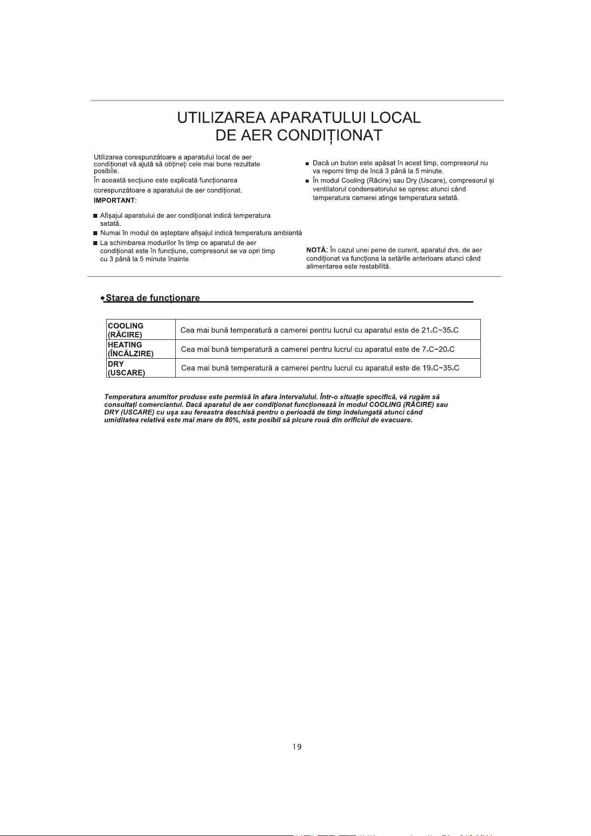
Page 52
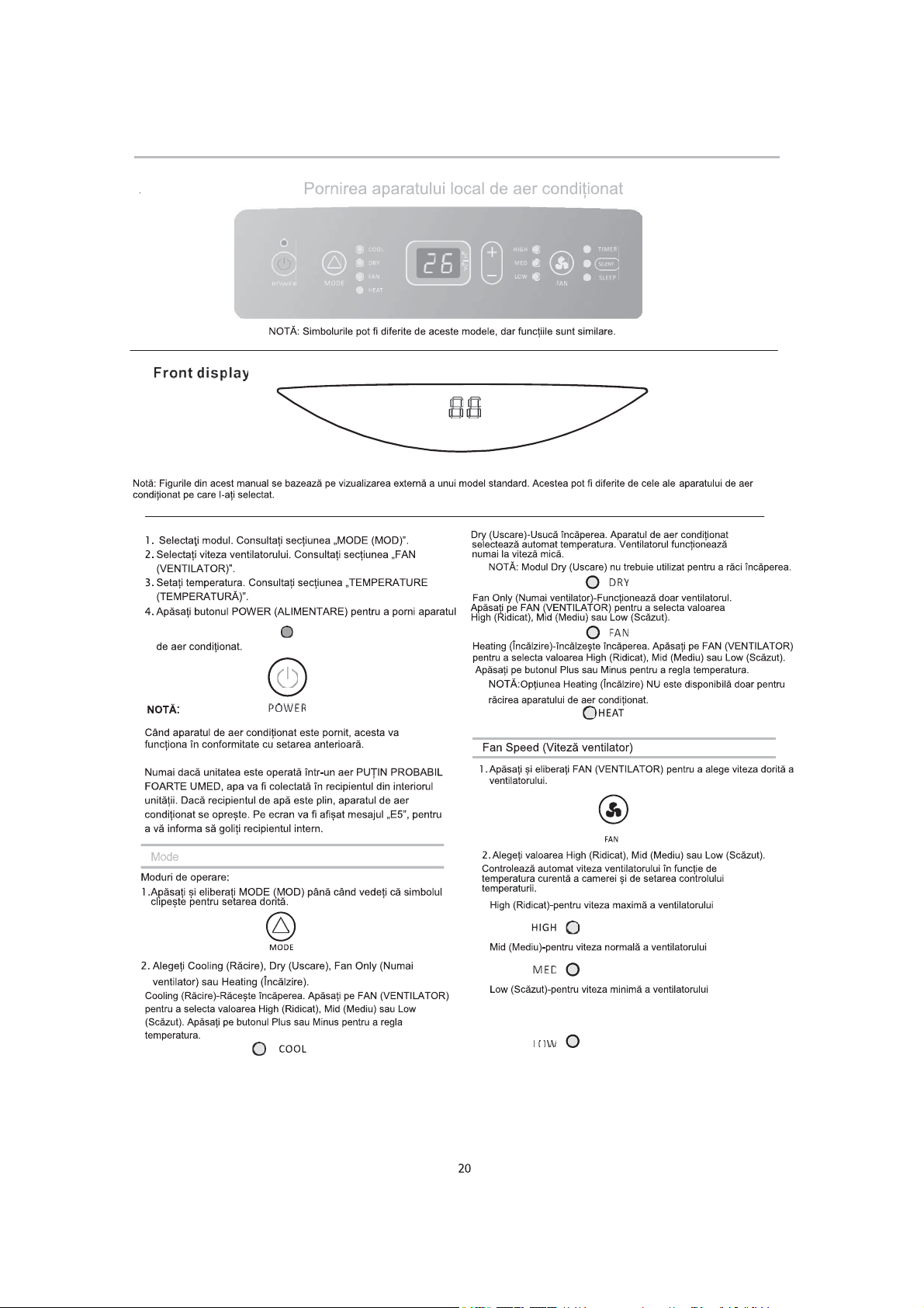
Page 53
Page 54
Page 55
Page 56
Page 57
Page 58
D
Page 59
Page 60
Page 61
Page 62
Page 63
Page 64
Page 65
Page 66
Page 67
Page 68
Page 69
Page 70
Page 71
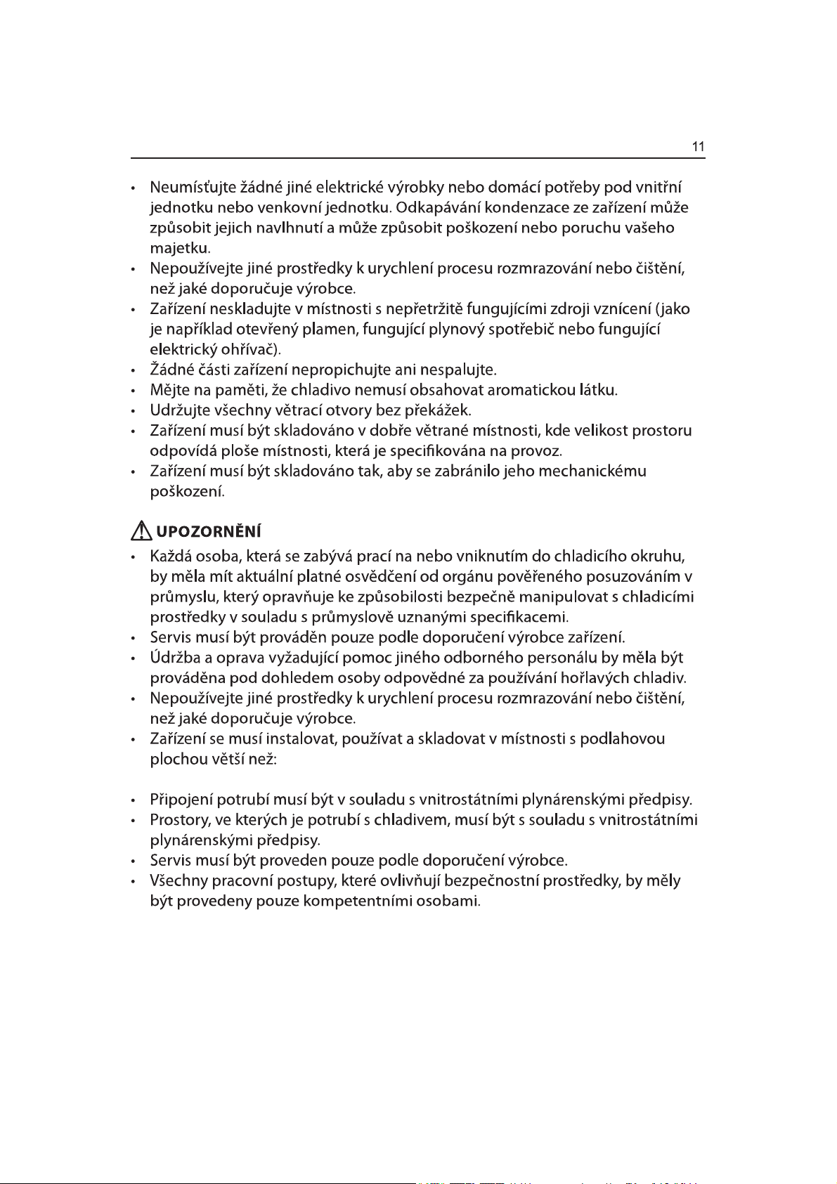
$3&*16P$3+*16P
$3&*46P$3+*46P
Page 72
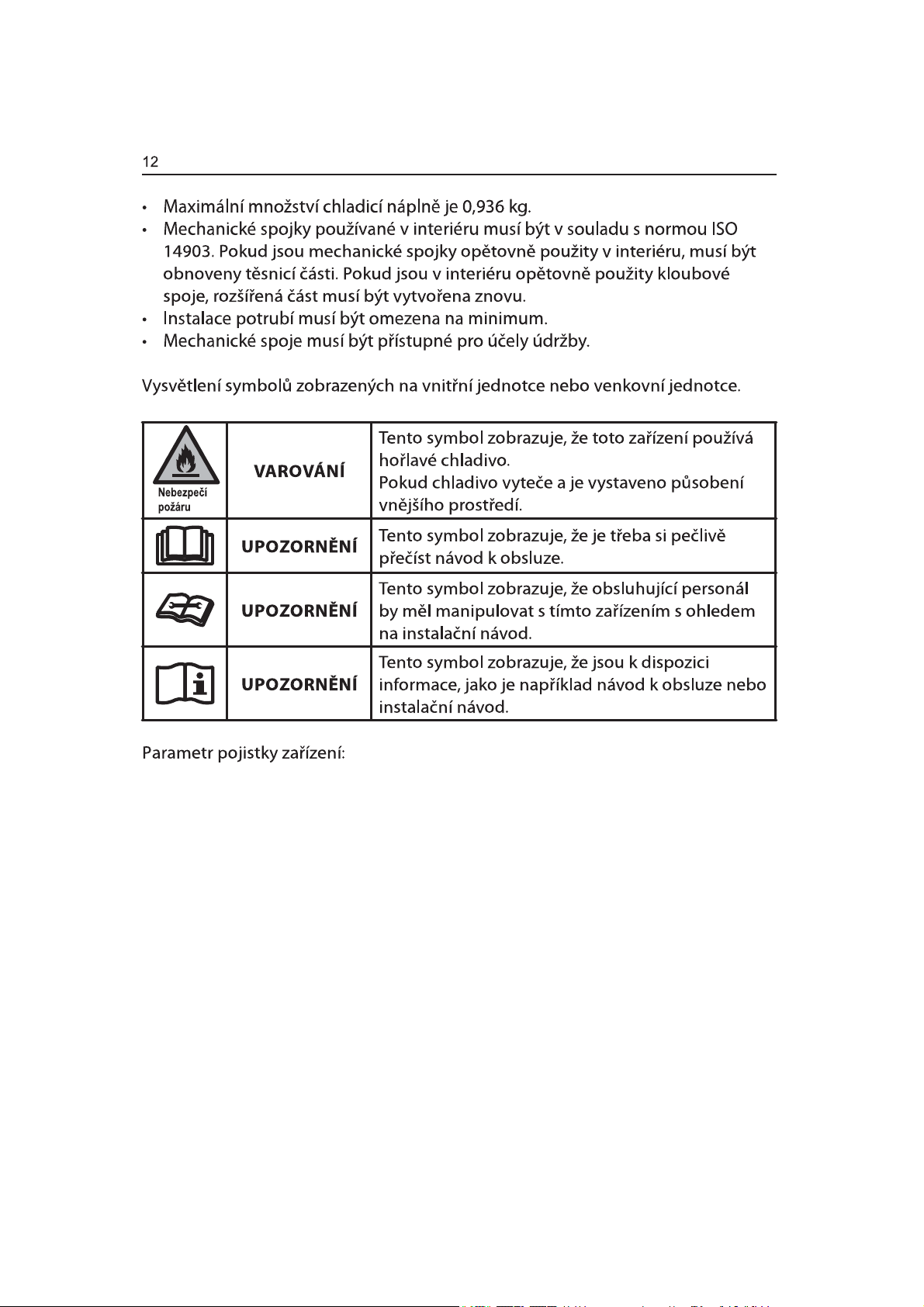
$3&*167$9, $3+*167$9
$3&*467$9$3+*467$9
Page 73
FF
OO
OO
NN
FF
ON/OFF
MODE
SWING
FAN
SMART
SLEEP
TIMER ONTIMER OFFCLOCK
IFEEL
SUPER
DIMMER
1DSiMHFtNDEHO
Page 74
Page 75
1iVWURMHDGtO\
3ĜHG]DKiMHQtPLQVWDODFHVKURPiåGČWHSRWĜHEQpQiVWURMHDGtO\3ĜHþWČWHVLDGRGUåXMWHSRN\Q\
GRGDQpVHYãHPL]GHXYHGHQêPLQiVWURML
3RWĜHEQpQiVWURMH
.ĜtåRYêãURXERYiN
1ĤåN\
7XåND
$NXPXOiWRURYiYUWDþNDDYUWiN
'RGiYDQpGtO\
6SĜHQRVQRXNOLPDWL]DFtMVRXGRGiYiQ\QiVOHGXMtFtGtO\
ýiVW
3RSLV
A.3ČQRYpWČVQČQt
B.6SRMND
C.3UXåQiYêIXNRYiKDGLFH
D.2NHQQtYêIXNRYêDGDSWpU
E.1êW\
F.âURXE\
G.'UåiN]iPNXRNQD
9QČMãtþiVWMH]GFHVYHQWLODþQtPRWYRUHP
H.
I.9QLWĜQtSRVXYQiþiVW±NUiWNi
J.YQLWĜQtSRVXYQiþiVW
K.9QČMãtþiVWMH]GFH
L.3ČQRYpWČVQČQt±GORXKp
M.3ČQRYpWČVQČQt±NUiWNp
9\SRXãWČFtKDGLFHPRGHO\WHSHOQêFKþHUSDGHO
N.
O.
6SRQDY\SRXãWČFtKDGLFHPRGHO\WHSHOQêFKþHUSDGHO
P.'iONRYpRYOiGiQt
Q.6WDQGDUGQtEDWHULH$$$9
3R]QiPND
9(/,.267$$$90(5&85<)5((683(5
+($9<'87<580
1(-/e3(328äË73ě(''$729é0.Ï'(00ċ6Ë&
52. %DWHULHPĤåHSĜLVSRONQXWt
89('(1é0'2/(
1HPtFKHMWHVWDUpDQRYpEDWHULH1HPtFKHMWHDONDOLFNp
EDWHULH 1HQDEtMHFtEDWHULHVHQHVPt
6WDQGDUGQtXKOtNRYp±]LQNRYpDQLGREtMHFtQLNORYp
GREtMHW
NDGPLRYpEDWHULH
0QRåVWYt
1 NV
1 NV
1 NV
1 NV
4 NV
4 NV
2 NV
1 NV
1 NV
1 NV
1 NV
2 NV
2 NV
1 NV
1 NV
1 NV
2 NV
3R]RUQDSRåLWt
%DWHULHPĤåH]SĤVRELWGXVHQtSĜL
VSRONXGČWPL
1HQDEtMHFtEDWHULHVHQHVPtGREtMHW
9\þHUSDQpEDWHULHPXVtEêWY\MPXW\]
YêURENX
1(9+$=8-7(%$7(5,('22+1ċ%$7(5,(02+28(;3/2'29$71(%29<7e&7
Page 76
Page 77
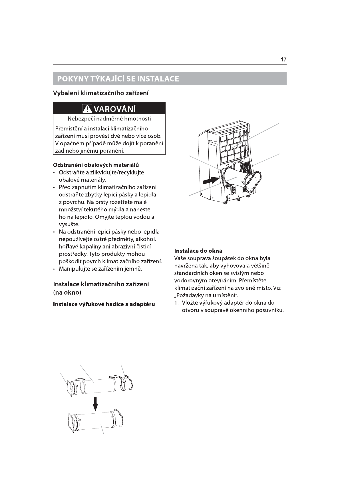
9ORåWHDWUDSXVSRMN\GRRWYRUXQD]DGQt
VWUDQČNOLPDWL]DFH
3RVXQXWtPGROĤ]DMLVWČWHKDGLFLQDPtVWČ
A
8PtVWČWHNOLPDWL]DþQtMHGQRWNXQD]YROHQp
PtVWRYL]3RåDGDYN\QDXPtVWČQt
3ĜtSUDYDVHVWDY\YêIXNRYpKDGLFH
=DVXĖWHVSRMNXDRNHQQtYêIXNRYêDGDSWpU
GRRKHEQpYêIXNRYpKDGLFH6SRMNDLRNHQQt
YêIXNRYêDGDSWpUPDMtLQWHJURYDQpVYRUN\
NWHUpVHQDFYDNQRXQDKDGLFL
VSRMND
IOH[LELOQtYêIXNRYp
KDGLFH
RNHQQtYêIXNRYêDGDSWpU
B
C
$6iQtY]GXFKXGRYêSDUQtNX
%6OHSiVSRMND
&3UXåQiYêIXNRYiKDGLFH
'3ĜtYRGY]GXFKXNHNRQGHQ]iWRUX
D
VHVWDYDYêIXNRYpKDGLFH
Page 78
Page 79
Page 80
Page 81
Page 82
Page 83
Page 84
Page 85
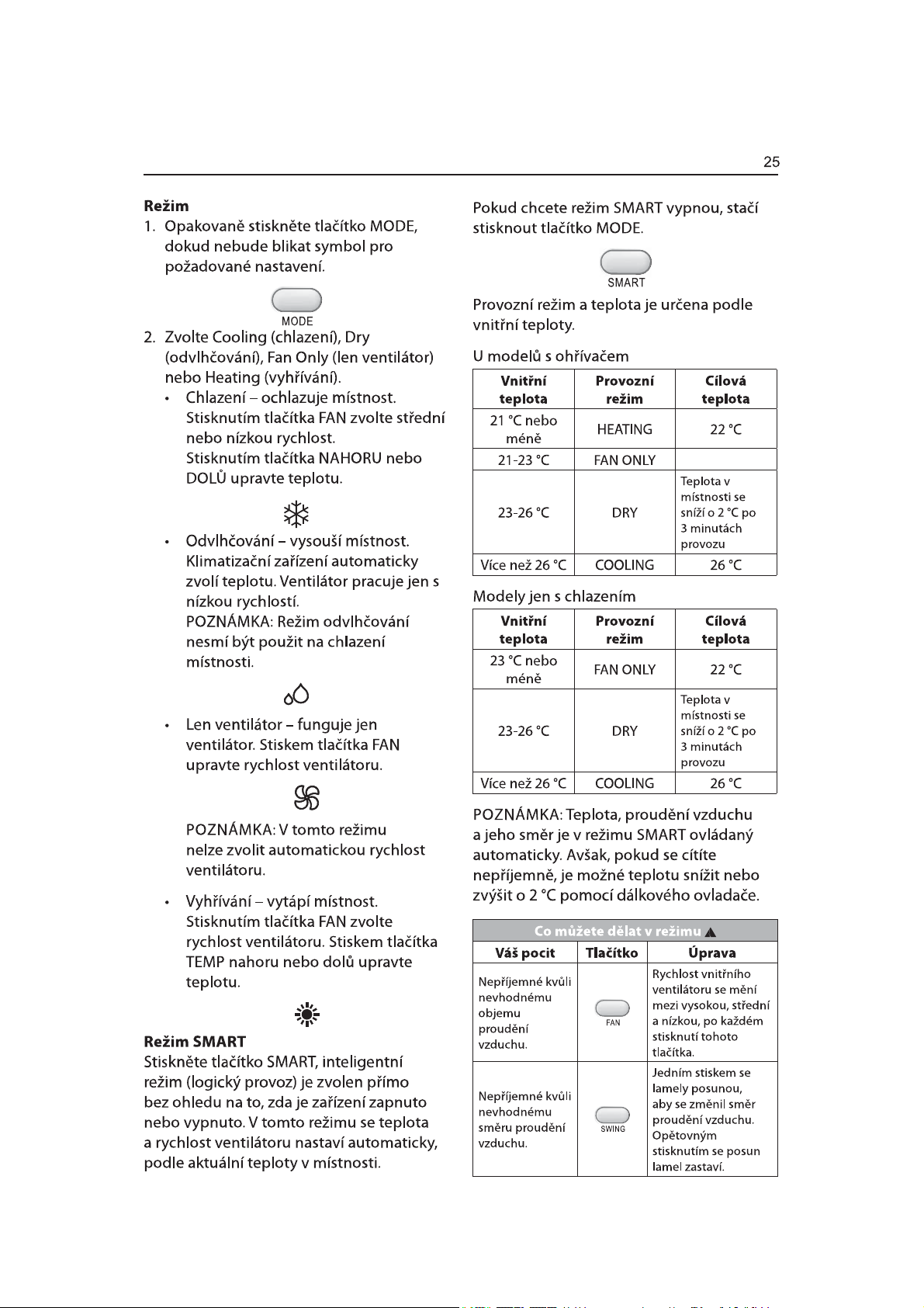
Page 86
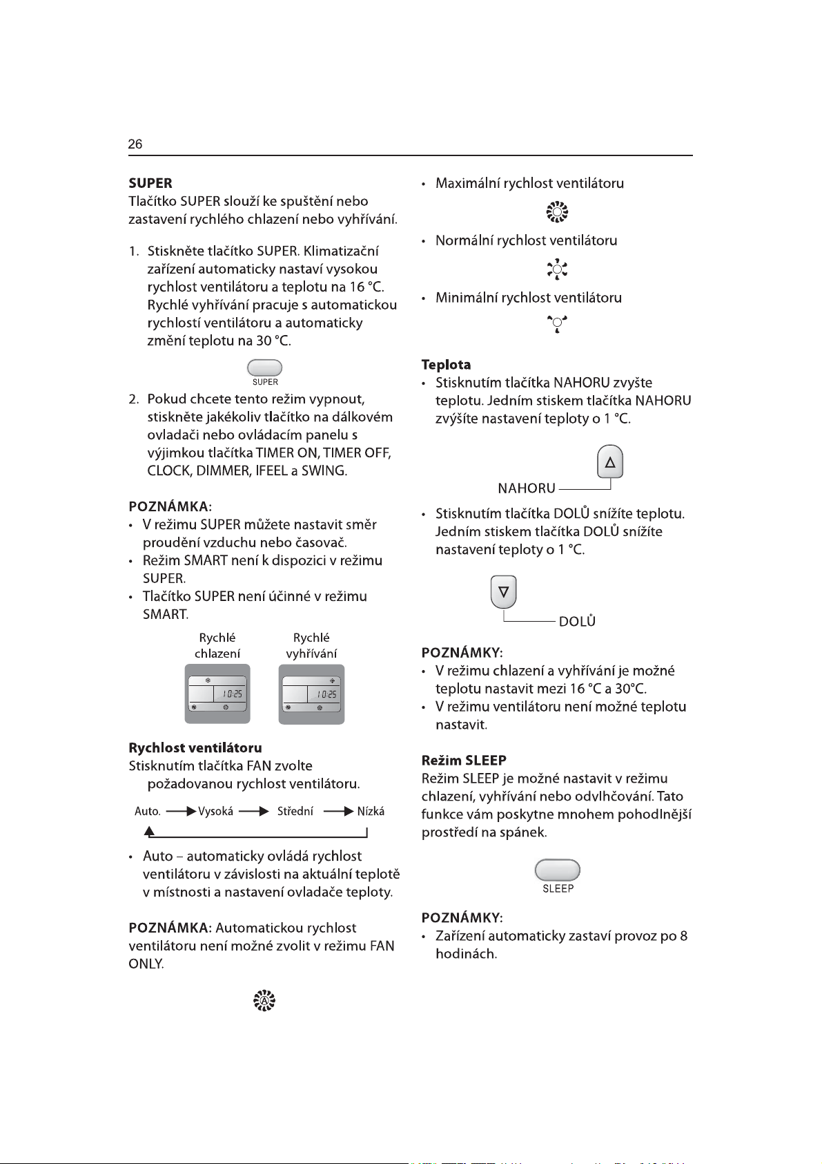
Page 87
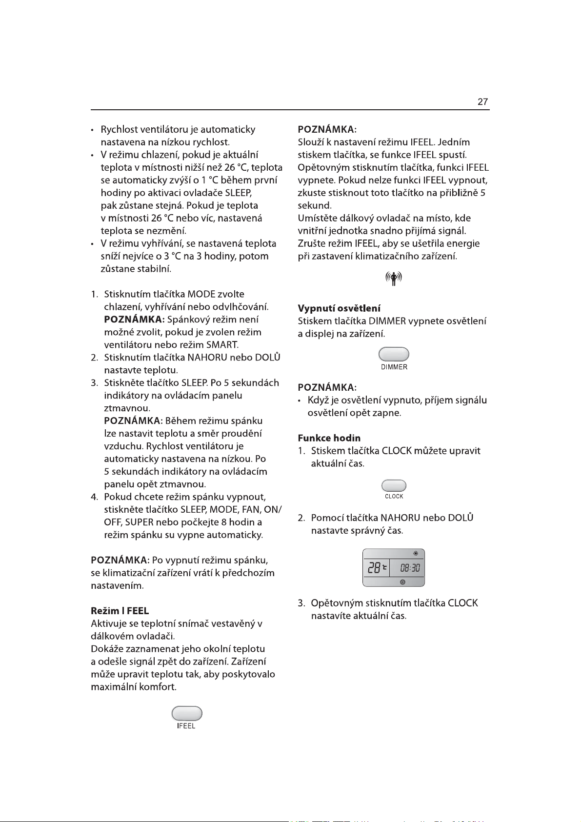
Page 88
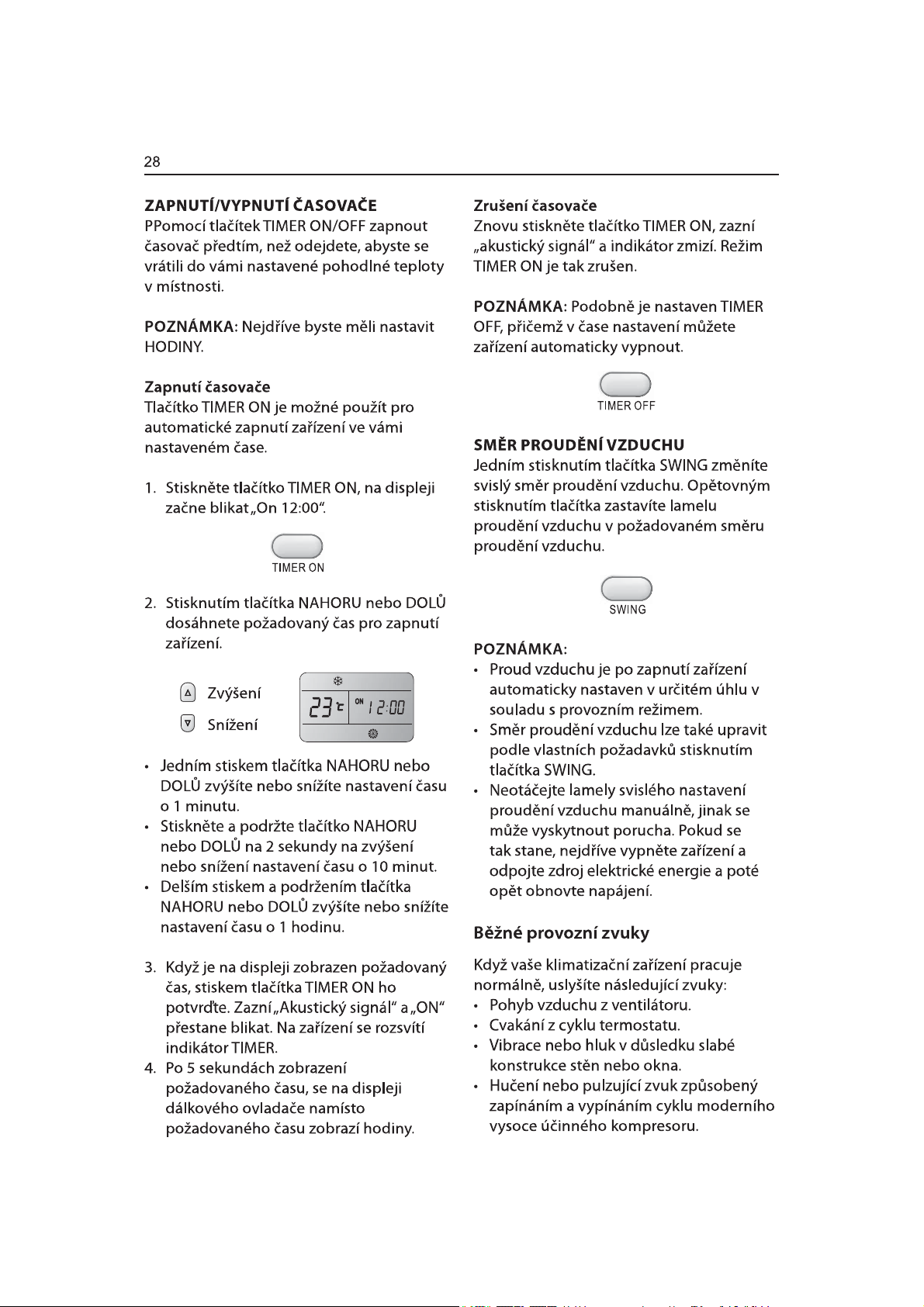
Page 89
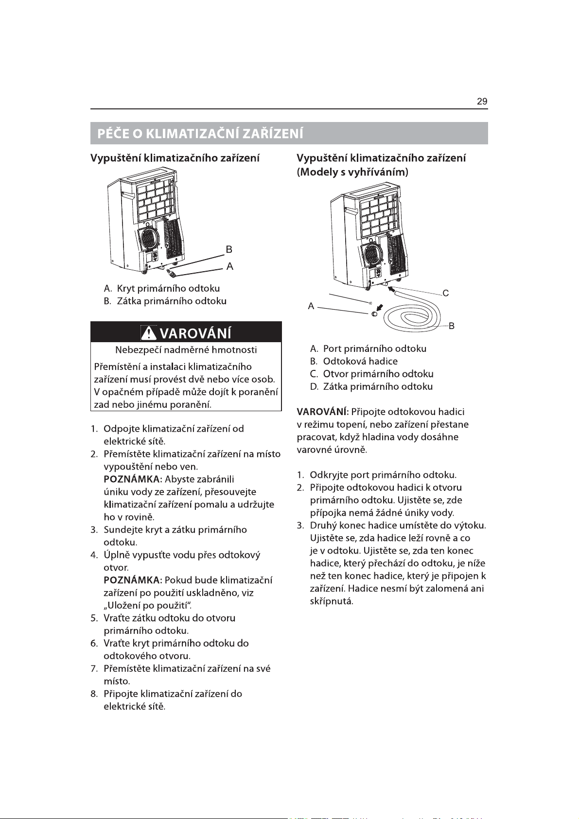
D
Page 90
Page 91
Page 92
Page 93
Page 94
Page 95
Page 96
Page 97
Page 98
Page 99
Page 100
 Loading...