

Hisense AMS-09UR4SNZA2, AMS-12UR4SNZA2, AMW2-20U4SKB, AMW3-24U4SKB, AMW4-28U4SKB Service Manual

MULTI-SPLIT TYPE AIR CONDITONER
SERVICE MANUAL
V: 2.0
●
INDOOR UNIT:
AMS-09UR4SNZA2
AMS-12UR4SNZA2
●INDOOR UNIT:
AMW2-20U4SKB
AMW3-24U4SKB
AMW4-28U4SKB
Hisense Corporation
Table of contents
Page
1.OPERATING RANGE 1
2.SPECIFICATION 2
2-1 Unit specifications 2
2-2 Major component specifications 4
2-3 Other component specifications 5
3.OUTLINES AND DIMENSIONS 6
3-1 INDOOR 6
3-2 OUTDOOR 7
4.REFRIGERANT FLOW DIAGRAM 9
4-1 Refrigerant flow diagram 9
4-2 Evacuation procedures 11
4-3 Evacuation direction 12
5.ELECTRICAL DATA 13
5-1 Electric wiring diagrams 13
5-2 Electric control 15
5-3 Sensor parameter 18
6.CONTROL MODE 20
6-1 Indoor control mode 16
6-2 Outdoor control mode 25
7.TROUBLESHOOTING 31
7-1 Error codes 31
8.CHECKING COMPONENTS 33
8-1 Check refrigerant system 33
8-2 Check parts unit 35
9.PARTS LIST 39
9-1 Indoor 39
9-2 Outdoor 44
11.. OOPPEERRAATTIINNGG RRAANNGGE
E
1
T emperature Indoor Air Intake Temp. Outdoor Air Intake Temp
Maximum
32℃ D.B./23℃ W.B. 43 ℃ D.B./26℃ W.B.
COOLING
Minimum
21℃ D.B./15℃ W.B. 21 ℃ D.B./15℃ W.B.
Maximum
27℃ D.B./18℃ W.B. 24℃ D.B./18℃ W.B.
HEATING
Minimum
20℃ D.B/≤15℃ W.B -7℃ D.B./-8℃ W.B.
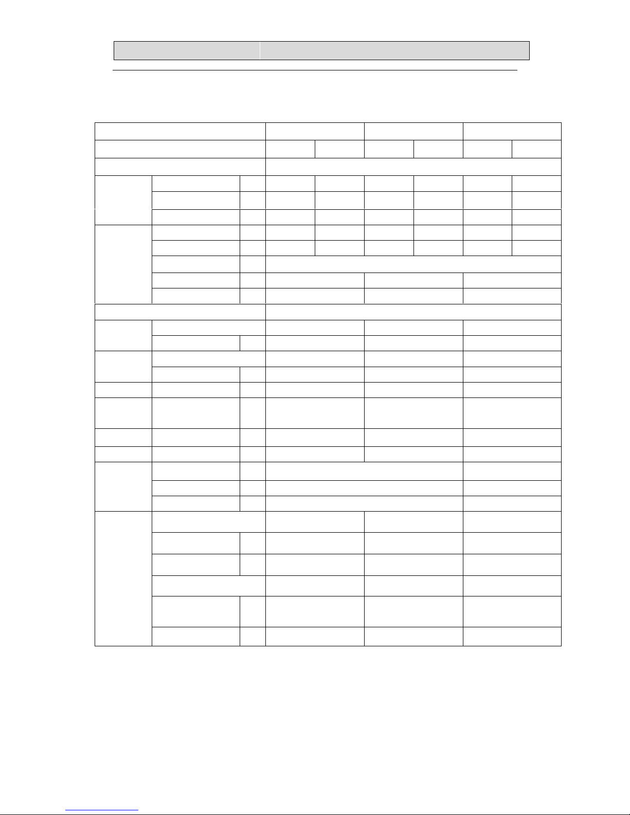
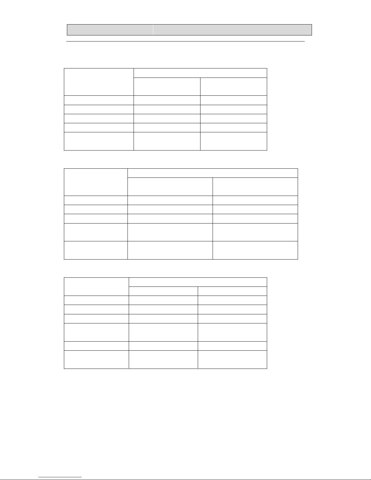
22.. SSPPEECCIIFFIICCAATTIIOONNSS
2
2-1. Unit specifications
2-1-1.OUTDOOR UNIT
NOTE :Test conditions:
Cooling : Indoor: DB27℃/ WB19℃ Outdoor: DB35℃/ WB24℃
Heating: Indoor: DB20℃/ WB15℃ Outdoor: DB7℃/ WB 6℃
Model AMW3-24U4SKB
AMW4-28U4SKB AMW2-20U4SNB
Function Cooling Heating Cooling Heating Cooling Heating
Power supply a.c 220V~230V/50Hz
Capacity kW 7.0 8.0 8.2 9.0 5.8 6.4
Dehumidification
l /h
---- ---- ---- ---- ---- ----
Capacity
Air flow m
3
/h ---- ---- ---- ---- ---- ---Rated current A 9.7 10.7 10.7 11.1 7.73 8.0
Rated input kW 2.18 2.22 2.4 2.5 1.7 1.75
Auxiliary heater A -----Power factor % 99.9% 99.9% 99.9%
Electrical
data
Max. current A 15.0 15.0 14.5
SEER/HSPF ----
Model JU1015D5 JU1015D5 SNB130FGYM
Compressor
Winding resistance (at25℃)
Ω 0.661/0.650/0.639 0.661/0.650/0.639 0.58(20℃)
Model YDK70-6H-3 YDK70-6H-3 YDK55-6I-8 Outdoor
fan motor
Winding resistance (at20℃)
Ω M:78;A:80 M:78;A:80 M:185;A:200
Net size L×W×H cm 75×19×25 103×34×84 98×35×64
Package
size
L×W×H cm 84×27×31 112×46×98 108×42×72
Net weight kg 8.0 67 45
Gross weight kg 9.5 72 51
Liquid pipe mm 6.35 6.35
Gas pipe mm 9.52 9.52
Refrigerant
piping
Connection method Flare Flare
Air direction ---- ---- ----
Sound level (Hi) dB 57 57 57
Fan speed (Hi) rpm 830 830 840
Fan speed regulator 3 3 3
Refrigerant filling
capacity(R410a)
kg 2.2 2.5 1.4
Special
remarks
Throttle mode
EEV EEV EEV
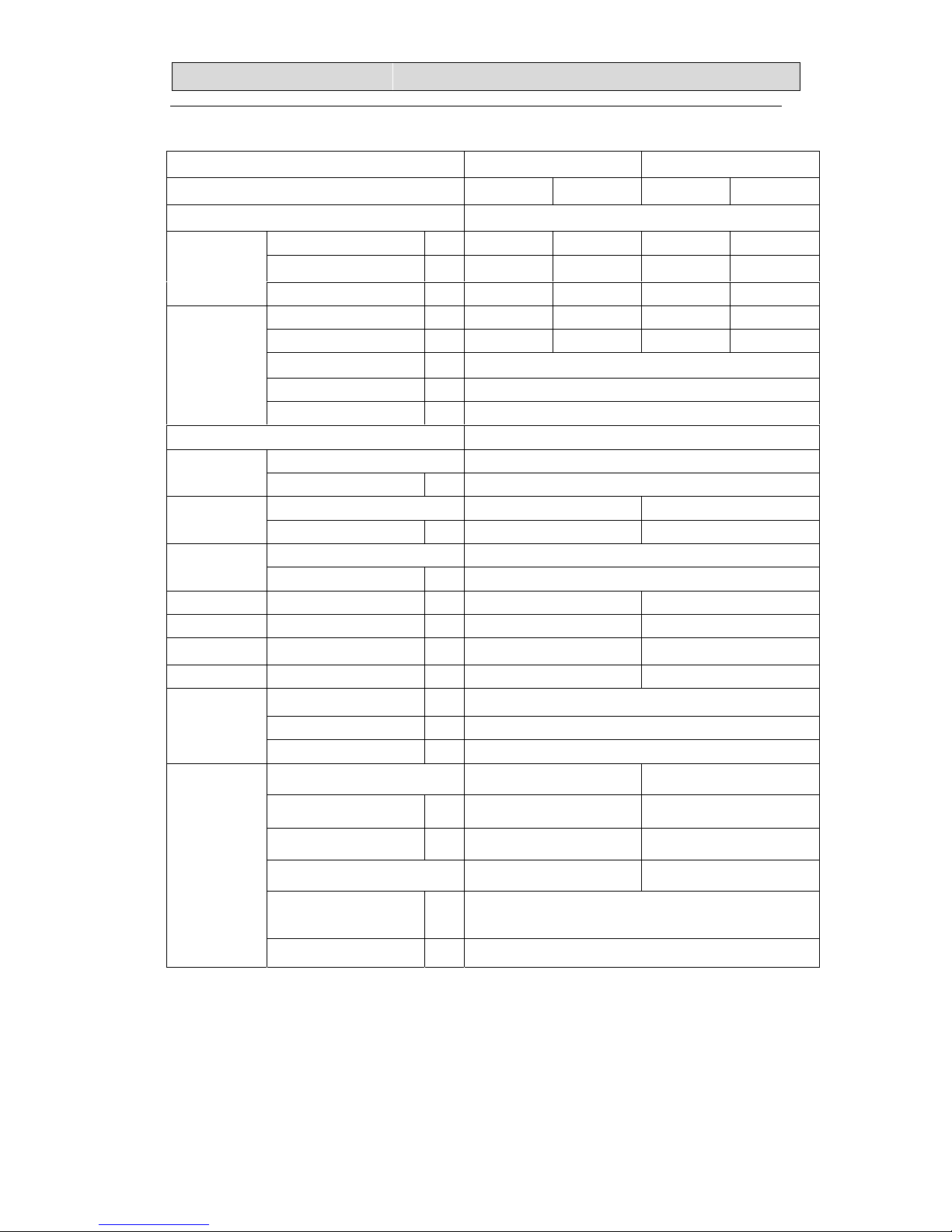
22.. SSPPEECCIIFFIICCAATTIIOONNSS
3
2-1-2.INDOOR UNIT
NOTE :Test conditions:
Cooling : Indoor: DB27℃/ WB19℃ Outdoor: DB35℃/ WB24℃
Heating: Indoor: DB20℃/ WB15℃ Outdoor: DB7℃/ WB 6℃
Model AMS-09UR4SNZA2 AMS-12UR4SNZA2
Function Cooling Heating Cooling Heating
Power supply a.c 220V~230V/50Hz
Capacity kW 2.6 3.0 3.2 3.8
Dehumidification l /h 1.1 1.1 1.4 ----
Capacity
Air flow m3/h 420 520 450 560
Running current A 0.18 0.18 0.18 0.18
Rated input kW 40 40 40 40
Auxiliary heater A ---Power factor % ----
Electrical data
Starting current A ----
SEER/HSPF ----
Model ----
Compressor
Winding resistance (at25℃)
Ω ----
Model YYW16-4-532 YYW16-4-532 Indoor
fan motor
Winding resistance (at20℃)
Ω M:364;A:400.5; M:364;A:400.5;
Model ---- Outdoor
fan motor
Winding resistance (at20℃)
Ω ----
Net size L×W×H cm
75×25×19
75×25×19
Package size L×W×H cm
84×31×27
84×31×27
Net weight kg 8.0 8.0
Gross weight kg 9.5 9.5
Liquid pipe mm 6.35
Gas pipe mm 9.52
Refrigerant
piping
Connection method ---Air direction 6 6
Sound level (Hi) dB 37 37
Fan speed (Hi) rpm 1200 1300
Fan speed regulator
Refrigerant filling
capacity(R410a)
kg ----
Special
remarks
Throttle mode ----

22.. SSPPEECCIIFFIICCAATTIIOONNSS
4
2-2. Major component specifications
2-2-1.INDOOR FAN MOTOR
PARAMETER
ELECTRIC
PERFORMANCE
AMS-09UR4SNZA2 AMS-12UR4SNZA2
Motor model YYW16-4-532 YYW16-4-532
Rated power source 220V 50Hz 220V 50Hz
Phases/Poles 1/4 1/4
Rated load output(W) 16 16
Rated speed(r/min) -- --
Ambient
temperature(℃)
-5℃~+43℃. -5℃~+43℃.
2-2-2 OUTDOOR FAN MOTOR
PARAMETER ELECTRIC
PERFORMANCE
AMW3-24U4SKB
AMW4-28U4SKB
AMW2-20U4SNB
Motor model YDK70-6H-3
YDK55-6I-8
Rated power source 220V 50Hz 220V 50Hz
Phases /Poles 1/6 1/6
Rated load output(W) 65 47
Ambient temperature(℃) -5℃~+43℃. -5℃~+43℃.
2-2-3. COMPRESSOR
PARAMETER ELECTRIC
PERFORMANCE
AMW3-24U4SKB
AMW4-28U4SKB
AMW2-20U4SNB
Compressor model JU1015D5 SNB130FGYM
Compressor type Rotary Rotary
Rated power 1585W 1190W
Current (A) 8.8 8.1
Motor type DC brushless motor DC brushless motor
Starting type DC Inverter DC Inverter
Motor
Winding resistance
0.661/0.650/0.639Ω(at 25℃)
U-V/V-W/W-U
0.58/0.58/0.58Ω(at 20℃)
U-V/V-W/W-U
Number of cylinder 2 2
Oil type HAF68D1 or HAF68D1U
or α8HES-H
FV50S
Oil charge (cc) 840 350
Ambient temperature(℃) -5℃~+43℃. 5℃~+43℃
22.. SSPPEECCIIFFIICCAATTIIOONNSS
5
2-3. Other component specifications
2-3-1. INDUCTANCE
PARAMETER
ELECTRIC
PERFORMANCE
AMW3-24U4SKB
AMW4-28U4SKB
AMW2-20U4SNB
Inductance model
RC800HS-3
R2050HSB
Rated power source 220V 50Hz 220V 50Hz
Rated current(A) 20 20
Rated inductance
800(μH)±20% 5.2(mH)±10%
Ambient
temperature(℃)
-30℃~+155℃. -30℃~+220℃.
2-3-2. FILTER
PARAMETER ELECTRIC
PERFORMANCE
AMW3-24U4SKB
AMW4-28U4SKB
AMW2-20U4SNB
Filter model RTNF250-25T068X-03LF RTNF250-25T068X-03LF
Rated current(A) 20 20
Rated power source AC 220V—50Hz AC 220V—50Hz
Filter frequency
range
150K—30MHHz 150K—30MHHz
Temperature
range(℃)
-25℃~+85℃. -25℃~+85℃.
2-3-4. STEPPER MOTOR
PARAMETER ELECTRIC
PERFORMANCE
AMS-09UR4SNZA2 AMS-12UR4SNZA2
Stepper Motor model 24BYJ48-CP 24BYJ48-CP
Voltage(DC) 12V 12V
Number of phase 4 4
Drive mode 1-2phase excitation
unipolar drive
1-2phase excitation
unipolar drive
Resistance per phase
300Ω±7% 300Ω±7%
Temperature
range(℃)
-10℃~+40℃. -10℃~+40℃.
2-3-5. OVERLOAD PROTECTION
NONE.

33.. OOUUTTLLIINNEESS AANNDD DDIIMMEENNSSIIOO
6
3-1. INDOOR(MODEL: AMS-09UR4SNZA2、AMS-12UR4SNZA2)
23mm631mm
94mm
190mm
250mm
750mm
50mm
50mm
50mm
65mm

33.. OOUUTTLLIINNEESS AANNDD DDIIMMEENNSSIIOO
7
3-2.OUTDOOR(MODEL: AMW2-20U4SNB)
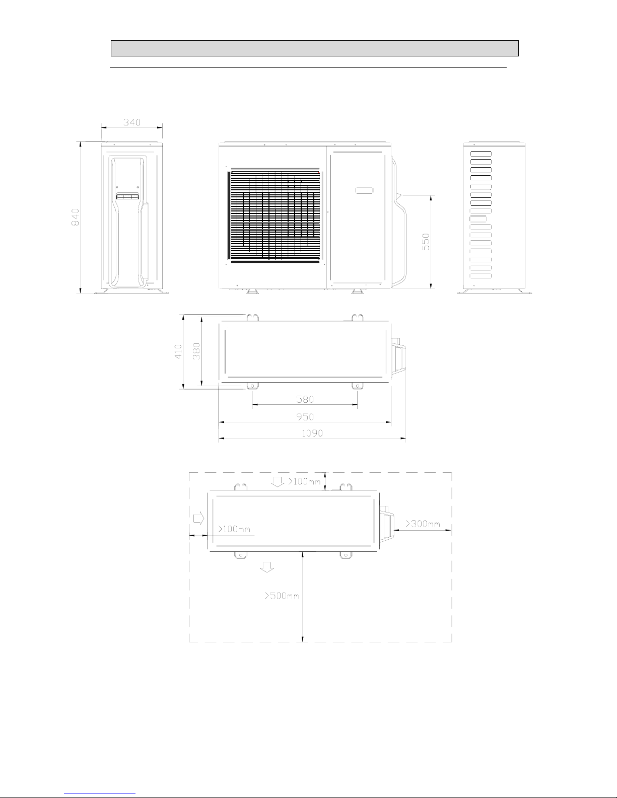
33.. OOUUTTLLIINNEESS AANNDD DDIIMMEENNSSIIOO
8
3-3.OUTDOOR(MODEL: AMW3-24U4SKB、AMW4-28U4SKB)

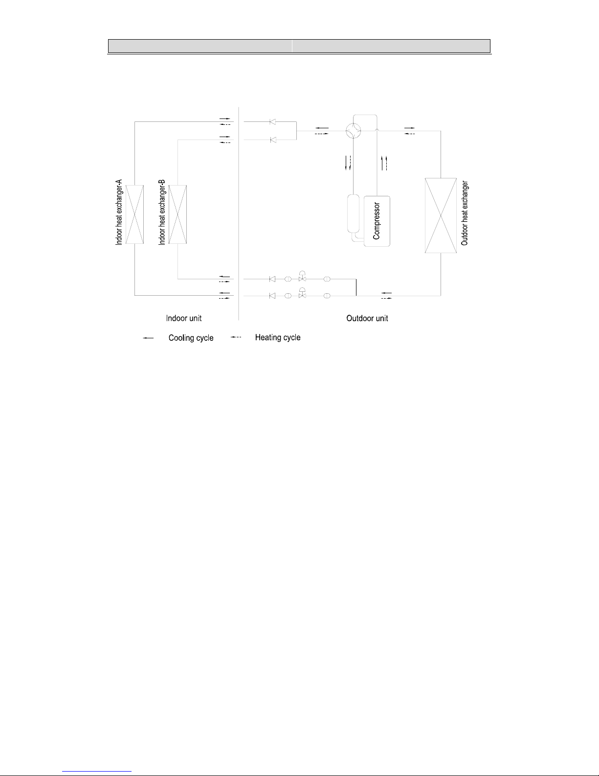
44.. RREEFFRRIIGGEERRAANNTT FFLLOOWW DDIIAAGGRRAAM
M
9
4-1. Refrigerant flow diagram :
MODEL:AMW3-24U4SKB、AMW4-28U4SKB
Filter
B机
A机
A机
C机
B机
D机
C机
D机
Remark: The part is only for AMW4-28U4SKB
COOLING CYCLE
HEATING CYCLE
44.. RREEFFRRIIGGEERRAANNTT FFLLOOWW DDIIAAGGRRAAM
M
10
MODEL:AMW2-20U4SNB
EEV B
EEV A
4-way valve
Filter
B
机
A机
A机
B机
Filter
44.. RREEFFRRIIGGEERRAANNTT FFLLOOWW DDIIAAGGRRAAM
M
11
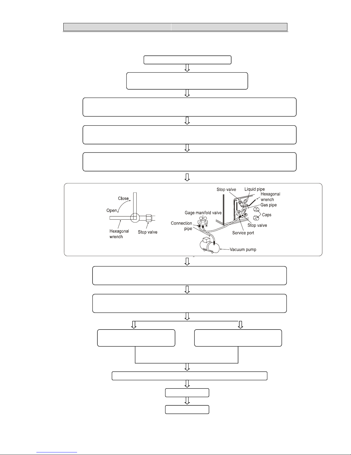
4-2. Evacuation procedures:
EVACUATION PROCEDURES
Connect the refrigerant pipes (both the liquid an
d
g
as pipes) between the indoor and the outdoor units.
Remove service port cap of the stop valve A and connect gage manifold valve and vacuum
p
ump to it.
Run the vacuum pump for more than 15 minutes and at this time confirm that the pressure
gage indicates -0.1Mpa(-76 cmHg).
Stop pump and keep the pressure for one or two minutes. Make sure the pressure is no
change(if the pressure is changed to high, there is some leakage for the pipe connection).
Remove gage manifold valve quickly from the service port of the stop valve A.
full open the stop valves A on gas and liquid pipe sides.
T ot al pi pe len gth is in the range :
N
o gas charge is needed
T ot al pipe length exceeding the limit:
Charge the prescribed amount of gas.
Tighten the cap to the service port to obtain the initial status.
Retighten the cap.
Leak test
Repeat the steps above for other valves(B\C\D), be sure all refrigerant pipes are
connected and evacuated, and all valves are full opend.

44.. RREEFFRRIIGGEERRAANNTT FFLLOOWW DDIIAAGGRRAAM
M
12
4-3. Evacuation direction:
MAX. Refrigerant pipe length and height difference:
Modle
AMW3-24U4SKB
AMW4-28U4SKB
AMW2-20U4SNB
Pipe length per. Indoor unit(a/b/c/d) 25m 20m
Total pipe length for multi-system (a+b+c+d) 60m 40m
Height difference (I.D ~ O.D) 15m 15m
Height difference (I.D ~ I.D) 7.5m 7.5m
*Do your best to reduce the pipe length. Long pipe may cause capacity of the indoor unit incline.
Total refrigerant pipe length
Outdoor unit precharged
0m~20m 20m~60m
AMW3-24U4SKB 2200g 0g
AMW4-28U4SKB 2500g 0g
Xg = 15g / m × (Total pipe length(m) - 20)
Total refrigerant pipe length
Outdoor unit precharged
0m~15m 15m~40m
AMW2-20U4SNB 1400g 0 Xg = 15g / m × (Total pipe length(m) - 15)

55.. EELLEECCTTRRIICCAALL DDAATTAA
13
5-1.Electrical wiring diagrams
INDOOR:AMS-09UR4SNZA2、AMS-12UR4SNZA2
OUTDOOR:
1)AMW4-28U4SKB
3( )
WHT
BLK
AUXILIARY HEATER
CN10
C
N
9
CN201
T-DISS
CN205
SUC-D
REDYEL
22211
12 1
EXPANSION VALVE D
ELECTRONIC
5
5
CN404 D-EV BLU
432
2341166
S
I
-
D
WHT
T02
1
1
YLW/GRN
4(SI)
2(N)
TERMINAL
1(L)
PANEL D
BLU
BRN
CONNECTION
CAPACITOR
1310785
BLU
RED
RED
4(SI)
2(N)
1(L)
4(SI)
2(N)
1(L)
2(N)
1(L)
FAN MOTOR
4-WAY VALVE
ELECTRIC WIRING DIAGRAM
COMPRESSOR
BLUWHT
V
W
449
9
8
8
7
7
6
6
5
5
IPM BOARD
-
BRN
BLU
BRIDGE
AC
AC
+
-
ELECTROLYTIC
+
BLU
BRN
C
N
4
CN1
PRESSUR
CN8 WHT
321
321
7
7
654
5648
899
10
10
RECTIFYING
VA
FILTER
CN7 FM WHT
1221
CN6 VA BLK
21
21
4
3
4
3
CN5
CN3
CN2
POWER FILTER BOARD
P2
+
P1
CAPACITOR
YLW
1
1
2
12
1
114423
23
8
8
65
5677 9910
10
BLU
2
BRN
2
L2
ORG
331
2
1
2
889
9
4
4
C
N
5
0
1
W
H
T
553
2
3
2
116
7
6
7
6
6
CN301 WHT
CN901 WHT
CN702 RED
INDUCTOR
L1
T1 T2 T3T1 T2T3T2 T3
6
6
123
123
456
4
65
54321
32154
654
56
4
T1
121
11222112233
CN202
YEL
CN203
BLU
GREEN
6
6
11432
234
12345
4321 5
CN402 B-EV WHT
WHT BLK
T05
BLK
RED
1
1
T
0
4
1
1
1
1
S
I
-
A
S
I
-
B
S
I
-
C
2
2
CN401 A-EV RED
11543
345
BLU
T
0
1
1
1
ORG
T03
6
6
CN204
T-DEF
CN207
PIP-D
CN206
T-PIP-A -B -C T-COIL T-SUC T-OUTT-SUC-A -B -C
CONTROL BOARD
CN403 C-EV BLK
5
5
YLW/GRN
N
-
U
RED
W
H
T
EXPANSION VALVE B
EXPANSION VALVE A
ELECTRONIC
ELECTRONIC ELECTRONIC
EXPANSION VALVE C
CM
FM
POWER
PANEL
TERMINAL
BLU
FUSEBRN
CONNECTION
BRN
BLU
PANEL C
1(L)
TERMINAL
YLW/GRN
2(N)
4(SI)
CONNECTION
YLW/GRN
PANEL B
TERMINAL
B
L
U
BRN
CONNECTION
PANEL A
TERMINAL
YLW/GRN
B
L
U
BRN
YLW/GRN
BRN
 Loading...