

Hisense AMS-07UR4SN4, AMS-07UR4SNUP4, AMS-07UR4SNVG4, AMS-07UR4SNVQ4, AMS-07UR4SNUL4 Service Manual
...Page 1

MULTI-SPLIT TYPE AIR CONDITONER
SERVICEMANUAL
V:7.1
●INDOOR UNIT:
AMS-07UR4SN(VG/VT/VL/VQ/UP/UL/UQ/NS/ZC/ZA/NT/NK/NM/VM)4
AMS-09UR4SN(VG/VT/VL/VQ/UP/UL/UQ/NS/ZC/ZA/NT/NK/NM/VM)4
AMS-12UR4SN(VG/VT/VL/VQ/UP/UL/UQ/NS/ZC/ZA/NT/NK/NM/VM)4
AMS-07/09/12UR4SG(NK/NM/VT/VQ)4
AMS-09/12UR4SPSC4
AMS-18U4SV(VG/VQ/VL/VT/UP/UL/UQ/NT/NK/NM
)
4
AMD-09UX4SJD
AMD-12UX4SJD
AMD-18UX4SJD
AMC-12UX4SAA
AMC-18UX4SAA
●OUTDOOR UNIT:
Hisense Corporation
AMW2-16U4SGC1
AMW2-16U4SGD1
AMW2-20U4SNC1
AMW2-20U4SZD1
AMW3-20U4SZD1
AMW3-24U4SAD1
AMW4-28U4SAD1
-
AMW3-20U4SZD
AMW3-24U4SZD
AMW3-24U4SKC
AMW4-28U4SKC
AMW4-36U4SAC
AMV-12UR4SA
AMV-18UR4SA
AS-09/12UR4SVETD5(TG5/TC5/TE5/TF5)
AS-18UR4SFATD5(TD5/T G5/TC5)
Page 2

Table of Contents
Page
1.OPERATING RANGE 1
2.SPECIFICATION 2
2-1 Unit specifications 2
2-2 Major component specifications 12
2-3 Other component specifications 15
3.OUTLINES AND DIMENSIONS 17
3-1 INDOOR 17
3-2 OUTDOOR 23
4.REFRIGERANT FLOW DIAGRAM 28
4-1 Refrigerant flow diagram 28
4-2 Evacuation procedures 31
4-3 Evacuation direction 32
4-4 Air flow and ESP Chart(Duct type) 34
5.ELECTRICAL DATA 36
5-1 Electric wiring diagrams 36
5-2 Electric control 55
5-3 Digital Display Switch of Outdoor 63
5-3 Sensor parameter 66
6.CONTROL MODE 74
6-1 Indoor control mode 74
6-2 Outdoor control mode 77
7.TROUBLESHOOTING 80
7-1 Error codes 80
8.CHECKING COMPONENTS 92
8-1 Check refrigerant system 92
8-2 Check parts unit 94
9. APPENDIX(AS Series Wall Mounted Type) 101
Page 3

11.. OOPPEERRAATTIINNGG RRAANNGGE
E
1
T emperature Indoor Air Intake Temp. Outdoor Air Intake Temp
COOLING
Maximum
32℃ D.B./23℃ W.B. 43 ℃ D.B./26℃ W.B.
Minimum
21℃ D.B./15℃ W.B. 21 ℃ D.B./15℃ W.B.
HEATING
Maximum
27℃ D.B./18℃ W.B. 24℃ D.B./18℃ W.B.
Minimum
20℃ D.B/≤15℃ W.B -10℃ D.B./-11℃ W.B.
Page 4
22.. SSPPEECCIIFFIICCAATTIIOONNSS
2
2-1. Unit specifications
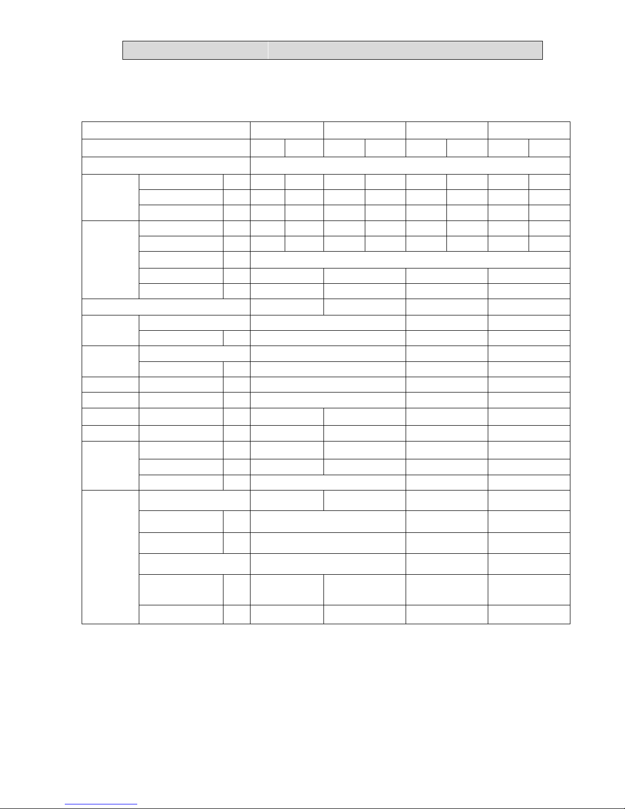
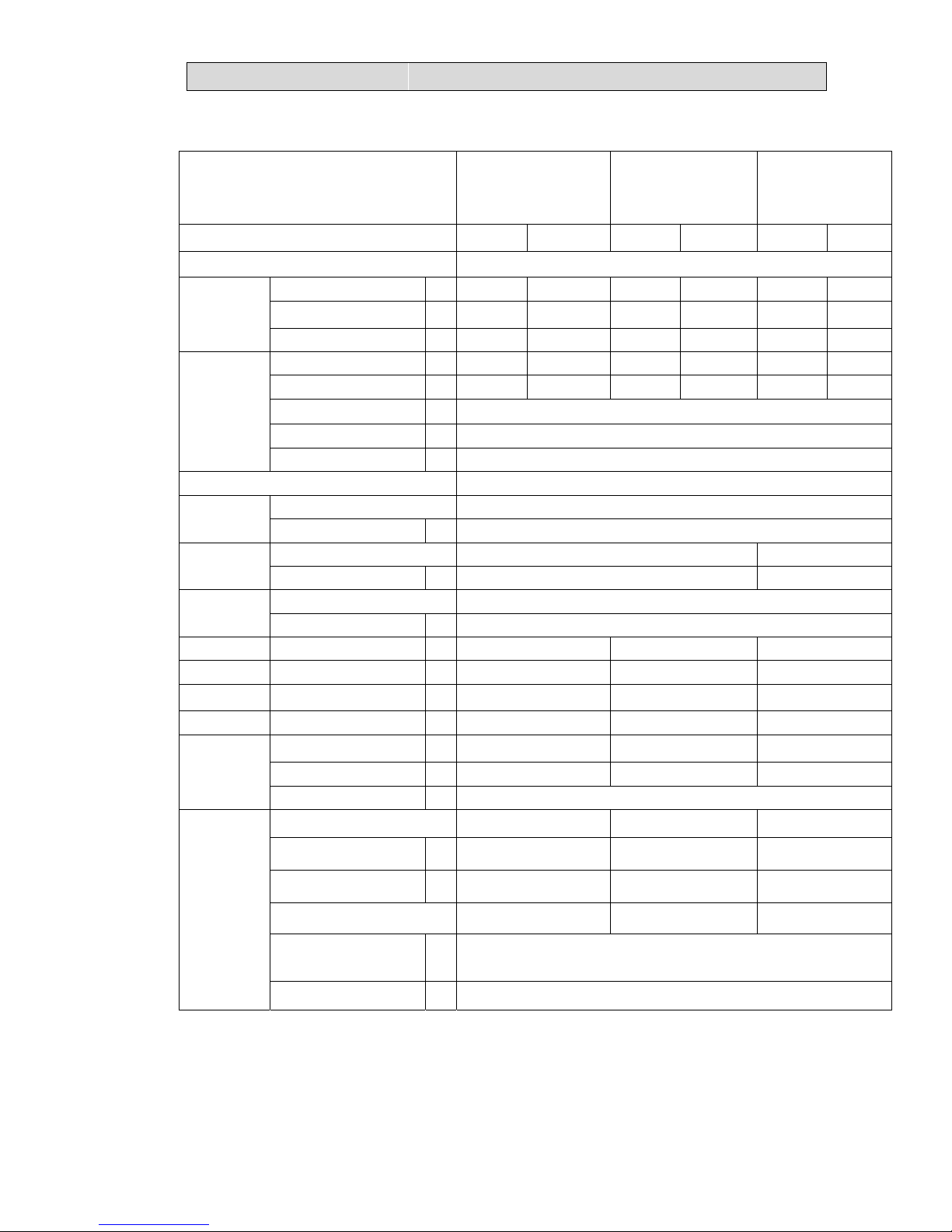
2-1-1.OUTDOOR UNIT
Model AMW4-28U4SKC AMW3-24U4SKC AMW2-20U4SNC1 AMW2-16U4SGC1
Function Cooling Heating Cooling Heating Cooling Heating Cooling Heating
Power supply AC 220V~240V/50Hz
Capacity
Capacity kW 8.2 9.0 7.0 8.0 5.8 6.4 4.6 5.3
Dehumidification l /h ---- ---- ---- ---- ---- ---- ---- ----
Air flow m3/h ---- ---- ---- ---- ---- ---- ---- ----
Electrical data
Rated current A 10.7 11.1 9.7 10.1 7.7 8.0 6.1 5.7
Rated input kW 2.4 2.49 2.18 2.21 1.7 1.75 1.4 1.3
Auxiliary heater A ------
Power factor % 99.9% 99.9% 99.9% 99.9%
Max. current A 15.0 15.0 14.5 10.0
EER/CPOP 3.42/.362 3.21/3.62 3.41/3.66 3.29/4.08
Compressor
Model
ATL165SD-C9AU
DA130S1C-20FZ DA130S1C-20FZ
Winding resistance
Ω 0.590
(at75℃)
0.95(20℃) 0.95(20℃)
Outdoor
fan motor
Model YDK70-6H-3 YDK55-6I-8 YDK29-6I-22
Winding resistance (at20℃)
Ω M:78;A:80 M:185;A:200 M:283.5;A:180
Net size L×W×H cm 109×41×84 98×35×64
80×26×57
Package size L×W×H cm 112×46×98 108×42×72
94×36×64
Net weight kg 67 66 46.5 36.5
Gross weight kg 77 76 52.5 40
Refrigerant
piping
Liquid pipe mm 6.35×4 6.35×3 6.35×2 6.35×2
Gas pipe mm 9.52×4 9.52×3 9.52×2 9.52×2
Connection method Flare Flare Flare
Special
remarks
Air direction ---- ---- ---- ----
Sound level (Hi) dB 57 57 56
Fan speed (Hi) rpm 840 840 900
Fan speed regulator 3 3 3
Refrigerant filling
capacity(R410a)
kg 2.4 2.1 1.4 1.27
Throttle mode EEV EEV EEV EEV
Page 5
22.. SSPPEECCIIFFIICCAATTIIOONNSS
3
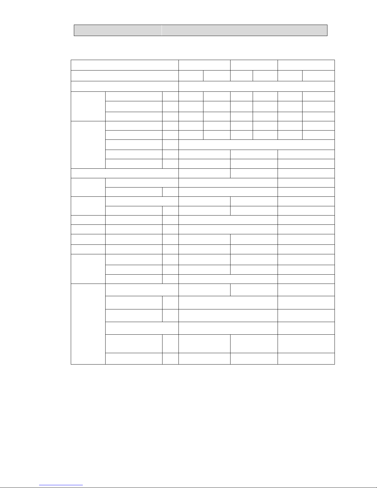
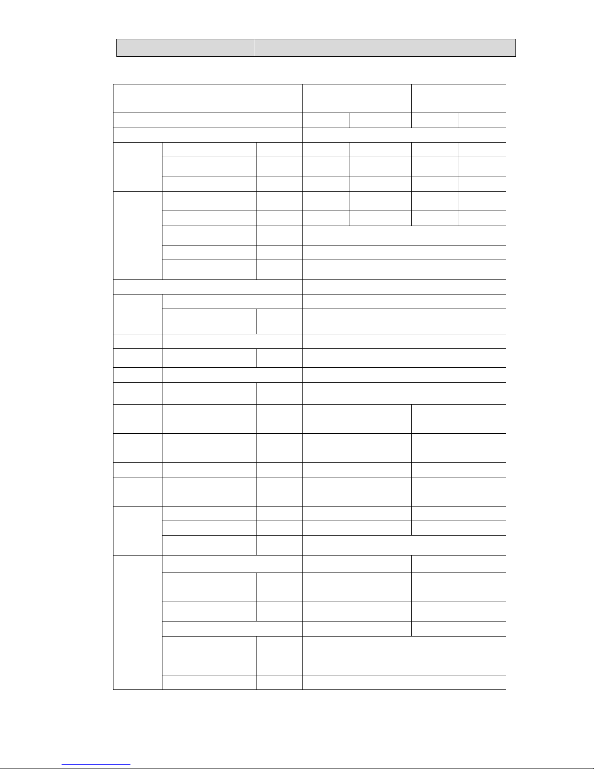
Model AMW3-20U4SZD AMW3-24U4SZD AMW4-36U4SAC
Function Cooling Heating Cooling Heating Cooling Heating
Power supply AC 220V~240V/50Hz
Capacity
Capacity kW 6.0 7.0 7 7.8 10 1.1
Dehumidification l /h ---- ---- ---- ---- ---- ----
Air flow m3/h ---- ---- ---- ---- ---- ----
Electrical data
Rated current A
8.55
8.58 10.0 9.5 14.5 14.0
Rated input kW 1.87 1.9 2.18 2.1 3.1 3.04
Auxiliary heater A ------
Power factor % 99.9% 99.9% 99.9%
Max. current A 13.5 15.5 22.0
EER/COP 3.21/3.70 3.21/3.71 3.22/3.62
Compressor
Model ATL165SD-C9AU ATL232SJNC9AU
Winding resistance
Ω 0.590
(at75℃)
0.95(20℃)
Outdoor
fan motor
Model YDK55-6I-8 YDK70-6H-3 YDK95-6-9043
Winding resistance (at20℃)
Ω M:185;A:200 M:78;A:80 M:59.1;A:85.8
Net size L×W×H cm 98×35×64 109×41×84
Package size L×W×H cm 108×42×72 111×46×98
Net weight kg 52 53 67
Gross weight kg 56 57 77
Refrigerant
piping
Liquid pipe mm 6.35×3 6.35×3 6.35×4
Gas pipe mm 9.52×3 9.52×3 9.52×4
Connection method Flare Flare
Special
remarks
Air direction ---- ---- ----
Sound level (Hi) dB 57 60
Fan speed (Hi) rpm 840 800
Fan speed regulator 3 3
Refrigerant filling
capacity(R410a)
kg 1.6 1.75 2.6
Throttle mode EEV EEV EEV
Page 6
22.. SSPPEECCIIFFIICCAATTIIOONNSS
4
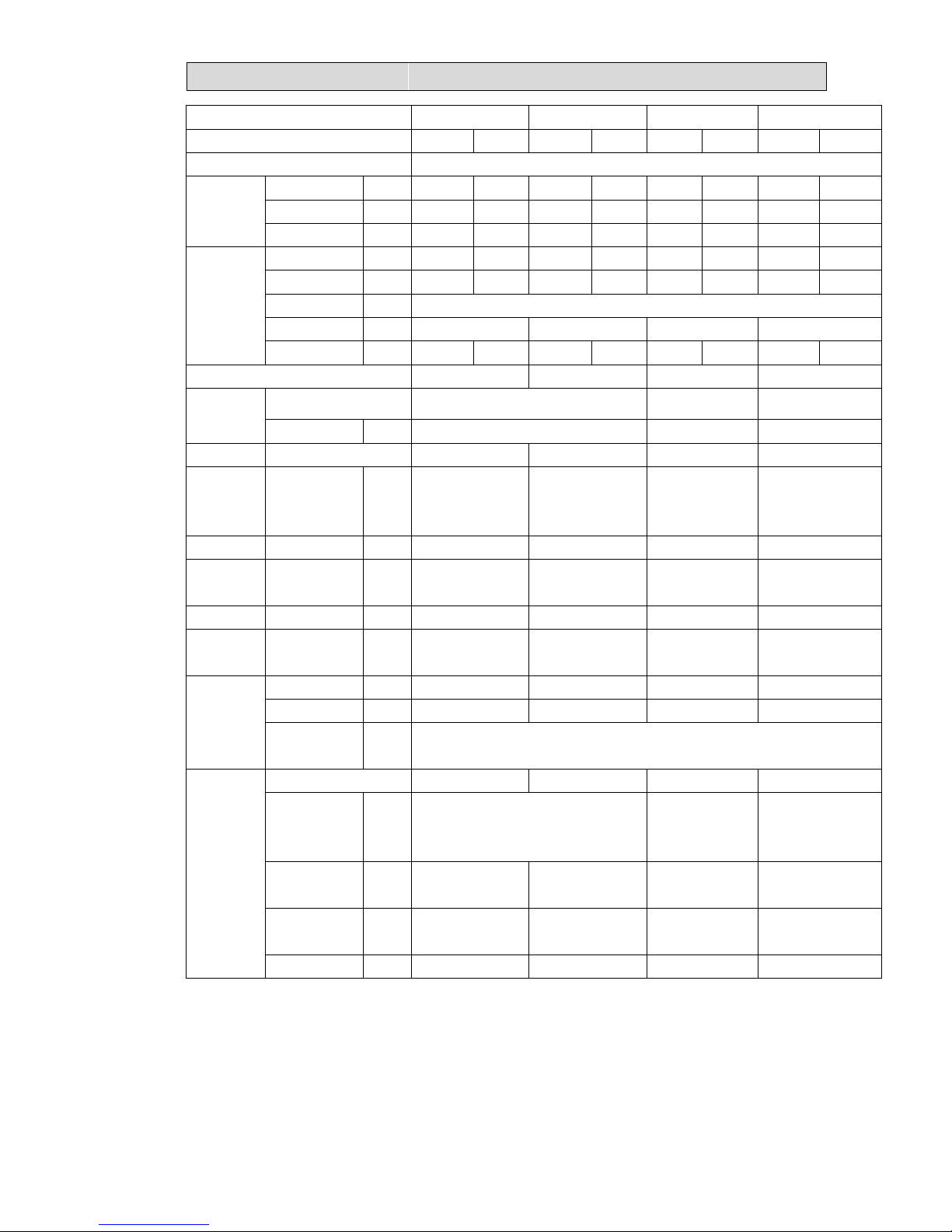
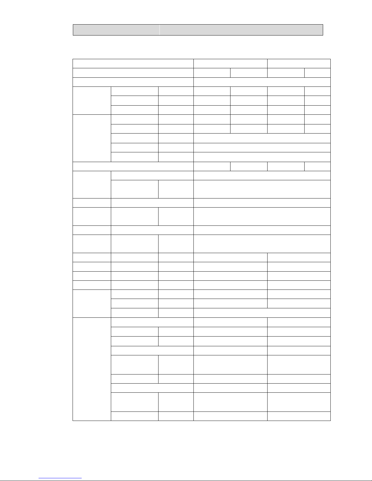
Model AMW2-16U4SGD1 AMW2-20U4SZD1 AMW3-20U4SZD1 AMW3-24U4SAD1
Function Cooling Heating Cooling Heating Cooling Heating Cooling Heating
Power supply a.c 220V~240V/50Hz
Capacity
Capacity kW 4.6 5.3 5.8 6.4 6 2 7 8.4
Dehumidification l /h ---- ---- ---- ---- ---- ---- ---- ----
Air flow m3/h ---- ---- ---- ---- ---- ---- ---- ----
Electrical
data
Rated current A 6.1 5.7 7.7 8 8 8 8 9.4
Rated input kW 1.4 2.1 1.7 1.75 1.8 1.9 1.8 2.2
Auxiliary heater A ------
Power factor % 99.90% 99.90% 99.90% 99.90%
Max. current A 10 9.6 12 13 13.5 13.5 12.5 14
SEER/SCOP 5.7/3.8 5.7/3.8 6.8/3.9 7.1/3.82
Compressor
Model DA130S1C-20FZ1 ATL165SD-C9AU DA200S2C-10MT
Coil resistance Ω 0.95 (20℃) 0.59(75℃) 0.53(20℃)
Outdoor Model ZWA138D08A ARW4401QH ARW4401QH SIC-71FW-D8121-1
fan motor
Winding
resistance
(at20℃)
Ω / / / /
Net size L×W×H cm 80×26×57 98×35×64 98×35×64 95×34×84
Package
size
L×W×H cm 95×37×65 105×40×70 105×40×70 111×46×98
Net weight kg 36.5 46.5 53 66
Gross
weight
kg 40 52.5 57 76
Refrigerant
piping
Liquid pipe mm 6.35×2 6.35×2 6.35×3 6.35×3
Gas pipe mm 9.52×2 9.52×2 9.52×3 9.52×3
Connection
method
Flare
Special
remarks
Air direction ---- ---- ---- ----
Sound level
(Low/Hi/Sound
power)
dB 53/56/64 --/57/68 53/59/68
Fan speed
(Low/Med/Hi)
rpm 500/750/900 620/740/840 620/740/840 500/640/780
Refrigerant filling
capacity(R410a)
kg 1.27 1.4 1.75 2.2
Throttle mode EEV EEV EEV EEV
Page 7
22.. SSPPEECCIIFFIICCAATTIIOONNSS
5
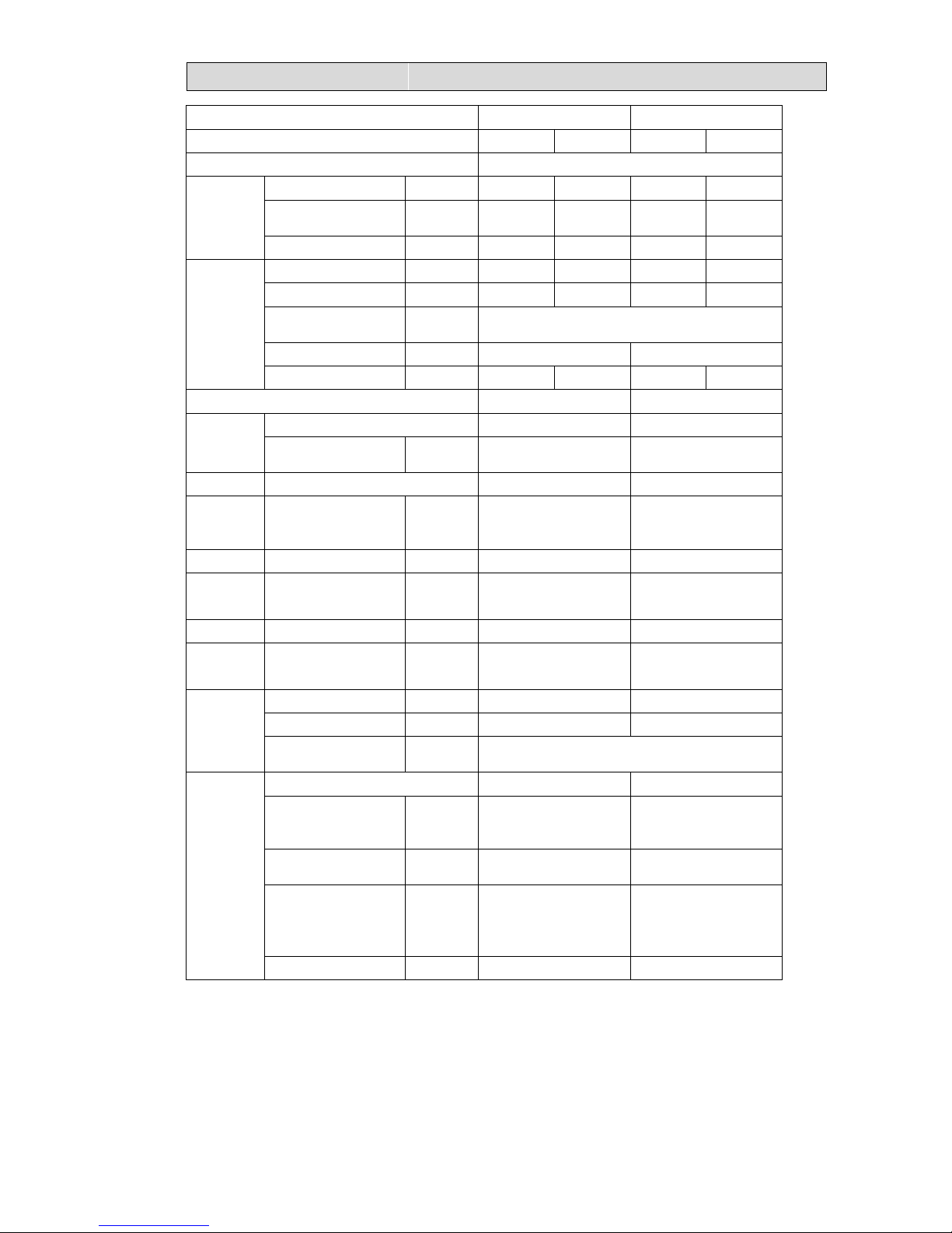
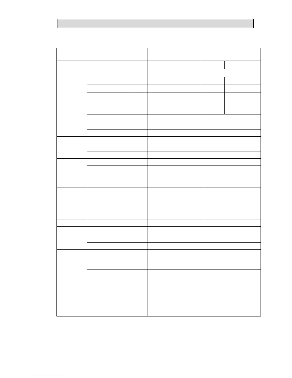
Model AMW4-28U4SAD1 AMW4-36U4SAD1
Function Cooling Heating Cooling Heating
Power supply a.c 220V~240V/50Hz
Capacity
Capacity kW 8.2 9 10 11
Dehumidification l /h ---- ---- ---- ----
Air flow m3/h ---- ---- ---- ----
Electrical
data
Rated current A 9.6 9.6 13.2 12.4
Rated input kW 2.2 2.2 2.98 2.8
Auxiliary heater A __
Power factor % 99.90% 99.90%
Max. current A 14 15 20.5 20.5
SEER/SCOP 7.2/3.81 7.2/3.81
Compressor
Model DA230S2C-31MT DA250S2C-30MT
Coil resistance Ω 0.73(20℃) 0.55(20℃)
Outdoor Model SIC-71FW-D8121-1 SIC-71FW-D8121-1
fan motor
Winding resistance
(at20℃)
Ω / /
Net size L×W×H cm 95×34×84 95×34×84
Package
size
L×W×H cm 111×46×98 111×46×98
Net weight kg 66 66
Gross
weight
kg 77 77
Refrigerant
piping
Liquid pipe mm 6.35×4 6.35×4
Gas pipe mm 9.52×4 9.52×4
Connection method Flare
Special
remarks
Air direction ---- ----
Sound level
(Low/Hi/Sound power)
dB 53/59/68 --/59/68
Fan speed (Low/Med/Hi) rpm 500/640/780 540/700/800
Refrigerant filling
capacity(R410a)
kg 2.6 2.6
Throttle mode EEV EEV
NOTE :Test conditions:
Cooling : Indoor: DB27℃/ WB 19℃ Outdoor: DB35℃/ WB24℃
Heating: Indoor: DB20℃/ WB15℃ Outdoor: DB7℃/ WB 6℃
Page 8
22.. SSPPEECCIIFFIICCAATTIIOONNSS
6
2-1-2.INDOOR UNIT
Model
AMS-07/09UR4SN
(VG/VT/VL/VQ/UP/UL/UQ/
NS/ZC/ZA/NT/NK/NM/VM)4
AMS-12UR4SN
(VG/VT/VL/VQ/UP/UL/U
Q/NS/ZC/ZA/NT/NK/NM/V
M)4
AMS-18UR4SV(VG4/VL
4/VT4/UP4/UL4/UQ4/V
Q4/NT4/NK4/NM4)
Function Cooling Heating Cooling Heating Cooling Heating
Power supply AC 220V~240V/50Hz
Capacity
Capacity kW 2.1/2.6 2.5/3.0 3.2 3.7 5.0 5.5
Dehumidification l /h 0.8 ---- 0.8 ---- 1.5 ----
Air flow
m3/h
400 520 450 560 800 900
Electrical data
Running current A 0.2 0.2 0.2 0.4 0.4 0.4
Rated input kW 0.04 0.04 0.04 0.04 0.085 0.085
Auxiliary heater A ----
Power factor % ----
Starting current A ----
EER/COP ----
Compressor
Model ----
Winding resistance (at25℃) Ω ----
Indoor
fan motor
Model YYW16-4-532 RPG25A-6
Winding resistance (at20℃) Ω M:364;A:400.5; M:211.2;A:211;
Outdoor
fan motor
Model ----
Winding resistance (at20℃)
Ω ----
Net size L×W×H cm 75×19×25(VQ:81×19×27) 75×19×25(VQ:81×19×27) 92×31.3×20.3
Package size L×W×H cm 80×31×25(VQ:88×33×26)80×31×25(VQ:88×33×26) 100.7×38×29.7
Net weight kg 7.5 7.5 12.0
Gross weight kg 9.0 9.0 14.0
Refrigerant pipin
g
Liquid pipe mm 6.35 6.35 6.35
Gas pipe mm 9.52 9.52 9.52
Connection method ----
Special
remarks
Air direction 6 6 6
Sound level (Hi) dB 39 40 49
Fan speed (Hi) rp
m
1150 1250 1300
Fan speed regulator 3 3 3
Refrigerant filling
capacity(R410a)
kg ----
Throttle mode ----
Page 9
22.. SSPPEECCIIFFIICCAATTIIOONNSS
7
Model
AMS-07/09UR4SG
(NK/NM/VT/VQ)4
AMS-12UR4SG
(NK/NM/VT/VQ)4
Function Cooling Heating Cooling Heating
Power supply AC 220V~240V/50Hz
Capacity
Capacity kW 2.1/2.6 2.5/3 3.5 4
Dehumidification l /h 0.8 ---- 0.8 ----
Air flow m3/h 550 550 600 600
Electrical
data
Running current A 0.1 0.1 0.12 0.12
Rated input kW 0.015 0.015 0.02 0.02
Auxiliary heater A ----
Power factor % ----
Starting current A ----
EER/COP ----
Compressor
Model ----
Winding resistance (at25℃) Ω ----
Indoor Model ARW7102QH
fan motor Winding resistance (at20℃) Ω /
Outdoor Model ----
fan motor Winding resistance (at20℃) Ω ----
Net size L×W×H cm 81.8×20.7×27
81.8×20.7×27(VQ:
86.8×21.8×27)
Package
size
L×W×H cm 91×28.5×38
91×28.5×38(VQ:
93×28.5×38)
Net weight kg 8.5 8.5
Gross
weight
kg 10 10
Refrigerant
piping
Liquid pipe mm 6.35 6.35
Gas pipe mm 9.52 9.52
Connection method ----
Special
remarks
Air direction 6 6
Sound level (Low/HiSound
Power )
dB 22/39/53 40
Fan speed (Low/Med/Hi) rpm 850/1000/1150 900/1050/1200
Fan speed regulator 3 3
Refrigerant filling
capacity(R410a)
kg ----
Throttle mode ----
Page 10
22.. SSPPEECCIIFFIICCAATTIIOONNSS
8
Model AMS-09UR4SPSC4 AMS-12UR4SPSC4
Function Cooling Heating Cooling Heating
Power supply a.c 220V~240V/50Hz
Capacity
Capacity kW 2.6 3.1 3.5 4.1
Dehumidification l /h 0.8 ---- 1.4 ----
Air flow m3/h 540 540 580 580
Electrical data
Running current A 0.13 0.13 0.15 0.15
Rated input kW 0.03 0.03 0.035 0.035
Auxiliary heater A ----
Power factor % ----
Starting current A ----
EER/COP ----
Compressor
Model ----
Winding resistance
(at25℃)
Ω ----
Indoor Model YYW13-4-5038
fan motor
Winding resistance
(at20℃)
Ω M:384.6;A:353.6
Outdoor Model ----
fan motor
Winding resistance
(at20℃)
Ω ----
Net size L×W×H cm
101.5×32×15.8 101.5×32×15.8
Package size L×W×H cm
111×41×26 111×41×26
Net weight kg 11.5 11.5
Gross weight kg 14 14
Refrigerant
piping
Liquid pipe mm 6.35 6.35
Gas pipe mm 9.52 9.52
Connection method ——
Special remarks
Air direction ---- ----
Sound level (Hi) dB 37 39
Fan speed (Hi) rpm
1100 1200
Fan speed regulator 4 4
Refrigerant filling
capacity(R410a)
kg ---- ----
Throttle mode ---- ----
Fan speed regulator 4 4
Refrigerant filling
capacity(R410a)
kg ---- ----
Throttle mode ---- ----
Page 11
22.. SSPPEECCIIFFIICCAATTIIOONNSS
9
Model AMC-12UX4SAA
AMC-18UX4SAA
Function Cooling Heating Cooling Heating
Power supply 220V~240V/50Hz
Capacity
Capacity kW 3.5 4 5 5.5
Dehumidification l /h 2.0 ---- 2.0 ----
Air flow m3/h 750 800 750 800
Electrical data
Running current A 0.32 0.32 0.32 0.32
Rated input kW 70 70 70 70
Auxiliary heater A ---- ----
Power factor % ---- ----
Starting current A ---- ----
SEER/HSPF ---- ----
Compressor
Model ---- ----
Winding resistance (at25℃) Ω ---- ----
Indoor
fan motor
Model YDK95-28-4-B
Winding resistance (at20℃) Ω M:240;A:245
Outdoor
fan motor
Model -----
Winding resistance (at20℃) 9.52 ----
Net size L×W×H cm
57x57x27(panel 65x65x3)
57x57x27(panel 65x65x3)
Package size L×W×H cm
77X75X31(panel 73X73X13) 77X75X31(panel 73X73X13)
Net weight kg 21 21
Gross weight kg 25.5 25.5
Refrigerant piping
Liquid pipe mm 6.35 6.35
Gas pipe mm 9.52 12.7
Connection method ----
Special remarks
Air direction ----
Sound level (Hi) dB 47 47
Fan speed (Hi) rpm 980 980
Fan speed regulator 3 3
Refrigerant filling
capacity(R410a)
kg ----
Throttle mode ----
Page 12
22.. SSPPEECCIIFFIICCAATTIIOONNSS
10
Model AMD-09UX4SJD
AMD-12UX4SJD AMD-18UX4SJD
Function Cooling Heating Cooling Heating Cooling Heating
Power supply a.c 220V~240V/50Hz
Capacity
Capacity kW 2.6 3.0 3.2 3.7 5.0 5.5
Dehumidification l /h 1.5 ---- 1.5 ---- 1.9 ----
Air flow m3/h 440 520 440 520 600 700
Electrical data
Running current A 0.2 0.2 0.2 0.2 0.3 0.3
Rated input kW 0.044 0.044 0.044 0.044 0.066 0.066
Auxiliary heater A ----
Power factor % ----
Starting current A ----
EER/COP ----
Compressor
Model ----
Winding resistance (at25℃) Ω ----
Indoor
fan motor
Model YSK95-25-4HS10 YSK95-40-4HS11
Winding resistance (at20℃) Ω M:329;A:225 M:138;A:178
Outdoor
fan motor
Model ----
Winding resistance (at20℃) Ω ----
Net size L×W×H cm 770×600×190 770×600×190 770×600×190
Package size L×W×H cm 946×692×236 946×692×236 946×692×236
Net weight kg 20 20 21
Gross weight kg 24 24 25
Refrigerant piping
Liquid pipe mm 6.35 6.35 6.35
Gas pipe mm 9.52 9.52 12.7
Connection method
Special remarks
Air direction ---- ---- ----
Sound level (Hi) dB 35 35 39
Fan speed (Hi) rpm 10pa:980,30pa:1150 10pa:980,30pa:1150 10pa:1290,30pa:1400
Fan speed regulator 6 6 6
Refrigerant filling
capacity(R410a)
kg ----
Throttle mode ----
Page 13
22.. SSPPEECCIIFFIICCAATTIIOONNSS
11
Model AMV-12UR4SA AMV-18UR4SA
Function Cooling Heating Cooling Heating
Power supply a.c 220V~240V/50Hz
Capacity
Capacity kW 3.5 4 5.2 5.5
Dehumidification l /h 1.2 ---- 1.8 ----
Air flow m3/h 800 800 800 800
Electrical
data
Running current A 0.38 0.38 0.38 0.38
Rated input kW 0.55 0.55 0.55 0.55
Auxiliary heater A ----
Power factor % ----
Starting current A ----
EER/COP ----
Compressor
Model ----
Winding resistance (at25℃) Ω ----
Indoor Model YSK110-22-4-A(HS24)
Outdoor Model ----
fan motor Winding resistance (at20℃) Ω ----
Net size L×W×H cm 99×68×23 99×68×23
Package
size
L×W×H cm 110×82×35 110×82×35
Net weight kg 27 27
Gross
weight
kg 33 33
Refrigerant
piping
Liquid pipe mm 6.35 6.35
Gas pipe mm 9.52 9.52
Connection method
Air direction ---- ----
Sound level (LOW/Hi/SOUND
POWER)
dB _/41/53 _/41/53
Special
remarks
Fan speed (Hi) rpm 620/740/840 630/720/850
Fan speed regulator 3 3
Refrigerant filling
capacity(R410a)
kg ----
Throttle mode ----
NOTE :Test conditions:
Cooling : Indoor: DB27℃/ WB19℃ Outdoor: DB35℃/ WB24℃
Heating: Indoor: DB20℃/ WB15℃ Outdoor: DB7℃/ WB 6℃
Page 14
22.. SSPPEECCIIFFIICCAATTIIOONNSS
12
2-2. Major component specifications
2-2-1.INDOOR FAN MOTOR
ELECTRIC
PERFORMANCE
PARAMETER
AMS-07/09/12UR4SN
(VG/VT/VL/VQ/UP/UL/UQ/NS/Z
C/ZA/NT/NK/NM/VM)4
AMS-07/09/12UR4SG
(NK/NM/VT/VQ)4
AMS-18UR4SV(VG4/
VL4/VT4/UP4/UL4/UQ
4/VQ4/NT4/NK4/NM4)
AMS-09(12)UR4SPSC4
Motor model
YYW16-4-532 ARW7102QH
RPG25A-6 YYW13-4-5038
Rated power
source
220V 50Hz 220V 50Hz 220V 50HZ 220V 50Hz
Phases/Poles 1/4 1/4 1/4 1/4
Rated load
output(W)
18 22 25 40
Rated
speed(r/min)
1250 1270 1300
Ambient
temperature(℃)
-5℃~+43℃. -20℃~+60℃. -5℃~+43℃. -5℃~+43℃.
ELECTRIC PERFORMANCE
PAR AMETE R
AMD-09UX4SJD AMD-12UX4SJD AMD-18UX4SJD
Motor model YSK95-25-4HS10 YSK95-40-4HS11
Rated power source 220V 50Hz 220V 50Hz
Phases/Poles 1/4 1/4
Rated load output(W) 25 42
Rated speed(r/min)
980/850/700(White)
1150/1070/980(Red)
1360/1300/1240(Red)
1240/1155/1050 (White)
Ambient temperature(℃) -5℃~+43℃. -5℃~+43℃
ELECTRIC PERFORMANCE
PAR AMETE R
AMC-12UX4SAA AMD-18UX4SAA
Motor model
YDK95-28-4-B
Rated power source 220V 50Hz
Phases/Poles 1/4
Rated load output(W) 25
Rated speed(r/min) 720/840/980
Ambient temperature(℃) -5℃~+43℃.
Page 15
22.. SSPPEECCIIFFIICCAATTIIOONNSS
13
ELECTRIC PERFORMANCE
PAR AMETE R
AMV-12UR4SA AMV-18UR4SA
Motor model YSK110-22-4-A(HS24)
Rated power source 220V 50Hz
Phases/Poles 1/4
Rated load output(W) 23
Rated speed(r/min) 630/720/850
Ambient temperature(℃) -5℃~+43℃.
2-2-2 OUTDOOR FAN MOTOR
ELECTRIC PERFORMANCE PARAMETER
AMW3-24U4SKC
AMW4-28U4SKC
AMW3-24U4SZD
AMW4-36U4SAC AMW2-20U4SNC1
AMW3-20U4SZD
AMW2-16U4SGC1
Motor model YDK70-6H-3 YDK95-6-9043 YDK55-6I-8 YDK29-6I-22
Rated power source 220V 50Hz 220V 50Hz 220V 50Hz 220V 50Hz
Phases /Poles 1/6 1/6 1/6 1/6
Rated load output(W) 65 95 50 29
Ambient temperature( )℃ -5℃~+43℃ -5℃~+50℃ -5℃~+43℃ -5℃~+43℃
ELECTRIC PERFORMANCE
PAR AMETE R
AMW2-16U4SGD1
AMW2-20U4SZD1
AMW3-20U4SZD1
AMW3-24U4SAD1
AMW4-28U4SAD1
AMW4-36U4SAD1
Motor model ZWA138D08A ARW4401QH SIC-71FW-D8121-1
Rated power source 220V 50Hz 220V 50Hz 220V 50Hz
Phases /Poles 1/8 1/8 1/8
Rated load output(W) 30 44 121
Ambient temperature(℃) -20℃~+60℃ -20℃~+60℃ -20℃~+60℃
2-2-3. COMPRESSOR
ELECTRIC
PERFORMANCE
PARAMETER
AMW3-24U4SKC
AMW4-28U4SKC
AMW3-24U4SAD
AMW3-20U4SAD
AMW4-36U4SAC
(PRODUCED BEFORE
2013.3.20)
AMW4-36U4SAC
(PRODUCED AFTER
2013.3.20)
AMW2-20U4SNC1
AMW2-16U4SGC1
Compressor model ATL165SD-C9AU ATL232SJNC9AU ATL232SDNC9AUA DA130S1C-20FZ
Compressor type Rotary Rotary Rotary Rotary
Rated power 1550W 2000W 2000W 990W
Current (A) 10.7 11.2 10.9 4.97
Motor Motor type
DC brushless
motor
DC brushless motor DC brushless motor
DC brushless
motor
Page 16
22.. SSPPEECCIIFFIICCAATTIIOONNSS
14
Starting
type
DC Inverter DC Inverter DC Inverter DC Inverter
Winding
resistance
0.59/0.59/0.59Ω(at
75℃)
0.82/0.82/0.82Ω(at 75℃) 0677/0677/0677Ω(at 20℃)
0.95/0.95/0.95Ω(at
20℃)
U-V/V-W/W-U U-V/V-W/W-U U-V/V-W/W-U U-V/V-W/W-U
Number of cylinder 2 2 2 2
Oil type
α68HES-H or
equivalent
HAF68D1C HAF68D1C ESTER OIL VG74
Oil charge (cc) 880 880 880 500
Ambient temperature(℃) -5℃~+43℃. -5℃~+43℃ -5℃~+43℃ -5℃~+43℃
ELECTRIC PERFORMANCE
PAR AMETE R
AMW3-24U4SKC
AMW4-28U4SKC
AMW3-24U4SAD
AMW3-20U4SAD
AMW4-36U4SAC
AMW2-20U4SNC1
AMW2-16U4SGC1
Compressor model ATL165SD-C9AU ATL232SJNC9AU DA130S1C-20FZ
Compressor type Rotary Rotary Rotary
Rated power 1550W 2000W 990W
Current (A) 10.7 11.2 4.97
Motor
Motor type DC brushless motor DC brushless motor DC brushless motor
Starting type DC Inverter DC Inverter DC Inverter
Winding resistance
0.59/0.59/0.59
Ω(at 75 )℃
U-V/V-W/W-U
0.82/0.82/0.82
Ω(at 75 )℃
U-V/V-W/W-U
0.95/0.95/0.95Ω(at 20 )℃
U-V/V-W/W-U
Number of cylinder 2 2 2
Oil type α68HES-H or equivalent HAF68D1C ESTER OIL VG74
Oil charge (cc) 880 880 500
Ambient temperature( )℃ -5℃~+43 .℃ -5℃~+43℃ -5℃~+43℃
ELECTRIC
PERFORMANCE
PARAMETER
AMW2-16U4SGD1 AMW2-20U4SZD1
AMW3-24U4SAD1
AMW4-36U4SAD1
AMW4-28U4SAD1
Compressor model DA130S1C-20FZ1 DA130S1C-20FZ1 DA200S2C-10MT DA230S2C-31MT
Compressor type Rotary Rotary Rotary Rotary
Rated power 990W 990W 1745W 1930W
Current (A) 4.97 4.97 8.65 7.35
Motor
Motor
type
DC brushless
motor
DC brushless
motor
DC brushless
motor
DC brushless
motor
Starting
type
DC Inverter DC Inverter DC Inverter DC Inverter
Winding
resistance
0.95/0.95/0.95Ω(at
20℃)
0.95/0.95/0.95Ω(at
20℃)
0.53/0.53/0.53Ω(at
20℃)
0.73/0.73/0.73Ω(at
20℃)
U-V/V-W/W-U U-V/V-W/W-U U-V/V-W/W-U U-V/V-W/W-U
Page 17
22.. SSPPEECCIIFFIICCAATTIIOONNSS
15
Number of cylinder 2 2 2 2
Oil type ESTER OIL VG74 ESTER OIL VG74 ESTER OIL VG74 ESTER OIL VG74
Oil charge (cc) 500 500 820 820
Ambient
temperature(℃)
-5℃~+43℃. -5℃~+43℃. -5℃~+43℃ -5℃~+43℃
2-3. Other component specifications
2-3-1. INDUCTANCE
ELECTRIC PERFORMANCE PARAMETER
AMW3-24U4SKC
AMW4-28U4SKC
AMW3-24U4SZD
AMW4-36U4SAC
AMW4-28U4SAD1
AMW3-24U4SAD1
AMW4-36U4SAD1
AMW2-20U4SNC 1
AMW2-16U4SGC1
AMW2-20U4SZD1
AMW2-16U4SGD1
AMW3-20U4SZD
AMW3-20U4SZD1
Inductance model R2550HSA R2050HSB
Rated power source 220V 50Hz 220V 50Hz
Rated current(A) 25 20
Rated inductance 5.0(mH)±10% 5.2(mH)±10%
Ambient temperature(℃) -20℃~+70℃. -20℃~+70℃.
2-3-2. FILTER
ELECTRIC
PERFORMANCE
AMW3-24U4SKC
AMW4-28U4SKC
AMW3-24U4SZD
AMW3-20U4SZD
AMW3-20U4SZD1
AMW4-36U4SAC
AMW4-28U4SAD1
AMW3-24U4SAD1
AMW4-36U4SAD1
AMW2-20U4SNC
AMW2-16U4SGC
AMW2-20U4SZD1
AMW2-16U4SGD1
Filter model RTNF-250T10X-3LF RTNF250-30T10X-3LF RTNF250-25T068X-03LF
Rated current(A) 20 30 20
Rated power source AC 220V—50Hz AC 220V—50Hz AC 220V—50Hz
Filter frequency range 150K—30MHz 150K—30MHz 150K—30MHz
Temperature range(℃) -25℃~+85℃. -25℃~+85℃. -25℃~+85℃.
Page 18

22.. SSPPEECCIIFFIICCAATTIIOONNSS
16
2-3-4. STEPPER MOTOR
ELECTRIC
PERFORMANCE
PARAMETER
AMS-07/09/12UR4SN
(VG/VT/VL/VQ/UP/UL/UQ/NS/ZC/ZA/NT/NK/NM/VM)
4
AMS-07/09/12UR4SG(NK/NM/VT/VQ)4
AMS-18UR4SV(
VG4/VL4/VT4/U
P4/UL4/UQ4/VQ
4/NT4/NK4/NM4
)
AMS-09/12UR4SPSC4
AMV-12UR4SA
AMV-18UR4SA
Stepper Motor
model
24BYJ48
28BYJ48
24BYJ48XH6
35BYJ46-840
Voltage(DC) 12V 12V 12V
Number of phase 4 4 4
Drive mode 1-2phase excitation unipolar drive
1-2phase excitation
unipolar drive
1-2phase
excitation
unipolar drive
Resistance per
phase
300Ω±7% 200Ω±7% 100Ω±7%
Temperature
range(℃)
-10℃~+40℃ -10℃~+40℃ -10℃~+40℃
Page 19
33.. OOUUTTLLIINNEESS AANNDD DDIIMMEENNSSIIOO
17
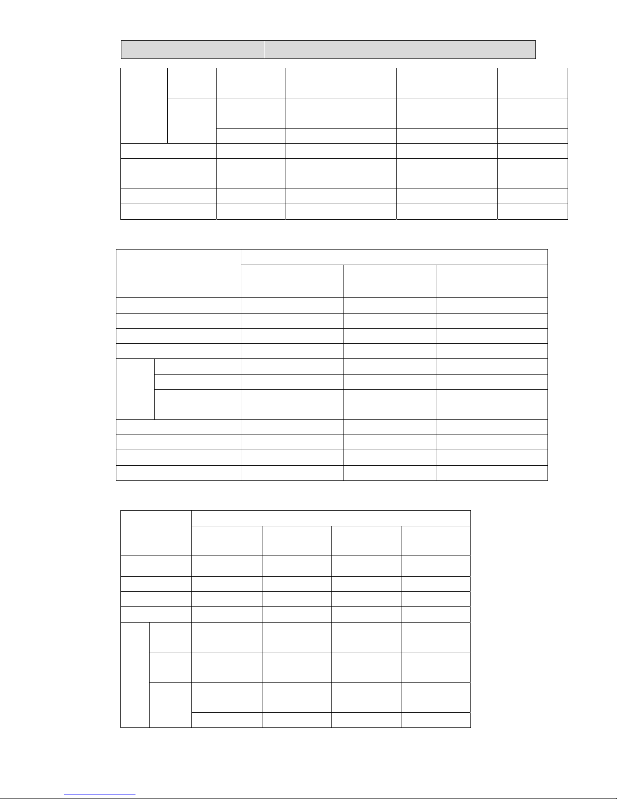
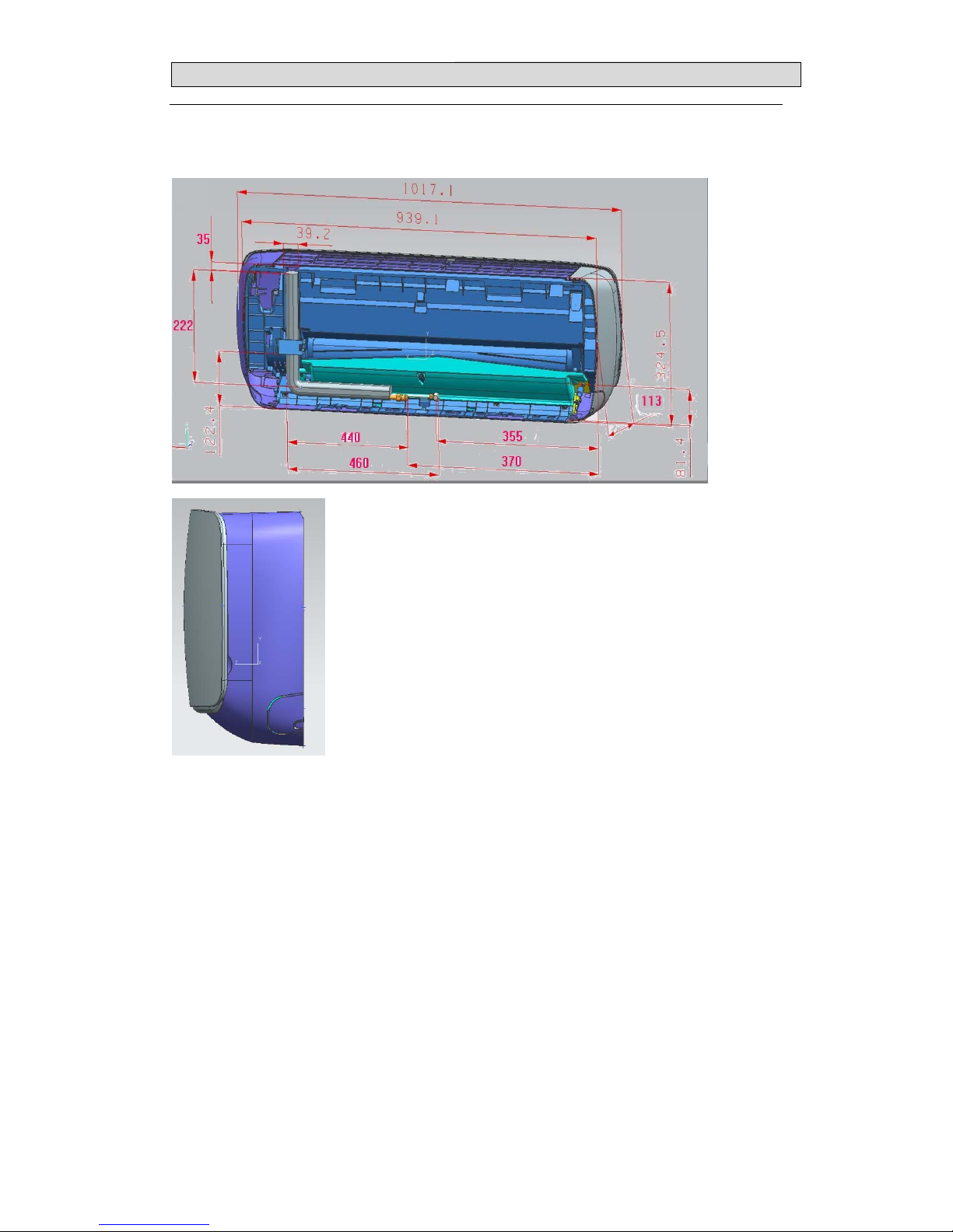
3-1. INDOOR
(MODEL: AMS-07UR4SNVG4 AMS-09UR4SNVG AMS-12UR4SNVG4(VT4、VL4、
VQ4、UP4、UL4、UQ4、NS4、ZC4、ZA4、NT4、NK4、NM4、VM4)
23mm631mm
94mm
190mm
250mm
750mm
50mm
50mm
50mm
65mm
Page 20
33.. OOUUTTLLIINNEESS AANNDD DDIIMMEENNSSIIOO
18
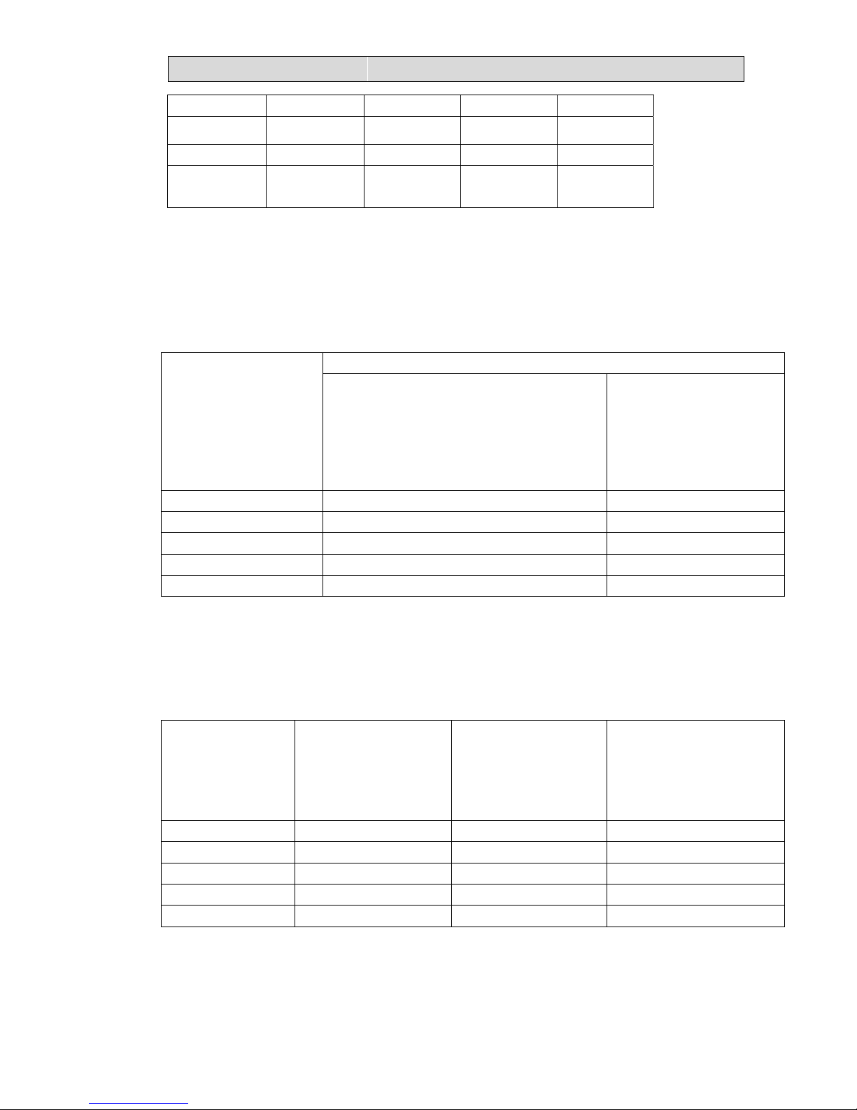
MODEL: AMS-18UR4SV(VG4/VL4/VT4/UP4/UL4/UQ4/VQ4/NT4/NK4/NM4)
50mm
50mm
50mm
313
203
920
Page 21
33.. OOUUTTLLIINNEESS AANNDD DDIIMMEENNSSIIOO
19
AMS-09/12UR4SPSC4
Page 22
33.. OOUUTTLLIINNEESS AANNDD DDIIMMEENNSSIIOO
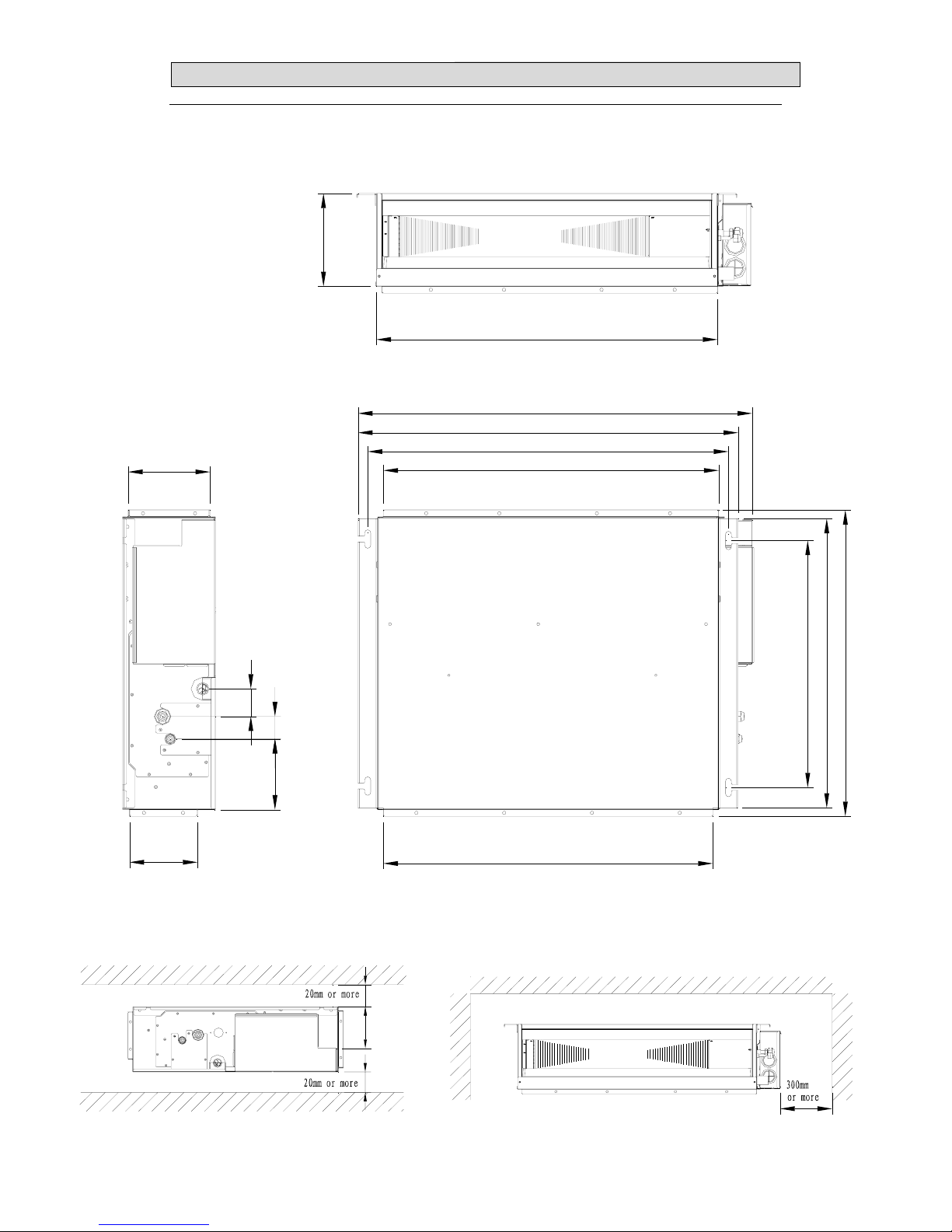
20
(MODEL: AMD-09UX4SJD/ AMD-12UX4SJD/AMD-18UX4SD)
47
57
508
740
780
808
595
630.2
740
190
688
676
140
168.4
145.5
122
Page 23
33.. OOUUTTLLIINNEESS AANNDD DDIIMMEENNSSIIOO
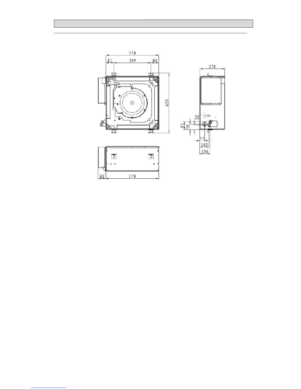
21
(MODEL: AMC-12UX4SAA/ AMC-18UX4SAA)
Page 24
33.. OOUUTTLLIINNEESS AANNDD DDIIMMEENNSSIIOO
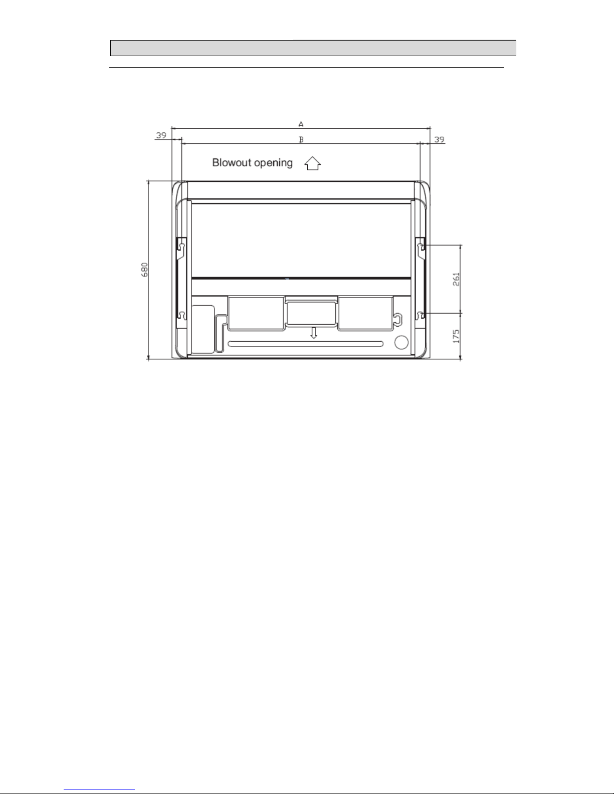
22
(MODEL: AMV-12UR4SA/ AMV -18UR4SA)
A=990,B=912
Page 25
33.. OOUUTTLLIINNEESS AANNDD DDIIMMEENNSSIIOO
23
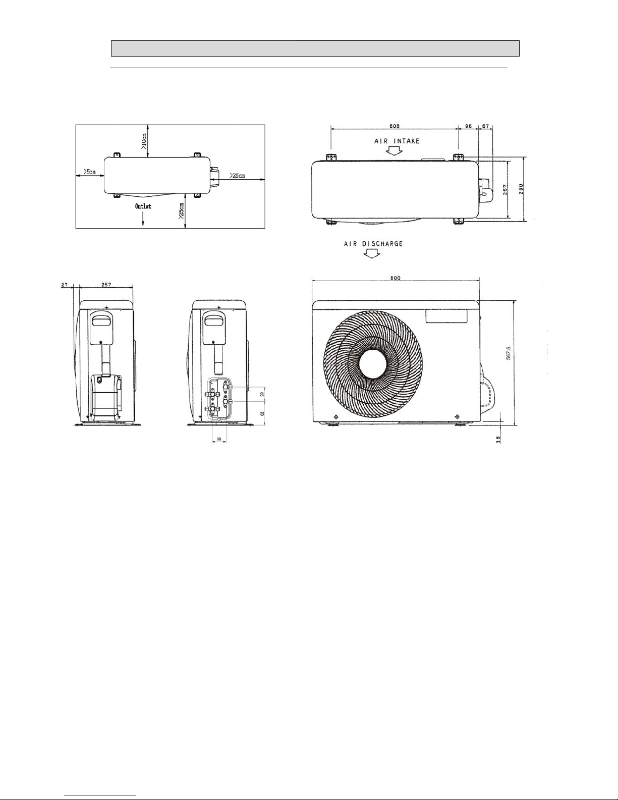
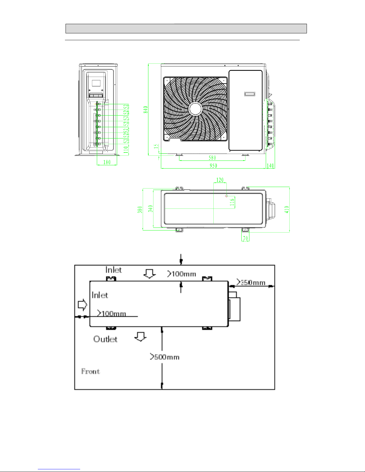
3-2.OUTDOOR
(MODEL: AMW2-16U4SGC1、AMW2-16U4SGD1)
Page 26
33.. OOUUTTLLIINNEESS AANNDD DDIIMMEENNSSIIOO
24
MODEL: AMW2-20U4SNC1、 AMW2-20U4SZD1,
Page 27
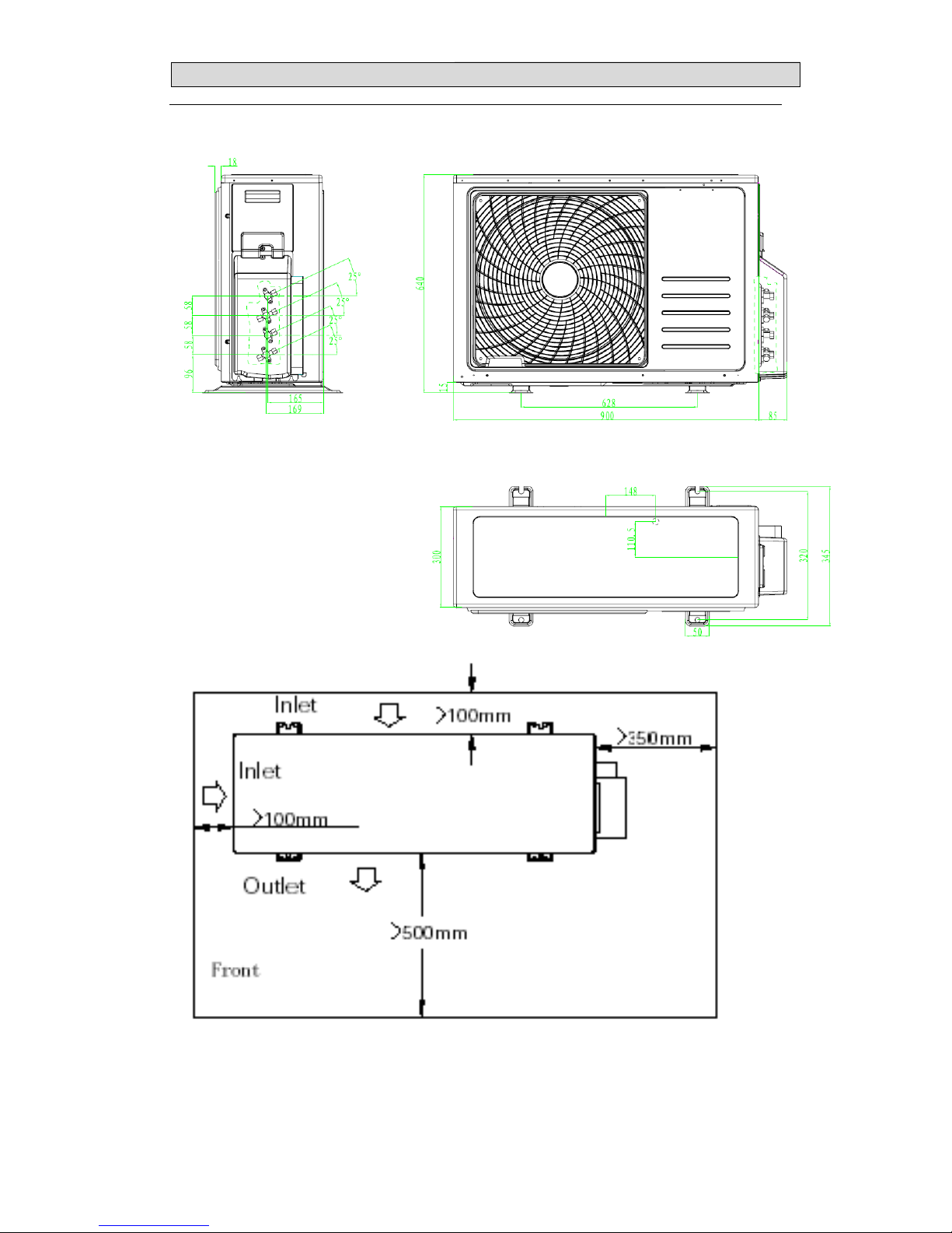
33.. OOUUTTLLIINNEESS AANNDD DDIIMMEENNSSIIOO
25
AMW3-20U4SZD 、AMW3-24U4SZD、AMW3-20U4SZD1
Page 28
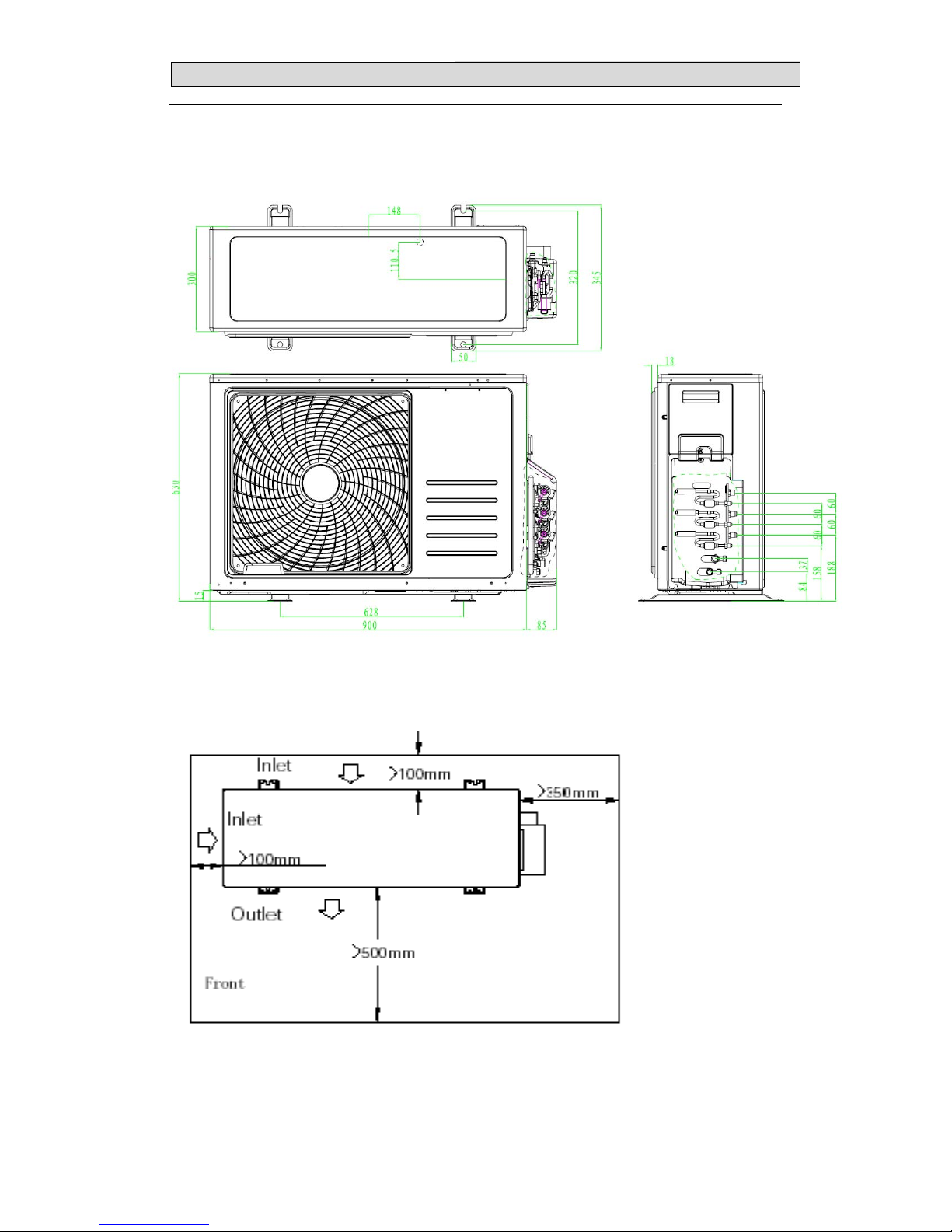
33.. OOUUTTLLIINNEESS AANNDD DDIIMMEENNSSIIOO
26
MODEL: AMW3-24U4SKC、AMW3-24U4SAD1
Page 29
33.. OOUUTTLLIINNEESS AANNDD DDIIMMEENNSSIIOO
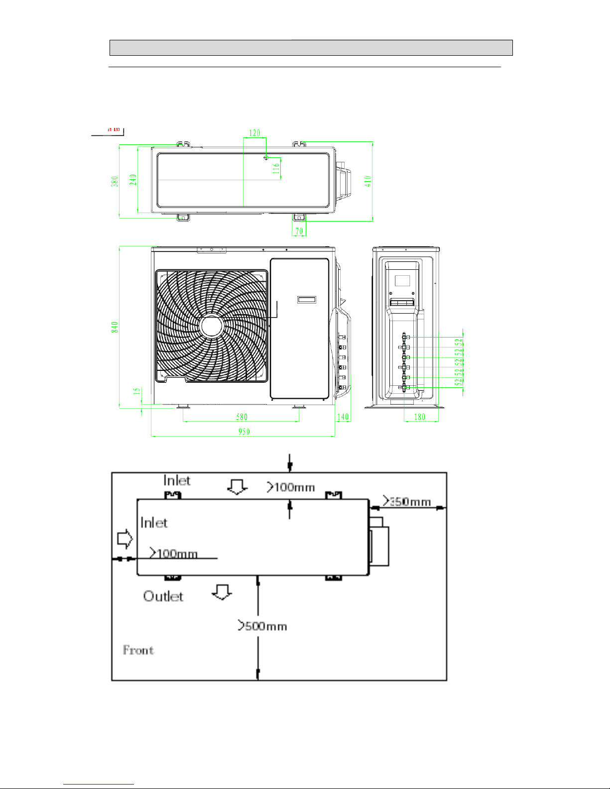
27
AMW4-28U4SKC AMW4-36U4SAC、AMW4-28U4SAD1,AMW4-36U4SAD1
Page 30
44.. RREEFFRRIIGGEERRAANNTT FFLLOOWW DDIIAAGGRRAAM
M
28
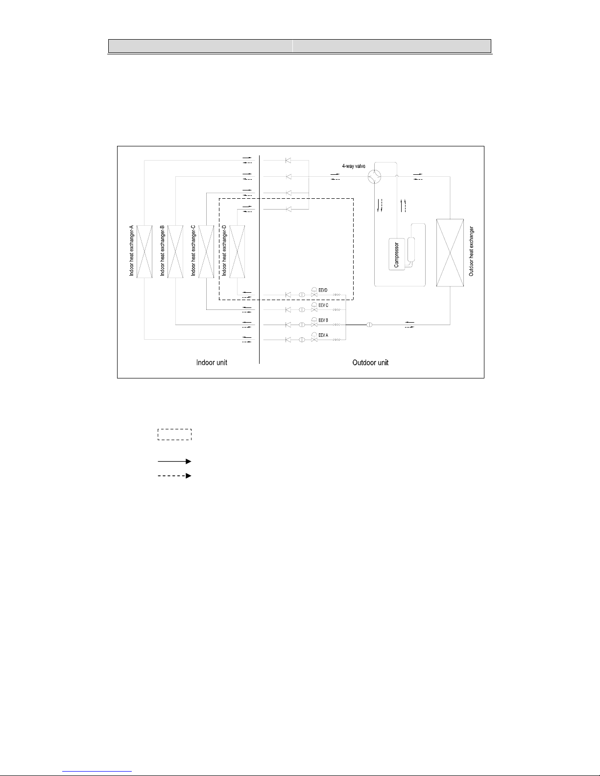
4-1. Refrigerant flow diagram :
MODEL:AMW3-24U4SKC、AMW4-28U4SKC、AMW4-36U4SAC、AMW3-24U4SAD1、
AMW4-28U4SAD1, AMW4-36U4SAD1
Filter
机
B
机A
机A
机
C
机B
机D
机
C
机
D
Remark: The part is only for AMW4-28U4SKC、AMW4-36U4SAC、
AMW4-36U4SAD1
COOLING CYCLE
HEATING CYCLE
Page 31

44.. RREEFFRRIIGGEERRAANNTT FFLLOOWW DDIIAAGGRRAAM
M
29
MODEL:AMW3-24U4SZD 、AMW3-20U4SZD,AMW3-20U4SZD1
Page 32

44.. RREEFFRRIIGGEERRAANNTT FFLLOOWW DDIIAAGGRRAAM
M
30
MODEL: AMW2-16U4SGC1、AMW2-20U4SNC1、AMW2-16U4SGD1、MW2-20U4SZD1
EEV B
EEV A
4-way valve
Filter
机
B
机
A
机
A
机
B
Filter
Page 33

44.. RREEFFRRIIGGEERRAANNTT FFLLOOWW DDIIAAGGRRAAM
M
31
4.2 Evacuation procedures:
EVACUATION PROCEDURES
Connect the refrigerant pipes (both the liquid an
d
g
as pipes) between the indoor and the outdoor units.
Remove service port cap of the stop valve A and connect gage manifold valve and vacuu
m
p
ump to it.
Run the vacuum pump for more than 15 minutes and at this time confirm that the pressure
gage indicates -0.1Mpa(-76 cmHg).
Stop pump and keep the pressure for one or two minutes. Make sure the pressure is no
change(if the pressure is changed to high, there is some leakage for the pipe connection).
Remove gage manifold valve quickly from the service port of the stop valve A.
full open the stop valves A on gas and liquid pipe sides.
T ot al pi pe len gth is in the range :
N
o gas charge is needed
T ot al pipe length exceeding the limit:
Charge the prescribed amount of gas.
Tighten the cap to the service port to obtain the initial status.
Retighten the cap.
Leak test
Repeat the steps above for other valves(B\C\D), be sure all refrigerant pipes are
connected and evacuated, and all valves are full opend.
Page 34

44.. RREEFFRRIIGGEERRAANNTT FFLLOOWW DDIIAAGGRRAAM
M
32
4-3. Evacuation direction:
MAX. Refrigerant pipe length and height difference:
Model
AMW3-20U4SZD
AMW3-24U4SZD
AMW3-24U4SKC
AMW4-28U4SKC
AMW4-36U4SAC
AMW3-24U4SAD1
AMW4-28U4SAD1
AMW4-36U4SAD1
AMW2-20U4SNC1
AMW2-16U4SGC1
AMW2-16U4SGD1
AMW2-20U4SZD1
AMW3-20U4SZD1
Pipe length per. Indoor unit(a/b/c/d) 25m 20m
Total pipe length for multi-system (a+b+c+d) 60m 40m
Height difference (I.D ~ O.D) 15m 10m
Height difference (I.D ~ I.D) 7.5m 7.5m
*Do your best to reduce the pipe length. Long pipe may cause capacity of the indoor unit incline.
Page 35

44.. RREEFFRRIIGGEERRAANNTT FFLLOOWW DDIIAAGGRRAAM
M
33
Outdoor unit precharged
Total refrigerant pipe length
0m~20m 20m~60m
AMW3-24U4SKC 2100g 0g
Xg = 15g / m × (Total pipe length(m) - 20)
If gas pipe include 12.7,refrigerant piping
length 20g/m
AMW4-28U4SKC 2400g 0g
AMW4-36U4SAC 2600g 0g
AMW3-24U4SZD 1750g 0g
AMW3-20U4SZD 1600g 0g
AMW3-24U4SAD1 2200g 0g
AMW4-28U4SAD1 2600g 0g
AMW3-20U4SZD1 1750g 0g
AMW4-36U4SAD1 2600g 0g
Outdoor unit precharged
Total refrigerant pipe length
0m~15m 15m~40m
AMW2-20U4SNC1 1400g
0 Xg = 15g / m × (Total pipe length(m) - 15)
AMW2-16U4SGC1 1270g
AMW2-16U4SGD1 1270g
AMW2-20U4SZD1 1400g
Page 36

55.. EELLEECCTTRRIICCAALL DDAATTAA
34
5-1.Electrical wiring diagrams
INDOOR:
1) AMS-07UR4SNVG4(VT、VL、VQ、UP、UL、UQ、NS、ZC、ZA、NT、NK4、NM4、VM4)4
AMS-09UR4SNVG4(VT、VL、VQ、UP、UL、UQ、NS、ZC、ZA、 NT、NK4、NM4、VM4)4
AMS-12UR4SNVG4(VT、VL、VQ、UP、UL、UQ、NS、ZC、ZA 、NT、NK4、NM4、VM4)4
Page 37

55.. EELLEECCTTRRIICCAALL DDAATTAA
35
2) AMS-07/09/12UR4SG(NK/NM/VT/VQ)4
Page 38

55.. EELLEECCTTRRIICCAALL DDAATTAA
36
AMS-18UR4SV(VG4/VL4/VT4/UP4/UL4/UQ4/VQ4/NT4/NK4/NM4)
Page 39

55.. EELLEECCTTRRIICCAALL DDAATTAA
37
AMS-09UR4SPSC4 、AMS-12UR4SPSC4
Page 40

55.. EELLEECCTTRRIICCAALL DDAATTAA
38
3)AMD-09UX4SJD 、AMD-12UX4SJD 、AMD-18UX4SJD
Page 41

55.. EELLEECCTTRRIICCAALL DDAATTAA
39
4)AMC-12UX4SAA 、AMC-18UX4SAA
Page 42

55.. EELLEECCTTRRIICCAALL DDAATTAA
40
5)AMV-12UR4SA,AMV-18UR4SA
Page 43

55.. EELLEECCTTRRIICCAALL DDAATTAA
41
OUTDOOR:
1) AMW2-16U4SGC1
Page 44

55.. EELLEECCTTRRIICCAALL DDAATTAA
42
2)AMW2-20U4SNC1
Page 45

55.. EELLEECCTTRRIICCAALL DDAATTAA
43
3)AMW3-20U4SZD
Page 46

55.. EELLEECCTTRRIICCAALL DDAATTAA
44
4)AMW3-24U4SZD
Page 47

55.. EELLEECCTTRRIICCAALL DDAATTAA
45
5)AMW3-24U4SKC
Page 48

55.. EELLEECCTTRRIICCAALL DDAATTAA
46
6)AMW4-28U4SKC
Page 49

55.. EELLEECCTTRRIICCAALL DDAATTAA
47
7)AMW4-36U4SAC
Page 50

55.. EELLEECCTTRRIICCAALL DDAATTAA
48
8)AMW2-16U4SGD1
Page 51

55.. EELLEECCTTRRIICCAALL DDAATTAA
49
9)AMW2-20U4SZD1
Page 52

55.. EELLEECCTTRRIICCAALL DDAATTAA
50
10)AMW3-24U4SAD1、AMW4-28U4SAD1
Page 53

55.. EELLEECCTTRRIICCAALL DDAATTAA
51
11)AMW3-20U4SZD1
Page 54

55.. EELLEECCTTRRIICCAALL DDAATTAA
52
12)AMW4-36U4SAD1
Page 55

55.. EELLEECCTTRRIICCAALL DDAATTAA
53
5-2. Electric control
1. Indoor control board for indoor unit
1)
AMS-07/09/12UR4SN(VG/VT/VL/VQ/UP/UL/UQ/NS/ZC/ZA/NT/NK/NM/VM)4
2) AMS-07/09/12UR4SG(NK/NM/VT/VQ)4
Page 56

55.. EELLEECCTTRRIICCAALL DDAATTAA
54
3)AMS-18U4SV(VG/VQ/VL/VT/UP/UL/UQ/NT/NK/NM)4
4)AMS-09UR4SPSC4 、AMS-12UR4SPSC4
Page 57

55.. EELLEECCTTRRIICCAALL DDAATTAA
55
5) AMD-09UX4SJD 、 AMD-12UX4SD 、 AMD-18UX4SJD, AMC-12UX4SAA 、 AMC-18UX4SAA,
AMV-12UR4SA,AMV-18UR4SA
Page 58

55.. EELLEECCTTRRIICCAALL DDAATTAA
56
2.Control board for outdoor unit
1)FILTER BOARD (AMW3-24U4SKC、AMW4-28U4SKC AMW4-36U4SAC )
AC N IN
To Indoor N
To Indoor L
AC L IN
AC N OUT
AC L OUT
3.15 /250
To Control Board
+12V
GND
Fan Motor Drving
4-Way Drving
Heater N out
Heater L out
2)CONTROL BOARD(AMW3-24U4SKC、AMW4-28U4SKC AMW4-36U4SAC AMW4-36U4SAD1)
Page 59

55.. EELLEECCTTRRIICCAALL DDAATTAA
57
CONTROL BOARD(AMW3-20U4SZD AMW3-24U4SZD AMW3-20U4SZD1)
CONTROL BOARD(AMW2-16U4SGC1 AMW2-20U4SNC1)
Communication N
TO Indoor unit B
TO Indoor unit A
Overload
Protection
Gas B Sensor
Liquid A/B &
Gas A Sensor
Outdoor/Suction/
Condensor Sensor
Compressor
Discharge Sensor
A VALVE DRVING
B VALVE
DRVING
DC-
DC+
To IPM Board
(Power)
To IPM Board
(Communication)
4-Way Valve
AC Fan Motor
AC N OUT
AC L OUT
Earth Wire
AC N IN
AC L IN
Page 60

55.. EELLEECCTTRRIICCAALL DDAATTAA
58
CONTROL BOARD(AMW2-16U4SGD1、AMW2-20U4SZD1 )
CONTROL BOARD(AMW2-16U4SGD1、AMW2-20U4SZD1 )
Page 61

55.. EELLEECCTTRRIICCAALL DDAATTAA
59
3)IPM BOARD
(AMW3-24U4SKC、AMW4-28U4SKC AMW4-36U4SAC AMW3-20U4SZD AMW3-24U4SZD 、
AMW3-24U4SAD1、AMW4-28U4SAD1)
To M a in C o ntrol
Board
To Compressor U
To Compressor V
To Compressor W
IPM Pow e r
To Ele ctr o lytic
Capac itor -
To Electrolytic
Capacitor +
To Electrolytic
Capacitor +
To PFC
Inductor-2
To PFC
Inductor-1
ac N in
ac L in
Page 62

55.. EELLEECCTTRRIICCAALL DDAATTAA
60
IPM Board(AMW2-16U4SGC1 AMW2-20U4SNC1、AMW2-16U4SGD1、AMW2-20U4SZD1)
To Compressor U
To Compressor V
To Compressor W
To Electrolytic
Capacito r +
To Electrolytic
Capacitor +
To M ain Control
Board
IPM Po wer
To Electrolytic
Capacitor -
To PFC Inductor-2
To PFC Inductor-1
AC N IN
AC L IN
Page 63

55.. EELLEECCTTRRIICCAALL DDAATTAA
61
5-3. Sensor parameter
1. THE PARAMETER OF OUTDOOR COMPRESSOR DISCHARGE TEMPERATURE SENSOR:
(R
0
=187.25K±6.3%;R
100
=3.77K±2.5K;B0/100=3979K±1%)
T [ ℃ ]
Rmin [ KΩ ] Rnom [ KΩ ] Rmax [ KΩ ] DR(MIN)% DR(MAX)%
-30 908.2603 985.5274 1065.1210 -7.84 7.47
-29 855.3955 927.6043 1001.9150 -7.78 7.42
-28 805.9244 873.4324 924.8368 -7.73 5.56
-27 759.6097 822.7471 887.5944 -7.67 7.31
-26 716.2320 775.3041 835.9165 -7.62 7.25
-25 675.5881 730.8775 787.5529 -7.56 7.20
-24 637.4902 689.2583 742.2720 -7.51 7.14
-23 601.7645 650.2533 699.8601 -7.46 7.09
-22 568.2499 613.6835 660.1191 -7.40 7.03
-21 536.7970 579.3832 622.8658 -7.35 6.98
-20 507.2676 547.1989 587.9307 -7.30 6.93
-19 497.5332 516.9882 555.1565 -3.76 6.88
-18 453.4748 488.6192 524.3977 -7.19 6.82
-17 428.9819 461.9693 495.5191 -7.14 6.77
-16 405.9517 436.9251 486.3954 -7.09 10.17
-15 384.2888 413.3808 442.9105 -7.04 6.67
-14 363.9047 391.2386 418.9563 -6.99 6.62
-13 344.7169 370.4072 396.4325 -6.94 6.56
-12 326.6497 350.8019 375.2461 -6.88 6.51
-11 309.6286 332.3441 355.3104 -6.83 6.46
-10 293.5903 314.9620 336.5448 -6.79 6.41
-9 278.4719 298.5822 318.3744 -6.74 6.22
-8 264.2156 283.1464 302.2294 -6.69 6.31
-7 250.7678 268.5936 286.5448 -6.64 6.26
-6 238.0783 254.8686 271.7603 -6.59 6.22
-5 226.1003 241.9200 257.8193 -6.54 6.17
-4 214.7903 229.6997 244.6593 -6.49 6.11
-3 204.1073 218.1630 232.2612 -6.44 6.07
-2 194.0135 207.2681 220.5495 -6.39 6.02
-1 184.4732 196.9759 209.4913 -6.35 5.97
0 175.4533 187.2500 199.0468 -6.30 5.93
1 166.8952 178.0255 189.1529 -6.25 5.88
2 158.8023 169.3067 179.8058 -6.20 5.84
3 151.1467 161.0633 170.9724 -6.16 5.80
4 143.9026 153.2667 162.6216 -6.11 5.75
5 137.0455 145.8905 154.7246 -6.06 5.71
6 130.5528 138.9097 147.2544 -6.02 5.67
7 124.4033 132.3011 140.1856 -5.97 5.62
8 118.5769 126.0429 133.4946 -5.92 5.58
9 113.0550 120.1146 127.1591 -5.88 5.54
Page 64

55.. EELLEECCTTRRIICCAALL DDAATTAA
62
T [ ℃ ]
Rmin [ KΩ ] Rnom [ KΩ ] Rmax [ KΩ ] DR(MIN)% DR(MAX)%
10 107.8202 114.4973 121.1586 -5.83 5.50
11 102.8560 109.1728 115.4734 -5.79 5.46
12 98.1470 104.1246 110.0855 -5.74 5.41
13 93.6787 99.3367 104.9778 -5.70 5.37
14 89.4378 94.7946 100.1342 -5.65 5.33
15 85.4114 90.4842 95.5398 -5.61 5.29
16 81.5875 86.3926 91.1805 -5.56 5.25
17 77.9551 82.5076 87.0430 -5.52 5.21
18 74.5034 78.8177 83.1150 -5.47 5.17
19 71.2227 75.3122 79.3848 -5.43 5.13
20 68.1036 71.9808 75.8414 -5.39 5.09
21 65.1373 68.8141 72.4746 -5.34 5.05
22 62.3155 65.8032 69.2746 -5.30 5.01
23 59.6306 62.9395 66.2324 -5.26 4.97
24 57.0752 60.2152 63.3395 -5.21 4.93
25 54.6424 57.6227 60.5877 -5.17 4.89
26 52.3258 55.1551 57.9695 -5.13 4.85
27 50.1192 52.8058 55.4778 -5.09 4.82
28 48.0168 50.5684 53.1058 -5.05 4.78
29 46.0133 48.4371 50.8472 -5.00 4.74
30 44.1034 46.4046 48.6960 -4.96 4.71
31 42.2825 44.4711 46.6466 -4.92 4.66
32 40.5458 42.6261 44.6937 -4.88 4.63
33 38.8891 40.8668 42.8323 -4.84 4.59
34 37.3084 39.1890 41.0576 -4.80 4.55
35 35.7998 37.5883 39.3653 -4.76 4.51
36 34.3596 36.0609 37.7511 -4.72 4.48
37 32.9844 34.6030 36.2109 -4.68 4.44
38 31.6710 33.2113 34.7412 -4.64 4.40
39 30.4164 31.8823 33.3383 -4.60 4.37
40 29.2176 30.6130 31.9988 -4.56 4.33
41 28.0718 29.4004 30.7197 -4.52 4.29
42 26.9765 28.2417 29.4979 -4.48 4.26
43 25.9293 27.1342 28.3306 -4.44 4.22
44 24.9277 26.0755 27.2150 -4.40 4.19
45 23.9697 25.0632 26.1488 -4.36 4.15
46 23.0530 24.0950 25.1293 -4.32 4.12
47 22.1757 23.1688 24.1545 -4.29 4.08
48 21.3360 22.2826 23.2221 -4.25 4.05
49 20.5321 21.4345 22.3301 -4.21 4.01
50 19.7623 20.6226 21.4766 -4.17 3.98
51 19.0261 19.8468 20.6612 -4.14 3.94
52 18.3211 19.1040 19.8808 -4.10 3.91
53 17.6458 18.3926 19.1338 -4.06 3.87
Page 65

55.. EELLEECCTTRRIICCAALL DDAATTAA
63
T [ ℃ ]
Rmin [ KΩ ] Rnom [ KΩ ] Rmax [ KΩ ] DR(MIN)% DR(MAX)%
54 16.9986 17.7113 18.4185 -4.02 3.84
55 16.3784 17.0537 17.7335 -3.96 3.83
56 15.7839 16.4332 17.0774 -3.95 3.77
57 15.2139 15.8338 16.4488 -3.92 3.74
58 14.6673 15.2592 15.8464 -3.88 3.71
59 14.1430 14.7083 15.2690 -3.84 3.67
60 13.6400 14.1799 14.7154 -3.81 3.64
61 13.1573 13.6730 14.1846 -3.77 3.61
62 12.6941 13.1868 13.6756 -3.74 3.57
63 12.2494 12.7202 13.1872 -3.70 3.54
64 11.8224 12.2723 12.7186 -3.67 3.51
65 11.4124 11.8424 12.2690 -3.63 3.48
66 11.0185 11.4295 11.8373 -3.60 3.45
67 10.6401 11.0331 11.4230 -3.56 3.41
68 10.2765 10.6522 11.0251 -3.53 3.38
69 9.9271 10.2863 10.6429 -3.49 3.35
70 9.5912 9.9348 10.2756 -3.46 3.32
71 9.2682 9.5968 9.9231 -3.42 3.29
72 8.9576 9.2720 9.5841 -3.39 3.26
73 8.6589 8.9597 9.2583 -3.36 3.23
74 8.3716 8.6594 8.9451 -3.32 3.19
75 8.0951 8.3705 8.6440 -3.29 3.16
76 7.8290 8.0926 8.3544 -3.26 3.13
77 7.5730 7.8252 8.0758 -3.22 3.10
78 7.3264 7.5679 7.8078 -3.19 3.07
79 7.0891 7.3202 7.5499 -3.16 3.04
80 6.8605 7.0818 7.3018 -3.12 3.01
81 6.6403 6.8522 7.0629 -3.09 2.98
82 6.4282 6.6311 6.8329 -3.06 2.95
83 6.2239 6.4182 6.6115 -3.03 2.92
84 6.0269 6.2131 6.3982 -3.00 2.89
85 5.8371 6.0154 6.1928 -2.96 2.86
86 5.6542 5.8249 5.9949 -2.93 2.84
87 5.4777 5.6413 5.8042 -2.90 2.81
88 5.3076 5.4644 5.6205 -2.87 2.78
89 5.1435 5.2937 5.4433 -2.84 2.75
90 4.9853 5.1292 5.2726 -2.81 2.72
91 4.8326 4.9705 5.1079 -2.77 2.69
92 4.6852 4.8174 4.9492 -2.74 2.66
93 4.5430 4.6697 4.7960 -2.71 2.63
94 4.4058 4.5272 4.6483 -2.68 2.61
95 4.2733 4.3896 4.5058 -2.65 2.58
96 4.1453 4.2568 4.3683 -2.62 2.55
97 4.0218 4.1287 4.2355 -2.59 2.52
Page 66

55.. EELLEECCTTRRIICCAALL DDAATTAA
64
T [ ℃ ]
Rmin [ KΩ ] Rnom [ KΩ ] Rmax [ KΩ ] DR(MIN)% DR(MAX)%
98 3.9024 4.0049 4.1074 -2.56 2.50
99 3.7872 3.8854 3.9837 -2.53 2.47
100 3.6758 3.7700 3.8643 -2.50 2.44
101 3.5661 3.6585 3.7512 -2.53 2.47
102 3.4601 3.5509 3.6419 -2.56 2.50
103 3.3577 3.4468 3.5362 -2.59 2.53
104 3.2588 3.3463 3.4341 -2.61 2.56
105 3.1632 3.2491 3.3353 -2.64 2.58
106 3.0708 3.1551 3.2398 -2.67 2.61
107 2.9816 3.0643 3.1475 -2.70 2.64
108 2.8953 2.9765 3.0582 -2.73 2.67
109 2.8118 2.8915 2.9717 -2.76 2.70
110 2.7311 2.8093 2.8881 -2.78 2.73
111 2.6531 2.7299 2.8072 -2.81 2.75
112 2.5776 2.6530 2.7289 -2.84 2.78
113 2.5046 2.5785 2.6531 -2.87 2.81
114 2.4340 2.5065 2.5798 -2.89 2.84
115 2.3656 2.4368 2.5087 -2.92 2.87
116 2.2995 2.3693 2.4400 -2.95 2.90
117 2.2354 2.3040 2.3733 -2.98 2.92
118 2.1734 2.2407 2.3088 -3.00 2.95
119 2.1134 2.1795 2.2463 -3.03 2.97
120 2.0553 2.1201 2.1858 -3.06 3.01
121 1.9991 2.0626 2.1271 -3.08 3.03
122 1.9446 2.0070 2.0702 -3.11 3.05
123 1.8918 1.9530 2.0151 -3.13 3.08
124 1.8406 1.9007 1.9617 -3.16 3.11
125 1.7911 1.8500 1.9099 -3.18 3.14
126 1.7430 1.8009 1.8597 -3.22 3.16
127 1.6965 1.7533 1.8110 -3.24 3.19
128 1.6514 1.7071 1.7638 -3.26 3.21
129 1.6076 1.6623 1.7180 -3.29 3.24
130 1.5652 1.6189 1.6736 -3.32 3.27
Page 67

55.. EELLEECCTTRRIICCAALL DDAATTAA
65
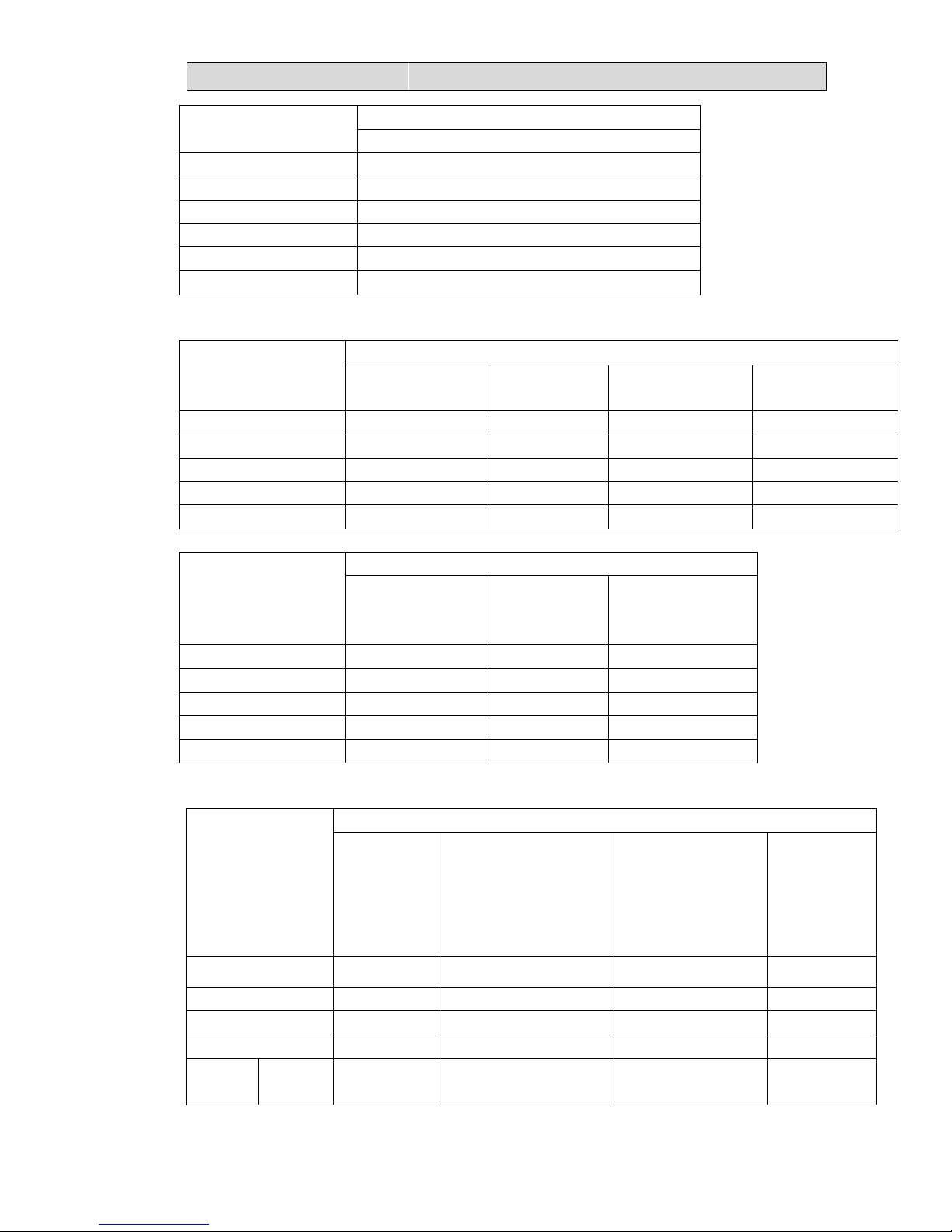
2. THE PARAMETER OF THE OTHER SENSOR IN INDOOR AND OUTDOOR UNIT:(R0=15K±2%;
B0/100=3450K±2%)
T [ ℃ ]
Rmin [ KΩ ] Rnom [ KΩ ] Rmax [ KΩ ] DR(MIN)% DR(MAX)%
-30 60.78 64.77 68.99 -6.16 6.12
-29 57.75 61.36 65.16 -5.88 5.83
-28 54.89 58.15 61.58 -5.61 5.57
-27 52.19 55.14 58.23 -5.35 5.31
-26 49.63 52.30 55.08 -5.11 5.05
-25 47.21 49.62 52.13 -4.86 4.81
-24 44.92 47.10 49.37 -4.63 4.60
-23 42.76 44.73 46.78 -4.40 4.38
-22 40.71 42.49 44.34 -4.19 4.17
-21 38.77 40.38 42.05 -3.99 3.97
-20 36.93 38.39 39.90 -3.80 3.78
-19 35.18 36.51 37.87 -3.64 3.59
-18 33.53 34.74 35.97 -3.48 3.42
-17 31.96 33.06 34.17 -3.33 3.25
-16 30.48 31.47 32.49 -3.15 3.14
-15 29.07 29.97 30.89 -3.00 2.98
-14 27.73 28.56 29.39 -2.91 2.82
-13 26.46 27.22 27.98 -2.79 2.72
-12 25.26 25.95 26.64 -2.66 2.59
-11 24.11 24.75 25.38 -2.59 2.48
-10 23.03 23.61 24.19 -2.46 2.40
-9 21.99 22.53 23.06 -2.40 2.30
-8 21.01 21.51 22.00 -2.32 2.23
-7 20.08 20.54 20.99 -2.24 2.14
-6 19.19 19.62 20.04 -2.19 2.10
-5 18.35 18.74 19.14 -2.08 2.09
-4 17.55 17.92 18.29 -2.06 2.02
-3 16.78 17.13 17.48 -2.04 2.00
-2 16.06 16.38 16.71 -1.95 1.97
-1 15.36 15.67 15.98 -1.98 1.94
0 14.70 15.00 15.29 -2.00 1.90
1 14.08 14.36 14.64 -1.95 1.91
2 13.48 13.75 14.02 -1.96 1.93
3 12.91 13.17 13.43 -1.97 1.94
4 12.36 12.62 12.87 -2.06 1.94
5 11.85 12.09 12.34 -1.99 2.03
6 11.35 11.59 11.83 -2.07 2.03
7 10.88 11.11 11.35 -2.07 2.11
8 10.43 10.66 10.89 -2.16 2.11
9 9.999 10.230 10.450 -2.26 2.11
10 9.590 9.816 10.040 -2.30 2.23
11 9.199 9.422 9.647 -2.37 2.33
Page 68

55.. EELLEECCTTRRIICCAALL DDAATTAA
66
T [ ℃ ]
Rmin [ KΩ ] Rnom [ KΩ ] Rmax [ KΩ ] DR(MIN)% DR(MAX)%
12 8.826 9.047 9.269 -2.44 2.40
13 8.470 8.689 8.910 -2.52 2.48
14 8.129 8.347 8.567 -2.61 2.57
15 7.804 8.021 8.240 -2.71 2.66
16 7.493 7.709 7.928 -2.80 2.76
17 7.196 7.412 7.630 -2.91 2.86
18 6.912 7.127 7.346 -3.02 2.98
19 6.640 6.855 7.074 -3.14 3.10
20 6.381 6.595 6.815 -3.24 3.23
21 6.132 6.347 6.567 -3.39 3.35
22 5.894 6.109 6.330 -3.52 3.49
23 5.667 5.882 6.103 -3.66 3.62
24 5.449 5.664 5.886 -3.80 3.77
25 5.240 5.456 5.678 -3.96 3.91
26 5.048 5.260 5.478 -4.03 3.98
27 4.864 5.072 5.286 -4.10 4.05
28 4.687 4.891 5.101 -4.17 4.12
29 4.517 4.717 4.924 -4.24 4.20
30 4.355 4.550 4.753 -4.29 4.27
31 4.198 4.390 4.589 -4.37 4.34
32 4.048 4.236 4.431 -4.44 4.40
33 3.904 4.089 4.280 -4.52 4.46
34 3.766 3.946 4.134 -4.56 4.55
35 3.663 3.810 3.994 -3.86 4.61
36 3.506 3.679 3.859 -4.70 4.66
37 3.383 3.552 3.729 -4.76 4.75
38 3.265 3.431 3.604 -4.84 4.80
39 3.152 3.314 3.484 -4.89 4.88
40 3.043 3.202 3.368 -4.97 4.93
41 2.938 3.094 3.257 -5.04 5.00
42 2.838 2.990 3.149 -5.08 5.05
43 2.741 2.890 3.046 -5.16 5.12
44 2.648 2.793 2.946 -5.19 5.19
45 2.558 2.701 2.850 -5.29 5.23
46 2.472 2.611 2.758 -5.32 5.33
47 2.389 2.525 2.669 -5.39 5.40
48 2.309 2.443 2.583 -5.49 5.42
49 2.232 2.363 2.500 -5.54 5.48
50 2.158 2.286 2.421 -5.60 5.58
51 2.087 2.212 2.344 -5.65 5.63
52 2.018 2.140 2.269 -5.70 5.69
53 1.952 2.072 2.198 -5.79 5.73
54 1.888 2.005 2.129 -5.84 5.82
55 1.827 1.941 2.062 -5.87 5.87
Page 69

55.. EELLEECCTTRRIICCAALL DDAATTAA
67
T [ ℃ ]
Rmin [ KΩ ] Rnom [ KΩ ] Rmax [ KΩ ] DR(MIN)% DR(MAX)%
56 1.767 1.880 1.998 -6.01 5.91
57 1.710 1.820 1.936 -6.04 5.99
58 1.655 1.763 1.876 -6.13 6.02
59 1.602 1.707 1.818 -6.15 6.11
60 1.551 1.654 1.762 -6.23 6.13
61 1.502 1.602 1.709 -6.24 6.26
62 1.452 1.553 1.657 -6.50 6.28
63 1.409 1.505 1.606 -6.38 6.29
64 1.364 1.458 1.558 -6.45 6.42
65 1.322 1.413 1.511 -6.44 6.49
66 1.280 1.370 1.466 -6.57 6.55
67 1.241 1.328 1.422 -6.55 6.61
68 1.202 1.288 1.379 -6.68 6.60
69 1.165 1.249 1.339 -6.73 6.72
70 1.129 1.211 1.299 -6.77 6.77
71 1.095 1.175 1.261 -6.81 6.82
72 1.061 1.140 1.224 -6.93 6.86
73 1.029 1.106 1.188 -6.96 6.90
74 0.9977 1.073 1.153 -7.02 6.94
75 0.9676 1.041 1.120 -7.05 7.05
76 0.9385 1.011 1.088 -7.17 7.08
77 0.9104 0.9810 1.056 -7.20 7.10
78 0.8833 0.9523 1.026 -7.25 7.18
79 0.8570 0.9246 0.9971 -7.31 7.27
80 0.8316 0.8977 0.9687 -7.36 7.33
81 0.8071 0.8717 0.9412 -7.41 7.38
82 0.7834 0.8466 0.9146 -7.47 7.43
83 0.7604 0.8223 0.8888 -7.53 7.48
84 0.7382 0.7987 0.8639 -7.57 7.55
85 0.7167 0.7759 0.8397 -7.63 7.60
86 0.6958 0.7537 0.8161 -7.68 7.65
87 0.6755 0.7322 0.7933 -7.74 7.70
88 0.6560 0.7114 0.7712 -7.79 7.75
89 0.6371 0.6913 0.7498 -7.84 7.80
90 0.6188 0.6718 0.7291 -7.89 7.86
91 0.6011 0.6530 0.7051 -7.95 7.39
92 0.5840 0.6348 0.6897 -8.00 7.96
93 0.5674 0.6171 0.6709 -8.05 8.02
94 0.5514 0.6000 0.6527 -8.10 8.07
95 0.5359 0.5835 0.6350 -8.16 8.11
96 0.5209 0.5675 0.6179 -8.21 8.16
97 0.5064 0.5519 0.6014 -8.24 8.23
98 0.4923 0.5369 0.5853 -8.31 8.27
99 0.4787 0.5224 0.5698 -8.37 8.32
Page 70

55.. EELLEECCTTRRIICCAALL DDAATTAA
68
T [ ℃ ]
Rmin [ KΩ ] Rnom [ KΩ ] Rmax [ KΩ ] DR(MIN)% DR(MAX)%
100 0.4655 0.5083 0.5547 -8.42 8.36
101 0.4528 0.4946 0.5401 -8.45 8.42
102 0.4404 0.4814 0.5259 -8.52 8.46
103 0.4284 0.4685 0.5121 -8.56 8.51
104 0.4168 0.4561 0.4988 -8.62 8.56
105 0.4056 0.4440 0.4859 -8.65 8.62
106 0.3947 0.4323 0.4733 -8.70 8.66
107 0.3841 0.4210 0.4611 -8.76 8.70
108 0.3739 0.4100 0.4493 -8.80 8.75
109 0.3640 0.3993 0.4379 -8.84 8.81
110 0.3544 0.3890 0.4267 -8.89 8.84
111 0.3450 0.3789 0.4159 -8.95 8.90
112 0.3360 0.3692 0.4055 -8.99 8.95
113 0.3272 0.3597 0.3953 -9.04 9.01
114 0.3187 0.3505 0.3854 -9.07 9.06
115 0.3104 0.3416 0.3758 -9.13 9.10
116 0.3024 0.3330 0.3665 -9.19 9.14
117 0.2947 0.3246 0.3574 -9.21 9.18
118 0.2871 0.3164 0.3468 -9.26 8.77
119 0.2798 0.3085 0.3401 -9.30 9.29
120 0.2727 0.3008 0.33 -9.34 9.34
Page 71

66.. CCOONNTTRROOLL MMOODDEEL
L
66
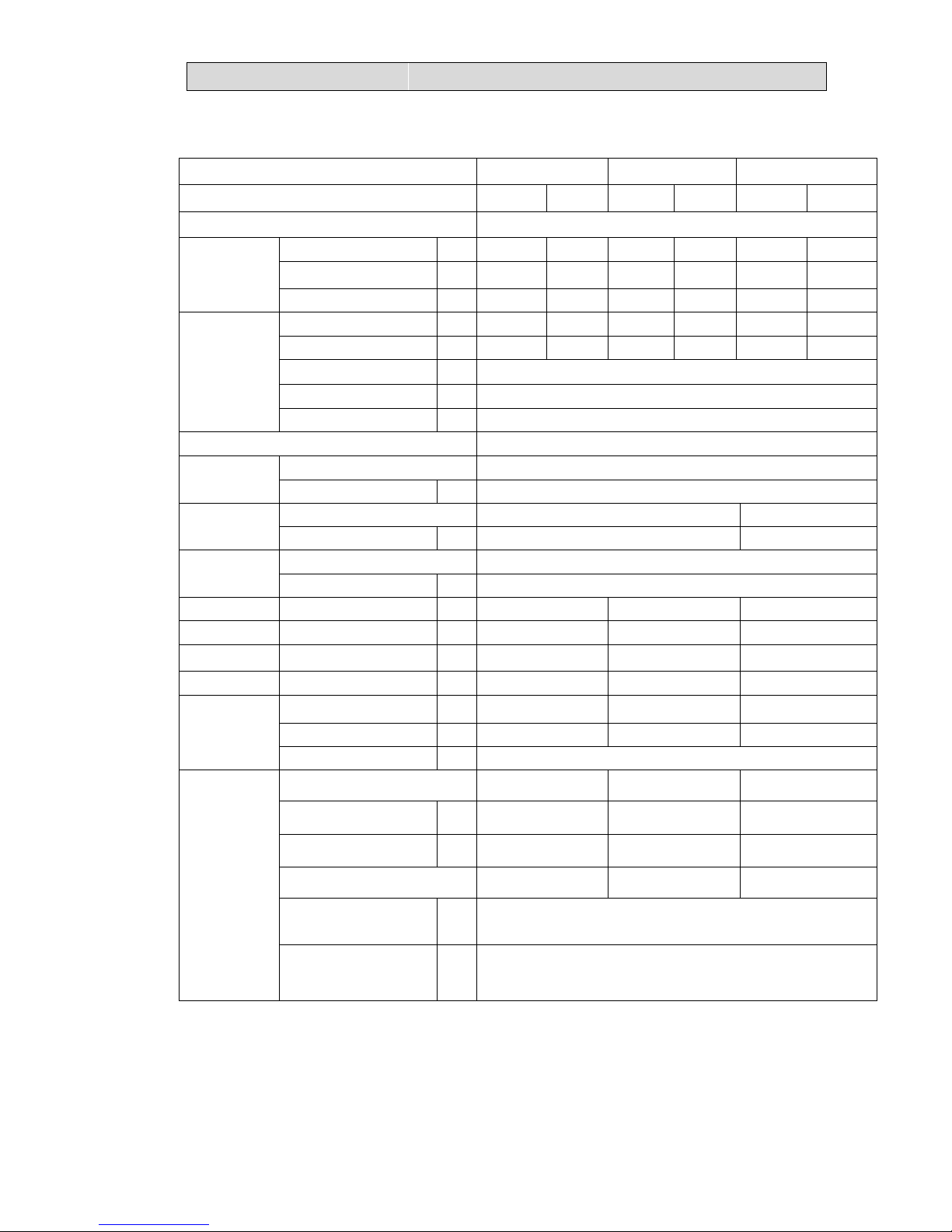
6-1 Indoor control mode
1.Major general technical parameters
1 Conditionings for operation: Ambient temperatures: (-15 - +45 ), relative humidity ℃
(45 - 85%).
2 Remote receiver distance: 8 m.
3 Remote receiver angle: Less than 80 degrees.
4 Temperature control accuracy: ±1 . ℃
5 Time error: Less than 1%.
6 The power supply for the air conditioner is a.c 220V~240V, 50Hz, with its fluctuation in
the range of (176V – 264 V).
2. Functions of the controller
. Control function
3.1Emergency switch
1. When the machine is turned OFF, by press and hold the emergency switch for 5
seconds, with 3 beeps , the indoor unit would turn to emergency run. In such station,
machine would be forced to turn to cooling operation with the indoor fan speed being set at
high speed, the flaps sweeping and the air conditioner’s operation is irrelevant with room
temperatures.
2. If a remote signal has been received during the emergency run, the machine will
operate upon the command of such a remote signal.
3.2 Operator-machine communication
The air conditioner has a thermal sensor to detect room temperatures. Some remote
controller is equipped with a thermal sensor (Such remote controller has the function of
man-machine communication. For details, refer to the section for the remote controller). In
addition, there is a thermal sensor at the indoor air inlet. In the case where the remote
controller is equipped with a thermal sensor, the default setting for room temperatures is
subject to the detection by the remote controller. The remote controller detects the room
temperature once every 20 seconds, and automatically transmits a signal at an interval of 3
minutes or when a change in the room temperature is detected. If the indoor control unit has
not received a remote signal for more than 10 minutes, the control function will be
automatically switched over to the thermal sensor on the indoor unit.
3.3 Timer function
1. Timer on: When set to start in a time by the remote controller, the air conditioner starts in
the timer on condition. When the set time is up, the air conditioner will turn on and operates
in the preset conditions after receiving a signal from the remote controller. If the air
conditioner has not received a signal from the remote controller when the set time is up, it
will automatically start and operate in the preset conditions.
2. Timer off: When set to stop in a set time by the remote controller, the air conditioner will
start in the timer off condition. When the set time is up, the air conditioner will turn off after
receiving a signal from the remote controller. If the air conditioner has not received a signal
from the remote controller when the set time is up, it will turn off automatically.
3. Neither the turning on nor turning off operation will cancel the timer function (Some
remote controller has a simple one-hour timer off function and excludes this operation).。
Page 72

66.. CCOONNTTRROOLL MMOODDEEL
L
67
3.4 Sleep
1. In the heating, cooling or dehumidifying mode, press the “Sleep” button on the remote
controller to start or cancel the sleep function in turn, and at the same time the sleep icon on
the display screen will be on or off accordingly.
2. In the heating mode, the set temperature will decrease automatically after the sleep
function is started.
3. In the cooling mode, the set temperature will rise automatically after the sleep function is
started.
4. In default, the setting is to cancel the sleep function. Turning off the unit will also cancel
the sleep function.
3.5 High efficient run function
In Cool, Dehumidification, Fan mode, press the "HIGH POWER " to enter the refrigeration
mode, set the temperature automatically adjust to 18℃; the Fan speed is powerful speed;
frequency of high frequency operation.
In the heating mode, powerful function is invalid.
3.6 mute function (only for H1 wireless remote controller)
In the indoor machine operation mode,You may turn on mute function and turn off mute
function by mute key, The air conditioner will run by mute fan speed in mute mode
3.7 prevent cooling wind mode
In the heating-run, to prevent the indoor fan from blowing cold air, the indoor fan will stop
or run slowly until the coil is warmth.
3.8 blow waste heating and waste cooling function
The heating mode, remote shutdown, such as indoor heat exchanger temperature is
higher, the wind blowing out opportunities continue to run the waste heat, the wind guiding
vane is adjusted to the horizontal position.
Cool and dehumidification mode after the compressor close, indoor machine will continue
to set the speed of operation for a period of time.
Fan mode, compressor is shut off, the indoor fan immediately stop
3.9 automatically model
This model does not automatically model function, emergency button cannot set the
automatic mode of operation, can use the emergency button shutdown, remote setting the
automatic mode of indoor machine with remote signal.
3.10 dehumidifying mode:
Page 73

66.. CCOONNTTRROOLL MMOODDEEL
L
68
Remote control setting for dehumidifying mode, mandatory for low speed operation of
indoor machine, according to HIGH POWER bond or strong bond also maintain a low wind
speed, the outdoor machine with cooling mode operation.
3.11 wireless remote controller show fault :
In the indoor machine operation mode, if the product is faulty, continuous by remote
control" sleep" button 4 times, indoor display screen will display the fault code, no fault will
show "00".
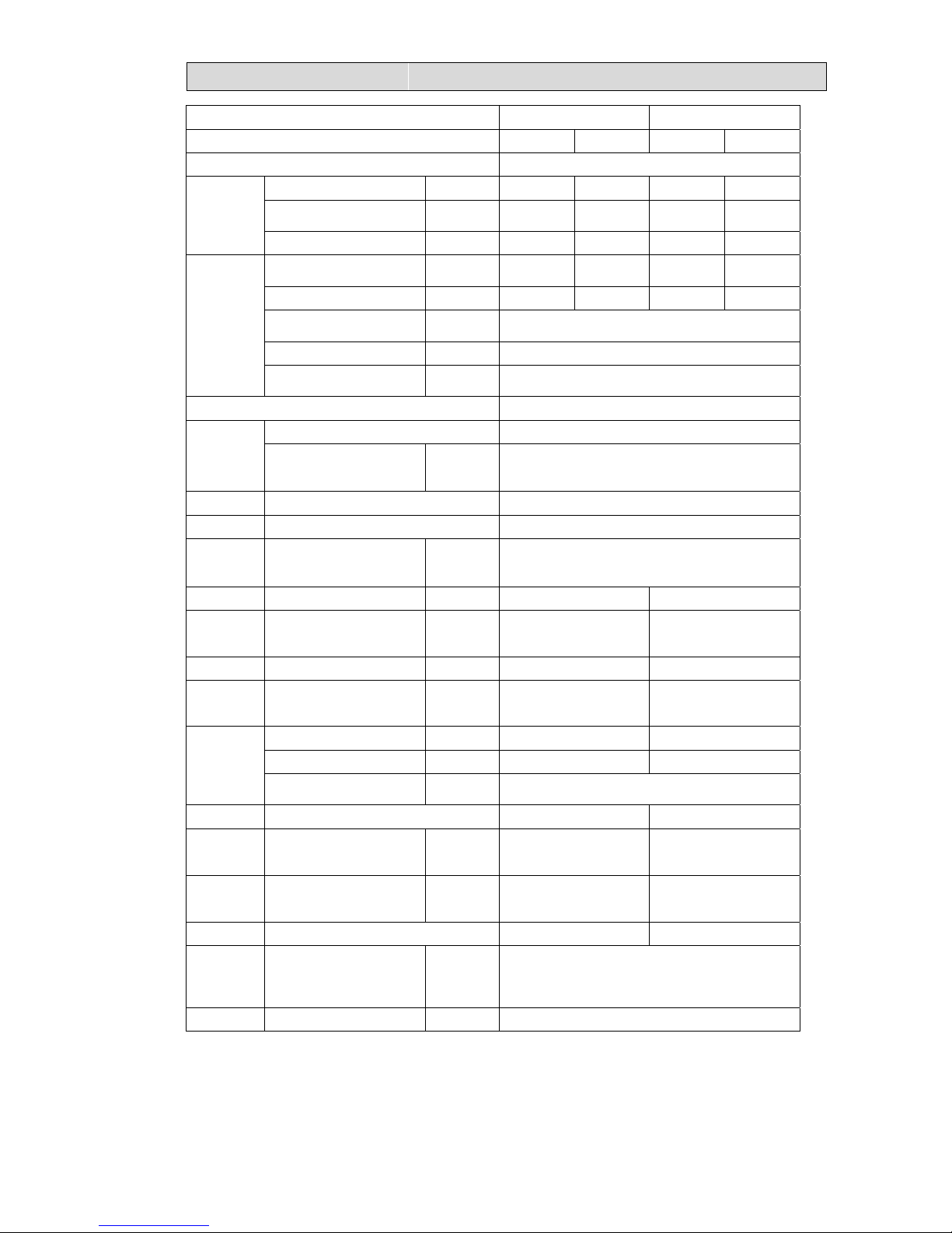
3.12 Mode interfere
For the reason that all indoor units use one outdoor unit, outdoor unit can only run
with same mode(cooling or heating), so, when the mode you set is different from the
mode that outdoor is running with, mode interfere occurs. Following shows the mode
interfere scene.
cooling dry heating fan
cooling √ √ × √ √ --- normal
dry √ √ × √ × --- mode interfere
heating × × √ ×
fan √ √ × √
Outdoor unit always run with the mode of first indoor unit that turned on. when the
setting mode of following indoor unit is interfered with it, 3 beeps would be heard, and
the indoor unit interfered with the normal running units would turn off automatically.
Page 74

66.. CCOONNTTRROOLL MMOODDEEL
L
69
6-2 Outdoor mode control
Summarization
This direction applies to multi-type and DC variable frequency air conditioner
Performance index
1. Voltage scale: 176V~264V,50Hz
2. Storage temperature scale: -40℃~85℃
3. Storage humidity scale: PH30%~PH95%
4. Working temperature:-20℃~85℃
5. accuracy for temperature control: ±0.5℃
3.Control function
Cooling Anti-freeze Protection
To prevent freezing caused by too low temperature of indoor evaporator, the air
conditioner will implement real-time detection over the indoor coil temperature. If the indoor
coil temperature is too low, the compressor will be prohibited from increasing the frequency or
decrease the frequency even shut down automatically
Heating Overload Protection
To prevent system overload caused by excessive pressure in heating operation, the
machine will implement real-time detection over the indoor fan-coil temperature:
If the indoor coil temperature grows higher, the compressor will be prohibited from
increasing the frequency; If the temperature continues to rise, the compressor will decrease
the frequency; If the indoor coil temperature is too high, the compressor will stop working
immediately. The compressor then will reboot after the indoor coil temperature reduces.
Cooling Overload Protection
To prevent system overload due to excessive pressure during cooling operation, the
machine will implement real-time detection over the outdoor condenser coil temperature:
If the outdoor coil temperature grows higher, the compressor will be prohibited from
increasing the frequency; If the temperature continues to rise, the compressor will decrease
Page 75

66.. CCOONNTTRROOLL MMOODDEEL
L
70
the frequency; If the outdoor fan-coil temperature is too high, then the compressor will stop
working immediately. The compressor will reboot after the outdoor coil temperature reduces.
Discharge Temperature Protection
To prevent working conditions of compressor from deteriorating due to high discharge
temperature, the machine will implement real-time detection over the discharge
temperature.
If the discharge temperature grows higher, the compressor will be prohibited from
increasing the frequency; if the temperature continues to rise, the compressor will decrease the
frequency automatically; if the discharge temperature is too high, the compressor will stop
working immediately. The compressor will then reboot when the discharge temperature
returns to normal condition.
Oil-return Control
When the compressor continues to operate at low frequency, there will be an oil return.
The compressor increases the frequency, and thus to return the oil in refrigerate system to
the compressor.
Operation Mode
1 Mode Categories
Air conditioning mode is the operation mode set by users through remote controller,
four modes are available: cooling, heating, dehumidification, as well as fan mode.
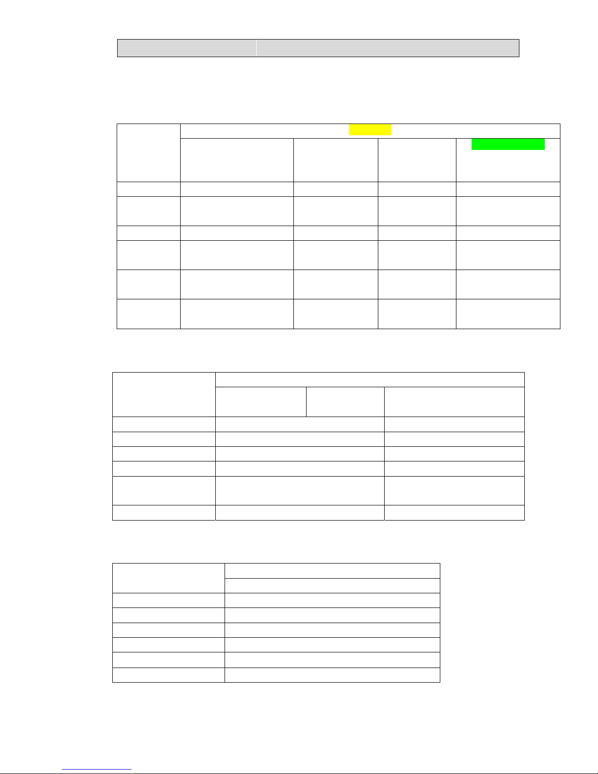
2 Mode conflict
The operating mode of outdoor unit is decided by the operating mode of the indoor unit
firstly booted. Indoor unit subsequently booted will firstly determine whether it’s own mode is
conflict with the outdoor mode. If so, the indoor unit will automatically shut down after three
beeps; If there is no conflict, the indoor unit will boot normally. The relationship of mode
conflict is as follows:
Driven
choice
Active mode
Cooling Dehumidifica
tion
Heati
ng
fan
Cooling √ √ × √
Dehumidific
ation
√ √ × √
Heating × × √ ×
fan √ √ × √
Page 76

66.. CCOONNTTRROOLL MMOODDEEL
L
71
√―――Mode conflict will not happen
×―――Mode conflict will happen
Outdoor four-way Valve Control
Four-way valve of the outdoor machine shuts down when cooling but starts when
heating. The operation of heating defrosting refers to defrosting operation and, when the
heating remote shutdown, the four-way valve disconnects in 50s when the compressor
stops working.
Start-up Protection:
To prevent compressor from restart frequently in the condition that system pressure has
not been completely balanced, it can’t be restarted within 3 minutes.
Pressure Protection:
Pressure switch is normally kept open. When the pressure grows too high, the pressure
switch will close and soft will enter pressure protection control. soft will automatically
decrease the frequency. If the pressure is still unable to return to normal condition after
decreasing frequency, compressor will stop and report the fault code of pressure protection.
Page 77

77.. TTRROOUUBBLLEE SSHHOOOOTTIINNGG
72
7-1- Error code
When the air conditioner failure occurs, the fault code will displays on outdoor control
board , wire remote controller or display panel.
1. INDOOR UNINT FAULT CODE DISPLAY
WALL MOUNTED TYPE
Run the air-conditioner by wireless remote controller , continue pressing
the“SLEEP ”button for 4 times, fault codes will flashing rapidly on the LCD . If no fault ,"00"
will display.
“ER”shows indoor display panel Communication fault with indoor unit control board .
FLOOR STANDING TYPE
In the case of no button-locked,continue pressing “CLOCK”button for 8 times ,fault
codes will display on the LCD for 10 seconds,automatically disappears after 10seconds.
Continue pressing “SLEEP”button of wireless remote controller for 8 times ,fault codes
will display on the LCD for 10 seconds,automatically disappears after 10seconds.
Check indoor unit control board---FAILURE LAMP
LED3 and LED2 indicates fault codes: LED2 indicate ten fault code, LED3 indicate bits
fault code (as shown fig. below).
“ER”shows indoor display panel Communication fault with indoor unit control board
LED2 and LED3 are failure indicate
lamps,
LED2 indicate fault code ten digit
number, LED3 indicate single digit
number code
Page 78

77.. TTRROOUUBBLLEE SSHHOOOOTTIINNGG
73
DUCT TYPE AND CASSETTE TYPE
(1) ERROR CODES INDICATED BY WIRE REMOTE CONTROLLER(see fig. below)
FIG.2 ERROR CODE DISPLAY ON WIRE REMOT CONTROLLER
(2)WITH DISPLAY PANEL(CASSETTE type and CEILING &FLOOR type)
Lamp RUN(LED2 ,red) and Lamp DEFROST(LED5 ,green)flashing,Lamp RUN display
fault code ten digit number, lamp DEFROST display fault code single digit number (as
shown fig. below).
For example,fault code 36: led RUN & defrost flash 3 times at the same time, and led
DEFROST continue flash 3 times, reports No. 36 fault.
When failure occurs, this lamp light ON.
This number shows ERROR CODE.
When display“FE” ,shows that the wire controller
can’t receive the signals of indoor unit control
board ,please check communication wires.
Page 79

77.. TTRROOUUBBLLEE SSHHOOOOTTIINNGG
74
Page 80

77.. TTRROOUUBBLLEE SSHHOOOOTTIINNGG
75
LED FALSH CONTROL:flash 300mS(T1),off 300mS(T2),after 2000mS(T3)fault code
repeat displays. (as shown below)
T1 T2 T3
Fig.2 LED FALSH CONTROL
3.Duct type indoor units of VRF---FAULT CODE DISPLAY BY INDOOR BOARD
LED2 and LED5 are failure indicate
lamps,
LED2(RED) indicate fault code ten
digit number, LED5(GREEN)
indicate single digit number code
Page 81

77.. TTRROOUUBBLLEE SSHHOOOOTTIINNGG
76
2.OUTDOOR UNINT FAULT CODE DISPLAY
(1) ON/OFF UNITARY TYPE(equipped with outdoor control box)
Fault code display by indicate lamps of outdoor control board.
LED FALSH CONTROL:flash 300mS(T1),off 300mS(T2),after 900mS(T3)fault
code repeat displays. (as shown below)
T1 T2 T3
( 2 ) INVERTER UNITARY AIR CONDITONER , MULTI-SPLIT TYPE AIR
CONDITONER&VRF:
Fault code will display on digital indication board.
VRF:
Indoor unit can indicate both indoor failure and outdoor failure ,but outdoor only
indicate outdoor’s.
LED2-fault code lamp
Page 82

77.. TTRROOUUBBLLEE SSHHOOOOTTIINNGG
77
3.Fault code display ( Driver Board )
Fault code display by indicate lamps of outdoordriver board.
LED FALSH CONTROL:flash 200mS(T1),off 200mS(T2),after 900mS(T3)fault
code repeat displays. (as shown below)
T1 T2 T3
Page 83

77.. TTRROOUUBBLLEE SSHHOOOOTTIINNGG
78
The following is the fault code table of outdoor.
Fault
code
Fault description Fault description REMARKS
1
Outdoor environment temperature
sensor fault
Outdoor environment
temperature sensor
short circuit or open
circuit
2
The outdoor coil sensor fault
The outdoor coil
temperature sensor short
circuit or open circuit
3
Current protective device
4
EEprom Data error
EEprom Data error or EE
chip fault
5
Refrigeration and freezing or thermal
overload protection
Refrigeration indoor coil
temperature is too low or
heating the indoor coil
temperature too high
6
AC motor fault
7
Indoor and outdoor communication fault
Outdoor continuously for 2
minutes without receipt of
indoor communication data
8
Phase current imbalance
Application of three-phase
power supply models
9
Current U phase
Application of three-phase
power supply models
10
Current V phase
Application of three-phase
power supply models
11
Sequence error
Three phase power supply
wiring line sequence error
Application of
three-phase power
supply models
12
Phase detection phase
Application of
three-phase power
supply models
13
Compressor overheat protection device
Compressor overheating
protector tripping
14
High voltage switch motor
protection/Pressure shutdown protection
Too high system pressure
leads to high pressure
switch tripping or pressure
sensors to detect the
pressure too high to
achieve shutdown
Were applied to have high
pressure switch or a
pressure sensor type
Page 84

77.. TTRROOUUBBLLEE SSHHOOOOTTIINNGG
79
Fault
code
Fault description Fault description REMARKS
protection pressure
15
Low voltage switch protection/Low pressure
protection shutdown
System low pressure
causing low pressure
switch tripping or pressure
sensors to detect the
pressure is too low to
achieve the shutdown
protection pressure
Were applied to the low
pressure switch or a
pressure sensor type
16
Refrigeration overload protection
The outdoor coil
temperature is too high to
reach refrigeration
temperature shutdown
protection
17
Exhaust temperature sensor fault
Exhaust temperature
sensor short circuit or open
circuit
18
AC voltage of high and low voltage protection
/ fault
Power input AC voltage is
too low or too high
MUTI-SPLIT TYPE
ONLY
19
Intake air temperature sensor fault
Exhaust temperature
sensor short circuit or open
circuit
20
Condenser entrance temperature sensor
fault
Condenser entrance
temperature sensor short
circuit or open circuit
21
The outlet of the condenser temperature
sensor fault
The outlet of the condenser
temperature sensor short
circuit or open circuit
22
The defrosting sensor fault
The outlet of the condenser
temperature sensor short
circuit or open circuit
23
Expansion valve A tube sensor fault
Expansion valve A tube
sensor short circuit or open
circuit
FOR
MUTI-SPLIT&inverter
unitary types
24
Expansion valve B tube sensor fault
Expansion valve B tube
sensor short circuit or open
circuit
FOR MUTI-SPLIT
outdoor
25
Expansion valve C tube sensor fault
Expansion valve C tube
sensor short circuit or open
circuit
FOR MUTI-SPLIT
outdoor
Page 85

77.. TTRROOUUBBLLEE SSHHOOOOTTIINNGG
80
Fault
code
Fault description Fault description REMARKS
26
Expansion valve D tube sensor fault
Expansion valve D tube
sensor short circuit or open
circuit
FOR MUTI-SPLIT
outdoor
27
Expansion valve A thick pipe sensor fault
Expansion valve A thick
pipe sensor short circuit or
open circuit
FOR MUTI-SPLIT
&inverter unitary
types
28
Expansion valve B thick pipe sensor fault
Expansion valve B thick
pipe sensor short circuit or
open circuit
FOR MUTI-SPLIT
outdoor
29
Expansion valve C thick pipe sensor fault
Expansion valve C thick
pipe sensor short circuit or
open circuit
FOR MUTI-SPLIT
outdoor
30
Expansion valve D thick pipe sensor fault
Expansion valve D thick
pipe sensor short circuit or
open circuit
FOR MUTI-SPLIT
outdoor
31
High discharge pressure fault
VRF outdoor
32
Low suction pressure fault VRF outdoor
41
Current sensor fault
Application of
three-phase power
supply ON/OFF
TYPES
42
Voltage sensor fault
43
H Pressure sensor fault
VRF
44
L Pressure sensor fault
45
IPM fault
46
IPM Communication fault
47
Too high exhaust temperature shutdown
48
Outdoor DC fan fault
49
Outdoor DC fan fault
90
Forced expansion valve
91
IPM Temperature rise too high downtime
92
Compression ratio is too large to stop VRF TYPES
93
The machine number and set the
number of inconsistencies fault
VRF
94
outdoor address conflict
VRF
Page 86

77.. TTRROOUUBBLLEE SSHHOOOOTTIINNGG
81
Fault
code
Fault description Fault description REMARKS
95
Refrigerant serious excessive downtime
VRF
96
Refrigerant shortage downtime
VRF
97
Four way valve fault
FOR VRF&inverter
unitary types
Page 87

77.. TTRROOUUBBLLEE SSHHOOOOTTIINNGG
82
The following is the fault code table of indoor.
FAULT
CODE
FAULT DISCRIPTION REMARKS
31 Panel key ADfault Only for MUTI-SPLIT
32
The front panel fault is not in place
Only for MUTI-SPLIT
(two upper and lower position detecting switch and also put
in place
or not in place)
33 Room Temperature Sensor Fault Only for MUTI-SPLIT
34 Coil Temperature Sensor Fault Only for MUTI-SPLIT
35
Panel drive
fault
Only for MUTI-SPLIT
(two upper and lower panel position detection s witch is
not
in accordance with thereservation timing action)
36 Communication between Indoor and Outdoor Fault Only for MUTI-SPLIT
37 humidity sensor failure Only for MUTI-SPLIT
38 EEprom Data error Only for MUTI-SPLIT
39 Indoor Fan Motor Fault Only for MUTI-SPLIT
40 Grid protection Only for MUTI-SPLIT
51 Drainage Fault
52 Grid protection
53
The front panel fault is not in place
(two upper and lower position detecting switch and also put
in place
or not in place)
55 Conflict Model Fault
ONLY FOR MUTI-SPLIT &
VRF TYPES
56 Freeze Protection
57 Overload Protection
61 Indoor address duplication For VRF
62 Remote address duplication For VRF
64 Communication between Indoor & Outdoor unit Fault
65
Communication between Indoor &Wiring remote controller
Fault
For VRF
71 The indoor zero crossing detection fault
72 Indoor Fan Motor Fault
73 EEPROM Data Error
74
Panel drive
fault
(two upper and lower panel position detection s witch is
not
in accordance with thereservation timing action)
80 Panel key ADfault
81 Ambient Temperature Sensor Fault
82 Evaporator Inlet Temperature Sensor Fault
83 Evaporator Middle TemperatureSensor Fault
84 Evaporator outlet Temperature Sensor Fault
Page 88

77.. TTRROOUUBBLLEE SSHHOOOOTTIINNGG
83
85 Wiring Remote Controller Sensor Fault
86 Outlet temperature sensor fault
87 The water side entrance temperature senso r fault
88 The water side entrance temperature senso r fault
89 Humidity sensor failure
FE
Communication between main control board &Wiring
remote controller Fault(display on wiring remote
controller)
ER
Communication between main control board &display
board Fault(displays on display board)
Page 89

88.. CCHHEECCKKIINNGG CCOOMMPPOONNEENNTTSS
84
8-1. Check refrigerant system
TEST SYSTEM FLOW
Conditions: ① Compressor is running.
② The air condition should be installed in good ventilation.
Tool: Pressure Gauge
Technique: ① see ② feel ③ test
SEE ----- Tube defrost.
FEEL ----- The difference between tube’s temperature.
TEST ----- Test pressure.
cooling run heating run
Lo Hi
Pressure
gauge
Lo Hi
Pressure
gauge
Lo Hi
Pressure
gauge
Lo Hi
Pressure
gauge
Lo Hi
Pressure
gauge
Lo Hi
Pressure
gauge
Page 90

88.. CCHHEECCKKIINNGG CCOOMMPPOONNEENNTTSS
85
Test system flow
Cooling mode
Test system
pressure.Does the low
pressure normal at
service part ?
The pressure on the
high side.
The pressure on the
low side.
Recharge refrigerant
after air purging with
the vacuum
pump.Does the low
pressure nomal over
again?
Air remaining at the
refrigerant system.
yes
The system wants
refrigerant.The service
people must be ration
refrigerant(about 100g/
per)in the cooling
mode fixed
frequency.Is the low
pressure rise ?
NO
Recharge refrigerant .
yes
The refrigerant system
blocked.Please check
the Capillary Tube( or
electronic expansion
valve)Is it blocked?
Unsolder the capillary tube
ASS'Y(or electronic expansion
valve).The capillary tube1 is blown
by N
2
.
Check check valve and 4way valve.
If the pressure is
close to static
pressure?
NO
NO
4-way valve collude or
compressor exhaust very
ebb.
yes
NO
yes
Heating mode
Test system
pressure.Does the
high pressure normal
at service part ?
The pressure on the
high side.
The pressure on the
low side.
Recharge refrigerant
after air purging with
the vacuum
pump.Does the high
pressure normal over
again?
Air remaining at the
refrigerant system.
yes
The system wants
refrigerant.The service
people must be ration
refrigerant(about 100g/
per)in cooling mode fixed
frequency state .Is the
high pressure rise in
heating mode?
NO
Recharge refrigerant
yes
If the pressure is close
to static pressure?
4-way valve collude or
compressor exhaust every
ebb.
yes
Check heat exchanger and
4-way valve.
NO
The capillary tube
blocked.Unsolder the
capillary tube ASS'Y.The
capillary tube1 and capillary
tube2 is blown by N
2
.
NO
Remove the back
panel."see"the
capillary tube1 and
capillary tube2.Is it
defrosting?
yes
NO
Page 91

88.. CCHHEECCKKIINNGG CCOOMMPPOONNEENNTTSS
86
8-2.Check parts unit
1. INDOOR FAN MOTOR
MOTOR EXAMINE AND REPAIR
Circuit diagram:
AMS-07/09/12UR4SN(VG4/VT4/VL4/VQ4/UP4/UL4/UQ4/NS4/ZC4/ZA4/NT4/NK4/NM4/VM4)
1)YYW16-4-532:
BLACK
WHITE
M
A
Vcc
GND
Vout
BROWN
BLACK
YELLOW
WINDIN G
""
""
M The ma i n wind in g
A The auxiliary winding
Capaci t or
Hot protector 100
℃
AMS-18UR4SV(VG4/VL4/VT4/UP4/UL4/UQ4/VQ4/NT4/NK4/NM4)
2)RPG25A-6
AMD-09/12UX4SJD
3)
YSK95-25-4HS10
M:329Ω A1:36.5Ω A2:31Ω A3:30.5Ω A4:34.2Ω A5:91Ω
Page 92

88.. CCHHEECCKKIINNGG CCOOMMPPOONNEENNTTSS
87
AMD-18UX4SJD
4)YSK95-40-4HS11
M:138Ω A1:42.5Ω A2:22Ω A3:17.6Ω A4:14.6Ω A5:81.4Ω
AMC-12/18UX4SAA
5)YDK95-28-4-B
M:240Ω A1:60Ω A2:33Ω A3:143Ω
Page 93

88.. CCHHEECCKKIINNGG CCOOMMPPOONNEENNTTSS
88
AMV-12UR4SA,AMV-18UR4SA
6) YSK1 10-22-4-A(HS24)
M: 187Ω A1:37.5Ω A2:27.8Ω A3:146Ω
Test in resistance.
TOOL: Multimeter.
Test the resistance of the main winding. The indoor fan motor is fault if the resistance of
main winding 0(short circuit)or∞(open circuit).
Test in voltage
TOOL: Multimeter.
Insert screwdriver into to rotate indoor fan motor slowly for 1 revolution or over, and measure
voltage “YELLOW” and “GND” on motor. The voltage repeat 0V DC and 5V DC.
Notes:
1) Please don’t hold motor by lead wires.
2) Please don’t plug IN/OUT the motor connecter while power ON.
3) Please don’t drop hurl or dump motor against hard material. Malfunction may not be observed at
early stage after such shock. But it may be found later, this type of mishandling void our
warranty.
Page 94

88.. CCHHEECCKKIINNGG CCOOMMPPOONNEENNTTSS
89
2. OUTDOOR FAN MOTOR
MOTOR EXAMINE AND REPAIR
Circuit diagram
AMW4-28U4SKC、AMW3-24U4SKC、AMD-24U4SZD
1) YDK70-6H-3:
BROWN
WHITE
A
M
WINDIN G
""
""
MThemainwinding
A The a uxiliary win ding
Capacitor
Hot pr o t ector 13 0
℃
YELLOW
RED
BLACK
BLUE
Winding resistance ( at 20℃)
M: 78Ω A: 80Ω
AMW2-20U4SNC1 AMW3-20U4SZD
2) YDK55-6I-8:
Hot Protector 130℃
Capacitor
"A"-The Auxiliary Winding
"M"-The Main Winding
TP
Winding
C
PINK
YELLOW
PURPLE
WHITE
BROWN
A3A2A1
M
Winding resistance ( at 20℃)
M: 185Ω A: 200Ω
AMW2-16U4SGC1
3) YDK29-6I-22:
Hot Protector 130℃
Capacitor
"A"-The Auxiliary Winding
"M"-The Main Winding
TP
Winding
C
PINK
YELLOW
PURPLE
WHITE
BROWN
A3A2A1
M
Winding resistance ( at 20℃)
M: 283.5Ω A: 180Ω
AMW4-36U4SAC
Page 95

88.. CCHHEECCKKIINNGG CCOOMMPPOONNEENNTTSS
90
4) YDK95-6-9043
P
M1 M2 M3
A
BROWN
YELLOW
WHITE BLACK BLUE RED
WINDING
M: Main winding
A: Auxiliary winding
Capacitor
P
Hot protector
Winding resistance ( at 20℃)
M1:59.1Ω M2:20.3Ω M3:15.3Ω A: 85.8Ω
Test in resistance.
TOOL: Multimeter.
Test the resistance of the main winding. The outdoor fan motor is fault if the resistance of
main winding 0(short circuit)or∞(open circuit).
Notes:
1) Please don’t hold motor by lead wires.
2) Please don’t plug IN/OUT the motor connecter while power ON.
3) Please don’t drop hurl or dump motor against hard material. Malfunction may not be observed at
early stage after such shock. But it may be found later, this type of mishandling void our
warranty.
3. COMPRESSOR
COMPRESSOR EXAMINE AND REPAIR
DC
INVERTER
CONTROLLER
&
RU
()
SV
()
TW
()
POWER
Test in resistance.
TOOL: Multimeter.
Test the resistance of the winding. The compressor is fault if the resistance of winding
0(short circuit)or∞(open circuit)
Familiar error:
1)Compressor motor lock.
2)Discharge pressure value approaches static pressure value .
3)Compressor motor winding abnormality.
Notes:
1)Don’t put a compressor on its side or turn over.
2) Please assembly the compressor in your air conditioner rapidly after removing the plugs.
Don’t place the comp. In air for along time.
Page 96

88.. CCHHEECCKKIINNGG CCOOMMPPOONNEENNTTSS
91
3)Avoiding compressor running in reverse caused by connecting electrical wire incorrectly.
4)Warning! In case AC voltage is impressed to compressor, the compressor performance will
below because of its rotor magnetic force decreasing.
4. INDUCTANCE
Familiar error:
1)Sound abnormality
2)Insulation resistance disqualification.
5. STEP MOTOR
5
4
2
1
Test in resistance.
TOOL: Multimeter.
Test the resistance of winding. The stepper motor is fault if the resistance of winding 0(short
circuit)or∞(open circuit).
6. FUSE
Checking continuity of fuse on PCB ASS’Y.
1) Remove the PCB ASS’Y from the electrical component box. Then pull out the fuse from the
PCB ASS’Y (Fig.1)
Fuse
PCB Ass'Y
Fig.1
2) Check for continuity by a multimeter as shown in Fig.2.
Fuse
Fig.2
7.CAPACITOR
1) Remove the lead wires from the capacitor terminals, and then place a probe on the
Page 97

88.. CCHHEECCKKIINNGG CCOOMMPPOONNEENNTTSS
92
capacitor terminals as shown in Fig.3.
2) Observe the deflection of the pointer, setting the resistance measuring range of the
multimeter to the maximum value.
* The capacitor is “good” if the pointer bounces to a great extent and then gradually returns to
its original position.
* The range of deflection and deflection time differ according to the capacity of the capacitor.
Compressor motor
capacitor
Fan motor
capacitor
Multimeter
Fig.3
Page 98

99.. AAPPPPEENNDDIIXX
101
Forindoorunit
ASSeriesWallMountedType
AS‐09/12UR4SVETD5(TG5/TC5/TE5/TF5)
AS‐18UR4SFATD5(TD5/TG5/TC5)
Servicemanualseparatelyattached.
Page 99

AS-09UR4SVETD5(TG5/TC5)
AS-12UR4SVETD5(TG5/TC5)
AS-18UR4SFATD5(TG5/TC5)
AS-24UR4SDBTD5(TG5 /TC5)
Hisense Corporation
Page 100

Type of contents
1. OPERATION RANGE
2. INSTALLATION
3. REFRIGERANT FLOW DIAGRAM
4. ELECTRICAL DATA
5. CONTROL MODE
6. TROUBLE SHOOTING
7. CHECKING COMPONENTS
NOTE: The figure、size and parameter of the product may not be identical
with the service manual, please take the actual product as the standard.
 Loading...