

Page 1

WiFi Instruction
IMPORTANT:
For successful operation, please
read these requirements carefully
before operation and store them
in a safe place for later reference.
ENG LISH
Engli sh
Page 2
Contents
1 WiFi Module Specifiction
2 Smart Phone Requirements
3 Percautions
4 Techn ical So lutio n
5 How to install WiFi Module
6 How to register an account
7 How to pair with device
8 How to delete device
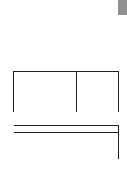
1 WiFi Module Specifiction
WiFi Module Model No. AEH-W4F1
Transmission frequ ency
Transmission power
Power supply
Operating temperature -1
Operating humidity 20%~8 5%RH
2412MHz-2462MHz
≤16.66 dBm
5V / 400mA
0°C~70°C
2 Smart Phone Requirements
Termina l device Andro id
System
requi rements
Resol ution
Andro id 4.4 or
later versions
800*4 80 and
above
— 1 —
IOS 8 or later
versi ons
960*6 40 and
above
IOS
Engli sh
ENG LISH
Page 3

3 Percautions
Smart phone installed with Applicatio n.
Not all of Android and IOS system are compati ble
with APP. We will not be responsible f or any is sue
as a result of the incompatibility.
A 2.4GHz wireless router which connects i ntern et.
For wireless router, WPA-PSK/WPA2-PSK encryption
is recommended.
Due to dynamic network connectivity re quest m ay
time out.In this event,re-run t he netw ork.
Due to dynamic network connectivity co ntrol p roces ses
may time out, App and product may display con flict ing
setting information.Recon nect to s ync inf ormat ion.
Note: All technical information speci fied in t his ins truction
shall b e subject to actual performance ,and th e final
expla nation right should be reserved by compa ny.
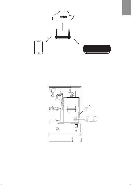
4 Technical solution
Smart system contains:
1)Smart phone
2)Smart Air conditioner
3)Clo ud server
4)2.4Ghz Wireless router
— 2 —
Engli sh
ENG LISH
Page 4
Technic al Solution
5 How to install WiFi module
For air conditioner
Rem ove scr ew
1)O pen air c ondit ioner p anel, a nd use to ols to di smant le the te rmina l cover ;
— 3 —
Engli sh
ENG LISH
Page 5
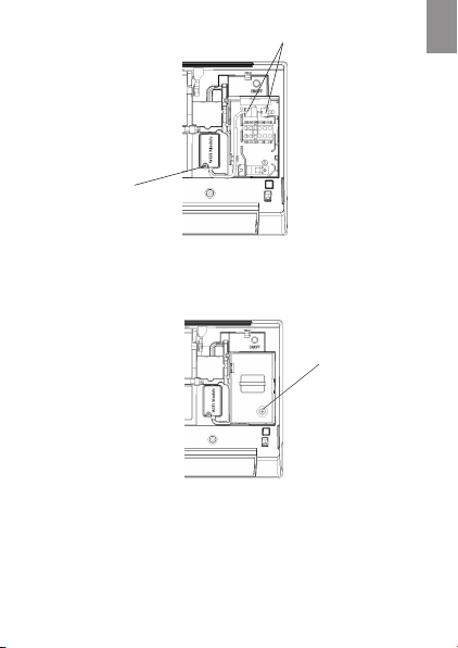
Con nect wi re term inals
Tigh ten WiF i
mod ule by sc rew
2)Fix WiFi module with tools, and c onnec t the wir e
terminals of the module and of the in terna l machi ne
Fix t ermin al cove r
3)Fix the terminal cover with too ls, and t hen WiF i
module installation is finished.
Note:Please refer to actual pro duct fo r speci fic
installation method. This instruction is only
serve d as reference.
— 4 —
Engli sh
ENG LISH
Page 6

6 How to register an account
After installing the application,e nter th e appli cation by
click ing the desktop Icon. Select "Joi n now", i nput th e
information in the list and then cl ick the " Join no w".
The system will send a registrati on code t o the use r’s
regis tered e-mailbox, the user then su bmits t he code
and activates the account. Then the user can sign in
the applicaiton.
7 How to pair with device
Before pairing your device, please mak e sure yo ur
smartphone is connected to the In terne t throu gh a
wirel ess router. The smartphone and the
appli ance can’t be paired through cell ular da ta
servi ce.
For a Dehumidifier: press "mode" and "fa n"
button at the same time and the buzze r will so und
3 times, wait until the display sho ws "P2" ;
For a Portable AC: click "SWING" but ton 6 tim es
on the remote and the buzzer will sou nd 5 time s ,
wait until the display shows "77";
For Air conditioner, press Horizon Airflo w butto n
6 times on the remote and the buzzer wi ll soun d 5
times, wait until the display sho ws "77" .
— 5 —
Engli sh
ENG LISH
Page 7

For Android system
Engli sh
1 In “Home”,click the
lower right corner “+”
— 6 —
Dev ice set up
Ste p 1 of 3:
Sel ect the d evice y ou
wis h to conn ect
Hi- Smart- XXXX
2 selec t the device you wish
to connect, then select
“Next”
Gui de
Scan ing
Nex t
Page 8

De vi ce s etu p
Step 2 o f 3:
Sele ct your n etwor k
Myh ome
Lov efami ly
3 Selec t your wireless
network in your house,
then select “Next”
Sc an in g
Nex t
— 7 —
De vi ce s etu p
Ste p 3 of 3:
Ente r your ne twork p asswo rd
Pas sword
Add t he new de vice
4Input the network
passw ord,then click
“Add the new device”,
waiting for pairing to
compl ete
Engli sh
ENG LISH
Page 9

For IOS system
Engli sh
Dev ice set up
Ste p 1 of 3:
Sele ct the de vice yo u wish to
Ch oose D evi ce
1 Selec t “Choose Device”,
appli cation will jump to
“Settings”
Gui deBac k
Nex t
— 8 —
Settings
Air p lane Mo de
WLA N
Blu tooth
Cel lular
Not ifica tions
Con trol Ce nter
Do No t Distu rb
Gen eral
Dis play & Br ightn ess
Lov efami ly
2 Select “WLAN”
Off
Page 10

Engli sh
Set tings
WLA N
CHO OSE A NETWOR K
WLA N
Hi- Smart - XXXX
Lov efami ly
Myh ome
3 Select your device
cap tive. apple .com
Hi- Smart -XXXX
Redirecting to
Wi-Fi setup in app
Please wait
4 Wait to jump to ste p 2, if
a interface of “Open in HiSmart Ai r”,please select
“Open”
— 9 —
Log I n
Page 11

Ba ck
De vi ce s etu p
Step 2 o f 3:
Myh ome
Lov efami ly
3 Select your wireless
network in your house,
then select “Next”
Sc an in g
Nex t
— 10 —
Ba ck
De vi ce s etu p
Ste p 3 of 3:
Ente r your ne twork p asswo rd
pas sword
Con nect And R egist er
4Input the network
passw ord,then click
“Conn ect And Register”,
waiting for pairing to
complete
ENG LISH
Engli sh
Page 12

8 How to delete device
Engli sh
Dev ice nam e
Note: The above pictures may change in
appli cation, please take the picture s in appl icati on
as the standard
To delete a ny device,
Del ete
selec t the device which
needs to be deleted and
slide the selector to the
left side, as shown in the
picture. For android
users , just press the
scree n for 2 seconds on
the selected device to
delete it.
Versio n No.1955919-01
— 11 —
Page 13

— 12 —
AEH-W4F1 WIFI Module Manual
1. General Description
The wireless module complies with IEEE 802.11 b/g/n standard and it can achieve up to a speed of
72.2Mbps with single stream in 802.11n draft 7.0, 54Mbps as specified in IEEE 802.11g, or 11Mbps
for IEEE 802.11b to connect to the wireless LAN.
This compact module is a total solution for a combination of Wi-Fi 802.11b/g/n technologies with
Microcontroller Processor. The module is specifically developed for embedded system devices.
2. Module Hardware Overview
2.1 Block Diagram
The general Hardware architecture is shown below Figure:
2.2 Features
◆ Single-band 2.4GHz IEEE 802.11b/g/n
◆ Combines an ARM-Cortex M3 MCU,WLAN MAC,a 1T1R capable WLAN baseband,and RF in a
single chip.
◆ Lead-Free / RoHS
◆ Single power supply voltage 3.3V.
Page 14

— 13 —
2.3 Interface
◆ Interface
■ 1.25mm pitch connector
◆ Pin definition
1
23
4
Pin number
Pin name
Pin description
1
RS485A+
Communication line positive
2
RS485B-
Communication line negative
3
GND
Ground pad
4
5V
5.0V Power
3. WiFi RF Specification
RF Specification
Feature Description
Feature Description
WLAN Standard
IEEE 802.11b/g/n(HT20), WiFi compliant
Frequency Range
2.412GHz~2.462GHz
Number of Channels
CH1~CH11 for FCC and ICES, Shield 12,13 Channels with
Software.
CH1~CH13 for Europe.
Modulation
802.11b: CCK, DQPSK, DBPSK
802.11 g/n(HT20): OFDM /64-QAM,16-QAM, QPSK, BPSK
Output Power
≤17dBm
Data Rate
802.11b: 1, 2, 5.5, 11Mbps
802.11g: 6, 9, 12, 18, 24, 36, 48, 54Mbps
802.11n(HT20): 6.5, 13, 19.5, 26, 39, 52, 58.5, 65Mbps
Antenna Reference
Internal Printed ANT: Small antennas with 1.0 dBi peak gain
Page 15

— 14 —
4. Mechanical Specifications
PCB Assembly Dimension:
◆ Dimension (L x W) : L:40.0mm*W:20.0mm
Page 16

— 15 —
5. Requirement of FCC KDB 996369 D03 for module
certification:
5.1 List of applicable FCC rules and Canada rules:
The module complies with FCC Part 15.247, and Canada RSS-247.
5.2 Summarize the specific operational use conditions:
The module has been certified for Fix/Mobile applications. The host product operating
conditions must be such that there is a minimum separation distance of 20 cm (or possibly
greater than 20 cm) between the antenna radiating structures and nearby persons. The host
manufacturer is obligated to confirm the use conditions of the host product to ensure that
distance specified in the instructions is met. In this case the host product is classified as
either a mobile device or a fixed device for RF exposure purposes. This transmitter must not
be co-located or operating in conjunction with any other antenna or transmitter.
5.3 Limited module procedures:
Not applicable.
5.4 Trace antenna designs:
Not applicable.
5.5 RF exposure considerations:
This equipment complies with FCC’s and IC’s RF radiation exposure limits set forth for an
uncontrolled environment. The antenna(s) used for this transmitter must be installed and
operated to provide a separation distance of at least 20 cm from all persons and must not
be collocated or operating in conjunction with any other antenna or transmitter. Installers
must ensure that 20cm separation distance will be maintained between the device and
users.
DÉCLARATION D’IC SUR L’EXPOSITION AUX RADIATIONS:
Cet appareil est conforme aux limites d’exposition au rayonnement RF stipulées par la FCC et l’IC pour
une utilisation dans un environnement non contrôlé. Les antennes utilisées pour cet émetteur
doivent être installées et doivent fonctionner à au moins 20 cm de distance des utilisateurs et ne
doivent pas être placées près d’autres antennes ou émetteurs ou fonctionner avec ceux-ci. Les
installateurs doivent s’assurer qu’une distance de 20 cm sépare l’appareil des utilisateurs.
Note: the OEM product manuals must include a statement in order to alert the users of FCC RF exposure
compliance.
Page 17

— 16 —
5.6 Antennas:
Type
Gain
Impedance
Application
Min Separation
PCB type
Antenna
1.0 dBi
50Ω
Fixed
20 cm.
The antenna is permanently attached, can’t be replaced.
5.7 Label and compliance information:
This device complies with part 15 of the FCC rules. Operation is subject to the
following two conditions:
(1) this device may not cause harmful interference, and (2) this device must accept any interference
received, including interference that may cause undesired operation.
NOTE: The manufacturer is not responsible for any radio or TV interference caused by unauthorized
modifications or changes to this equipment. Such modifications or changes could void the user’s
authority to operate the equipment.
Warning: Changes or modifications to this unit not expressly approved by the party responsible for
compliance could void the user’s authority to operate the equipment.
NOTE: This equipment has been tested and found to comply with the limits for a Class B digital device,
pursuant to part 15 of the FCC Rules. These limits are designed to provide reasonable protection against
harmful interference in a residential installation. This equipment generates uses and can radiate
radio frequency energy and, if not installed and used in accordance with the instructions, may cause
harmful interference to radio communications. However, there is no guarantee that interference will
not occur in a particular installation. If this equipment does cause harmful interference to radio or
television reception, which can be determined by turning the equipment off and on, the user is
encouraged to try to correct the interference by one or more of the following measures:
- Reorient or relocate the receiving antenna.
- Increase the separation between the equipment and receiver.
‐Connect the equipment into an outlet on a circuit different from that to which the receiver is
connected.
‐Consult the dealer or an experienced radio/TV technician for help.
ISED statements:
This device contains licence-exempt transmitter(s)/receiver(s) that comply with Innovation, Science
and Economic Development Canada’s licence-exempt RSS(s). Operation is subject
to the following two conditions:
(1) This device may not cause interference.
(2) This device must accept any interference, including interference that may cause
undesired operation of the device.
L’émetteur/récepteur exempt de licence contenu dans le présent appareil est conforme aux CNRd’
Innovation, Sciences et Développement économique Canada applicables aux appareils radio exempts
de licence. L’ exploitation est autorisée aux deux conditions suivantes :
1) L’ appareil ne doit pas produire de brouillage;
Page 18

— 17 —
2) L’ appareil doit accepter tout brouillage radioélectrique subi, même si le brouillage est
susceptibled’en compromettre le fonctionnement.
The system integrator must place an exterior label on the outside of the final product housing the
AEH-W4F1 Modules. Below is the contents that must be included on this label.
OEM Labeling Requirements:
NOTICE: The OEM must make sure that FCC labeling requirements are met. This includes a clearly
visible exterior label on the outside of the final product housing that displays the contents shown in
below:
Model: AEH-W4F1
Contains FCC ID: 2AGCCAEH-W4F1
Contains IC: 20778-AEHW4F1
5.8 Information on test modes and additional testing requirements:
When testing host product, the host manufacture should follow FCC KDB Publication 996369 D04
Module Integration Guide for testing the host products. The host manufacturer may operate their
product during the measurements. In setting up the configurations, if the pairing and call box options
for testing does not work, then the host product manufacturer should coordinate with the module
manufacturer for access to test mode software. For wireless LAN, the product under test is set into a
link/association with a partnering WLAN device, as per the normal intended use of the product. To ease
testing, the product under test is set to transmit at a high duty cycle, such as by sending a file or
streaming some media content. Alternatively, a Wi-Fi test set may be used. Simultaneously transmitting
modules installed in the host should be all active.
5.9 Additional testing, Part 15 Subpart B disclaimer:
The modular transmitter is only FCC authorized for the specific rule parts (FCC Part 15.247) list on the
grant, and that the host product manufacturer is responsible for compliance to any other FCC rules that
apply to the host not covered by the modular transmitter grant of certification. The final host product
still requires Part 15 Subpart B compliance testing with the modular transmitter installed when contains
digital circuity.
 Loading...