

Hisense AUD-24UX4SFLL3, ADT-18UX4SFKL3, AUD-36UX4SAHH3, AUD-48UX6SPHH3, AUD-42UX6STHH3 Technical & Service Manual
...Page 1

TECHNICAL & SERVICE MANUAL V1.4
—DC-INVERTER AIR CONDITIONERS
MODEL:
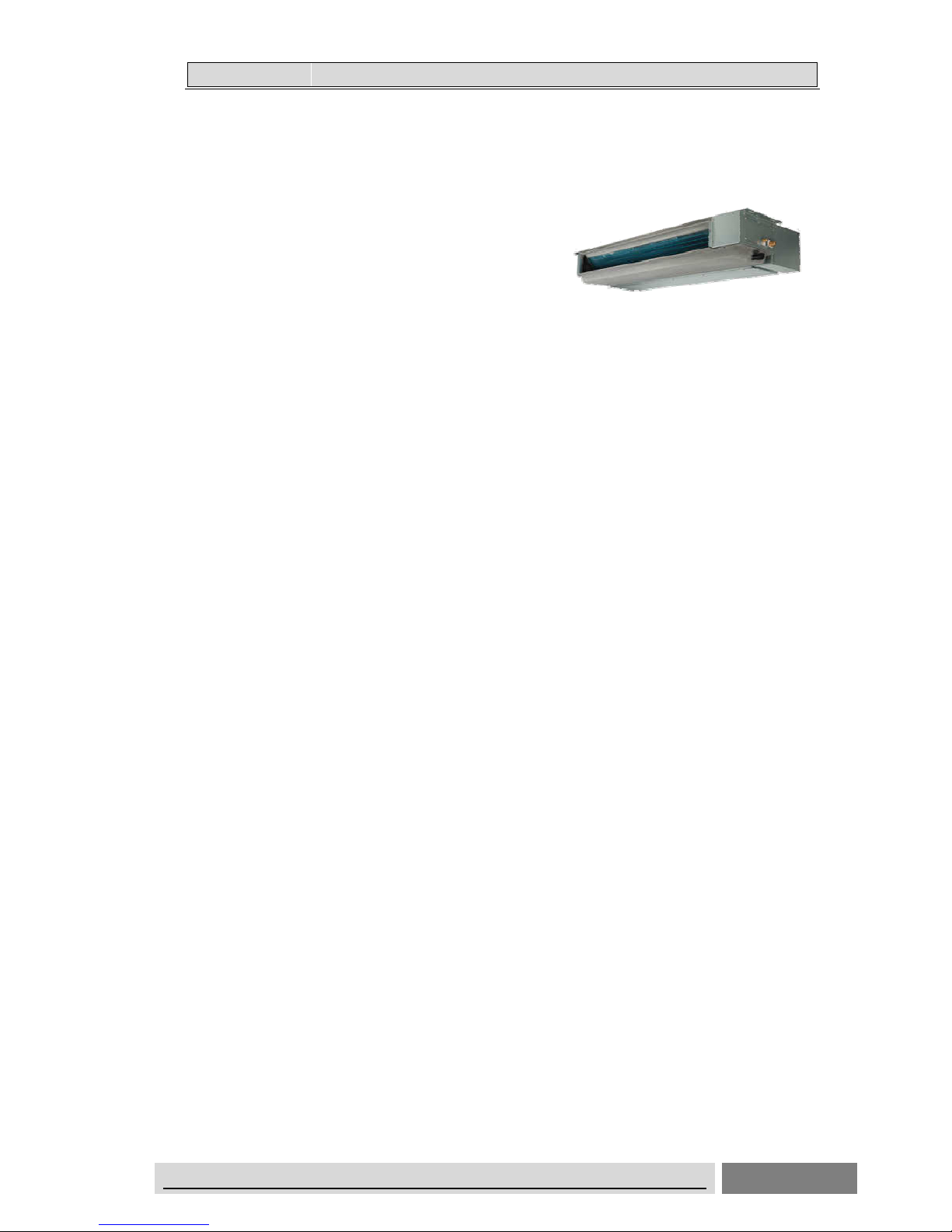
Duct
AUD-09UX4SRNL3
AUD-12UX4SSNL3
AUD-18UX4SFKL3
AUD-24UX4SFLL3
AUD-36UX4SAHH3
AUD-42UX6STHH3
AUD-48UX6SPHH3
AUD-60UX6SPHH3
ADT-09UX4SRNL3
ADT-12UX4SSNL3
ADT-18UX4SFKL3
Cassette
AUC-12UR4SSAA3
AUC-18UR4SFAA3
AUC-24UR4SFGB3
AUC-36UR4SAGB3
AUC-42UR6STHB3
AUC-48UR6SPHB3
AUC-60UR6SPHB3
ACT-12UR4SSAA3
ACT-18UR4SFAA3
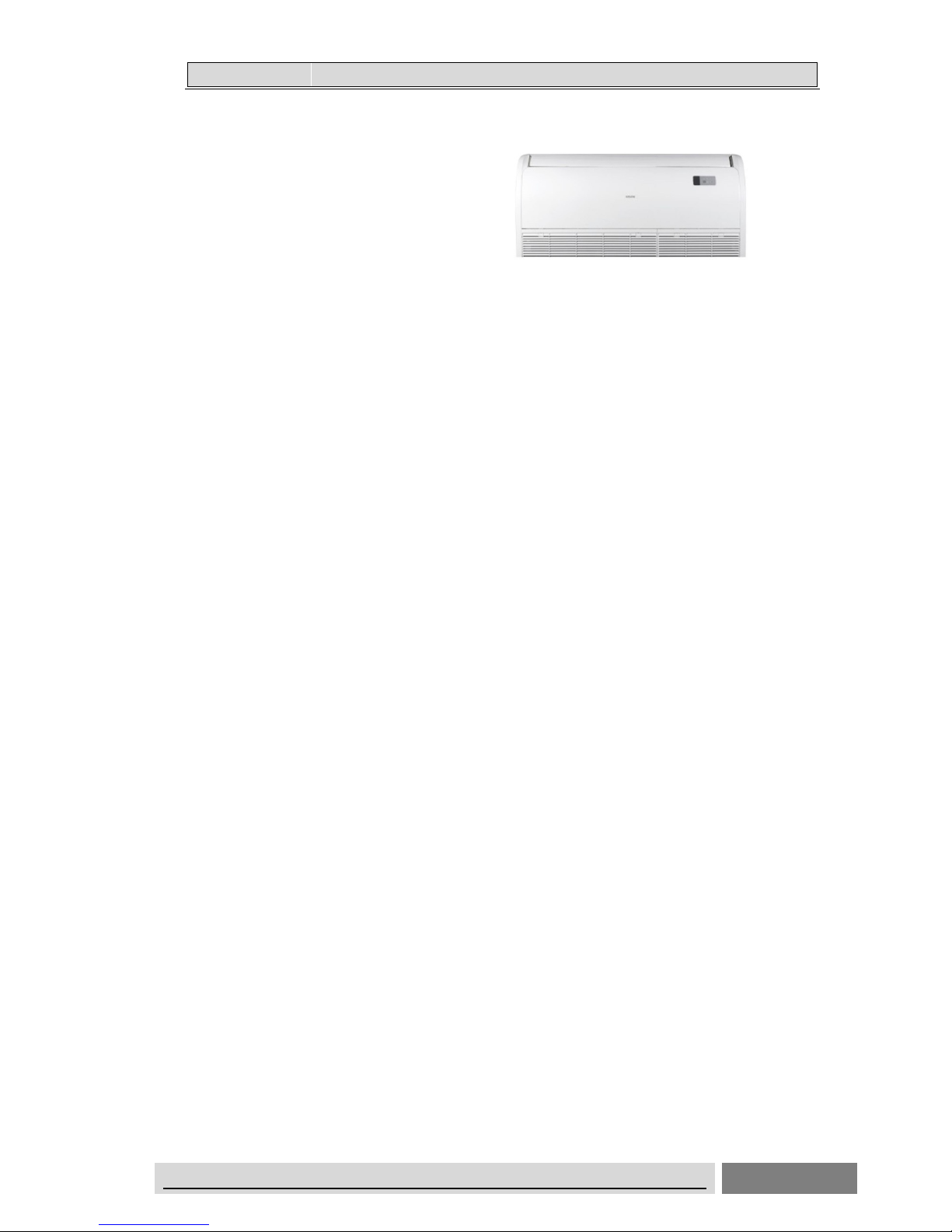
Ceiling & Floor
AUV-18UR4SFA3
AUV-24UR4SFA3
AUV-36UR4SAB3
AUV-42UR6STC3
AUV-48UR6SPC3
AUV-60UR6SPC3
AVT-18UR4SFA3
Page 2

DC-Inverter Air Conditioner Technical & Service Manual
Table of Contents
1. General ............................................................................................................................ 1
1.1 Features ................................................................................................................. 1
1.2 Product lineup ........................................................................................................ 4
1.3 Model identification ................................................................................................. 5
1.4 Unit construction ..................................................................................................... 5
1.5 Working range ........................................................................................................ 6
1.6 Product picture ....................................................................................................... 7
2. Specifications ................................................................................................................ 14
2.1 Duct type .............................................................................................................. 14
2.2 Cassette type ....................................................................................................... 18
2.3 Ceiling&Floor type ................................................................................................ 22
3. Outlines and dimensions ............................................................................................... 26
3.1 Indoor units
............................................................................................................. 26
3.2 Outdoor units
........................................................................................................... 31
4. Electrical data ................................................................................................................ 37
5. Capacities and selection data ........................................................................................ 38
5.1 Capacity characteristic charts
................................................................................... 38
5.2 Piping length correction factor
................................................................................... 53
5.3 Correction factors according to defrosting operation
..................................................... 55
6. Sound pressure data
......................................................................................................... 56
7.
Air flow distribution(Cassette type) ................................................................................ 64
8.
ESP (External static pressure)chart (Duct type) ......................................................... 66
9. Refrigerant cycle ............................................................................................................ 74
10. Fresh air intake function .............................................................................................. 79
11. Wiring diagram ............................................................................................................ 80
11.1 Electrical wiring diagrams
........................................................................................ 80
11.2 Control board picture .......................................................................................... 91
11.3 Field setting ........................................................................................................ 96
11.4 Instructions for the function setting of access control, fire protection, ON/OFF 104
11.5 Common wiring ................................................................................................. 106
11.6 Sensor parameter ............................................................................................. 108
12. Piping work and refrigerant charge ............................................................................ 115
12.1 MAX. length allowed ......................................................................................... 115
12.2 Oil trap .............................................................................................................. 115
12.3 Additional refrigerant charge ............................................................................. 116
13. Control mode ............................................................................................................. 117
13.1 Indoor unit mode control ................................................................................... 117
13.2 Outdoor unit mode control ................................................................................ 120
14.Troubleshooting .......................................................................................................... 121
14.1Trouble guide
........................................................................................................ 121
14.2 Fault codes
.......................................................................................................... 126
15. Checking components ............................................................................................... 136
15.1 Check refrigerant system .................................................................................. 136
15.2 Check parts unit ............................................................................................... 138
Page 3
11..GGEENNEERRAAL
L
DC-INVERTER AIR CONDITIONER TECHNICAL&SERVICE MANUAL
1
1. General
1.1 Features
Duct Type Air Conditioner
Features
Save Installation Space
The indoor unit can be installed inside the ceiling conveniently.
Optional Static Pressure
Optional ESP, a variety of optional installation methods.
High Efficiency and Environment Friendly New Refrigerant-R410A
R410A can protect the environment and do not harm to the ozone layer.
24-hour Timer ON and OFF
This Timer can be set to automatically turn the unit on or off within a 24-hour period.
Mute Operation
The excellent fan design enable the airflow to be quiet and smooth with minimum
noise.
Meeting Various Installation Requirements
The back-air-inlet type is usually to be adopted according to the actual installation
space.The unit is also installed with down-air-inlet type and the noise will increase
about 5-6dB.
Self Recovery of Power Break
When the power supply is recovered after break, all preset are still effective and the
air-conditioner can run according to the original setting.
Fault Self-diagnose Function
When there is something wrong with the air-conditioner
,
the micro computer could
diagnose the faults, which can be read from the display and is convenient for
maintenance.
Page 4

11..GGEENNEERRAAL
L
DC- INVERTER AIR CONDITIONER TECHNICAL&SERVICE MANUAL
2
Cassette Type Air Conditioner
Features
Save Installation Space
The indoor unit can be installed inside the ceiling conveniently.
High Efficiency and Environment Friendly New Refrigerant-R410A
R410A can protect the environment and do not harm to the ozone layer.
24-hour Timer ON and OFF
This Timer can be set to automatically turn the unit on or off within a 24-hour period.
Mute Operation
The excellent fan design enable the airflow to be quiet and smooth with minimum noise.
Self Recovery of Power Break
When the power supply is recovered after break, all preset are still effective and the
air-conditioner can run according to the original setting.
Fault Self-diagnose Function
When there is something wrong with the air-conditioner, the micro computer could diagnose
the faults, which can be read from the display and is convenient for maintenance.
Page 5
11..GGEENNEERRAAL
L
DC-INVERTER AIR CONDITIONER TECHNICAL&SERVICE MANUAL
3
Ceiling &Floor Air Conditioner
Features
Save Installation Space
The indoor unit’s thickness is only 230mm,can be installed inside the ceiling conveniently
.
Flexible
Installation Options
According to the actual installation space,The indoor unit can be installed in the
ceiling
or
on the floor. One unit, Two installation method.
High Efficiency and Environment Friendly
New Refrigerant-R410A
R410A can protect the environment and do not harm to the ozone layer.
24-hour Timer ON and OFF
This Timer can be set to automatically turn the unit on or off within a 24-hour period.
Mute Operation
The excellent fan design enable the airflow to be quiet and smooth with minimum noise.
Various Refrigerant Pipe Connect Methods
The refrigerant pipe can be connect from 3 different directions(rear,right or top) .More
methods, more conveniently.
Self Recovery of Power Break
When the power supply is recovered after break, all preset are still effective and the
air-conditioner can run according to the original setting.
Fault Self-diagnose Function
When there is something wrong with the air-conditioner, the micro computer could diagnose
the faults, which can be read from the display and is convenient for maintenance.
Page 6
11..GGEENNEERRAAL
L
DC-INVERTER AIR CONDITIONER TECHNICAL&SERVICE MANUAL
4
1.2 Product lineup
Type
Model Cooling
Capacity
(×1000Btu/h)
9K 12K 18K 24K 36K 42K 48K 60K
Duct
Type
AUD-
● ● ● ● ● ● ● ●
Cassette
Type
AUC-
● ● ● ● ● ● ●
Ceiling&
Floor type
AUV-
● ● ● ● ● ●
●
---available model
Page 7
11..GGEENNEERRAAL
L
DC-INVERTER AIR CONDITIONER TECHNICAL&SERVICE MANUAL
5
1.3 Model identification
1.4 Unit construction
1:1 system is the only combination compatible.
(1 indoor unit only can be connected with 1 outdoor unit.)
A U D -09 U X 4 S R N L 3
N:Indoor Unit Code
S:Refrigerant R410A F:Refrigerant R22
2:220-230V ~,60Hz, 4:220-240V ~, 50Hz
6:380-415V ~,50Hz
X: Wire Romote Controller R:Wireless Romote Controller
Unit
Air Conditioner
R:Outdoor Unit Code
U:DC-Invert Heat Pump Type , H:Heat Pump Type
C:Cooling Only Type
Type:D-Duct Type,C-Cassette Type,V-Ceiling&Floor Type
H-Floorstanding Type, W-Outdoor Unit
Cooling Capacity:9x10 Btu/h
³
3:Series Number
L:Low ESP H:High ESP
Page 8

11..GGEENNEERRAAL
L
DC-INVERTER AIR CONDITIONER TECHNICAL&SERVICE MANUAL
6
1.5 Working range
Power Supply
Working Voltage
176V ~ 264V(9K~36K),342V ~ 438V(42K~60K)
Voltage Imbalance
Within a 3% deviation from each voltage at the main terminal of
outdoor unit
Starting Voltage Higher than 85% of the Rated Voltage
Operating temperature range
This heat pump air conditioner has been designed for the following outdoor operating temperatures.
Storage condition:
Temperature -20~65℃
Humidity 30%~80%
Type Mode
Outdoor operating temperature range(℃)
maximum minimum
DC-Inverter Split Air Conditioner
(Heat pump type)
Cooling Operation 48 -15
Heating Operation 24 -15
Page 9

11..GGEENNEERRAAL
L
DC-INVERTER AIR CONDITIONER TECHNICAL&SERVICE MANUAL
7
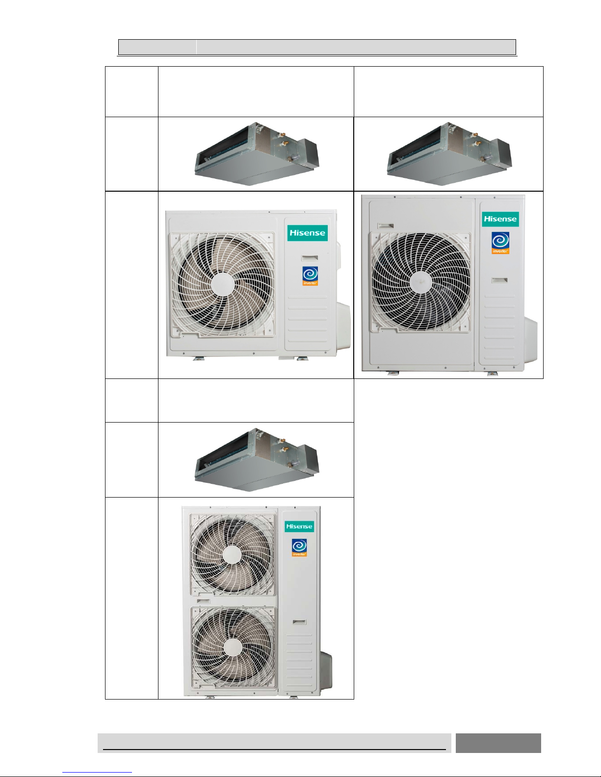
1.6 Product picture
Duct Type
Model
(
Cooling
capacity
)
9K 12K
Indoor
Unit
Outdoor
Unit
Model
(
Cooling
capacity
)
18K 24K
Indoor
Unit
Outdoor
Unit
Page 10
11..GGEENNEERRAAL
L
DC-�INVERTER AIR CONDITIONER TECHNICAL&SERVICE MANUAL
8
Model
(capacity)
36K 42K
Indoor
Unit
Outdoor
Unit
Model
48K/60K
Indoor
Unit
Outdoor
Unit
(capacity)
Page 11
11..GGEENNEERRAAL
L
DC-�INVERTER AIR CONDITIONER TECHNICAL&SERVICE MANUAL
9
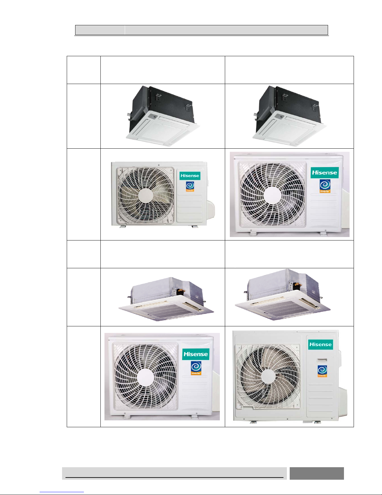
Cassette Type
Model
12K 18K
Indoor
Unit
Outdoor
Unit
Model
24K 36K
Indoor
Unit
Outdoor
Unit
(capacity)
(
capacity)
Page 12

11..GGEENNEERRAAL
L
DC-�INVERTER AIR CONDITIONER TECHNICAL&SERVICE MANUAL
10
Model
42K 48K/60K
Indoor
Unit
Outdoor
Unit
(capacity)
Page 13

11..GGEENNEERRAAL
L
DC-�INVERTER AIR CONDITIONER TECHNICAL&SERVICE MANUAL
11
Ceiling &Floor Type
Model
18K/24K 36K/42K
Indoor
Unit
Outdoor
Unit
Model
48K/60K
Indoor
Unit
Outdoor
Unit
(
capacity)
(capacity)
Page 14

11..GGEENNEERRAAL
L
DC-�INVERTER AIR CONDITIONER TECHNICAL&SERVICE MANUAL
12
Display panel
Cassette Type
5
6
4
6
2
1
1
3
7
5
4
2
3
7
2
1
3
4
5
7
Ceiling & Floor type
Page 15

11..GGEENNEERRAAL
L
DC-INVERTER AIR CONDITIONER TECHNICAL&SERVICE MANUAL
13
The figures in this manual are based on the external view of a standard model.
Consequently, the shape may differ from that of the air conditioner you have selected.
*
It can be set or canceled by professional after-sale staff
Description
1
Run indicator (Red)
It lights on during operation. It lights off during SLEEP mode.
2 Emergency switch
The
filter clean indicator will be off when the switch is pressed. The unit will stop operation
if pressing the button.
When the unit is off,it will start auto operation if pressing the button,if
pressing for more than 5s, the unit will operate in cooling mode.
3 Timer indicator (Green)
It lights on when timer is in use. It lights off when timer finishes.
4 Filter clean (Yellow)
It lights on when the filter should be cleaned.
5 Defrost indicator (Green)
It lights on during defrosting It lights off when defrosting is finished.
6 Buzzer
It beeps when the signal from remote controller is received.
7
Infrared receiver
Receives signal from the remote controller.
Page 16

22.
.
SSPPEECCIIFFIICCAATTIIOONNS
S
14
DC-�INVERTER AIR CONDITIONER TECHNICAL&SERVICE MANUAL
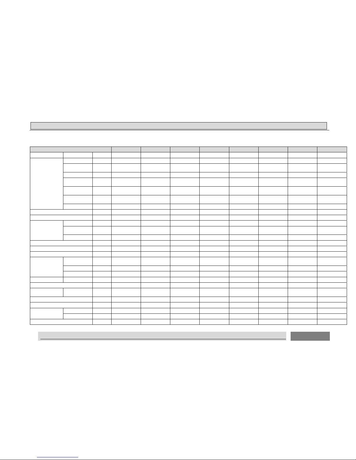
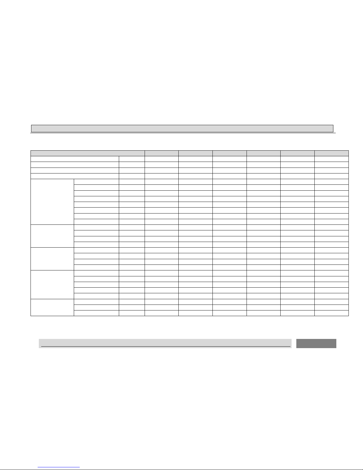
2. Specifications
2.1 Duct type
MODEL 9K 12K 18K 24K 36K 42K 48K 60K
Power supply (Indoor) V-ph-Hz 220~240-1-50 220~240-1-50 220~240-1-50 220~240-1-50 220~240-1-50 220~240-1-50 220~240-1-50 220~240-1-50
Power supply (Outdoor) V-ph-Hz 220~240-1-50 220~240-1-50 220~240-1-50 220~240-1-50 220~240-1-50 380~415-3-50 380~415-3-50 380~415-3-50
Max. input consumption W 1140 1800 2460 4100 5100 6400 7000 7800
Max. input current A 7.8 8.1 11.1 18.1 22.5 11.6 12.0 13.1
Average
Pdesignc
kW 2.7 3.52 5.34 7.05 10.5 11.6 14.0 17.00
SEER W/W 6.15 6.45 6.11 6.23 6.21 6.11 6.11 6.11
Energy Efficiency
Class
A++ A++ A++ A++ A++ A++ A++ A++
Pdesignh kW 2.20 3.52 4.80 6.000 9.000 10.000 12.200 15.000
SCOP W/W 4.01 4.10 4.02 4.08 4.03 4.01 4.02 4.01
Energy Efficiency
Class
A+ A+ A+ A+ A+ A+ A+ A+
Tbiv ℃ -7 -7 -7 -7 -7 -7 -7 -7
Tol ℃ -10 -10 -10 -10 -10 -10 -10 -10
Cooling
Capacity kW 2.70 3.55 5.340 7.05 10.500 12.300 14.000 17.000
Input W 782 1030 1650 2200 3700 4300 4280 5230
Current A 3.6 4.6 7.6 9.7 16.5 7.9 7.8 8.5
EER W/W 3.45 3.55 3.23 3.23 2.84 2.86 3.27 3.25
Heating
Capacity kW 2.740 3.700 6.010 8.05 11.5 14.0 16.0 20.00
Input W 700 945 1720 2370 3400 4100 4240 5360
Current A 3.0 4.2 7.9 10.5 15.2 7.5 7.7 8.7
COP W/W 3.91 3.91 3.49 3.39 3.38 3.41 3.77 3.73
Indoor fan motor
Model
SIC-68CVL-F140-1 SIC-68CVL-F140-
1
YSK110-40-4-A SIC-70CW-F195-1
SIC-101CW-F125
0-4
SIC-101CW-F125
0-4
SIC-101CW-F125
0-4
SIC-101CW-F125
0-4
Qty 1 1 1 1 1 1 1 1
Output W 40 40 40 95 250 250 250 250
Capacitor uF NA NA 2 NA NA NA NA NA
Page 17
22.
.
SSPPEECCIIFFIICCAATTIIOONNS
S
15
DC-�INVERTER AIR CONDITIONER TECHNICAL&SERVICE MANUAL
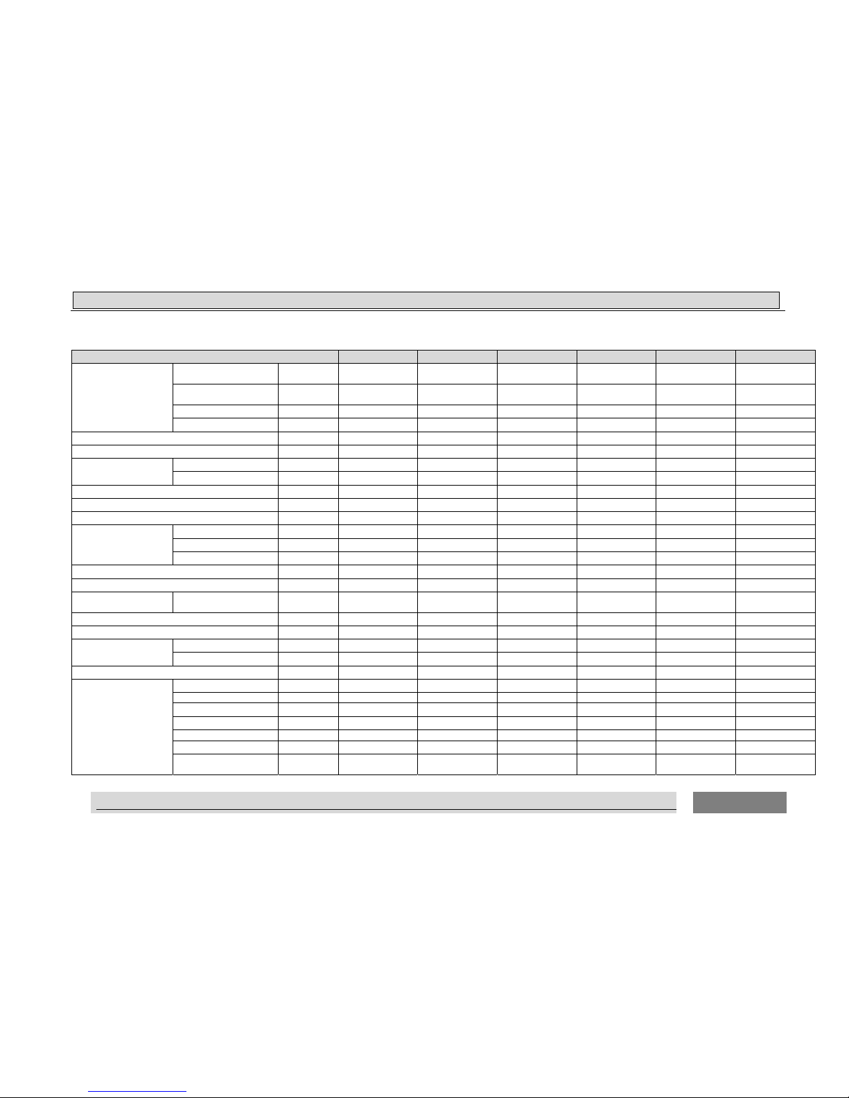
MODEL 9K 12K 18K 24K 36K 42K 48K 60K
Speed(Hi/Med/Lo) r/min 770/640/540 880/740/610 1130/950/850 890/790/690 800/700/600 910/810/710 1100/1000/900 1100/1000/900
Indoor coil
Number of rows 3 3 3 3 3 3 3 3
Tube pitch(a)xrow
pitch(b)
mm 21x13.6 21x13.6 21x13.6 21x13.6 21x18.19 21x18.19 21x18.19 21x18.19
Fin spacing mm 1.6 1.6 1.6 1.6 1.4 1.4 1.5 1. 5
Fin type
Hydrophilic
aluminium
Hydrophilic
aluminium
Hydrophilic
aluminium
Hydrophilic
aluminium
Hydrophilic
aluminium
Hydrophilic
aluminium
Hydrophilic
aluminium
Hydrophilic
aluminium
Tube outside
dia.and type
mm
Φ7,innergroove
tube
Φ7,innergroove
tube
Ф7,innergroove
tube
Ф7,innergroove
tube
Ф7, innergroove
tube
Ф7, innergroove
tube
Ф7.0, innergroove
tube
Ф7.0, innergroove
tube
Coil length x
height x width
mm 768x189x40.8 515x252x40.11 1038x189x40.8 700x294x40.8 1100x378x54.57 1100x378x54.57 1100x378x54.6 1100x378x54.6
Number of circuits 4 4 4 4 9 9 9 9
Indoor air flow Rated(Hi/Med/Lo) m3/h 500/400/320 575/484/400 900/840/730 1100/976/852 1450/1250/1050 1750/1500/1300 2400/2200/1900 2400/2200/1900
Indoor air flow Rated(Hi/Med/Lo) CFM 294/235/188 338/285/235 529/494/429 647/574/501 853/735/618 1029/882/765 1415/1300/1124 1415/1300/1124
ESP
Rated (test) Pa 35 35 35 35 47 60 60 60
Rated (Factory
default)
Pa 0 0 10 25 47 60 60 60
Range Pa 0~50 0~50 10/30 0~80 0~120 0~120 0~120 0~120
Indoor noise level (Hi/Med/Lo) dB(A) 32/28/25 36/34/29 43/41/38 44/41/38 46/42/39 51/47/44 55/52/50 56/53/50
Indoor noise level (sound power) dB(A) 44 49 56 57 62 67 68 70
Throttle type NA NA NA NA NA NA NA NA
Indoor unit
Dimension
(WxHxD)
mm 900x190x447 900x190x447 1170x190x447 900x270x720 1300x350x800 1300x350x800 1300x350x800 1300x350x800
Packing(WxHxD) mm 1070x236x580 1070x236x580 1340x236x580 1170x870x340 1550x410x940 1550x410x940 1550x410x940 1550x410x940
Net/Gross weight kg 19/23.5 19/23.5 24/29 32/37 51/60 51/60 51/60 51/60
Design pressure H/L MPa 4.15/1.6 4.15/1.6 4.15/1.6 4.15/1.6 4.15/1.6 4.15/1.6 4.15/1.6 4.15/1.6
Drainage water pipe diameter mm DΦ32 DΦ32 DΦ32 DΦ32 DΦ32 DΦ32 DΦ32 DΦ32
Refrigerant piping
Liquid side/
Gas side
mm(inch)
Φ6.35/Φ9.52
(1/4'/3/8')
Φ6.35/Φ9.52
(1/4'/3/8')
Φ6.35/Φ12.7
(1/4'/1/2')
Φ9.52/Φ15.88
(3/8'/5/8')
Φ9.52/Φ19.05
(3/8'/3/4')
Φ9.52/Φ19.05
(3/8'/3/4')
Φ9.52/Φ19.05
(3/8'/3/4')
Φ9.52/Φ19.05
(3/8'/3/4')
Controller Wired control Wired control Wired control Wired control Wired control Wired control Wired control Wired control
Operation temperature ℃ 16 - 30 16 - 30 16 - 30 16 - 30 16 - 30 16 - 30 16 - 30 16 - 30
Cooling ℃ 16 - 30 16 - 30 16 - 30 16 - 30 16 - 30 16 - 30 16 - 30 16 - 30
Heating ℃ 16 - 30 16 - 30 16 - 30 16 - 30 16 - 30 16 - 30 16 - 30 16 - 30
Qty’per 20’ /40’ /40'HQ Indoor 200/440/484 200/440/484 160/340/374 84/182/182 35/75/90 35/75/90 35/75/90 35/75/90
Indoor fan motor
Room temperature
Page 18

22.
.
SSPPEECCIIFFIICCAATTIIOONNS
S
16
DC-�IINVER AIR CONDITIONER TECHNICAL&SERVICE MANUAL
MODEL 9K 12K 18K 24K 36K 42K 48K 60K
Compressor
Model ASD088SKNA8JT ASN108D43UFZA ATM150D23UFZ ATF235D43UMT ATF310D43UMT ATF310D43UMT ATH356SDPC9FL LNB42FSAMC
Type ROTARY ROTARY ROTARY ROTARY ROTARY ROTARY ROTARY ROTARY
Brand Highly GMCC GMCC GMCC GMCC GMCC Highly MITSUBISHI
Capacity Btu/h 8549 11123 15427 24361 32380 32380 34470 47699
Input W 575 810 1165 1940 2600 2600 3155 4270
Rated
current(RLA)
A 3 5.7 8 8.9 5.1 5.1 13.2 12.0
Refrigerant oil ml α68HES-H/320
ESTER OIL
VG74/370
ESTEL OIL
VG74/500
POE(VG74)/670 PQE(VG74)/1000 PQE(VG74)/1000
α 68HES-H or
equivalent /1650
FV50S or
PVE/1400
Outdoor fan motor
Model SIC-52FV-F130-3 ZWA138D08A SIC-61FW-F161-1 SIC-61FW-F161-1
SIC-71FW-F8121-1 SIC-81FW-F1138-1 YDK65-6-9061&
YDK65-6-9024
YDK65-6-9061&
YDK65-6-9024
Old Model NA NA NA NA NA NA NA NA
Qty 1 1 1 1 1 1 2 2
Output W 30 30 61 61 121 138 121 121
Capacitor μF NA NA NA NA NA NA NA NA
Speed r/min 820 880 840 880 830 850 810 810
Outdoor coil
Number of rows 1.5 2 2 2 2 2 2 2
Tube pitch(a)x row
pitch(b)
mm 21x18.19 21x18.19 21x21.65 21x18.19 21x21.65 21x21.65 21x21.65 21x21.65
Fin spac ing mm 1.3 1.4 1.4 1.4 1.3 1.6 1.4 1.4
Fin type
Hydrophilic
aluminium
Hydrophilic
aluminium
Hydrophilic
aluminium
Hydrophilic
aluminium
Hydrophilic
aluminium
Hydrophilic
aluminium
Hydrophilic
aluminium
Hydrophilic
aluminium
Tube outside
dia.and type
mm
Φ7,innergroove
tube
Ф7,innergroove
tube
Ф7,innergroove
tube
Ф7,innergroove
tube
Ф7.94,
innergroove tube
Ф7.94,
innergroove tube
Φ7.94,innergroove
tube
Φ7.94,innergroove
tube
Coil length xheight
xwidth
mm 761x504x36.38 840x546x36.38 962x630x43.3 900x630x43.3 970x798x43.5 970x1008x43.5 970x1344x43.3 970x1344x43.3
Number of circuits 4 4 7 4 5 6 12 12
Outdoor noise level
(sound pressure) Hi
dB(A) 52 48 53 53 55 58 53 58
Outdoor noise level (sound power) dB(A) 64 60 65 67 70 73 67 72
Throttle type EEV EEV EEV EEV EEV EEV EEV EEV
Outdoor unit
Dimension
(WxHxD)
mm 730x536x260 810x585x280 860x670x310 860x670x310 950x840x340 950x1050x340 950x1386x340 950x1386x340
Packing(WxHxD) mm 860x600x400 940x640x420 990x730x450 990x730x450 1110x980x460 1110x1200x460 1110x1527x460 1110x1527x460
Page 19

22.
.
SSPPEECCIIFFIICCAATTIIOONNS
S
17
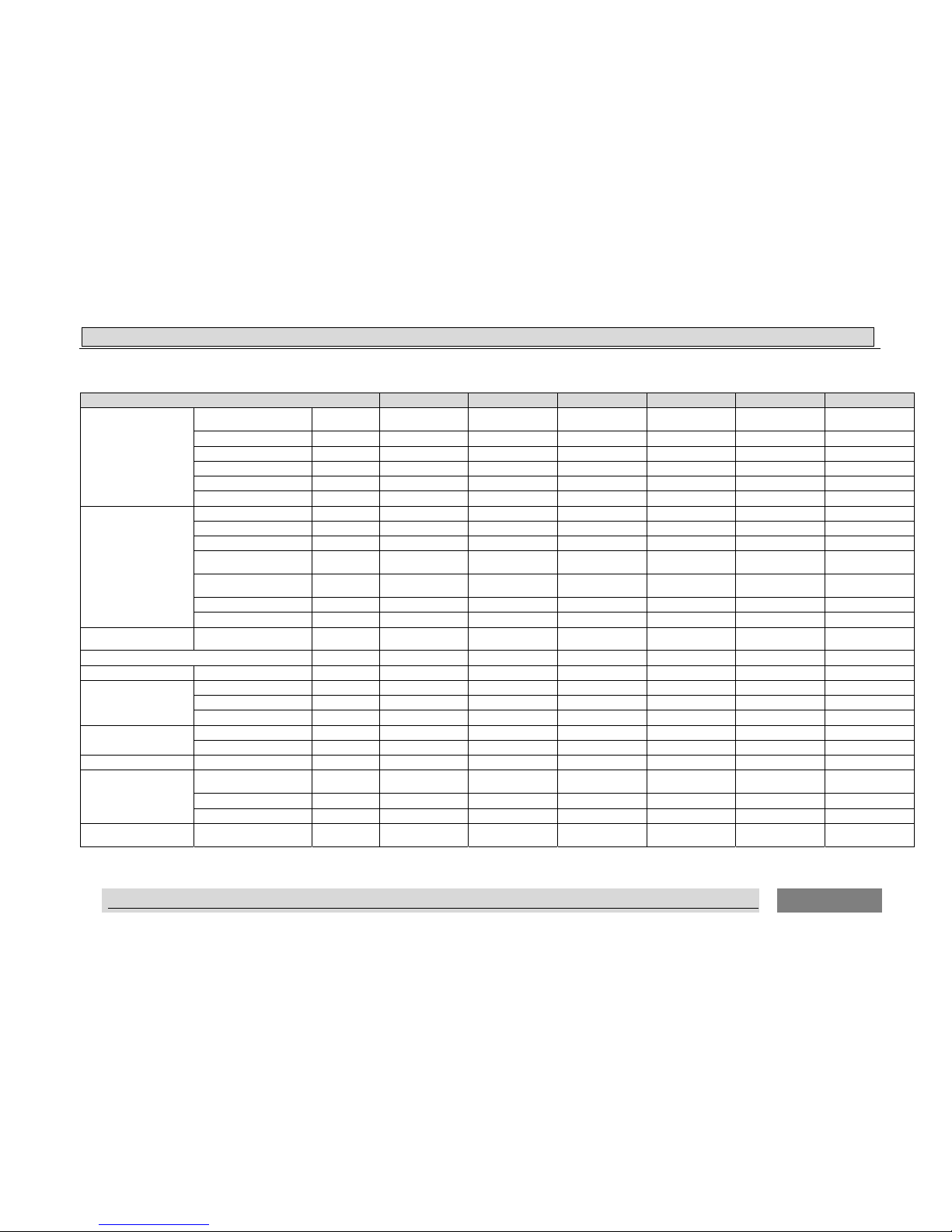
MODEL 9K 12K 18K 24K 36K 42K 48K 60K
Net/Gross weight kg 31/34 34/38.5 45/49 51/57 70/80 85/95 113/125 117/129
Refrigerant
type/Quantity
Type R410a R410a R410a R410a R410 R410 R410A R410A
Charged volume kg 0.83 1.05 1.30 1.70 2.80 3.20 3.78 3.95
Design pressure H/L MPa 4.15/1.60 4.15/1.60 4.15/1.60 4.15/1.60 4.15/1.60 4.15/1.60 4. 15/1.60 4.15/1.60
Refrigerant piping
Liquid side/
Gas side
mm(inch)
Φ6.35/Φ9.52
(1/4'/3/8')
Φ6.35/Φ9.52
(1/4'/3/8')
Φ6.35/Φ12.7
(1/4'/1/2')
Φ9.52/Φ15.88
(3/8'/5/8')
Φ9.52/Φ19.05
(3/8'/3/4')
Φ9.52/Φ19.05
(3/8'/3/4')
Φ9.52/Φ19.05
(3/8'/3/4')
Φ9.52/Φ19.05
(3/8'/3/4')
Max. pipe length m 25 25 30 50 50 50 50 50
Max. difference in
level
m 10 15 15 30 30 30 30 30
Annual energy
consumption(cooling)
kWh/a 154 191 306 396 563 665 802 974
Annual energy
consumption(heating
average)
kWh/a 769 1203 1676 2059 3124 3491 4259 5232
Ambient temperature
Cooling ℃ -15- 48 -15- 48 -15- 48 -15- 48 -15- 48 -15- 48 -15- 48 -15- 48
Heating ℃ -15 - 24 -15 - 24 -15 - 24 -15 - 24 -15 - 24 -15 - 24 -15 - 24 -15 - 24
Qty’per 20’ /40’
/40'HQ
Outdoor
unit
102/213/292 102/204/272 90/186/186 90/186/186 52/106/106 26/53/106 26/53/53 26/53/53
Qty’per 20’ /40’
/40'HQ
Indoor+
Outdoor
80/160/190 66/135/174 55/112/133 40/80/88
22/49/56 20/39/51 19/39/42 19/39/42
NOTE:
1.Test conditions:
Cooling : Indoor: DB27℃/ WB19℃ Outdoor: DB35℃/ WB24℃
Heating: Indoor: DB20℃/ WB15℃ Outdoor: DB7℃/ WB 6℃
2.The Sound Pressure Level is based on the following conditions:
Outdoor unit:
Measure the noise value of 3 points,the points are1 meter in front of the three sides (front/left/right) of the unit surface and height =1/2(unit
height +1) meter from floor level, and calculate the weighted average of the noise.
Indoor unit:
Ducted: Measure the noise value of the point 1.4m below the unit, and 1.0m high from the floor.
The above data was measured in an anechoic chamber. Please take into consideration reflected sound of your specific application environment.
3. The values given in the table for noise level reflect the levels in anechoic chamber.
DC- IINVER AIR CONDITIONER TECHNICAL&SERVICE MANUAL
Page 20
22.
.
SSPPEECCIIFFIICCAATTIIOONNS
S
18
DC-�IINVER AIR CONDITIONER TECHNICAL&SERVICE MANUAL
2.2 Cassette type
MODEL 12K 18K 24K 36K 42K 48K 60K
Power supply (Indoor) V-ph-Hz 220~240-1-50 220~240-1-50 220~240-1-50 220~240-1-50 220~240-1-50 220~240-1-50 220~240-1-50
Power supply (Outdoor) V-ph-Hz 220~240-1-50 220~240-1-50 220~240-1-50 220~240-1-50 380~415-3-50 380~415-3-50 380~415-3-50
Max. input consumption W 1800 2710 4100 5150 6400 6300 7800
Max. input current A 8.1 12.3 18.1 22.5 11.6 11 13.1
Average
Pdesignc kW 3.52 5.30 7.10 10.50 11.20 14.00 17.00
SEER W/W 6.61 6.11 6.45 6.11 6.11 6.11 6.11
Energy Efficiency Class A++ A++ A++ A++ A++ A++ A++
Pdesignh kW 3.520 4.80 6.000 9.000 10.000 12.200 15.300
SCOP W/W 4.25 4.02 4.15 4.08 4.01 4.03 4.01
Energy Efficiency Class A+ A+ A+ A+ A+ A+ A+
Tbiv ℃ -7 -7 -7 -7 -7 -7 -7
Tol ℃ -10 -10 -10 -10 -10 -10 -10
Cooling
Capacity kW 3.650 5.3 7.100 10.5 12.3 14.0 17.0
Input W 1000 1680 2200 3700 4100 4180 5030
Current A 4.4 7.6 9.7 16.5 7.5 7.6 8.3
EER W/W 3.65 3.15 3.23 2.84 3.0 3.35 3.38
Heating
Capacity kW 3.85 6.21 8.20 11.5 14 16 20.0
Input W 970 1900 2370 3600 3900 4230 5320
Current A 4.2 8.3 10.5 16 7.3 7.6 8.6
COP W/W 3.97 3.26 3.46 3.19 3.59 3.78 3.76
Indoor fan motor
Model ARW8901QH
YDK95-28-4-B(HS2
1)
ARW5901QH EHDS50AQH
SIC-72FW-D8124-28 SIC-72FW-D8124-2B SIC-72FW-D8124-2
B
Qty 1 1 1 1 1 1 1
Output W 30 28 35 80 124 124 124
Capacitor uF NA 2 NA NA NA NA NA
Speed(Hi/Med/Lo) r/min 700/590/520 980/840/720 450/390/270 600/480/390 630/600/570 700/540/460 700/540/460
Indoor coil
Number of rows 2 2 2 3 3 3 3
Tube pitch(a)xrow pitch(b) mm 21x13.6 21x13.6 21x13.6 21x13.6 21x13.6 21x13.6 21x13.6
Page 21

22.
.
SSPPEECCIIFFIICCAATTIIOONNS
S
19
DC-�INVERTER AIR CONDITIONER TECHNICAL&SERVICE MANUAL
MODEL 12K 18K 24K 36K 42K 48K 60K
Fin spacing mm 1.5 1.5 1.5 1.5 1.5 1.5 1.5
Fin type
Hydrophilic
aluminium
Hydrophilic
aluminium
Hydrophilic
aluminium
Hydrophilic
aluminium
Hydrophilic
aluminium
Hydrophilic
aluminium
Hydrophilic
aluminium
Tube outside dia.and type mm Ф7,innergroove tube Ф7,innergroove tube Ф7,innergroove tube
Ф7, innergroove
tube
Ф7, innergroove
tube
Ф7.0, innergroove
tube
Ф7.0, innergroove
tube
Coil length x height x width mm 1248x210x27.2 1248x210x27.2
1870×189×27.2
1940x189x40.8 1940x252x40.8 1940x252x40.8 1940x252x40.8
Number of circuits 3 3 4 6 6 6 6
Indoor air flow Rated(Hi/Med/Lo) m3/h 575/484/400 820/730/620 1100/976/852 1600/1300/1000 1850/1700/1550 2000/1900/1700 2000/1900/1700
Indoor air flow Rated(Hi/Med/Lo) CFM 338/285/235 482/429/365 647/574/501 941/765/588 1088/1000/912 1180/1120/1000 1180/1120/1000
ESP
Rated Pa NA NA NA NA NA NA NA
Range Pa NA NA NA NA NA NA NA
Indoor noise level (Hi/Med/Lo) dB(A) 39/37/36 45/41/39 41/38/36 45/40/37 46/43/41 50/48/46 47/45/43
Indoor noise level (sound power) dB(A) 53 58 55 60 61 63 61
Throttle type NA NA NA NA NA NA NA
Indoor unit
Dimension (WxHxD) mm 650x270x570 650x270x570 840x248x840 840x248x840 840x298x×840 840x298x840 840x298x840
Packing(WxHxD) mm 770x310x750 770x310x750 996x370x956 996x370x956 996x420x956 996x420x956 996x420x956
Net/Gross weight kg 19/24 21 /26 25/34 27/36 32/41 32/41 32/41
Panel
Dimension (WxHxD) mm 650x30x650 650x30x650
950×37×950
950x37x950 950x37x950 950x37x950 950x37x950
Packing(WxHxD) mm 730x130x730 730x130x730 990x115x1010 1025x120x1015 1025x120x1015 1025x120x1015 1025x120x1015
Net/Gross weight kg 2.4/ 5 2.4/ 5 6.5/9.5 6.5/9.5 6.5/9.5 6.5/9.5 6.5/9.5
Design pressure H/L MPa 4.15/1.6 4.15/1.6 4.15/1.6 4.15/1.6 4.15/1.6 4.15/1.6 4.15/1.6
Drainage water pipe diameter mm dΦ21 dΦ21 dΦ32 dΦ32 dΦ32 dΦ32 dΦ32
Refrigerant piping Liquid side/ Gas side mm
Φ6.35/Φ9.52
(1/4'/3/8')
Φ6.35/Φ12.7
(1/4'/1/2')
Φ9.52/Φ15.88
(3/8'/5/8')
Φ9.52/Φ19.05
(3/8'/3/4')
Φ9.52/Φ19.05
(3/8'/3/4')
Φ9.52/Φ19.05
(3/8'/3/4')
Φ9.52/Φ19.05
(3/8'/3/4')
Controller Remote control Remote control Remote control Remote control Remote control Remote control Remote control
Operation temperature ℃ 16 - 30 16 - 30 16 - 30 16 - 30 16 - 30 16 - 30 16 - 30
Room temperature
Cooling ℃ 16 - 30 16 - 30 16 - 30 16 - 30 16 - 30 16 - 30 16 - 30
Heating ℃ 16 - 30 16 - 30 16 - 30 16 - 30 16 - 30 16 - 30 16 - 30
Qty’per 20’ /40’
/40'HQ
Indoor 147/315/384 147/315/384 72/144/168 72/144/168 60/120/144 60/120/144 60/120/144
Compressor
Model ASN108D43UFZA ATM150D23UFZ ATF235D43UMT ATF310D43UMT ATF310D43UMT ATH356SDPC9FL LNB42FSAMC
Type ROTARY ROTARY ROTARY ROTARY ROTARY ROTARY ROTARY
Indoor coil
Page 22

22.
.
SSPPEECCIIFFIICCAATTIIOONNS
S
20
DC-�INVERTER AIR CONDITIONER TECHNICAL&SERVICE MANUAL
MODEL 12K 18K 24K 36K 42K 48K 60K
Brand GMCC GMCC GMCC GMCC GMCC Highly MITSUBISHI
Capacity Btu/h 11123 15427 24361 32380 32380 34470 47699
Input W 810 1165 1940 2600 2600 3155 4270
Rated current(RLA) A 5.7 8.1 8.9 5.1 5.1 13.2 12
Refrigerant oil ml
ESTER OIL
VG74/370
ESTEL OIL
VG74/500
POE(VG74)/670 PQE(VG74)/1000 PQE(VG74)/1000
α 68HES-H or
equivalent /1650
FV50S or PVE/1400
Outdoor fan motor
Model ZWA138D08A SIC-61FW-F161-1 SIC-61FW-F161-1 SIC-71FW-F8121-1 SIC-81FW-F1138-1
YDK65-6-9061&
YDK65-6-9024
YDK65-6-9061&
YDK65-6-9024
Old Model NA NA NA NA NA NA NA
Qty 1 1 1 1 1 2 2
Input W 30 61 61 121 138 121 121
Capacitor μF NA NA NA NA NA NA NA
Speed r/min 880 840 880 830 850 810 810
Outdoor coil
Number of rows 2 2 2 2 2 2 2
Tube pitch(a)x row pitch(b) mm 21x18.19 21x21.65 21x18.19 21x21.65 21x21.65 21x21.65 21x21.65
Fin spac ing mm 1.4 1.4 1.4 1.3 1.6 1.4 1.4
Fin type
Hydrophilic
aluminium
Hydrophilic
aluminium
Hydrophilic
aluminium
Hydrophilic
aluminium
Hydrophilic
aluminium
Hydrophilic
aluminium
Hydrophilic
aluminium
Tube outside dia.and type mm Ф7,innergroove tube Ф7,innergroove tube Ф7,innergroove tube
Ф7.94, innergroove
tube
Ф7.94, innergroove
tube
Φ7.94,innergroove
tube
Φ7.94,innergroove
tube
Coil length xheight xwidth mm 840x546x36.38 962x630x43.3 900x630x43.3 970x798x43.5 970x1008x43.5 970x1344x43.3 970x1344x43.3
Number of circuits 2 7 4 5 6 12 12
Outdoor noise level
(sound pressure)
Hi
dB(A) 48 53 53 55 58 53 58
Outdoor noise level (sound power) dB(A) 60 65 67 70 73 67 72
Throttle type EEV EEV EEV EEV EEV EEV EEV
Outdoor unit
Dimension(WxHxD) mm 810x585x280 860x670x310 860x670x310 950x840x340 950x1050x340 950x1386x340 950x1386x340
Packing(WxHxD) mm 940x420x640 990x730x450 990x730x450 1110x980x460 1110x1200x460 1110x1527x460 1110x1527x460
Net/Gross weight kg 34/38.5 45/49 51/57 70/80 85/95 113/125 117/129
Refrigerant
type/Quantity
Type R410a R410a R410a R410 R410 R410A R410A
Charged volume kg 1.05 1.3 1.70 2.80 3.20 3.78 3.95
Design pressure H/L MPa 4.15/1.6 4.15/1.6 4.15/1.6 4.15/1.6 4.15/1.6 4.15/1.6 4.15/1.6
Compressor
Page 23

22.
.
SSPPEECCIIFFIICCAATTIIOONNS
S
21
DC-�INVERTER AIR CONDITIONER TECHNICAL&SERVICE MANUAL
MODEL
Refrigerant piping
Liquid side/ Gas side mm(inch)
12K
Φ6.35/Φ9.52
(1/4'/3/ 8')
18K
Φ6.35/Φ12.7
(1/4'/1/ 2')
24K
Φ9.52/Φ15.88
(3/8'/5 /8')
36K
Φ9.52/Φ19.05
(3/8'/3 /4')
42K
Φ9.52/Φ19.05
(3/8'/3 /4')
48K
Φ9.52/Φ19.05
(3/8'/3 /4')
60K
Φ9.52/Φ19.05
(3/8'/3 /4')
Max. pipe length m 25 30 50 50 50 50 50
Max. difference in level m 15 15 30 30 30 30 30
Annual energy
consumption
(cooling)
kWh/a 186 303 382 601 642 802 974
Annual energy
consumption
(heating average)
kWh/a 1160 1676 2025 3088 3491 4241 5336
Ambient
temperature
Cooling ℃ -15- 48 -15- 48 -15- 48 -15- 48 -15- 48 -15- 48 -15- 48
Heating ℃ -15 - 24 -15 - 24 -15 - 24 -15 - 24 -15 - 24 -15 - 24 -15 - 24
Qty’per 20’ /40’
/40'HQ
Outdoor unit 102/204/272 90/186/186 90/186/186 52/106/106 26/53/106 26/53/53 26/53/53
Qty’per 20’ /40’
/40'HQ
Indoor+
Outdoor
54/112/125 48/102/120 40/82/92 30/60/72 24/52/62 24/47/47 24/47/47
NOTE:
1.Test conditions:
Cooling : Indoor: DB27℃/ WB19℃ Outdoor: DB35℃/ WB24℃
Heating: Indoor: DB20℃/ WB15℃ Outdoor: DB7℃/ WB 6℃
2.The Sound Pressure Level is based on the following conditions:
Outdoor unit:
Measure the noise value of 3 points,the points are1 meter in front of the three sides (front/left/right) of the unit surface and height =1/2(unit
height +1) meter from floor level, and calculate the weighted average of the noise.
Indoor unit:
Cassette: Measure the noise value of the point 1.4m below the unit, and 1.0m high from the floor.
The above data was measured in an anechoic chamber. Please take into consideration reflected sound of your specific application environment.
3. The values given in the table for noise level reflect the levels in anechoic chamber.
Page 24
22.
.
SSPPEECCIIFFIICCAATTIIOONNS
S
22
DC-�INVERTER AIR CONDITIONER TECHNICAL&SERVICE MANUAL
2.3 Ceiling&Floor type
Model
18K 24K 36K 42K 48K 60K
Power supply (Indoor) V-ph-Hz
220~240-1-50 220~240-1-50 220~240-1-50 220~240-1-50 220~240-1-50 220~240-1-50
Power supply (Outdoor) V-ph-Hz
220~240-1-50 220~240-1-50 220~240-1-50 380~415-3-50 380~415-3-50 380~415-3-50
Max. input consumption W 2600 4100 5100 6400 6300 8200
Max. input current A 11 18.1 22.5 11.6 11.0 13.5
Average
Pdesignc kW 5.28 7.0 10.5 11.0 14.0 17.0
SEER W/W 6.80 6.11 6.11 6.11 6.11 6.11
Energy Efficiency Class A++ A++ A++ A++ A++ A++
Pdesignh kW 4.8 6.0 9.0 10.0 12.2 15
SCOP W/W 4.30 4.08 4.11 4.01 4.02 4.01
Energy Efficiency Class A+ A+ A+ A+ A+ A+
Tbiv ℃ -7 -7 -7 -7 -7 -7
Tol ℃ -10 -10 -10 -10 -10 -10
Cooling
Capacity
kW 5.28 7.000 10.5 12.3 14.0 17.0
Input
W 1750 2200 4000 4250 4410 5180
Current
A 7.3 9.7 17.6 7.8 8.1 8.6
EER
W/W 3.02 3.23 2.625 2.89 3.17 3.28
Heating
Capacity
kW 6.0 8.200 11.3 14.0 15.8 20.0
Input
W 1850 2370 3750 4500 4350 5360
Current
A 7.8 10.5 16.3 8.2 8.1 9.2
COP
W/W 3.24 3.46 3.00 3.11 3.63 3.73
Indoor fan motor
Model
SIC-70CW-F1100-6 SIC-70CW-F1100-6 SIC-70CW-F1140-3 SIC-101CW-F1181-2 SIC-101CW-F1181-1 SIC-101CW-F1181-1
Qty 1 1 1 1 1 1
Output W
100 100 140 181 181 181
Capacitor uF
NA NA NA NA NA NA
Speed(Hi/Med/Lo) r/min
800/700/610 1280/1100/920 1220/1160/1080 1200/1100/1000 1250/1000/800 1250/1100/950
Indoor coil
Number of rows
2 3 3 3 3 3.5
Tube pitch(a)xrow pitch(b) mm
21x13.6 21x13.6 21x13.6 21x13.6 21x13.6 21x13.6
Fin spacing mm
1.4 1.5 1.5 1.5 1.5 1.5
Page 25
22.
.
SSPPEECCIIFFIICCAATTIIOONNS
S
23
DC-�INVERTER AIR CONDITIONER TECHNICAL&SERVICE MANUAL
Model
18K 24K 36K 42K 48K 60K
Fin type
Hydrophilic
aluminium
Hydrophilic
aluminium
Hydrophilic
aluminium
Hydrophilic
aluminium
Hydrophilic
aluminium
Hydrophilic
aluminium
Tube outside dia.and type mm
Ф7,innergroove tube Ф7,innergroove tube Ф7, innergroove tube Ф7, innergroove tube
Ф7.0, innergroove
tube
Ф7.0, innergroove
tube
Coil length x height x width mm
691x336x27.2 660x336x40.8 930x336x40.8 1200x336x40.8 1200x336x40.8 1200x336x54.4
Number of circuits
4 3 7 7 7 7
Indoor air flow Rated(Hi/Med/Lo)
m
3
/h
800/690/590 1100/950/800 1700/1500/1300 2000/1800/1600 2000/1600/1200 2000/1700/1500
Indoor air flow Rated(Hi/Med/Lo)
CFM
470/400/340 650/570/500 1000/882/765 1176/1059/941 1180/940/710 1180/1000/880
ESP
Rated
Pa
NA NA NA NA NA NA
Range
Pa
NA NA NA NA NA NA
Indoor noise level (Hi/Med/Lo)
dB(A)
43/39/36 48/46/42 50/49/48 50/48/45 51/45/41 51/46/43
Indoor noise level (sound power)
dB(A)
56 62 63 66 65 65
Throttle type
NA NA NA NA NA NA
Indoor unit
Dimension (WxHxD) mm
990x680x230 990x680x230 1285x680x230 1580x680x230 1580x680x230 1580x680x230
Packing(WxHxD) mm
1100x820x350 1100x820x350 1400x820x350 1690x820x350 1690x820x350 1690x820x350
Net/Gross weight kg
29/34 30/35 37/44 48/56 48/56 50/58
Design pressure MPa
4.15/1.6 4.15/1.6 4.2/1.5 4.2/1.5 4.15/1.6 4.15/1.6
Drainage water pipe diameter mm
DΦ25 DΦ25 DΦ25 DΦ25 DΦ25 DΦ25
Refrigerant piping Liquid side/ Gas side mm
Φ6.35/Φ12.7
(1/4'/1/2')
Φ9.52/Φ15.88
(3/8'/5/8')
Φ9.52/Φ19.05
(3/8'/3/4')
Φ9.52/Φ19.05
(3/8'/3/4')
Φ9.52/Φ19.05
(3/8'/3/4')
Φ9.52/Φ19.05
(3/8'/3/4')
Controller
Remote control Remote control Remote control Remote control Remote control Remote control
Operation temperature ℃
16 - 30 16 - 30 16 - 30 16 - 30 16-30 16-30
Room temperature
Cooling ℃
16 - 30 16 - 30 16 - 30 16 - 30 16-30 16-30
Heating ℃
16 - 30 16 - 30 16 - 30 16 - 30 16-30 16-30
Qty’per 20’ /40’ /40'HQ Indoor 84/168/196 84/168/196 42/84/98 42/84/98 42/84/98 42/84/98
Compressor
Model ATM150D23UFZ ATF235D43UMT ATF310D43UMT ATF310D43UMT ATH356SDPC9FL LNB42FSAMC
Type ROTARY ROTARY ROTARY ROTARY ROTARY ROTARY
Brand GMCC GMCC GMCC GMCC Hitachi MITSUBISHI
Capacity Btu/h 15427 24361 32380 32380 34470 47699
Input W 1165 1940 2600 2600 3155 4270
Rated current(RLA) A 8.1 8.9 5.1 5.1 13.2 12
Refrigerant oil ml
ESTEL OIL
VG74/500
POE(VG74)/670 PQE(VG74)/1000 PQE(VG74)/1000
α 68HES-H or
equivalent /1650
FV50S or PVE/1400
Indoor coil
Page 26
22.
.
SSPPEECCIIFFIICCAATTIIOONNS
S
24
DC-�INVERTER AIR CONDITIONER TECHNICAL&SERVICE MANUAL
Model
18K 24K 36K 42K 48K 60K
Outdoor fan motor
Model SIC-61FW-F161-1 SIC-61FW-F161-1 SIC-71FW-F8121-1 SIC-81FW-F1138-1
YDK65-6-9061&
YDK65-6-9024
YDK65-6-9061&
YDK65-6-9024
Old Model NA NA NA NA NA NA
Qty 1 1 1 1 2 2
Input W 61 61 121 138 121 121
Capacitor μF NA NA NA NA NA NA
Speed r/min 840 880 830 850 810 810
Outdoor coil
Number of rows 2 2 2 2 2 2
Tube pitch(a)x row pitch(b) mm 21x21.65 21x18.19 21x21.65 21x21.65 21x21.65 21x21.65
Fin spacing mm 1.4 1.4 1.3 1.6 1.5 1.4
Fin type
Hydrophilic
aluminium
Hydrophilic
aluminium
Hydrophilic
aluminium
Hydrophilic
aluminium
Hydrophilic
aluminium
Hydrophilic
aluminium
Tube outside dia.and type mm Ф7,innergroove tube Ф7,innergroove tube
Ф7.94, innergroove
tube
Ф7.94, innergroove
tube
Φ7.94,innergroove
tube
Φ7.94,innergroove
tube
Coil length xheight xwidth mm 962x630x43.3 900x630x43.3 970x798x43.5 970x1008x43.5 970x1008x43.5 970x1344x43.3
Number of circuits 7 4 5 6 12 12
Outdoor noise level (sound
pressure) Hi
dB(A) 53 53 55 58 53 58
Outdoor noise level (sound power)
dB(A)
65 67 70 73 67 72
Throttle type EEV EEV EEV EEV EEV EEV
Outdoor unit
Dimension(WxHxD) mm 860x670x310 860x670x310 950x840x340 950x1050x340 950x1386x340 950x1386x340
Packing(WxHxD) mm 990x730x450 990x730x450 1110x980x460 1110x1200x460 1110x1527x460 1110x1527x460
Net/Gross weight kg 45/49 51/57 70/80 85/95 113/125 117/129
Refrigerant type/Quantity
Type R410a R410a R410 R410 R410A R410A
Charged volume kg 1.3 1.70 2.80 3.20 3.78 3.95
Design pressure Hi/Lo MPa 4.15/1.6 4.15/1.6 4.15/1.6 4.15/1.6 4.15/1.6 4.15/1.6
Refrigerant piping
Liquid side/ Gas side mm(inch)
Φ6.35/Φ12.7
(1/4'/1/2')
Φ9.52/Φ15.88
(3/8'/5/8')
Φ9.52/Φ19.05
(3/8'/3/4')
Φ9.52/Φ19.05
(3/8'/3/4')
Φ9.52/Φ19.05
(3/8'/3/4')
Φ9.52/Φ19.05
(3/8'/3/4')
Max. pipe length m 30 50 50 50 50 50
Max. difference in level m 15 30 30 30 30 30
Annual energy
consumption(cooling)
kWh/a 271 404 601 630 802 974
Page 27
22.
.
SSPPEECCIIFFIICCAATTIIOONNS
S
25
DC-�INVERTER AIR CONDITIONER TECHNICAL&SERVICE MANUAL
Model
18K 24K 36K 42K 48K 60K
Annual energy
consumption(heating
average)
kWh/a 1564 2059 3064 3491 4252 5232
Ambient temperature
Cooling ℃ -15- 48 -15- 48 -15- 48 -15- 48 -15- 48 -15- 48
Heating ℃ -15 - 24 -15 - 24 -15 - 24 -15 - 24 -15 - 24 -15 - 24
Qty’per 20’ /40’ /40'HQ Outdoor unit 90/186/186 90/186/186 52/106/106 26/53/106 26/53/53 26/53/53
Qty’per 20’ /40’ /40'HQ
Indoor+Outdoo
r
42/85/98 42/85/98 32/67/72 24/48/60 20/40/53 20/40/53
NOTE:
1.Test conditions:
Cooling : Indoor: DB27℃/ WB19℃ Outdoor: DB35℃/ WB24℃
Heating: Indoor: DB20℃/ WB15℃ Outdoor: DB7℃/ WB 6℃
2.The Sound Pressure Level is based on the following conditions:
Outdoor unit:
Measure the noise value of 3 points,the points are1 meter in front of the three sides (front/left/right) of the unit surface and height =1/2(unit height +1)
meter from floor level, and calculate the weighted average of the noise.
Indoor unit:
Floor Ceiling : Test the noise value of the point 1.4m below the unit,1.0m front the unit and 1.0m high from the floor.
The above data was measured in an anechoic chamber. Please take into consideration reflected sound of your specific application environment.
3.
The values given in the table for noise level reflect the levels in anechoic chamber.
Page 28
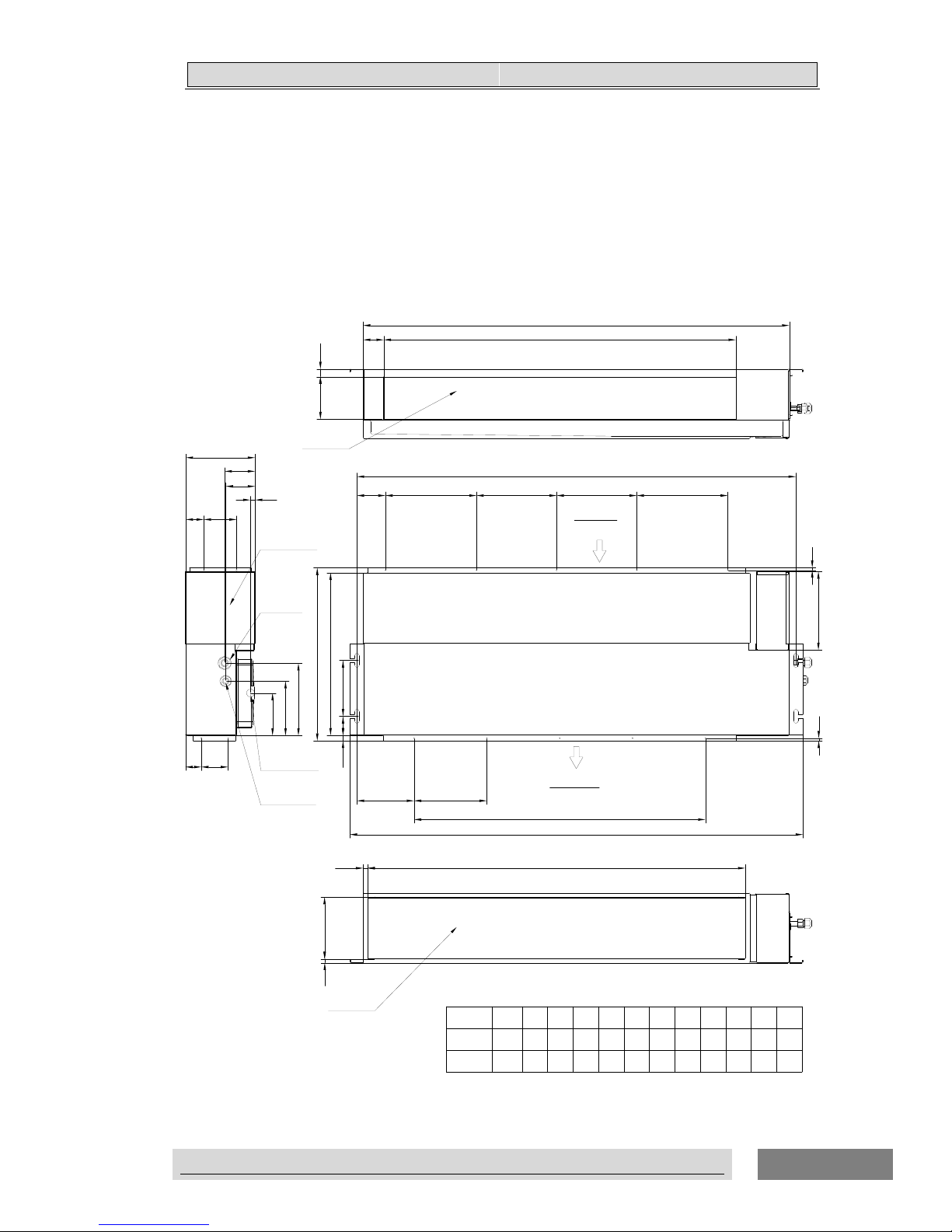
33..OOUUTTLLIINNEESS AANNDD DDIIMMEENNSSIIOONNS
S
DC-�INVERTER AIR CONDITIONER TECHNICAL&SERVICE MANUAL
3. Outlines and dimensions
3.1 Indoor units
Duct type
Unit:mm
abcde fghijk
1246
18K
c
154
447
b
a
117
170
199
117
150
13
81
84
12071170
971
190
216
h
200
i*200=j
d e
78
250
976
9K/12K
937
900 701
73
240
Gas pipe
Drain pipe
Liquid pipe
21
11
56
12
Electric box
f
g
e
220
200
220
0
157
122 3
4
600
800
l
53
k
l
1039
769
476
7
7
15
50 90
44 74
Air outlet
Air inlet
Air inlet
Air outlet
Model
26
Page 29
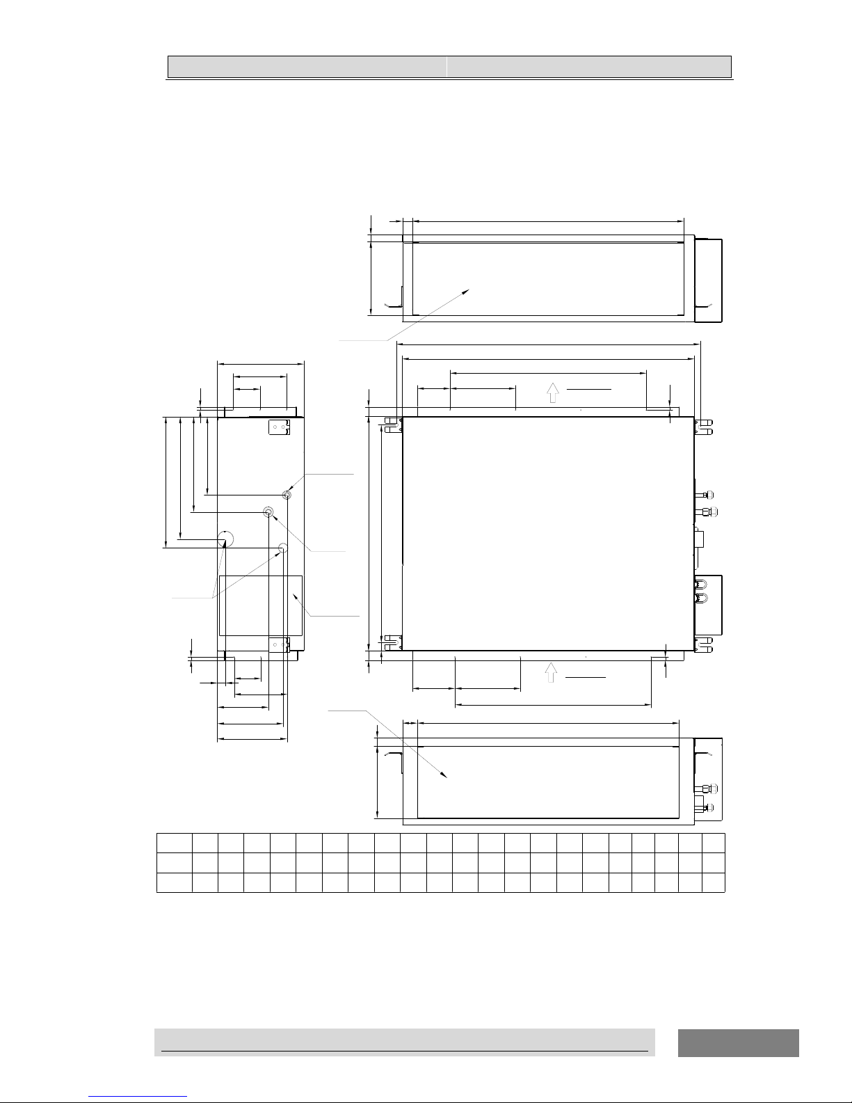
33..OOUUTTLLIINNEESS AANNDD DDIIMMEENNSSIIOONNS
S
DC-�INVERTER AIR CONDITIONER TECHNICAL&SERVICE MANUAL
Unit:mm
a
b
c
d
e
222
f
g
j
h
i
k
25
l
m
n
abcdefghijkl m n op
24K
36K/42K/
48K/60K
934
900
669
720 805
835
228
242
294
378
405
156
202
214
1334
1300 1205
1235
756
800 308
237
312
375
204
242
400
186
q
270
350
Air inlet
Air outlet
Air outlet
Air inlet
Electric box
Gas pipe
Liquid pipe
Drain pipe
300
(
p*300=)q
2
3
900
600
300
(
p*300=)q
r
r
153
s
s
168
30 30
t
2
t
t
u
2
u
u
90 140
82
82
102
117
10
10
10
10
o
25
31
46
24
20
Model
27
Page 30
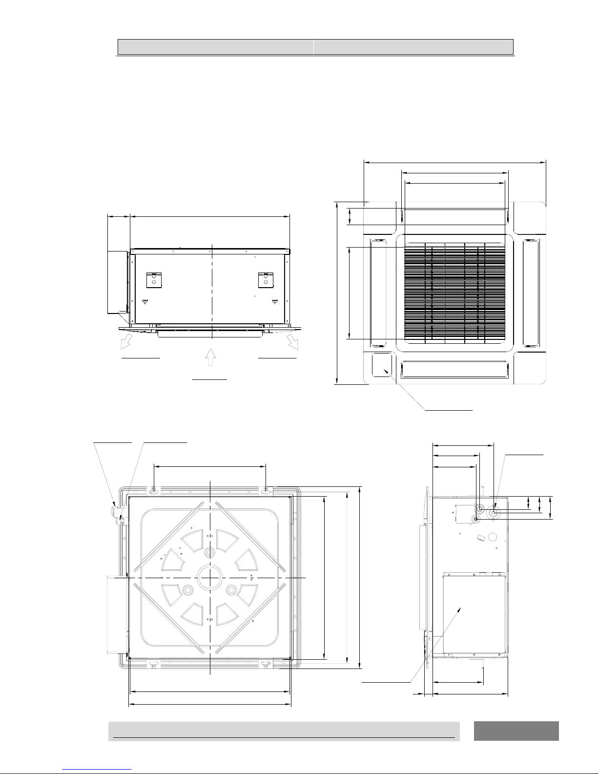
33..OOUUTTLLIINNEESS AANNDD DDIIMMEENNSSIIOONNS
S
DC-�INVERTER AIR CONDITIONER TECHNICAL&SERVICE MANUAL
Cassette Type
12K,18K
Unit:mm
218
168
155
46
58
81
80
270
570
650
650
PANEL
358
382
328
59
Display panel
Drain pipe
Electric box
400
650
570
575~590(Dimension of opening)
Gas pipe
Liquid pipe
575~590(Dimension of opening)
610
181
30
Air inlet
Air outlet
Air outlet
28
Page 31

33..OOUUTTLLIINNEESS AANNDD DDIIMMEENNSSIIOONNS
S
DC-�INVERTER AIR CONDITIONER TECHNICAL&SERVICE MANUAL
24K,36K,42K,48K,60K
Unit:mm
a
24K/36K
42K/48K/60K
248
298
PANEL
Model
29
950
490
102
110
180
127
130
118
102
45 a
950
478
520
841
840
Gas pipe
Liquid pipe
760
Display panel
Drain pipe
Electric box
760
860~910(Dimension of opening)
860~910(Dimension of opening)
Page 32

33..OOUUTTLLIINNEESS AANNDD DDIIMMEENNSSIIOONNS
S
DC-�INVERTER AIR CONDITIONER TECHNICAL&SERVICE MANUAL
Ceiling&Floor Type
Unit:mm
184
a
680
250
170
c 39
230
66 88
43
100
22
180
90
47
100
177
16
90
39
10
ab c
18K/24K
36K
42K/48K/60K
990
912
1285
1207
1580 1502
b
855
1150
1445
16
Air inlet
Air outlet
Air outlet
Electric box
Liquid pipe
Gas pipe
Drain pipe
Air inlet
Display panel
257 241
43
184
44
91
50
50
63
52
50
50
Model
30
Page 33

33..OOUUTTLLIINNEESS AANNDD DDIIMMEENNSSIIOONNS
S
DC-�INVERTER AIR CONDITIONER TECHNICAL&SERVICE MANUAL
3.2 Outdoor units
9K
Unit:mm
Air inlet
Air outlet
4-11
×17 Hole
50
290
30
Drain pipe
260
290
317
125
480
730
83
278
540
260
Electric box
75
130
102
160
131
189
Liquid pipe
Gas pipe
31
Page 34

33..OOUUTTLLIINNEESS AANNDD DDIIMMEENNSSIIOONNS
S
DC-�INVERTER AIR CONDITIONER TECHNICAL&SERVICE MANUAL
12K
Unit:mm
28129
112
146
148
167
Gas pipe
Liquid pipe
25
°
810
77
297
584
285
Electric box
150
510
50
4-10
×17 Hole
310
338
Air inlet
Air outlet
314
35
Drain pipe
32
Page 35

33..OOUUTTLLIINNEESS AANNDD DDIIMMEENNSSIIOONNS
S
DC-�INVERTER AIR CONDITIONER TECHNICAL&SERVICE MANUAL
18K/24K
Unit:mm
Electric box
76542 168
665
327
312
868600
Air inlet
Air outlet
341
368
310
4-11×
17 Hole
309
36
Drain pipe
50
125
123
109
164
Gas pipe
Liquid pipe
3
3
Page 36

33..OOUUTTLLIINNEESS AANNDD DDIIMMEENNSSIIOONNS
S
DC-�INVERTER AIR CONDITIONER TECHNICAL&SERVICE MANUAL
36K
Unit:mm
580
840
380
340
413
70
41
344
Liquid pipe
Gas pipe
Electric box
Air inlet
Air outlet
4-
φ
15
Hole
Drain pipe
185
950
85
325
426
90°
105
15666
34
Page 37

33..OOUUTTLLIINNEESS AANNDD DDIIMMEENNSSIIOONNS
S
DC-�INVERTER AIR CONDITIONER TECHNICAL&SERVICE MANUAL
42K
Unit:mm
1050
340
950
85
595
56
15666
80.5
Air outlet
545
351
Electric box
70
R7.5
2×φ15 Hole
Liquid pipe
Gas pipe
9
0
°
415
380
Air inlet
1039
186
580
2
-
Drain pipe
382
20
3
5
Page 38

33..OOUUTTLLIINNEESS AANNDD DDIIMMEENNSSIIOONNS
S
DC-�INVERTER AIR CONDITIONER TECHNICAL&SERVICE MANUAL
48K&60K
Unit:mm
1039
580
380
416
1386
950
340
104
152
229
379
650
349
9
0
°
41
344
25
Drain pipe
Air inlet
Air outlet
4-φ15
Hole
Liquid pipe
383
Gas pipe
Electric box
185
36
Page 39

55.
.
CCAAPPAACCIITTIIEESS AANNDD SSEELLEECCTTIIOONN DDAATTA
A
DC-�INVERTER AIR CONDITIONER TECHNICAL&SERVICE MANUAL
37
4. Electrical data
Power supply Applicable voltage ELB
Outdoor unit Voltage(V) PH Frequency
Umin(V) Umax(V)
Nominal
Current(A)
Nominal
Sensitive
Current(mA)
9K 220-240 1 50 176 264 20 30
12K 220-240 1 50 176 264 20 30
18K 220-240 1 50 176 264 20 30
24K 220-240 1 50 176 264 32 30
36K 220-240 1 50 176 264 40 30
42K/48K/60K 380-415
3
50 342
438
32 30
NOTE:
1. The above compressor data is based on 100% capacity combination of indoor units at the rated operating frequency
2. This data is based on the same conditions as the nominal heating and cooling capacities.
3. The compressor started by an inverter, resulting in extremely low starting current.
Page 40

55.
.
CCAAPPAACCIITTIIEESS AANNDD SSEELLEECCTTIIOONN DDAATTA
A
DC-�INVERTER AIR CONDITIONER TECHNICAL&SERVICE MANUAL
38
5. Capacities and selection data
5.1 Capacity Characteristic charts
The following charts show the characteristics of outdoor unit capacity, which corresponds with the operating ambient
temperature of outdoor unit.
Conditions:
①
Pipe length / height difference : 5m / 0m
②Compressor at rated inverter frequency
③Indoor fan speed at high fan speed ④Capacity loss due to white frost and defrost operation is not included.
9K
Duct
COOLING CAPACITY(kW)
INDOOR
TEMPERATURE
OUTDOOR TEMPERATURE(℃ DB)
(℃ WB) (℃ DB)
20 25 32 35 40 45
14 20 2.4 2.3 2.2 2.1 1.9 1.8
16 22 2.6 2.5 2.4 2.3 2.1 2.0
18 25 2.7 2.6 2.6 2.5 2.4 2.3
19 27 2.9 2.8 2.8 2.7 2.6 2.5
19.5 27 3.0 2.9 2.8 2.8 2.6 2.6
22 30 3.4 3.2 3.1 3.0 2.9 2.7
24 32 3.7 3.6 3.5 3.4 3.2 2.9
HEATING CAPACITY(kW)
INDOOR
TEMPERATURE
OUTDOOR TEMPERATURE(℃ DB)
(℃ WB)
-15 -10 -5 0 6 10 15
16 1.7 1.8 2.2 2.5 2.8 2.8 2.9
18 1.7 1.8 2.2 2.5 2.7 2.8 2.8
20 1.6 1.8 2.1 2.3 2.7 2.8 2.8
21 1.6 1.8 2.1 2.3 2.7 2.8 2.8
22 1.5 1.7 2.1 2.2 2.7 2.8 2.8
24 1.5 1.7 2.0 2.2 2.7 2.8 2.8
26 1.5 1.7 2.0 2.2 2.7 2.7 2.8
(℃ DB) : Dry Bulb Temperature (℃)
(℃ WB) : Wet Bulb Temperature (℃)
(℃ DB) : Dry Bulb Temperature (℃)
(
℃ WB) : Wet Bulb Temperature (℃)
Page 41

55.
.
CCAAPPAACCIITTIIEESS AANNDD SSEELLEECCTTIIOONN DDAATTA
A
DC-�INVERTER AIR CONDITIONER TECHNICAL&SERVICE MANUAL
39
12K
COOLING CAPACITY(kW)
INDOOR
TEMPERATURE
OUTDOOR TEMPERATURE(℃ DB)
(℃ WB) (℃ DB)
20 25 32 35 40 45
14 20 3.1 3.0 2.8 2.7 2.5 2.4
16 22 3.4 3.2 3.2 2.9 2.7 2.6
18 25 3.5 3.4 3.4 3.2 3.1 2.9
19 27 3.8 3.6 3.6 3.5 3.4 3.3
19.5 27 3.9 3.7 3.6 3.6 3.4 3.4
22 30 4.4 4.1 4.0 3.9 3.7 3.5
24 32 4.8 4.6 4.5 4.4 4.1 3.8
HEATING CAPACITY(kW)
INDOOR TEMPERATURE
OUTDOOR TEMPERATURE(℃ DB)
(℃ WB)
-15 -10 -5 0 6 10 15
16 2.3 2.6 3.0 3.4 3.9 3.9 4.0
18 2.3 2.6 3.0 3.4 3.8 3.9 3.9
20 2.2 2.4 2.9 3.2 3.8 3.9 3.9
21 2.2 2.4 2.9 3.2 3.8 3.9 3.9
22 2.1 2.3 2.9 3.1 3.8 3.9 3.9
24 2.1 2.3 2.7 3.1 3.8 3.9 3.9
26 2.1 2.3 2.7 3.1 3.7 3.8 3.9
18K
COOLING CAPACITY(kW)
INDOOR
TEMPERATURE
OUTDOOR TEMPERATURE(℃ DB)
(℃ WB) (℃ DB)
20 25 32 35 40 45
14 20 4.7 4.6 4.3 4.2 3.8 3.6
16 22 5.1 4.9 4.8 4.5 4.2 4.0
18 25 5.3 5.1 5.2 4.9 4.7 4.5
19 27 5.8 5.6 5.4 5.3 5.1 5.0
19.5 27 5.9 5.7 5.6 5.4 5.2 5.1
22 30 6.7 6.3 6.1 5.9 5.7 5.3
24 32 7.3 7.0 6.8 6.7 6.3 5.8
(℃ DB) : Dry Bulb Temperature (℃)
(℃ WB) : Wet Bulb Temperature (℃)
(℃ DB) : Dry Bulb Temperature (℃
)
(℃ WB) : Wet Bulb Temperature (℃)
(℃ DB) : Dry Bulb Temperature (℃)
(℃ WB) : Wet Bulb Temperature (℃
)
Page 42

55.
.
CCAAPPAACCIITTIIEESS AANNDD SSEELLEECCTTIIOONN DDAATTA
A
DC-�INVERTER AIR CONDITIONER TECHNICAL&SERVICE MANUAL
40
HEATING CAPACITY(kW)
INDOOR TEMPERATURE
OUTDOOR TEMPERATURE(℃ DB)
(℃ WB)
-15 -10 -5 0 6 10 15
16 3.6 4.0 4.7 5.4 6.1 6.2 6.4
18 3.6 4.0 4.7 5.4 6.0 6.1 6.2
20 3.4 3.8 4.5 5.1 6.0 6.1 6.2
21 3.4 3.8 4.5 5.1 6.0 6.1 6.2
22 3.3 3.6 4.5 4.9 6.0 6.1 6.2
24 3.3 3.6 4.3 4.9 6.0 6.1 6.2
26 3.3 3.6 4.3 4.9 5.8 6.0 6.1
24K
COOLING CAPACITY(kW)
INDOOR
TEMPERATURE
OUTDOOR TEMPERATURE(℃ DB)
(℃ WB) (℃ DB)
20 25 32 35 40 45
14 20 6.2 6.1 5.7 5.5 5.1 4.8
16 22 6.8 6.5 6.4 6.0 5.5 5.3
18 25 7.1 6.8 7.0 6.5 6.2 6.0
19 27 7.7 7.4 7.2 7.1 6.8 6.7
19.5 27 7.8 7.5 7.4 7.2 7.0 6.8
22 30 8.9 8.4 8.1 7.8 7.5 7.1
24 32 9.7 9.4 9.1 8.9 8.4 7.7
HEATING CAPACITY(kW)
INDOOR
TEMPERATURE
OUTDOOR TEMPERATURE(℃ DB)
(℃ WB)
-15 -10 -5 0 6 10 15
16 5.0 5.5 6.5 7.4 8.3 8.5 8.7
18 5.0 5.5 6.5 7.4 8.2 8.3 8.5
20 4.7 5.2 6.2 7.0 8.2 8.3 8.5
21 4.7 5.2 6.2 7.0 8.2 8.3 8.5
22 4.4 5.0 6.2 6.7 8.2 8.3 8.5
24 4.4 5.0 5.9 6.7 8.2 8.3 8.5
26 4.4 5.0 5.9 6.7 7.9 8.2 8.3
(℃ DB) : Dry Bulb Temperature (℃)
(℃ WB) : Wet Bulb Temperature (℃)
(℃ DB) : Dry Bulb Temperature (
℃)
(℃ WB) : Wet Bulb Temperature (℃)
(℃
DB) : Dry Bulb Temperature (℃)
(℃ WB) : Wet Bulb Temperature (
℃)
Page 43

55.
.
CCAAPPAACCIITTIIEESS AANNDD SSEELLEECCTTIIOONN DDAATTA
A
DC-�INVERTER AIR CONDITIONER TECHNICAL&SERVICE MANUAL
41
36K
COOLING CAPACITY(kW)
Indoor inlet temperature(℃)
Outdoor temperature(℃ DB)
25 32 35 40 45
14.0 20 10.2 10 9.8 9.5 9.0 8.0
16.0 22 10.6 10.5 10 10 9.4 8.4
18.0 25 11 10.8 10.6 10.2 9.8 8.8
19.0 27 11.5 11.2 10.8 10.5 10 9.0
19.5 27 11.6 11.4 11 10.7 10.2 9.4
22.0 30 11.8 11.6 11.2 10.9 10.6 9.8
24.0 32 12 11.8 11.4 11.2 10.8 10.1
HEATING CAPACITY(kW)
Indoor inlet
temperature(℃)
Outdoor temperature(℃ DB)
(℃ DB)
-15.0 -10.0 -5.0 0.0 6.0 10.0 15.0
16.0 6.2 7.6 8.3 9.8 11.8 12.6 13
18.0 6.0 7.4 8.2 9.5 11.7 12.3 12.8
20.0 6.0 7.4 8.0 9.3 11.3 12 12.6
21.0 6.0 7.3 8.0 9.3 11.5 12 12.6
22.0 6.0 7.3 8.0 9.3 11.5 12 12.6
24.0 6.0 7.0 8.0 9.1 11.4 11.8 12.2
26.0 5.8 7.0 7.8 8.9 11 11.6 12
42K
COOLING CAPACITY(kW
Indoor inlet temperature(℃)
Outdoor temperature(℃ DB)
20 25 32 35 40 45
14.0 20 12.0 11.6 11.2 11.0 10.6 9.5
16.0 22 12.4 11.8 11.7 11.6 11.3 10.5
18.0 25 12.6 12.2 12 11.9 11.5 11
19.0 27 12.8 12.5 12.4 12.3 11.3 10.8
19.5 27 13.0 12.6 12.5 12.3 11.5 11
22.0 30 13.2 12.9 12.6 12.5 12 11.5
24.0 32 13.3 13.2 13 12.8 12.5 12
(℃ DB) : Dry Bulb Temperature (℃)
(℃ WB) : Wet Bulb Temperature (℃)
(℃ DB) : Dry Bulb Temperature (
℃)
(℃ WB) : Wet Bulb Temperature (℃)
(℃ DB) : Dry Bulb Temperature (℃)
(℃ WB) : Wet Bulb Temperature (℃)
(℃
WB) (℃ DB)
(℃
WB) (℃ DB)
Page 44

55.
.
CCAAPPAACCIITTIIEESS AANNDD SSEELLEECCTTIIOONN DDAATTA
A
DC-�INVERTER AIR CONDITIONER TECHNICAL&SERVICE MANUAL
42
Indoor inlet
temperature(℃)
Outdoor temperature(℃ DB)
-15.0 -10.0 -5.0 0.0 6.0 10.0 15.0
16.0 8.8 9.0 10.5 11.9 13.8 14.2 14.6
18.0 8.7 8.8 10.2 11.9 13.8 14.2 14.6
20.0 8.5 8.7 10 11.8 13.8 14.2 14.6
21.0 8.4 8.7 10 11.8 13.6 14 14.2
22.0 8.4 8.7 10 11.8 13.5 13.8 14
24.0 8.3 8.5 9.6 11.4 13 13.5 13.7
26.0 8.3 8.5 9.6 11.2 12.6 13 13.3
48K
INDOOR
TEMPERATURE
OUTDOOR TEMPERATURE(℃ DB)
(℃ WB) (℃ DB)
20 25 32 35 40 45
14 20 12.3 12.0 11.2 10.9 10.1 9.5
16 22 13.4 12.9 12.6 11.8 10.9 10.4
18 25 14.0 13.4 13.7 12.9 12.3 11.8
19 27 15.1 14.6 14.3 14.0 13.4 13.2
19.5 27 15.4 14.8 14.6 14.3 13.7 13.4
22 30 17.6 16.5 16.0 15.4 14.8 14.0
24 32 19.0 18.5 17.9 17.6 16.5 15.1
INDOOR TEMPERATURE
OUTDOOR TEMPERATURE(℃ DB)
(℃ WB)
-10-15 -5 0 6 10 15
16 9.7 10.8 12.6 14.4 16.3 16.5 17.0
18 9.7 10.8 12.6 14.4 16.0 16.3 16.5
20 9.2 10.2 12.1 13.6 16.0 16.3 16.5
21 9.2 10.2 12.1 13.6 16.0 16.3 16.5
22 8.7 9.7 12.1 13.1 16.0 16.3 16.5
24 8.7 9.7 11.5 13.1 16.0 16.3 16.5
26 8.7 9.7 11.5 13.1 15.5 16.0 16.3
COOLING CAPACITY(kW)
HEATING CAPACITY(kW)
HEATING CAPACITY(kW)
(℃ DB) : Dry Bulb Temperature (℃)
(℃ WB) : Wet Bulb Temperature (℃)
(℃ DB) : Dry Bulb Temperature (℃)
(℃ WB) : Wet Bulb Temperature (℃)
(℃ DB) : Dry Bulb Temperature (℃)
(℃ WB) : Wet Bulb Temperature (℃)
(℃ DB)
Page 45

55.
.
CCAAPPAACCIITTIIEESS AANNDD SSEELLEECCTTIIOONN DDAATTA
A
43
60K
COOLING CAPACITY(kW)
Indoor inlet temperature(℃)
Outdoor temperature(℃ DB)
(℃ WB) (℃ DB)
20 25 32 35 40 45
14.0 20 16.6 16.3 15.7 15.5 15.0 14.8
16.0 22 17.0 16.6 16.1 15.8 15.5 15.1
18.0 25 17.7 17.4 16.6 16.5 16.1 15.8
19.0 27 18.5 17.9 17.5 17.0 16.5 16.3
19.5 27 18.7 18.0 17.8 17.2 16.8 16.5
22.0 30 19.1 18.5 18.0 17.7 17.5 16.7
24.0 32 19.4 19.1 18.5 18.3 17.8 16.8
HEATING CAPACITY(kW)
Indoor inlet
temperature(℃)
Outdoor temperature(℃ DB)
(℃ DB)
-15.0 -10.0 -5.0 0.0 6.0 10.0 15.0
16.0 14.0 15.4 16.8 20.0 20.8 21.5 21.9
18.0 13.5 14.8 16.2 19.3 20.1 20.9 21.5
20.0 13.0 16.2 17.4 18.5 19.5 20.4 20.9
21.0 12.4 15.8 17.0 18.0 18.6 19.2 19.7
22.0 11.8 15.0 16.9 17.8 18.3 19.0 19.4
24.0 11.0 14.2 15.2 16.5 17.4 18.6 19.0
26.0 10.7 13.8 14.7 15.7 16.7 18.1 18.5
Cassette
12K
COOLING CAPACITY(kW)
INDOOR
TEMPERATURE
OUTDOOR TEMPERATURE(℃ DB)
(℃ WB) (℃ DB)
20 25 32 35 40 45
14 20 3.1 3.0 2.8 2.7 2.5 2.4
16 22 3.4 3.2 3.2 2.9 2.7 2.6
18 25 3.5 3.4 3.4 3.2 3.1 2.9
19 27 3.8 3.6 3.6 3.5 3.4 3.3
19.5 27 3.9 3.7 3.6 3.6 3.4 3.4
22 30 4.4 4.1 4.0 3.9 3.7 3.5
24 32 4.8 4.6 4.5 4.4 4.1 3.8
(℃ DB) : Dry Bulb Temperature (℃)
(℃ WB) : Wet Bulb Temperature (℃)
(℃ DB) : Dry Bulb Temperature (℃)
(℃ WB) : Wet Bulb Temperature (℃)
(℃ DB) : Dry Bulb Temperature (℃)
(℃ WB) : Wet Bulb Temperature (℃)
DC-�INVERTER AIR CONDITIONER TECHNICAL&SERVICE MANUAL
Page 46

55.
.
CCAAPPAACCIITTIIEESS AANNDD SSEELLEECCTTIIOONN DDAATTA
A
DC-�INVERTER AIR CONDITIONER TECHNICAL&SERVICE MANUAL
44
HEATING CAPACITY(KW)
INDOOR
TEMPERATURE
OUTDOOR TEMPERATURE(℃ DB)
(℃ WB)
-15 -10 -5 0 6 10 15
16 3.8 4.2 4.9 5.6 6.3 6.4 6.6
18 3.8 4.2 4.9 5.6 6.2 6.3 6.4
20 3.6 4.0 4.7 5.3 6.2 6.3 6.4
21 3.6 4.0 4.7 5.3 6.2 6.3 6.4
22 3.4 3.8 4.7 5.1 6.2 6.3 6.4
24 3.4 3.8 4.5 5.1 6.2 6.3 6.4
26 3.4 3.8 4.5 5.1 6.0 6.2 6.3
18K
COOLING CAPACITY(KW)
INDOOR
TEMPERATURE
OUTDOOR TEMPERATURE(℃ DB)
(℃ WB) (℃ DB)
20 25 32 35 40 45
14 20 4.7 4.6 4.2 4.1 3.8 3.6
16 22 5.1 4.9 4.8 4.5 4.1 3.9
18 25 5.3 5.1 5.2 4.9 4.7 4.5
19 27 5.7 5.5 5.4 5.3 5.1 5.0
19.5 27 5.8 5.6 5.5 5.4 5.2 5.1
22 30 6.7 6.3 6.0 5.8 5.6 5.3
24 32 7.2 7.0 6.8 6.7 6.3 5.7
HEATING CAPACITY(kW)
INDOOR TEMPERATURE
OUTDOOR TEMPERATURE(℃ DB)
(℃ WB)
-15 -10 -5 0 6 10 15
16 2.3 2.6 3.0 3.4 3.9 3.9 4.0
18 2.3 2.6 3.0 3.4 3.8 3.9 3.9
20 2.2 2.4 2.9 3.2 3.8 3.9 3.9
21 2.2 2.4 2.9 3.2 3.8 3.9 3.9
22 2.1 2.3 2.9 3.1 3.8 3.9 3.9
24 2.1 2.3 2.7 3.1 3.8 3.9 3.9
26 2.1 2.3 2.7 3.1 3.7 3.8 3.9
(℃ DB) : Dry Bulb Temperature (℃)
(℃ WB) : Wet Bulb Temperature (℃)
(℃ DB) : Dry Bulb Temperature (℃)
(
℃ WB) : Wet Bulb Temperature (℃)
(℃ DB) : Dry Bulb Temperature (℃)
(
℃ WB) : Wet Bulb Temperature (℃
)
Page 47

55.
.
CCAAPPAACCIITTIIEESS AANNDD SSEELLEECCTTIIOONN DDAATTA
A
DC-�INVERTER AIR CONDITIONER TECHNICAL&SERVICE MANUAL
45
36K
COOLING CAPACITY(KW)
Indoor inlet temperature(℃)
Outdoor temperature(℃ DB)
.℃ DB)
(℃ WB)
25 32 35 40 45
14.0 20 10.2 10 9.8 9.5 9.0 8.0
16.0 22 10.6 10.5 10 10 9.4 8.4
18.0 25 11 10.8 10.6 10.2 9.8 8.8
19.0 27 11.5 11.2 10.8 10.5 10 9.0
19.5 27 11.6 11.4 11 10.7 10.2 9.4
22.0 30 11.8 11.6 11.2 10.9 10.6 9.8
24.0 32 12 11.8 11.4 11.2 10.8 10.1
HEATING CAPACITY(KW)
INDOOR
TEMPERATURE
OUTDOOR TEMPERATURE(℃ DB)
(℃ WB)
-15 -10 -5 0 6 10 15
16 5.0 5.5 6.5 7.4 8.3 8.5 8.7
18 5.0 5.5 6.5 7.4 8.2 8.3 8.5
20 4.7 5.2 6.2 7.0 8.2 8.3 8.5
21 4.7 5.2 6.2 7.0 8.2 8.3 8.5
22 4.4 5.0 6.2 6.7 8.2 8.3 8.5
24 4.4 5.0 5.9 6.7 8.2 8.3 8.5
26 4.4 5.0 5.9 6.7 7.9 8.2 8.3
COOLING CAPACITY(kW)
INDOOR
TEMPERATURE
OUTDOOR TEMPERATURE(℃ DB)
(℃ WB) (℃ DB)
20 25 32 35 40 45
14 20 6.2 6.1 5.7 5.5 5.1 4.8
16 22 6.8 6.5 6.4 6.0 5.5 5.3
18 25 7.1 6.8 7.0 6.5 6.2 6.0
19 27 7.7 7.4 7.2 7.1 6.8 6.7
19.5 27 7.8 7.5 7.4 7.2 7.0 6.8
22 30 8.9 8.4 8.1 7.8 7.5 7.1
24 32 9.7 9.4 9.1 8.9 8.4 7.7
24K
(℃ DB) : Dry Bulb Temperature (℃)
(℃ WB) : Wet Bulb Temperature (℃)
(℃ DB) : Dry Bulb Temperature (℃)
(℃ WB) : Wet Bulb Temperature (℃)
(
℃ DB) : Dry Bulb Temperature (℃)
(℃ WB) : Wet Bulb Temperature (℃)
Page 48

55.
.
CCAAPPAACCIITTIIEESS AANNDD SSEELLEECCTTIIOONN DDAATTA
A
DC-INVERTER AIR CONDITIONER TECHNICAL&SERVICE MANUAL
46
HEATING CAPACITY(. W)
Indoor inlet
temperature(℃)
Outdoor temperature(℃ DB)
-15.0
-10.0 -5.0 0.0 6.0 10.0 15.0
16.0 8.8 9.0 10.5 11.9 13.8 14.2 14.6
18.0 8.7 8.8 10.2 11.9 13.8 14.2 14.6
20.0 8.5 8.7 10 11.8 13.8 14.2 14.6
21.0 8.4 8.7 10 11.8 13.6 14 14.2
22.0 8.4 8.7 10 11.8 13.5 13.8 14
24.0 8.3 8.5 9.6 11.4 13 13.5 13.7
26.0 8.3 8.5 9.6 11.2 12.6 13 13.3
42K
COOLING CAPACITY(kW)
Indoor inlet temperature(℃) Outdoor
temperature(℃ DB)
20 25 32 35 40 45
4.14.0 12.0 11.6 11.2 11.0 10.6 9.5
6.16.0 12.4 11.8 11.7 11.6 11.3 10.5
8.18.0 12.6 12.2 12 11.9 11.5 11
9.19.0 12.8 12.5 12.4 12.3 11.3 10.8
9.19.5 13.0 12.6 12.5 12.3 11.5 11
2.22.0 13.2 12.9 12.6 12.5 12 11.5
4.24.0 13.3 13.2 13 12.8 12.5 12
20
22
25
27
27
30
32
HEATING CAPACITY(kW)
Indoor inlet
temperature(℃)
Outdoor temperature(℃ DB)
(℃ DB)
-1 -10.0 -5.0 0.0 6.0 10.0 15.0
16.0 6.2 7.6 8.3 9.8 11.8 12.6 13
18.0 6.0 7.4 8.2 9.5 11.7 12.3 12.8
20.0 6.0 7.4 8.0 9.3 11.4 12 12.6
21.0 6.0 7.3 8.0 9.3 11.5 12 12.6
22.0 6.0 7.3 8.0 9.3 11.5 12 12.6
24.0 6.0 7.0 8.0 9.1 11.4 11.8 12.2
26.0 5.8 7.0 7.8 8.9 11 11.6 12
(℃ DB) : Dry Bulb Temperature (℃)
(℃ WB) : Wet Bulb Temperature (℃)
(℃ DB) : Dry Bulb Temperature (℃
)
(℃ WB) : Wet Bulb Temperature (℃)
(℃ DB) : Dry Bulb Temperature (℃)
(℃ WB) : Wet Bulb Temperature (℃)
(℃ WB) (℃ DB)
(℃ DB)
Page 49

55.
.
CCAAPPAACCIITTIIEESS AANNDD SSEELLEECCTTIIOONN DDAATTA
A
DC-�INVERTER AIR CONDITIONER TECHNICAL&SERVICE MANUAL
47
60K
COOLING CAPACITY(KW)
Indoor inlet temperature(℃)
Outdoor temperature(℃ DB)
(℃ WB) (℃ DB)
20 25 32 35 40 45
14.0 20 16.6 16.3 15.7 15.5 15.0 14.8
16.0 22 17.0 16.6 16.1 15.8 15.5 15.1
18.0 25 17.7 17.4 16.6 16.5 16.1 15.8
19.0 27 18.5 17.9 17.5 17.0 16.5 16.3
19.5 27 18.7 18.0 17.8 17.2 16.8 16.5
22.0 30 19.1 18.5 18.0 17.7 17.5 16.7
24.0 32 19.4 19.1 18.5 18.3 17.8 16.8
INDOOR TEMPERATURE
OUTDOOR TEMPERATURE(℃ DB)
(℃ WB)
-15 -10 -5 0 6 10 15
16 9.7 10.8 12.6 14.4 16.3 16.5 17.0
18 9.7 10.8 12.6 14.4 16.0 16.3 16.5
20 9.2 10.2 12.1 13.6 16.0 16.3 16.5
21 9.2 10.2 12.1 13.6 16.0 16.3 16.5
22 8.7 9.7 12.1 13.1 16.0 16.3 16.5
24 8.7 9.7 11.5 13.1 16.0 16.3 16.5
26 8.7 9.7 11.5 13.1 15.5 16.0 16.3
HEATING CAPACITY(KW)
48K
INDOOR
TEMPERATURE
OUTDOOR TEMPERATURE(℃ DB)
(℃ WB)
(℃DB)
20 25 32 35 40 45
14 20 12.3 12.0 11.2 10.9 10.1 9.5
16 22 13.4 12.9 12.6 11.8 10.9 10.4
18 25 14.0 13.4 13.7 12.9 12.3 11.8
19 27 15.1 14.6 14.3 14.0 13.4 13.2
19.5 27 15.4 14.8 14.6 14.3 13.7 13.4
22 30 17.6 16.5 16.0 15.4 14.8 14.0
24 32 19.0 18.5 17.9 17.6 16.5 15.1
COOLING CAPACITY(kW)
(℃ DB) : Dry Bulb Temperature (℃)
(℃ WB) : Wet Bulb Temperature (℃)
(
℃ DB) : Dry Bulb Temperature (℃)
(℃ WB) : Wet Bulb Temperature (℃)
(
℃ DB) : Dry Bulb Temperature (℃)
(℃ WB) : Wet Bulb Temperature (℃)
Page 50

55.
.
CCAAPPAACCIITTIIEESS AANNDD SSEELLEECCTTIIOONN DDAATTA
A
DC-INVERTER AIR CONDITIONER TECHNICAL&SERVICE MANUAL
48
18K
COOLING CAPACITY(kW)
INDOOR TEMPERATURE
OUTDOOR TEMPERATURE(℃ DB)
(℃ WB) (℃ DB)
20 25 32 35 40 45
14 20 4.6 4.5 4.2 4.1 3.8 3.6
16 22 5.1 4.9 4.8 4.4 4.1 3.9
18 25 5.3 5.1 5.2 4.9 4.6 4.4
19 27 5.7 5.5 5.4 5.3 5.1 5.0
19.5 27 5.8 5.6 5.5 5.4 5.2 5.1
22 30 6.7 6.2 6.0 5.8 5.6 5.3
24 32 7.2 7.0 6.8 6.7 6.2 5.7
Ceiling&Floor type
HEATING CAPACITY(KW)
Indoor inlet
temperature(℃)
Outdoor temperature(℃ DB)
(℃ DB)
-15.0 -10.0 -5.0 0.0 6.0 10.0 15.0
16.0 14.0 15.4 16.8 20.0 20.8 21.5 21.9
18.0 13.5 14.8 16.2 19.3 20.1 20.9 21.5
20.0 13.0 16.2 17.4 18.5 19.5 20.4 20.9
21.0 12.4 15.8 17.0 18.0 18.6 19.2 19.7
22.0 11.8 15.0 16.9 17.8 18.3 19.0 19.4
24.0 11.0 14.2 15.2 16.5 17.4 18.6 19.0
26.0 10.7 13.8 14.7 15.7 16.7 18.1 18.5
HEATING CAPACITY(kW)
Indoor inlet
temperature(℃)
Outdoor temperature(℃ DB)
(℃ DB)
-15.0 -10.0 -5.0 0.0 6.0 10.0 15.0
16.0 14.0 15.4 16.8 20.0 20.8 21.5 21.9
18.0 13.5 14.8 16.2 19.3 20.1 20.9 21.5
20.0 13.0 16.2 17.4 18.5 19.5 20.4 20.9
21.0 12.4 15.8 17.0 18.0 18.6 19.2 19.7
22.0 11.8 15.0 16.9 17.8 18.3 19.0 19.4
24.0 11.0 14.2 15.2 16.5 17.4 18.6 19.0
26.0 10.7 13.8 14.7 15.7 16.7 18.1 18.5
(℃ DB) : Dry Bulb Temperature (℃
)
(℃ WB) : Wet Bulb Temperature (℃)
(℃ DB) : Dry Bulb Temperature (
℃)
(℃ WB) : Wet Bulb Temperature (℃)
(℃ DB) : Dry Bulb Temperature (
℃)
(℃ WB) : Wet Bulb Temperature (℃)
Page 51

55.
.
CCAAPPAACCIITTIIEESS AANNDD SSEELLEECCTTIIOONN DDAATTA
A
DC-INVERTER AIR CONDITIONER TECHNICAL&SERVICE MANUAL
49
24K
COOLING CAPACITY(KW)
INDOOR
TEMPERATURE
OUTDOOR TEMPERATURE(℃ DB)
(℃ WB) (℃ DB)
20 25 32 35 40 45
14 20 6.2 6.1 5.7 5.5 5.1 4.8
16 22 6.8 6.5 6.4 6.0 5.5 5.3
18 25 7.1 6.8 7.0 6.5 6.2 6.0
19 27 7.7 7.4 7.2 7.1 6.8 6.7
19.5 27 7.8 7.5 7.4 7.2 7.0 6.8
22 30 8.9 8.4 8.1 7.8 7.5 7.1
24 32 9.7 9.4 9.1 8.9 8.4 7.7
HEATING CAPACITY(KW)
INDOOR
TEMPERATURE
OUTDOOR TEMPERATURE(℃ DB)
(℃ WB)
-15 -10 -5 0 6 10 15
16 5.0 5.5 6.5 7.4 8.3 8.5 8.7
18 5.0 5.5 6.5 7.4 8.2 8.3 8.5
20 4.7 5.2 6.2 7.0 8.2 8.3 8.5
21 4.7 5.2 6.2 7.0 8.2 8.3 8.5
22 4.4 5.0 6.2 6.7 8.2 8.3 8.5
24 4.4 5.0 5.9 6.7 8.2 8.3 8.5
26 4.4 5.0 5.9 6.7 7.9 8.2 8.3
HEATING CAPACITY(kW)
INDOOR
TEMPERATURE
OUTDOOR TEMPERATURE(℃ DB)
(℃ WB)
-15 -10 -5 0 6 10 15
16 3.6 4.0 4.7 5.4 6.1 6.2 6.4
18 3.6 4.0 4.7 5.4 6.0 6.1 6.2
20 3.4 3.8 4.5 5.1 6.0 6.1 6.2
21 3.4 3.8 4.5 5.1 6.0 6.1 6.2
22 3.2 3.6 4.5 4.9 6.0 6.1 6.2
24 3.2 3.6 4.3 4.9 6.0 6.1 6.2
26 3.2 3.6 4.3 4.9 5.8 6.0 6.1
(℃ DB) : Dry Bulb Temperature (℃)
(℃ WB) : Wet Bulb Temperature (℃)
(℃ DB) : Dry Bulb Temperature (℃)
(℃ WB) : Wet Bulb Temperature (℃)
(℃
DB) : Dry Bulb Temperature (℃)
(℃ WB) : Wet Bulb Temperature (℃)
Page 52

55.
.
CCAAPPAACCIITTIIEESS AANNDD SSEELLEECCTTIIOONN DDAATTA
A
DC-INVERTER AIR CONDITIONER TECHNICAL&SERVICE MANUAL
50
HEATING CAPACITY(KW)
Indoor inlet
temperature(℃)
Outdoor temperature(℃ DB)
(℃ DB)
-1 -10.0 -5.0 0.0 6.0 10.0 15.0
16.0 6.2 7.6 8.3 9.8 11.8 12.6 13
18.0 6.0 7.4 8.2 9.5 11.7 12.3 12.8
20.0 6.0 7.4 8.0 9.3 11.2 12 12.6
21.0 6.0 7.3 8.0 9.3 11.5 12 12.6
22.0 6.0 7.3 8.0 9.3 11.5 12 12.6
24.0 6.0 7.0 8.0 9.1 11.4 11.8 12.2
26.0 5.8 7.0 7.8 8.9 11 11.6 12
42K
COOLING CAPACITY(KW)
Indoor inlet temperature(℃)
Outdoor temperature(℃ DB)
20 25 32 35 40 45
14.0 20 12.0 11.6 11.2 11.0 10.6 9.5
16.0 22 12.4 11.8 11.7 11.6 11.3 10.5
18.0 25 12.6 12.2 12 11.9 11.5 11
19.0 27 12.8 12.5 12.4 12.3 11.3 10.8
19.5 27 13.0 12.6 12.5 12.3 11.5 11
22.0 30 13.2 12.9 12.6 12.5 12 11.5
24.0 32 13.3 13.2 13 12.8 12.5 12
Indoor inlet temperature(℃)
Outdoor temperature(℃ DB)
(℃ DB)
(℃ WB)
25 32 35 40 45
14.0 20 10.2 10 9.8 9.5 9.0 8.0
16.0 22 10.6 10.5 10 10 9.4 8.4
18.0 25 11 10.8 10.6 10.2 9.8 8.8
19.0 27 11.5 11.2 10.23 10.5 10 9.0
19.5 27 11.6 11.4 11 10.7 10.2 9.4
22.0 30 11.8 11.6 11.2 10.9 10.6 9.8
24.0 32 12 11.8 11.4 11.2 10.8 10.1
36K
COOLING CAPACITY(kW)
(℃ DB) : Dry Bulb Temperature (℃)
(℃ WB) : Wet Bulb Temperature (℃)
(℃
DB) : Dry Bulb Temperature (℃)
(℃ WB) : Wet Bulb Temperature (℃)
(℃
DB) : Dry Bulb Temperature (℃)
(℃ WB) : Wet Bulb Temperature (℃)
(℃
WB) (℃ DB)
Page 53

55.
.
CCAAPPAACCIITTIIEESS AANNDD SSEELLEECCTTIIOONN DDAATTA
A
DC-INVERTER AIR CONDITIONER TECHNICAL&SERVICE MANUAL
51
48K
COOLING CAPACITY(KW)
INDOOR
TEMPERATURE
OUTDOOR TEMPERATURE(℃ DB)
(℃ WB) (℃ DB)
20 25 32 35 40 45
14 20 12.3 12.0 11.2 10.9 10.1 9.5
16 22 13.4 12.9 12.6 11.8 10.9 10.4
18 25 14.0 13.4 13.7 12.9 12.3 11.8
19 27 15.1 14.6 14.3 14.0 13.4 13.2
19.5 27 15.4 14.8 14.6 14.3 13.7 13.4
22 30 17.6 16.5 16.0 15.4 14.8 14.0
24 32 19.0 18.5 17.9 17.6 16.5 15.1
HEATING CAPACITY(kW)
INDOOR
TEMPERATURE
OUTDOOR TEMPERATURE(℃ DB)
(℃ WB)
-15 -10 -5 0 6 10 15
16 9.6 10.6 12.4 14.2 16.1 16.3 16.8
18 9.6 10.6 12.4 14.2 15.8 16.1 16.3
20 9.1 10.1 11.9 13.5 15.8 16.1 16.3
21 9.1 10.1 11.9 13.5 15.8 16.1 16.3
22 8.5 9.6 11 .9 13.0 15.8 16.1 16.3
24 8.5 9.6 11 .4 13.0 15.8 16.1 16.3
26 8.5 9.6 11 .4 13.0 15.3 15.8 16.1
HEATING CAPACITY(kW)
Indoor inlet
temperature(℃)
Outdoor temperature(℃ DB)
-15.0
-10.0 -5.0 0.0 6.0 10.0 15.0
16.0 8.8 9.0 10.5 11.9 13.8 14.2 14.6
18.0 8.7 8.8 10.2 11.9 13.8 14.2 14.6
20.0 8.5 8.7 10 11.8 13.8 14.2 14.6
21.0 8.4 8.7 10 11.8 13.6 14 14.2
22.0 8.4 8.7 10 11.8 13.5 13.8 14
24.0 8.3 8.5 9.6 11.4 13 13.5 13.7
26.0 8.3 8.5 9.6 11.2 12.6 13 13.3
(℃ DB) : Dry Bulb Temperature (℃)
(℃ WB) : Wet Bulb Temperature (℃)
(℃ DB) : Dry Bulb Temperature (℃)
(℃ WB) : Wet Bulb Temperature (℃)
(℃
DB) : Dry Bulb Temperature (℃)
(℃ WB) : Wet Bulb Temperature (℃)
(℃
DB)
Page 54

55.
.
CCAAPPAACCIITTIIEESS AANNDD SSEELLEECCTTIIOONN DDAATTA
A
DC-INVERTER AIR CONDITIONER TECHNICAL&SERVICE MANUAL
52
HEATING CAPACITY(KW)
Indoor inlet
temperature(℃)
Outdoor temperature(℃ DB)
(℃ DB)
-15.0 -10.0 -5.0 0.0 6.0 10.0 15.0
16.0 14.0 15.4 16.8 20.0 20.8 21.5 21.9
18.0 13.5 14.8 16.2 19.3 20.1 20.9 21.5
20.0 13.0 16.2 17.4 18.5 19.5 20.4 20.9
21.0 12.4 15.8 17.0 18.0 18.6 19.2 19.7
22.0 11.8 15.0 16.9 17.8 18.3 19.0 19.4
24.0 11.0 14.2 15.2 16.5 17.4 18.6 19.0
26.0 10.7 13.8 14.7 15.7 16.7 18.1 18.5
COOLING CAPACITY(kW)
Indoor inlet temperature(℃)
Outdoor temperature(℃ DB)
(℃ WB) (℃ DB)
20 25 32 35 40 45
14.0 20 16.6 16.3 15.7 15.5 15.0 14.8
16.0 22 17.0 16.6 16.1 15.8 15.5 15.1
18.0 25 17.7 17.4 16.6 16.5 16.1 15.8
19.0 27 18.5 17.9 17.5 17.0 16.5 16.3
19.5 27 18.7 18.0 17.8 17.2 16.8 16.5
22.0 30 19.1 18.5 18.0 17.7 17.5 16.7
24.0 32 19.4 19.1 18.5 18.3 17.8 16.8
60K
(℃ DB) : Dry Bulb Temperature (℃)
(℃ WB) : Wet Bulb Temperature (℃)
(℃
DB) : Dry Bulb Temperature (℃)
(℃ WB) : Wet Bulb Temperature (℃)
Page 55

55.
.
CCAAPPAACCIITTIIEESS AANNDD SSEELLEECCTTIIOONN DDAATTA
A
DC-INVERTER AIR CONDITIONER TECHNICAL&SERVICE MANUAL
53
5.2 Piping length correction factor
The correction factor is based on the equivalent piping length in meters (EL) and the height between outdoor and indoor units
in meters (H).
H:
Height between indoor unit and outdoor unit (m).
• H>0: Position of outdoor unit is higher than position of indoor unit (m).
• H<0: Position of outdoor unit is lower than position of indoor unit (m).
L:
Actual one-way piping length between indoor unit and outdoor unit (m).
EL:
Equivalent one-way piping length between indoor unit and outdoor unit (m).
Cooling :
EL 5m 10m 15m 20m 25m 30m 35m 40m 45m 50m
9K
1.0 0.99 0.99 0.98 0.98 —— —— —— —— ——
12K
1.0 0.98 0.96 0.95 0.94 0.93 —— —— —— ——
18K
1.0 0.98 0.97 0.96 0.95 0.95 —— —— —— ——
24K
1.0 0.99 0.98 0.97 0.96 0.95 0.94 0.93 0.92 0.92
36K
1.0 0.95 0.93 0.90 0.88 0.85 0.83 0.80 0.78 0.75
42K
1.0 0.95 0.92 0.88 0.87 0.85 0.83 0.80 0.78 0.75
48K
1.0 0.98 0.96 0.94 0.92 0.89 0.86 0.83 0.79 0.75
60K
1.0 0.98 0.96 0.94 0.92 0.89 0.86 0.83 0.79 0.75
Gas Diameter
(mm/inch)
9.52
(3/8')
12.7
(1/2')
15.88
(5/8')
19.05
(3/4')
90° Elbow
0.15 0.2 0.25 0.35
Page 56

55.
.
CCAAPPAACCIITTIIEESS AANNDD SSEELLEECCTTIIOONN DDAATTA
A
DC-INVERTER AIR CONDITIONER TECHNICAL&SERVICE MANUAL
54
EL
5m 10m 15m 20m 25m 30m 35m 40m 45m 50m
1.0 0.99 0.99 0.98 0.98 —— —— —— —— ——
1.0 0.99 0.97 0.95 0.93 0.92 —— —— —— ——
1.0 0.99 0.97 0.95 0.93 0.92 —— —— —— ——
1.0 0.99 0.98 0.97 0.96 0.95 0.94 0.93 0.92 0.91
1.0 0.94 0.91 0.88 0.85 0.82 0.79 0.76 0.73 0.70
1.0 0.94 0.91 0.88 0.85 0.82 0.79 0.76 0.73 0.70
1.0 0.99 0.98 0.97 0.95 0.93 0.90 0.87 0.84 0.80
1.0 0.99 0.98 0.97 0.95 0.93 0.90 0.87 0.84 0.80
The correction factor of height between indoor unit and outdoor unit
Height difference
5m 10m
30m
Factor 0.01 0.02
0.025
In order to ensure correct unit selection, consider the fartest indoor unit.
NOTE
9K
12K
18K
24K
36K
42K
48K
60K
1.
Data above is assuming a height difference between indoor and outdoor of 0m.
2.
Be sure to minimize lenght of connection pipes in order to optimize performance. In the case that the
outdoor unit is intalled higher or lower than the indoor unit, it is necessary to apply height correction
factor additionaly to length correction factor to calculate cooling/heating. If outdoor unit is higher,
correction should be applied to cooling capacity, if outdoor unit is lower, correction should be apply to
heating capacity.
Page 57

55.
.
CCAAPPAACCIITTIIEESS AANNDD SSEELLEECCTTIIOONN DDAATTA
A
DC-INVERTER AIR CONDITIONER TECHNICAL&SERVICE MANUAL
55
5.3 Correction factors according to defrosting operation
The heating capacity in the preceding paragraph, excl
udes the condition of defrosting operation period. In consideration
of
defrosting operation, the heating capacity is corrected by the equation below. Corrected heating capacity = Defrost
Correction factor x unit capacity
Page 58

66.
.
SSOOUUNNDD PPRREESSSSUURREE DDAATTA
A
DC-INVERTER AIR CONDITIONER TECHNICAL&SERVICE MANUAL
56
6. Sound pressure data
Duct type
Model
12K
Test condition
Under the unit 1.4m and above the floor 1.0m
NC-15
NC-20
NC-25
NC-30
NC-35
NC-40
NC-45
NC-50
NC-55
NC-60
NC-65
NC-70
10
20
30
40
50
60
70
80
90
63 125 250 500 1k 2k 4k 8k
Total octave band sound level(dB: total sound level C)
Octave band center frequency(Hz)
Hi
Me
Lo
Model
24K
Test condition Under the unit 1.4m and above the floor 1.0m
NC-15
NC-20
NC-25
NC-30
NC-35
NC-40
NC-45
NC-50
NC-55
NC-60
NC-65
NC-70
10
20
30
40
50
60
70
80
90
63 125 250 500 1k 2k 4k 8k
Total octave band sound level(dB: total sound level C)
Octave band center frequency(Hz)
Hi
Me
Lo
Model
9K
Test condition
Hi
Me
Lo
Model
18K
Test condition
Under the unit 1.4m and above the floor 1.0m
NC-15
NC-20
NC-25
NC-30
NC-35
NC-40
NC-45
NC-50
NC-55
NC-60
NC-65
NC-70
10
20
30
40
50
60
70
80
90
63 125 250 500 1k 2k 4k 8k
倍频带总声级(dB:C总声级)
倍频带中心频率(Hz)
Hi
Me Lo
Under the unit 1.4m and above the floor 1.0m
Page 59

66.
.
SSOOUUNNDD PPRREESSSSUURREE DDAATTA
A
DC-INVERTER AIR CONDITIONER TECHNICAL&SERVICE MANUAL
57
Model
36K
Test condition
Model
42K
Test condition
Model
60K
Test condition
Under the unit 1.4m and above the floor 1.0m
Model
48K
Test condition
Under the unit 1.4m and above the floor 1.0m
Under t
he un
it 1.4
m and above the floor 1.0m
Under the unit 1.4m and above the floor 1.0m
Page 60

66.
.
SSOOUUNNDD PPRREESSSSUURREE DDAATTA
A
DC-INVERTER AIR CONDITIONER TECHNICAL&SERVICE MANUAL
58
Cassette type
Model 12K
Test condition
1.4m under the unit; 1.0m high from the ground
Model
18K
Test condition
1.4m under the unit; 1.0m high from the ground
Model
24K
Test condition
1.4m under the unit; 1.0m high from the ground
Model 36K
Test condition
1.4m under the unit; 1.0m high from the ground
Lo
Me
Hi
Hi
Lo
Me
Hi
Me
Lo
Hi
Me
Lo
Page 61

66.
.
SSOOUUNNDD PPRREESSSSUURREE DDAATTA
A
DC-INVERTER AIR CONDITIONER TECHNICAL&SERVICE MANUAL
59
Model
42K
Test condition
1.4m under the unit; 1.0m high from the ground
Model
48K
Test condition
1.4m under the unit; 1.0m high from the ground
Model
60K
Test condition
1.4m under the unit; 1.0m high from the ground
Hi
Lo
Me
Page 62

66.
.
SSOOUUNNDD PPRREESSSSUURREE DDAATTA
A
DC-INVERTER AIR CONDITIONER TECHNICAL&SERVICE MANUAL
60
Ceiling&Floor type
Model
18K
Test condition
1.0m ahead of the unit; 1.0m under the unit; 1.0m high from the ground
Model
24K
Test condition
1.0m ahead of the unit; 1.0m under the unit; 1.0m high from the ground
Model
36K
Test condition
1.0m ahead of the unit; 1.0m under the unit; 1.0m high from the ground
Model
42K
Test condition
1.0m ahead of the unit; 1.0m under the unit; 1.0m high from the ground
Page 63

66.
.
SSOOUUNNDD PPRREESSSSUURREE DDAATTA
A
DC-INVERTER AIR CONDITIONER TECHNICAL&SERVICE MANUAL
61
Model
48K
Test condition
1.0m ahead of the unit; 1.0m under the unit; 1.0m high from the ground
Model
60K
Test condition
1.0m ahead of the unit; 1.0m under the unit; 1.0m high from the ground
Page 64

66.
.
SSOOUUNNDD PPRREESSSSUURREE DDAATTA
A
DC-INVERTER AIR CONDITIONER TECHNICAL&SERVICE MANUAL
62
Outdoor unit
Model
9K
Test condition
1.0m ahead of the unit;0.76 from the bottom of the unit and 1.0m high
from the ground
NC-15
NC-20
NC-25
NC-30
NC-35
NC-40
NC-45
NC-50
NC-55
NC-60
NC-65
NC-70
10
20
30
40
50
60
70
80
90
63 125 250 500 1k 2k 4k 8k
Total octave band sound level(dB: total sound level
C)
Octave band center frequency(Hz)
Model
12K
Test condition
1m ahead of the unit;0.79m high from the bottom of the unit and 1.0m
high from the ground
Modelode
Test condition
0.83m high from the bottom of the unit; 1.0m ahead of
the unit and 1.0m high from the ground
NC-15
NC-20
NC-25
NC-30
NC-35
NC-40
NC-45
NC-50
NC-55
NC-60
NC-65
NC-70
10
20
30
40
50
60
70
80
90
63 125 250 500 1k 2k 4k 8k
Total octave band sound level(dB:total sound level C)
Octave band center frequency(Hz)
Model
odel 18K
Test condition
0.83m high from the bottom of the unit; 1.0m ahead of the
unit and 1.0m high from the ground
NC-15
NC-20
NC-25
NC-30
NC-35
NC-40
NC-45
NC-50
NC-55
NC-60
NC-65
NC-70
10
20
30
40
50
60
70
80
90
63 125 250 500 1k 2k 4k 8k
Total octave band sound level(dB:total sound level C)
Octave band center frequency(Hz)
24K
Page 65

66.
.
SSOOUUNNDD PPRREESSSSUURREE DDAATTA
A
DC-INVERTER AIR CONDITIONER TECHNICAL&SERVICE MANUAL
63
Model
36K
Test condition
1.0m ahead of the unit; 0.9m high from the bottom of the unit and
1.0m high from the ground
NC-15
NC-20
NC-25
NC-30
NC-35
NC-40
NC-45
NC-50
NC-55
NC-60
NC-65
NC-70
10
20
30
40
60
70
80
90
63 125 250 500 1k 2k 4k 8k
Total octave band sound level(dB: total sound level
50
C)
Octave band center frequency(Hz)
Model
42K
Test condition
1.0m ahead of the unit; 1.0m high from the bottom of the unit
Model
48K
Test condition
1.0m ahead of the unit; 1.2m high from the bottom of the unit
Model
60K
Test condition
1.0m ahead of the unit; 1.2m high from the bottom of the unit
Page 66

77.
.
AAIIRR FFLLOOWW DDIISSTTRRIIBBUUTTIIOON
N
DC-INVERTER AIR CONDITIONER TECHNICAL&SERVICE MANUAL
64
7.
Air flow distribution(Cassette type)
Page 67

77.
.
AAIIRR FFLLOOWW DDIISSTTRRIIBBUUTTIIOON
N
DC-INVERTER AIR CONDITIONER TECHNICAL&SERVICE MANUAL
65
Page 68

88.
.
EESSPP CCHHAARRTT((dduucctt ttyyppee)
)
DC-INVERTER AIR CONDITIONER TECHNICAL&SERVICE MANUAL
66
8.
ESP (External static pressure)chart (Duct type)
9K
Standard ESP
Chart (0 Pa)
70
80
60
Limit
40
50
High
Middle
30
Lo
w
10
20
0
24 1
2
68
1
0
Airflow rate (m3/min)
100
80
90
60
70
High
Limit
40
50
Rated
30
Middle
Low
10
20
0
0
3 5 11 13 15
7 9
Airflow
rate (m3/min)
External
static pressure (Pa)
External
static pressure (Pa)
High ESP Chart (50 Pa)
Page 69

88.
.
EESSPP CCHHAARRTT((dduucctt ttyyppee)
)
DC-INVERTER AIR CONDITIONER TECHNICAL&SERVICE MANUAL
67
12K
80
70
Externaal staticprressure(Pa)
60
Limit
50
Middle
40
High
30
Low
20
10
0
4 10 12
6
8
Airflow rate (m3/min)
22
100
80
90
70
limit
60
High
Middle
Rated
40
50
30
Low
20
10
0
3 5 13 15
7
911
Airflow rate (m3/min)
External static pressuure (Pa)
External static pressure (Pa)
Standard ESP Chart (0 Pa)
High ESP Chart (50 Pa)
Page 70

88.
.
EESSPP CCHHAARRTT((dduucctt ttyyppee)
)
DC-INVERTER AIR CONDITIONER TECHNICAL&SERVICE MANUAL
68
18K
80
70
60
Limit
50
High
40
Middle
Low
30
20
10
0
6 8 10 12 14 16 18
Airflow rate ( m3/min)
80
80
70
Limit
60
High
50
Middle
40
Rated
30
20
10
10
00
6 8 10 12 14 16 18 20
External static pressure (Pa)
External static pressure (Pa)
Airflow rate ( m3/min)
Standard ESP Chart (10 Pa)
High ESP Chart (30 Pa)
Low
Page 71

88.
.
EESSPP CCHHAARRTT((dduucctt ttyyppee)
)
DC-INVERTER AIR CONDITIONER TECHNICAL&SERVICE MANUAL
69
24K
80
70
60
50
High
limit
40
Middle
30
Low
20
10
0
5 1
0 35 40 45 50
140
120
limit
100
80
60
40
20
0
0
5 10 15 35 40 45
50
High
Middle
Low
Rated
Rated
Standard ESP Chart (25
Pa)
High ESP Chart (80 Pa)
Airflow rate ( m3/min)
External static pressure (Pa)
External static pressure (Pa)
20235
0
Airflow
rate ( m3/min)
1
5
20
25
30
Page 72

88.
.
EESSPP CCHHAARRTT((dduucctt ttyyppee)
)
DC-INVERTER AIR CONDITIONER TECHNICAL&SERVICE MANUAL
70
36K
0
10
20
30
40
50
60
70
80
90
10 15 20 35 40
25 30
Airflow rate (m3/min)
External static pressuure (Pa)
Standard ESP Chart (4 Pa)
Limit
High
Middle
Low
Rated
80
90
100
110
120
130
140
150
10 15 30 35 40
Limit
High
Middle
Rated
External static pressure (Pa)
20 25
Airflow rate ( m3/min)
High ESP Chart (120 Pa)
Low
Page 73

88.
.
EESSPP CCHHAARRTT((dduucctt ttyyppee)
)
DC-INVERTER AIR CONDITIONER TECHNICAL&SERVICE MANUAL
71
42K
0
10
20
30
40
50
60
70
80
90
100
10 15 20 35 40 4525 30
Airflow rate (m3/min)
External static pressuure (Pa)
Standard ESP Chart (60 Pa)
Limit
High
Middle
Low
Rated
40
60
80
100
120
140
160
15 20 25 35 40 4530
Airflow rate (m3/min)
External static pressuure (Pa)
High ESP Chart (120 Pa)
Limit
High
Middle
Low
Rated
Page 74

88.
.
EESSPP CCHHAARRTT((dduucctt ttyyppee)
)
DC-INVERTER AIR CONDITIONER TECHNICAL&SERVICE MANUAL
72
48K
0
20
40
60
80
100
120
140
18 28 38 48 58
High
Middle
Low
External static pressure (Pa)
Rated
Standard ESP Chart (60 Pa)
Airflow rate ( m3/min)
80
10
0
120
140
160
180
200
220
18 28 48 58
Low
Middle
High
Limit
External static pressure (Pa)
38
Airflow rate ( m3/min
)
High ESP Chart (
120 Pa)
Page 75

88.
.
EESSPP CCHHAARRTT((dduucctt ttyyppee)
)
DC-INVERTER AIR CONDITIONER TECHNICAL&SERVICE MANUAL
73
60K
0
20
40
60
80
100
120
140
18 48 58
High
Middle
Low
External static pressure (Pa)
Rated
Standard ESP Chart (60 Pa)
28 38
Airflow
rate ( m3/min)
80
100
120
140
160
180
200
220
18 28 38 48 58
Low
Middle
High
Limit
External static pressure (Pa)
Airflow rate ( m3/min)
High ESP Chart (120 Pa)
Page 76

99.
.
RREEFFRRIIGGEERRAANNTT CCYYCCLLE
E
DC-INVERTER AIR CONDITIONER TECHNICAL&SERVICE MANUAL
74
9. Refrigerant cycle
Indoor Unit
2
1
1
3
1
2
3
5
4
4
5
Hexagon nut
Split capillary
Indoor heat exchanger
Ambient temperature sennor
Coil temperature sennor
No.
Description
List of component names
Cooling Cycle
Heating cycle
NO.
Description
Page 77

99.
.
RREEFFRRIIGGEERRAANNTT CCYYCCLLE
E
DC-INVERTER AIR CONDITIONER TECHNICAL&SERVICE MANUAL
75
Outdoor Unit
9K/12K/18K/24K
E
SC
D
1
3
4
5
6
9
10
8
No.
Description
1
Compressor
4-Way valve
Outdoor heat exchanger
Ambient temperature sennor
Electronic expansion valve
Stop valve (Gas)
2
3
4
5
6
7
8
9
10
List of component names
Cooling cycle
Heating cycle
2
Suction temperature sennor
7
Discharge temperature sennor
Coil temperature sennor
Stop valve (Liquid)
Page 78

99.
.
RREEFFRRIIGGEERRAANNTT CCYYCCLLE
E
DC-INVERTER AIR CONDITIONER TECHNICAL&SERVICE MANUAL
76
36K
E
CS
D
HP
1
23
5
6
7
8
11
12
10
Cooling cycle
Heating cycle
1
Discharge temperature s
ensor
2
3
4
List of component names
Suction temperature sensor
5
4-Way valve
6
Outdoor heat exchanger
7
Coil temperature sennor
8
Defros
t temperature s
ensor
9
Ambient temperature sennor
10
Electronic expansion value
11
Stop valve(Liquid)
12
Stop valve(Gas)
4
9
No.
Description
Compressor
High pressure switch
No.
Description
Page 79

99.
.
RREEFFRRIIGGEERRAANNTT CCYYCCLLE
E
DC-INVERTER AIR CONDITIONER TECHNICAL&SERVICE MANUAL
77
42K
E
CS
D
HP
LP
1
2
34
6
7
8
9
12
13
11
5
1
Discharge temperature sensor
2
3
4
List of component names
Suction temperature sensor
5
4-Way valve
6
Outdoor heat exchanger
7
Coil temperature sennor
8
Defrost temperature sennor
9
Ambient temperature sennor
10
Electronic expansion value
11
Stop valve
12
13
Stop valve
Cooling cycle
Heating cycle
10
No.
Description
No
.
Description
Compressor
High pressure switch
Low pressure switch
Page 80

99.
.
RREEFFRRIIGGEERRAANNTT CCYYCCLLE
E
DC-INVERTER AIR CONDITIONER TECHNICAL&SERVICE MANUAL
78
48K/60K
E
CS
D
HP
LP
1
2
34
6
7
8
9
12
13
11
1
Compresso
r
High pressure switch
Discharge temperature sennor
2
3
4
List of component names
Refrigeration cycle
Heating cycle
5
10
Low pressure switch
Suction temperature sennor
5
4-Way valve
6
Outdoor heat exchanger
7
Coil temperature sennor
8
Defrost temperature sennor
9
Ambient temperature sennor
10
Electronic expansion value
11
Stop valve
12
13
Stop valve
14
14
Gas-liquid separator
No.
Description
No
.
Description
Page 81

1100.
.
FFRREESSHH AAIIRR IINNTTAAKKEE FFUUNNCCTTIIOON
N
DC-INVERTER AIR CONDITIONER TECHNICAL&SERVICE MANUAL
79
10. Fresh air intake function
Cassette (24K/36K/42K/48K/60K)
It is possible to inhale fresh air to indoor unit from the reserved fresh air intake, the size of the fresh air
intake is 75×53(mm).
Please follow the steps below when need.
1) Cut off the reserved metal rectangular hole on the base board .
2) Cut off the foam material on the a rectangular hole , and the final hole size is 75×53(mm).
3) Connect air duct with the fresh air intake.
Ceiling&Floor
All of the floor & ceiling indoor units are provided with fresh air function.It is possible to inhale fresh air
to indoor unit from the reserved fresh air intake, the size of the fresh air intake isΦ50(mm).Please
follow the steps below when need.
1) Cut off the reserved metal rectangular hole on the base board or rear board according to installation
location .
2) Connect air duct with the fresh air intake.
Cut off th e
rectangle hole
Reserved Fresh
Air Intake
Reserved Fresh Air
Intake(base board)
Reserved Fresh Air
Intake (rear board)
Page 82

1111.
.
WWIIRRIINNGG DDIIAAGGRRAAM
M
DC-INVERTER AIR CONDITIONER TECHNICAL&SERVICE MANUAL
80
11. Wiring diagram
11.1 Electrical wiring diagrams
Indoor Unit
Duct type(9K/12K/24K/36K/42K/48K/60K)
1
2
2
1
ROOM
CN11
CN12
COIL
1
2
2
1
CN1(SI)
CN3(NIN)
CN2(LIN)
212
1
434
3
CN15
1
2
2
1
CN9
PUMP
1
2
2
1
Water level switch
WIRED CON
CN6
343
4
121
2
WATER
CN17
212
1
434
3
CN19
WIFI
OUT INPUT
CN16
3
3
2
1
2
1
1
2
1
2
3
3
Electric wiring diagram
1820992.
D
Coil temperature sensor
Room temperature sensor
Outside input
DISP
Main control board
Wire remote
controller
Display board
CN1
CN7
Terminal panel To outdoor unit
RED
BLU
BRN
BLK
BLU
BRN
YEL/GRN
1(L)
2(N)
4(SI)
5
5
CN8
6
6
DC motor
FG
Vsp
VCC
GND
VDD
DCFAN
STEP MOTOR
CN18(EARTH)
YEL/GRN
FM
P
ump motor
5
Step motor1
Step motor2
WIFI
MODULE
2
1
2
1
4
3
4
3
CN5 HEAT
1
2
2
1
CN4
SWING
CN10 PM
Page 83

1111.
.
WWIIRRIINNGG DDIIAAGGRRAAM
M
DC-INVERTER AIR CONDITIONER TECHNICAL&SERVICE MANUAL
81
Duct type(18K)
4(SI)
2(N)
1(L)
1
2
1
2
Room
CN23
CN24
Coil
1
2
2
1
CN8(SI)
CN2(NIN)
CN1(LIN)
212
1
434
3
CN10
Fan
CN9
Pump
1
2
2
1
Water Level Switch
Wired
343
4
121
2
Water
CN22
CN4
10
Out Input
CN20
3
1
2
3
1
2
Fan_Pro
1
2
2
1
1
2
1
2
3
3
CN3
Main Control
Board
Room Sensor
Coil Sensor
Fan-N
CN25
Disp
Red Connector(High Static Pressure
)
Pump
Outside Input
Motor
White Connector(Low Static Pressure
)
Fan Motor
Fan Capacitor
CN1
Display Board
Wiring
Remote
Controller
Teminal Panel
to Outdoor Unit
Electrical Wiring Diagram 1821377.D
RED
BLU
BRN
BLACK
BLU
BRN
Y/G
CN18
Y/G
FM
2
1
2
1
4
3
4
3
CN14 HEAT
1
2
2
1
CN6 PM
CN19
STEP MOTOR
5
Step motor1
Step motor2
212
1
434
3
WIFI
MODULE
CN7
WIFI
1
2
2
1
CN5(EARTH)
CN11 SWING
Page 84

1111.
.
WWIIRRIINNGG DDIIAAGGRRAAM
M
DC-INVERTER AIR CONDITIONER TECHNICAL&SERVICE MANUAL
82
Cassette type(12K/24K/36K/42K/18K/60K)
1
2
2
1
ROOM
CN11
CN12
COIL
1
2
2
1
CN1(SI)
CN3(NIN)
CN2(LIN)
212
1
434
3
CN15
1
2
2
1
CN9
PUMP
1
2
2
1
Water level switch
WIRED CON
CN6
343
4
121
2
WATER
CN17
212
1
434
3
CN19
WIFI
OUT INPUT
CN16
3
3
2
1
2
1
1
2
1
2
3
3
Electric wiring diagram
1820992.
D
Coil temperature sensor
Room temperature sensor
Outside input
DISP
Main control board
Wire remote
controller
Display board
CN1
CN7
Terminal panel To outdoor unit
RED
BLU
BRN
BLK
BLU
BRN
YEL/GRN
1(L)
2(N)
4(SI)
5
5
CN8
6
6
DC motor
FG
Vsp
VCC
GND
VDD
DCFAN
STEP MOTOR
CN18(EARTH)
YEL/GRN
FM
P
ump motor
5
Step motor1
Step motor2
WIFI
MODULE
2
1
2
1
4
3
4
3
CN5 HEAT
1
2
2
1
CN4
SWING
CN10 PM
Page 85

1111.
.
WWIIRRIINNGG DDIIAAGGRRAAM
M
DC-INVERTER AIR CONDITIONER TECHNICAL&SERVICE MANUAL
83
Cassette type(18K)
ROOM
CN23
CN24
COIL
CN8(SI)
CN2(NIN)
CN1(LIN)
CN10
CN9
PUMP
Water level switch
WIRED CON
CN18
WATER
CN22
CN4
CN14
HEAT
10
OUT INPUT
CN20
FAN_PRO
Electric wiring diagram 1822468.D
Coil temperature sensor
Room temperature sensor
Outside input
Main control
board
Wire remote
controller
Display board
CN1
DISP
CN25
Fan capacitor
Fan motor
Terminal panel To outdoor unit
RED
BLU
BRN
YEL/GRN
1(L)
2(N)
4(SI)
AC FAN
Pump motor
Motor
CN19
STEP
Step motor1
Step motor2
Step motor3
Step motor4
CN5(EARTH)
YEL/GRN
CN11 CN6
SWING
PM
WIFI
CN7
MODULE
WIFI
Page 86

1111.
.
WWIIRRIINNGG DDIIAAGGRRAAM
M
DC-INVERTER AIR CONDITIONER TECHNICAL&SERVICE MANUAL
84
Ceiling & Floor type (18K/24K/36K)
ROOM
CN23
CN24
COIL
CN8(SI)
CN2(NIN)
CN1(LIN)
CN10
WIRED CON
CN18
WATER
CN22
OUT INPUT
CN20
Electric wiring diagram 1822584.D
Coil temperature sensor
Room temperature sensor
Outside input
Main control
board
Wire remote
controller
Fan capacitor
Fan motor
Terminal panel To outdoor unit
RED
BLU
BRN
YEL/GRN
1(L)
2(N)
4(SI)
AC FAN
CN19
STEP
Step motor1
Step motor2
10
Display board
CN1
DISP
CN25
CN4
FAN_PRO
CN9
PUMP
CN5(EARTH)
YEL/GRN
CN11
SWING
Swing motor
M
FM
Pump motor
CN14 HEAT
CN6 PM
WIFI
CN7
MODULE
WIFI
Page 87

1111.
.
WWIIRRIINNGG DDIIAAGGRRAAM
M
DC-INVERTER AIR CONDITIONER TECHNICAL&SERVICE MANUAL
85
Ceiling & Floor type(42K)
1
2
2
1
ROOM
CN11
CN12
COIL
1
2
2
1
CN1(SI)
CN3(NIN)
CN2(LIN)
212
1
434
3
CN15
WIRED CON
CN6
343
4
121
2
WATER
CN17
OUT INPUT
CN16
3
3
2
1
2
1
1
2
1
2
3
3
Electric wiring diagram 1822574.C
Coil temperature sensor
Room temperature sensor
Outside input
Main control
board
Wire remote
controller
Display board
CN1
DISP
CN7
Terminal panel To outdoor unit
RED
BLU
BRN
1(L)
2(N)
4(SI)
5
5
CN8
6
6
DC motor
FG
Vsp
VCC
GND
VDD
DCFAN
STEP MOTOR
CN18(EARTH)
YEL/GRN
5
Step motor1
Step motor2
1
2
2
1
SWING
CN4
M
Swing motor
1
2
2
1
PUMP
CN9
FM
P
ump motor
1
2
2
1
CN10 PM
2
1
2
1
4
3
4
3
CN5 HEAT
343
4
121
2
WIFI
CN19
MODULE
WIFI
Page 88

1111.
.
WWIIRRIINNGG DDIIAAGGRRAAM
M
DC-INVERTER AIR CONDITIONER TECHNICAL&SERVICE MANUAL
86
Ceiling & Floor type(48K/60K)
Electric wiring diagram 1935698.B
1
2
2
1
ROOM
CN11
CN12
COIL
1
2
2
1
1
2
2
1
CN10
CN9
PUMP
1
2
2
1
WIRED CON
CN6
343
4
121
2
1
2
2
1
WATER
CN17
CN2(LIN)
CN3(NIN)
CN1(SI)
DC FAN
CN15
DC motor
VDC (CN15.6)
GND (CN15.4)
VCC (CN15.3)
Vsp (CN15.2)
FB (CN15.1)
FG
Vsp
VCC
GND
VDD
10
1
2
1
2
3
3
CN16
OUT INPUT
CN8
STEP
5
Main control board
Pump motor
Outside input
Step motor1
Step motor2
BRN
BLU
RED
BRN
BLU
BLK
YEL/GRN
To outdoor unit
Teminal panel
Wire remote
controller
CN1
CN7
Display board
Room temperature sensor
Coil temperature sensor
Motor
1(L)
2(N)
4(SI)
CN18(EARTH)
YEL/GRN
YEL/GRN
1
2
2
1
CN4
SWING
Swing motor
M
343
4
121
2
WIFI
CN19
WIFI
MODULE
Page 89

1111.
.
WWIIRRIINNGG DDIIAAGGRRAAM
M
DC-INVERTER AIR CONDITIONER TECHNICAL&SERVICE MANUAL
87
Outdoor Unit
9K/12K/18K/24K
SI (CN601)
HEATED(CN704)
4 WAY VALVE (CN507)
VALVE(CN510)
Control Board
Vsp
FG
Vcc
EARTH
DC FAN MOTOR
FOUR WAY VALVE
ELECTRONIC
EXPANSION
VALVE
V (CN102)
U
(CN101)
W(CN103)
U/R
V/S
W/C
BRN
POWER
TERMINAL
PANEL
RED
WHT
BLU
BLU
RED
OVERHEAT PROTECTOR
AC- LIN(CN50
1)
AC-NIN (CN502)
EARTH (CN503)
L2(CN202)
INDUCTOR
L1(CN201)
WARNING
High voltage danger
,
Outdoor power supply
must be disconnected
Before maintenance
,
Until the LED power
indicator on the outdoor
control board is power
off,It can be operated.
Be sure to cut off the
electricity before
operating!
2(N)
1(L)
4(SI)
1(L)
2(N)
OUTDOOR(CN703)
COIL(CN702)
COMP(CN701)
SUC(CN2)
OPTIONAL
OUTDOOR TEMP.
COIL TEMP.
DISCHARGE TEMP.
SUCTION TEMP.
CONNECTION
TERMINAL
PANEL
YEL/GRN
HEATER (CN509)
HEATER
Electric Wiring Diagram 1924683.A
FG (CN901.1)
Vsp(CN901.2)
Vcc(CN901.3)
GND(CN901.4)
+310V(CN901.6)
GND
+310V
WHT
N (CN1)
3
YEL
/GRN
M
OPTIONAL
CM
YEL/GRN
FM
OPTIONAL
YEL
/GRN
YEL
/GRN
COMPRESSOR
Page 90

1111.
.
WWIIRRIINNGG DDIIAAGGRRAAM
M
DC-INVERTER AIR CONDITIONER TECHNICAL&SERVICE MANUAL
88
36K
1519694.D
SI
CN22
CN16
VALUE
CONTROL BOARD
WHT
BLK
1
1
2
2
3
3
4
4
5
5
+
BRN
ORG
1
1
3 2
3 2
-
CN24
CN6
WHT BLU
CN101
CN102
IPM BOARD
CN103 P
CN204
CN203 L2
CN202 L1
CN104 N
CN100
RED
C
N
3
0
2
C
N
3
0
1
CN200 L
CN201 N
U
V
W
BLK
NOUT
LOUT1
( )
(N)
(L)
YEL/GRN
LIN
NIN
4(SI)
1(L)
2(N)
SI-N
CN4
CN5
CN1
CN2
CN7
CN3
SV
TEST
CN10
CN11
CN14
CN23
CN20
CN19
CN8
CN9
DC-
DC+
CN200
CN201
BRN
BLU
BLU
RED
BLU
COMPRESSOR
CM
YEL/GRN
BRN
WHT
BLK
ELECTROLYTIC
CAPACITOR
INDUCTOR
YEL/GRN
4-WAY VALVE
ELECTRONIC
EXPANSION VALVE A
CN15 CN18
CN17
CN21
T-DISS T-SUC
T-OUT
T-COIL T-DEF
H-PRESS
IPM-SI POWER
CN12
CN13
PANEL
TERMINAL
POWER
CONNECTION
TERMINAL
PANEL
FILTER
Electric Wiring Diagram
HEATER
BRN
BLU
BRN
BLU
CN28
CN26
CN27
BRN
BLU
DC motor
FG
Vsp
VCC
GND
VDD
DC FAN
YEL/GRN
Page 91

1111.
.
WWIIRRIINNGG DDIIAAGGRRAAM
M
DC-INVERTER AIR CONDITIONER TECHNICAL&SERVICE MANUAL
89
42K
L1
L2
L3
N
E
N'
L3'
L2'
L1'
(W)
(V)
3N
~
380V 50Hz
(N)
( )
(U)
E
2(N)
1(L)
4(SI)
CN22
CN23
CN24
IPM-SI
CN33
CN25
SI
CN10
CN4
RY2
L1
L2
RY1
CN10
ACIN
CN24
M
SV
CN7
PTC
CN6
CN26
HEAT-L
CN27
HEAT-N
TRANSTRANS
CN35
SI
CN34
SI-N
CN21
Power
21
21
12
21
CN13
H-PRESS
21
21
CN17
L-PRESS
21
12
CN16
TEST
CN14
DISS
12
21
CN18
SUC
21
21
CN15
OUTDOOR
4
3
2
1
321
4
COIL
DEF
6
6
543
21
321
5
4
21
21
12
21
SV
1
1
2
2
3
3
4
4
12
21
21
21
543
2
1
321
5
4
543
2
1
321
5
4
U
V
W
CN13
CN14
CN15
CN20
CN21
CN18
CN19
12
1
2
M
CN5
VALVE
CN8
DCFAN1
M
643
21
321
6
4
3
21
321
3
21
321
CN4
FAN1
CN31
FAN1
crankcase
heater
high
pressure
switch
low pressure
switch
discharge
sensor
suction
sensor
ambient
sensor
coil
sensor
defrost
sensor
electronic expansion valve
Main Control Board
Tranformer
BRN
BRN
BRN
Inductor
WHT WHT
Driver Board
RED
WHT
BLU
Compressor
YEL/GRN
BRN
Electric Wiring Diagram 1937236.A
Filter
Board
WHT
BLK
BRN
BLU
BLK
WHT
BLK
WHT
FUSE1
FUSE2
Power terminal panel
BRN
BLU
YEL/GRN
YEL/GRN
BLU
BRN
Terminal panel
BLU
BLK
Page 92

1111.
.
WWIIRRIINNGG DDIIAAGGRRAAM
M
DC-INVERTER AIR CONDITIONER TECHNICAL&SERVICE MANUAL
90
48K/60K
L1
L2
L3
N
E
N'
L3'
L2'
L1'
(W)
(V)
3N
~
380V 50Hz
(N)
( )
(U)
E
2(N)
1(L)
4(SI)
CN22
CN23
CN24
IPM-SI
CN33
CN25
SI
CN10
CN4
RY2
L1
L2
RY1
CN10
ACIN
CN24
M
SV
CN7
PTC
CN6
CN26
HEAT-L
CN27
HEAT-N
TRANSTRANS
CN35
SI
CN34
SI-N
CN21
Power
12
12
12
12
CN13
H-PRESS
21
12
CN17
L-PRESS
21
21
CN16
TEST
CN14
DISS
21
12
CN18
SUC
21
21
CN15
OUTDOOR
4321
321
4
COIL
DEF
6
6
543
21
321
5
4
12
12
21
12
SV
1
1
2
2
3
3
4
4
21
21
12
21
543
21
321
5
4
543
21
321
5
4
U
V
W
CN13
CN14
CN15
CN20
CN21
CN18
CN19
21
21
M
CN5
VALVE
643
2
1
321
6
4
CN8
DCFAN1
CN7
DCFAN2
M
M
643
2
1
321
6
4
3
21
321
3
21
321
3
21
321
3
21
321
CN4
FAN1
CN1
FAN2
CN31
FAN1
CN30
FAN2
crankcase
heater
high
pressure
switch
low pressure
switch
discharge
sensor
suction
sensor
ambient
sensor
coil
sensor
defrost
sensor
electronic expansion valve
Main Control Board
Tranformer
BRN
BRN
BRN
Inductor
WHT WHT
Driver Board
RED
WHT
BLU
Compressor
YEL/GRN
BRN
Electric Wiring Diagram 1913480.B
Filter
Board
WHT
BLK
BRN
BLU
BLK
WHT
BLK
WHT
FUSE1
FUSE2
Power terminal panel
BRN
BLU
YEL/GRN
YEL/GRN
BLU
BRN
Terminal panel
BLU
BLK
Page 93

1111.
.
WWIIRRIINNGG DDIIAAGGRRAAM
M
DC-INVERTER AIR CONDITIONER TECHNICAL&SERVICE MANUAL
91
11.2 Control Board Picture
Indoor unit
9K/12K/24K(Duct/Cassette/Ceiling&Floor)
18K(Duct/Cassette)
Rectifier
Filter
DC-Fan
Water
Pump
Louver
Water
Level
Switch
EE
Components
Display
WIFI-
Control
Wire
Remote
Control
Stepp TEMP. OUT PM((Reser
MCU
MotorSensorINPUTved)
Switching
Power Supply
Communicatiion
Filter
AC Fan
Motor
Water
Pump
Fan
Louver
Water
Level
EE
Components
Display
Fan
Protector
Fan
Line-
SwitcSwitchh
WIFI
Control
NN
Wire
Remote
Control
Stepp TEMP. OUT
Switching
MCU
MotorSensorINPUT
PM(PM(RReseeserved)rved)PowerPower
Supply
CommunCiicationti
Page 94

1111.
.
WWIIRRIINNGG DDIIAAGGRRAAM
M
DC-INVERTER AIR CONDITIONER TECHNICAL&SERVICE MANUAL
92
18K(Ceiling&Floor)
24K
36K/48K/60K
Indoor Fan
Motor
Pump
Water Level Switch EEprom
Main Control Board
Component Code
On Board
Power Filter
Display
CPUCPU
Component
Code
WIFI
ControlControl
Wired
Control
Electric
Switching Power Supply
AC Power Supppplyy Inpput
Communication with
outdoor unit
Ambient Tempp. Sensor
Heater
Step Motor
Out Inpput
Coil Tempp. Sensor
Page 95

1111.
.
WWIIRRIINNGG DDIIAAGGRRAAM
M
DC-INVERTER AIR CONDITIONER TECHNICAL&SERVICE MANUAL
93
Outdoor unit
9K/12K
18K/24K
Sampling
Circuit for
Compres
MCU Chip &CPU
Component
EE
Write
Left to Right:Suction Temp. Sensor、Compressor Heat
Protector、Ambient Temp.S
ensor、Coil T emp.Sensor、
Discharge Temp.Sensor
sorsor PPhasehase
Current
EEV
EE & EE
Component
IPM
Drive
DC Fan
Module
Diodes
44-WWay
Valve
IGBT
Compressor
Heat Belt
SiliconSilicon
Rectifier
Bridge
Communication
Circuit
LL、NN PPowerower
Input
Main
Relays
Filter Capacitor
Sampling Circuit for PFC
AC Current
Sampling
Circuit for
Compressor
DCFan
MCU Chip
&CPU
Component
EE
Write
Left to Right: Coil Temp.Sensor 、 Ambient Temp.Sensor、
Discharge Temp.Sensor、Compressor Heat Protector、
Suction Temp. Sensor
PhasePhase
Current
IPM Drive
EEV
EEEE && EEEE
Component
ModuleModule
Diodes
44-WayWay
Valve
IGBT
Compressor
SiliconSilicon
Rectifier
Bridge
Communication
Circuit
HeatHeat BeltBelt
Main
Relays
Filter Capacitor
Sampling Circuit for PFC
AC Current
L、N
Power
Input
Page 96

1111.
.
WWIIRRIINNGG DDIIAAGGRRAAM
M
DC- INVERTER AIR CONDITIONER TECHNICAL&SERVICE MANUAL
94
36K(Main Control Board)
48K/60K(Main Control Board)
4-Way Valve
Electric Heater Belt
AC Power Input
Rectifier Filter
EEV
Conmmunication
Drive Board
Communication
Main Control Board
Code
ComponentComponent
SwitSwitcchhinging
Power Supply
Protector for
Electric Heater Belt
first Power ON
DC Fan
Motor
CPU Component
Button
DIP Switch
Central Control
Communication
Digital Switch Tube
High Pressure Switch
Temp. Sensor Check
EEEE
Transformer
Electric expansion Valve
Overheat switch
High pressure switch
AC fan motor-down
ACCf fan motor-up
Low pressure switch
Suction sensor
Ambient sensor
AC contactor
Coil/defrost sensor
Discharge sensor
Transformer
4-4-way val
DC fan motor1
Driver signal1
DC fan motor2
Driver signal
Crankcase
Heater-N
Crankcase
Heater-L
IPM-SI
SISI-NAC
power
Page 97

1111.
.
WWIIRRIINNGG DDIIAAGGRRAAM
M
DC-INVERTER AIR CONDITIONER TECHNICAL&SERVICE MANUAL
95
36K(Drive board)
48K/60K(Drive board)
Phase
Current
Diodes
IPM Drive
Module
CheckCheck
IGBT
Sample
Resistance
for PFC
Current
Communication
with Upper
System
Rectifier
Bridge
Drive
Board
Code
MCU&CPUMCU&CPU
Component
Code
Power
Input
DC-Fan Motor
Drive
DC-Fan Motor
Control
Communication
with Main Control
Switch Power
Supply
IPM Boostrap
Circuit
IPM Inverter
Compressor
Output
Switch Power
Supply AC 220
RectifierRectifier
Bridge(3-Phase
Power input)
Page 98

1111.
.
WWIIRRIINNGG DDIIAAGGRRAAM
M
DC-�INVERTER AIR CONDITIONER TECHNICAL&SERVICE MANUAL
96
11.3 Field Setting
DIP Setting
After set refrigerant piping length dip switch , cooling/heating performance could be improved.
Dip Switch Setting of Outdoor Unit
SW2
Setting is required
Setting
before
Shipment
Refrigerant Piping Length Setting
Actual Piping Length L(m)
L<15
ON
OFF
21
4
3
ON
OFF
21
4
3
15≤L≤
Max.Length allowed
Turn off all power sources before s
etting. Without turning off,the switches
settings are not refreshed and might be invalid. Mark of " " indicates the
position of dip switches.
Page 99

1111.
.
WWIIRRIINNGG DDIIAAGGRRAAM
M
DC-�INVERTER AIR CONDITIONER TECHNICAL&SERVICE MANUAL
97
Static Pressure Setting
Setting of available of Static Pressure
The static pressure outside the indoor unit can be selected.
For AC MOTOR type:
You
can change the static pressure by changing the fan motor terminal which refer to following figure.
Note:
*:Default Settings is low static pressure by factory.
The noise under high static pressure is higher than static pressure.
For DC MOTOR type :
The static pressure can be freely adjusted by using specific wire remote controller.
Model
(Capacity
Btu/h)
The range of
static pressure
Function code set
9K/12K 0-50Pa
1-50,more than 50 is 50 Pa,
[default: 0(0Pa)]
24K 0-80Pa
1-80,more than 80 is 80
Pa,[default: 0(25Pa)]
36K 0-120Pa
1-120,
more than 120 is 120 Pa
,
[
default: 47Pa)
]
42K/48K/60K
0-120Pa
1-120,
more than 120 is 120 Pa,
[default: 0(60Pa)
]
Error Indicator
Parameter Code
LCD
Function Code
WHT
RED
Fan motor
Low static pressure
High static pressure
Model
High static
pressure
Low static
pressure
18K
30Pa
10Pa*
Page 100

1111.
.
WWIIRRIINNGG DDIIAAGGRRAAM
M
DC-�INVERTER AIR CONDITIONER TECHNICAL&SERVICE MANUAL
98
Static pressure setting:
Hold down both“MODE”button and“ADD.FUNC.”button for 3 seconds, symbol and parameter code
blinking at the same time.
Press“ / ”button to adjust parameter number until display “17”, and press “ENTER”button to entering
system parameter adaption state, symbol stop blinking.
Select desired parameter code 10 by pressing“ / ”button , and press "ENTER" button to confirm.
Select desired function code to rewrite the parameter values by pressing “ / ”button , and press
"ENTER" button to confirm.
Press “ON/OFF”button or “CANCEL”button to quit.
1
2
3
4
5
If you still have any trouble, please contact local technical service center of our company for further information.
 Loading...