

Page 1

Read the manual carefully and ensure you have fully understood
its contents before operating this device for the first time.
RSAG2.025.9062SS-2 A
English
Page 2

Declaration
Any content and service accessed through this device, while only intended for individual noncommercial use, shall be the property of the applicable third party and subject to protection by
regulations and laws on copyright, patent, trademark and other intellectual property rights. No
part of such content and service may be modified, duplicated, published, uploaded, distributed,
translated, marketed, or used to make and distribute products derived from it without the prior
permission of the content owner or service provider.
You acknowledge and agree explicitly that you will solely bear the risk associated with the use of
this device, and further you will solely bear any risk related to satisfactory quality, performance
and accuracy for any content and service accessed through this device. To the maximum extent
permitted by applicable law, this device and any third party’s content and service is provided as it
is without any guarantee, express or implied.
Manufacturer hereby declare explicitly that Manufacturer shall not be held liable for any guarantee
and conditions, express or implied, related to this device and any content and service, including
but not limited to warranty on marketability, satisfactory quality, fitness for a particular purpose,
accuracy, quiet use and non-violation of any third party’s rights; to the maximum extent permitted
by applicable law, Manufacturer gives no guarantee on the accuracy, validity, timeliness,
legitimacy and completeness of any content or service provided through this device, or the
fitness of such device, content or service for your particular requirement, or the protection from
interruption and error during operation of such device, content or service; to the maximum extent
permitted by applicable law, in any case, including fault or neglect, Manufacturer shall not be
held liable for legal actions or indemnity obligation arising from any consequence as a result of or
related to any information loaded in this device or use of such device, content or service by you or
any third party .
Any content and service provided as it is together with this device shall be the property of the
applicable third party, therefore Manufacturer gives no declaration or warranty on modification,
suspension, cancellation, termination or abortion thereof, and shall not be held liable for legal
actions or indemnity obligation arising thereof.
Manufacturer reserves the rights to restrict the use or access of certain content or service. As
the content and service are transmitted through third party’s network and transmission facilities,
Manufacturer undertakes no customer service thereof or the obligation for such customer service.
Statement
【
The pictures and instructions in this user manual are for reference only, and may be
different from the actual product. Please subject to the actual product. (This statement is
throughout this User Manual)
Quality upgrades, product design and specifications are subject to change without notice.
The software content service applicable to this product depends on the third party
provider, and some software may not be used due to network, region, service cycle and
other problems, which has nothing to do with the product quality. Please contact the third
party provider for relevant details.
】
I
Page 3
Important Safety Precautions
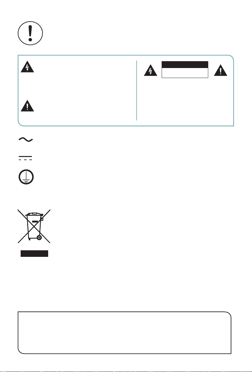
This symbol alerts user about the
presence of a dangerous voltage not
isolated inside the product which can
be sufficiently powerful to constitute a
risk of electrocution.
This symbol alerts user about the
presence of important operating
instructions and maintenance in the
document enclosed in the package.
AC voltage: This symbol indicates that the rated voltage marked with the
symbol is AC voltage.
DC voltage: This symbol indicates that the rated voltage marked with the
symbol is DC voltage.
Class I product: 75''/ 86'' requires a safety connection of protective earthing
(ground).
In no case the user is allowed to operate
Only a qualified technician is entitled to
ATTENTION
RISK OF SHOCK
ELECTRIC
Do not open the back cover.
inside the device.
operate.
Disposal of Used Electrical & Electronic Equipment
Packaging and electrical goods should be recycled appropriately, and
not treated as household waste. Please dispose of this equipment at
your applicable collection point for the recycling of electrical & electronic
equipment waste. By ensuring the correct disposal of this product,
you will help prevent potentially hazardous to the environment and to
human health, which could otherwise be caused by unsuitable waste
handling of this product. The recycling of materials will help conserve
natural resources. Please do not therefore dispose of your old electrical
and electronic equipment with your household waste. For more detailed
information about recycling of this product, please contact your local city
office, your household waste disposal service or the shop where you
purchased the product.
Warning!
Stability Hazard
The device set may fall, causing serious personal injury or death.
To prevent injury, this device set must be securely attached to
thewall in accordance with the installation instructions.
II
Page 4

Safeguards
Please read the following safeguards for your device and retain for future reference.
Always follow all warnings and instructions marked on the device.
1. A note about safety and operating instructions
Read and follow all safety and operating instructions, and retain them safely for future
reference.
2. Heed Warnings
Adhere to all warnings on the appliance and in the operating instructions.
3. Cleaning
Unplug the device from the wall outlet before cleaning. Do not use liquid, abrasive, or
aerosol cleaners. Cleaners can permanently damage the cabinet and screen. Use a
lightly dampened cloth for cleaning.
4. Water and Moisture
Avoid dripping or splashing of liquids onto the product. Objects filled with liquids, such
as vases, should not be placed on the product.
5. Ventilation
Slots and openings in the cabinet are provided for ventilation, to ensure reliable
operation of the device and to protect it from overheating. Do not cover the ventilation
openings in the cabinet and never place the set in a confined space such as built-in
cabinet unless proper ventilation is provided. Leave a minimum 10cm gap all around
the unit.
6. Power Source
This device should be operated only from the type of power source indicated on the
marking label. If you are not sure of the type of power supplied to your home, consult
your appliance dealer or local power company.
7. Power-Cord Protection
Power- supply cords should be routed so that they are not likely to be walked on or
pinched by items placed upon or against them, paying particular attention to cords at
plug, wall outlets, and the point where they exit from the device. MAIN plug is used as
the disconnect device, the disconnect device shall remain readily operable.
8. Lightning
For added protection for this device during a lightning storm, or when it is left
unattended and unused for long periods of time, unplug it from the wall outlet and
disconnect the cable system. This will prevent damage to the device due to lightning or
power-line surge.
III
Page 5

9. Overloading
Do not overload wall outlets and extension cords as this can result in a risk of fire or
electric shock.
10. Object and Liquid Entry
Never push objects of any kind into this device through openings as they may touch
dangerous voltage points or short-out parts that could result in fire or electric shock.
Never spill liquid of any kind on or into the device.
11. Servicing
Do not attempt to service this device yourself as opening or removing covers may
expose you to dangerous voltage or other hazards. Refer all servicing to qualified
service personnel.
12. Damage Requiring Service
Unplug the device from the wall outlet and refer servicing to qualified service personnel
under the following conditions:
(a) When the power - supply cord or plug is damaged.
(b) If liquid has been spilled, or objects have fallen into the device.
(c) If the device has been exposed to rain or water.
(d) If the device does not operate normally by following the operating instructions.
Adjust only those controls that are covered by the operating instructions as
an improper adjustment of other controls may result in damage and will often
require extensive work by a qualified technician to restore the device to its normal
operation.
(e) If the device has been dropped or the cabinet has been damaged.
(f) When the device exhibits a distinct change in performance - this indicates a need
for service.
13. Replacement Parts
When replacement parts are required, be sure the service technician has used
replacement parts specified by the manufacturer or have the same characteristics as
the original part. Unauthorized substitutions may result in fire, electric shock or other
hazards.
14. Safety Check
Upon completion of any service or repair to the device, ask the service technician to
perform safety checks to determine that the device is in safe operating condition.
15. Heat
The product should be situated away from heat sources such as radiators, heat
registers, stoves, or other products (including amplifiers) that produce heat.
IV
Page 6
16. Fire
The product should be situated away from naked flame sources such as lighted candle.
17. Off-gassing
The device smells of plastic is normal and will dissipate over time.
Incorrect replacement of the battery may lead to the risk, including the replacement of
another similar or the same type. Do not expose batteries to heat such as sun or fire or
something like that.
The device should not be exposed to dripping and spraying and it cannot be placed
under objects filled with liquids.
MAIN plug on the power cord is used as the disconnect device, the disconnect
deviceand socket-outlet shall be easily accessible.
Apparatus with CLASS I construction(75''/ 86'') shall be connected to a MAINS socket
outlet with a protective earthing connection.
V
Page 7
Start Guide
Precautions for Installation
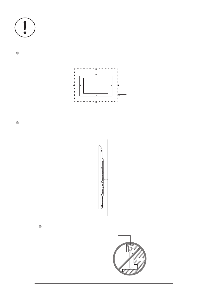
As shown in the figure below, leave a ventilation space around the device.
When mounted on the wall:
10cm
10cm10cm
Please leave this space
10cm
When installing this device on a vertical wall, the distance A between the product
and the wall should be kept at least 10cm to facilitate ventilation.
A
around the device.
Do not install the device as shown below.
Hinder air circulation
Wall
Insufficient ventilation will overheat the device and may cause
damage to the device and even fire.
VI
Page 8

CONTENTS
CONTENES ............................................................................................................... 1
Accessories List......................................................................................................... 2
Wall Mount (Optional) ................................................................................................ 2
Remote Control ......................................................................................................... 6
Control Panel ............................................................................................................. 9
Terminal Introduction ............................................................................................... 10
Initial Startup............................................................................................................ 12
Setting ..................................................................................................................... 13
RS232...................................................................................................................... 23
Miscellaneous .......................................................................................................... 33
Specications .......................................................................................................... 34
1
Page 9

1
NOTE
Items may di�er in di�erent locations
Display design and accessories may di�er from the images shown.
Remote Control × 1 Battery(AAA) × 2
Quick Setup Guide
RS232 Converter Cable ×1(Optional)
Power Cord (It depends on the regions or countries.)
Accessories List
× 1 Warranty Card×1(Optional)
2
1. Before installing the wall-mount bracket, rst place the machine on a secure and
clean desktop with soft protective cloth. Confirm that the desktop is solid and
reliable since the machine is heavy.
2. Remove the wall-mount screws in the wall-mount holes of the rear shell. (Ignore
this step in the absence of wall-mount screws. )
3. To avoid damage of the machine, please install the wall mount strictly in the
sequence of rollers, wall-mount bracket and wall-mount screws.
4. Before hanging the machine, please conrm that the wall-mount bracket is installed
securely without looseness.
5 Slowly peel o� the protective tape around the front shell.
Wall Mount (Optional)
2
Page 10
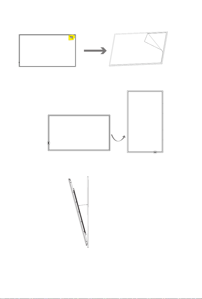
6 Slowly peel o� the panel protective lm on the machine by folding it 180 degrees
along the torn lm label.
Statement
【
•
To use this device in portrait mode, rotate it counterclockwise in reverse until the
power indicator light is as shown in the following gure.
Note
【
•
This device can tilt up to 15 degrees forward from a vertical wall.
】
】
15°
•
The pictures are for reference only. For detailed information on installing wall
mounted brackets, please refer to the manual provided with the wall mounted
bracket.
3
Page 11
Note
【
】
•
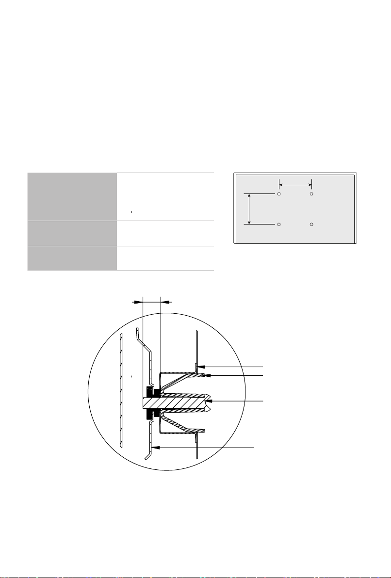
This machine is used in conjunction with Hisense LG400030D (32''/43''/50''/55''/65''
) and LG60060BE (75''/86'') wall mounted brackets; Using non designated wall
mounted brackets together may cause instability and injury.Product defects caused
by unauthorized installation by Hisense are not covered by the warranty.
•
If installation instructions are not followed or non Hisense authorized installation
services or accessories are used, there may be safety hazards (including but not
limited to product falling or falling o�) and personal injury or property damage may
occur. Such damage or loss is not caused by Hisense Company and should be
borne by the corresponding party at fault.
•
When using wall mounted installation, to avoid damage to the device or personal
injury, please install at an angle of less than 15 ° on a vertical wall.
VESA wall mount
standard (mm)
Diameter of wall-
mount screw (mm)
Number of wall
mounting holes
200×200 (32'')
300×300 (43''/50''/55'')
400×400 (65'')
600×400 (75''/86'')
M6
4
H
A
B
Schematic diagram of wall
mounting holes
Rear shell
Cushion block
Screw
LCD sreen
4
Page 12

Note
【
】
•
Only the installation specication of the wall mount is described here; the appearance of rear shell is for schematic purpose only.
•
The screw installation depth in the wall-mount holes of the rear shell , H is : 8.0-
10.0mm(32''); 12.0-13.0mm(43''/75''/86'');11.0-12.5mm(50''/55''/65'');
overlong screws will cause irreparable damage to the equipment.
•
If the intactness of the machine cannot be guaranteed during wall mounting, please
contact professional installation personnel or technical support personnel.
•
This wall mount is suitable for concrete and brick walls. For plank and plasterboard
walls, special reinforcement is required instead of directly using the wall mount.
Ensure that a single expansion bolt xed in the wall can bear over 1/3 of the overall
weight of the machine.
5
Page 13
3
Remote Control
Button name Button Description
Power Power on/o�
Source Input source menu
Number buttons.
0-9 -
*
#
Rewind Video playback page: rewind
Stop Video playback page: stop
Play
Forward Video playback page: forward
Lock
Setting Call the Settings menu
Use to enter a PIN, enter a Date,
etc.
Video play page: pause
Video pause page: play
Unlock the remote control
Key combination:
lock+ok+ok+lock
Up Move to the upper menu
Down Move to the lower menu
Left Move to the left menu
Right Move to the right menu
OK Conrm a menu selection.
Back Back to the previous menu
Exit Exit the current page
Volume +
Volume -
Home
Mute/Unmute
6
Increase the volume by 1 and
pop up the volume bar
Decrease the volume by 1 and
pop up the volume bar
A shortcut button to Home
screen
Mute on: pop up the mute icon
Mute o�: The mute icon
disappears and the current
volume is displayed.
Page 14
BRI+
BRI -
Setting – Display - Picture mode
-Customization – Black grade
APPS Open all apps
White Balance
Setting – Display – Advanced
setting – White balance
Device Info Setting – System – About
File Manger Open File Manager
VisionInfo Open VisionInfo
1. In All Apps, Media Center and
Media Autoplay pages, press
Menu
"Menu" button to enter editing mode;
2. Press "menu”button on other
pages to call out the shortcut menu.
Mutil-Screen
Setting – Display – Multi-screen display
Browser Open browser
Backlight Setting – Display - Brightness
Screen Rotation
Setting – Display – Screen
rotation
Network Setting - Network
Sound mode Setting – Sound – Sound mode
7
Page 15

Battery replacement method
1. Please open the battery cover by separating it from the remote control body at the
battery cover grommet.
2. Load two #7 1.5V alkaline batteries, noting that the positive (+) and negative (-)
terminals of the batteries must match the positive (+) and negative (-) terminals in
the battery compartment.
3. Close the battery cover from the bottom to the top until it fits perfectly into the
remote control body.
Effective range
1. Remote Control Distance : Remote control is e�ective within 8 metres from the
front.
2. Remote control angle: Take the remote control receiving window of this machine
as the apex, at a distance of 6 metres, the controlled angle is not worse than ±30
degrees in the left-right direction, and not worse than ±15 degrees in the vertical
up-down direction.
Note
【
】
•
Replace the batteries if the remote control does not operate properly, is unstable or
cannot control the unit remotely.
•
If you do not use the remote control for a long time or if the batteries are exhausted, please remove the batteries. (Used batteries pollute the environment, so
please dispose of them properly.)
•
In order to achieve the best remote control reception e�ect, please point the remote control transmitter window to the remote control receiver window position of
this unit for remote control operation.
8
Page 16
4
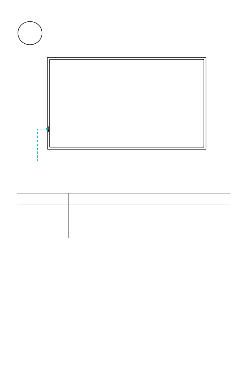
Remote sensor /
Power indicator
Name/Operation Function
Remote receiver
Indicator
Control Panel
Receive signals transmitted by the remote control via this
window.
When the machine is on, the indicator light is white; when it
enters sleep mode, the indicator light is red.
[Note]
•
The appearance is subject to the actual product.
•
Since power outage and system processing takes some time, DO NOT power
on and off the machine in rapid succession; otherwise the machine may work
abnormally.
9
Page 17
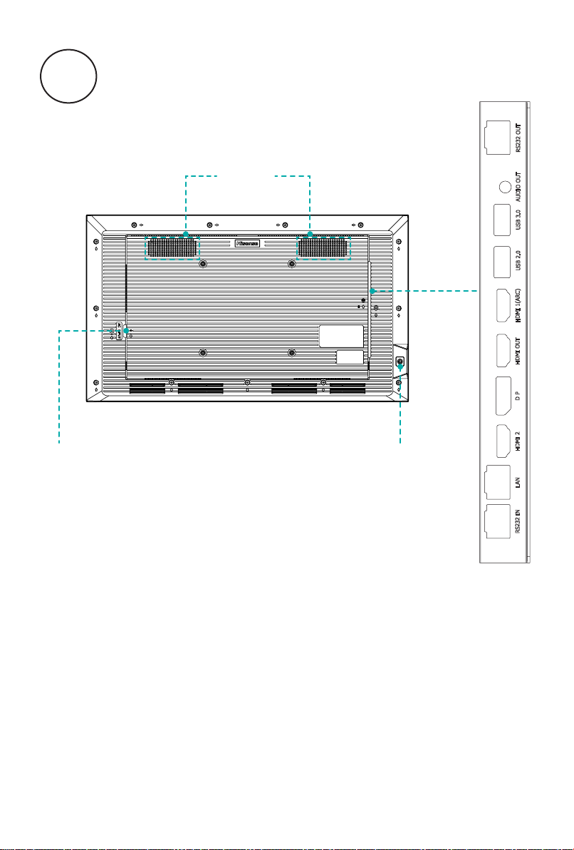
5
Terminal Introduction
RS232 OUTUSB 2.0
SPEAKER
AUDIO OUT
USB 3.0
HDMI 1(ARC)
AC INPUT
KEY
[Note]
The rear view is for reference only, please subject to the actual product.
·
RS232 port: It is for serial communication control of the machine.
·
It is possible that some external devices cannot be connected to the machine due
·
to individual di�erence. In such case, please replace the signal line with a suitable
one or add an adapter cable matching the port.
10
HDMI 2 D P HDMI OUT
RS232 IN LAN
Page 18

Port Name Function descriptionunction
USB standard port is provided with this machine; it can also
USB2.0
USB3.0
be used to connect a standard USB2.0 device, such as hard
disk drive and USB ⿿ash drive.
USB standard port is provided with this machine; it can also
be used to connect a standard USB2.0/USB3.0 device, such
as hard disk drive and USB ⿿ash drive.
HDMI1(ARC)
HDMI2
HDMI OUT
LAN
RS232 OUT It is the output port of the serial communication command.
RS232 IN It is the input port of the serial communication command.
AUDIO OUT It can be used to connect a headphone.
DP It can be used to connect an external device with DP port.
It can be used to connect an external device with HDMI port,
such as STB, player, or PC with HDMI output.
It can be used to connect an external device with HDMI port,
such as STB, player, or PC with HDMI output.
When HDMI2 or DP has signal input, HDMI OUT can output
HDMI2 or DP input signals; it can be used to connect other
display device with HDMI port.
It can be used to connect a network cables so as to access
the Internet.
[Note]
The rear view is for reference only, subject to the actual product.
·
It is possible that some external devices cannot be connected to the machine due
·
to individual di�erence. In such case, please replace the signal line with a suitable
one or add an adapter cable matching the port.
11
Page 19

6
Initial Startup
1 Startup/Shutdown
·
Connect the power cord of the machine to a 100-240V AC power outlet.
·
In power-on state, press the
will enter sleep mode. To watch normally, simply press again the
on the remote control.
STANDBY key
on the remote control; the machine
STANDBY key
[Note]
·
After pull o� the power cord, there should be an interval of at least 5s before restart
to prevent abnormality of the machine.
2 Adjust Local Settings
Use of the setting function can satisfy your di�erent needs and allow you to fully
enjoy the audiovisual e�ect brought by the machine.
You can adjust image and sound, set network connection and perform other
operations from here.
·
In menus at different levels, you can perform the following operations using the
remote control:
Press the
Press the
Press the
Press the
·
Press the
arrow keys
OK key
LEFT/RIGHT key
UP/DOWN key
key
to go back to the previous menu.
to select each option
to conrm operation or enter the sub-menu
to adjust values
to adjust options
12
Page 20

7
1
Calling Methods:
Press the
2
Setting:
Network
2nd 3rd Description
Setting
SETTING button
on the remote control to enter the setting interface.
Ethernet Automatic IP
acquisition
Manual IP Users are connected to a wired network and
MAC address Showcase a wired Mac
Wi-Fi On/O� The wireless network has two states: on and o�,
MAC address Showcase Wireless Mac Address
Available network Display a list of currently connectable WiFi.
-Wired priority, connects automatically when
wired is plugged in.
-Cannot be turned on when not connected to a
wired network.
-By default, the IP address is obtained
automatically.
can also manually congure an IP address for
Internet access.
and is on by default.
-The WiFi list is automatically refreshed every
10s.
-Shows the current status of each SSID:
Connected, Not Connected or No Internet
Access.
-For connected networks, click to view the IP
address (including the IPV6 address) or to
disconnect; for unconnected networks, click
to enter a password to connect, or open the
Advanced Settings and select Manual Settings.
Network Diagnostic
Add other network Manually add the network you want to connect
to.
Detects the current network connection status.
13
Page 21

Hotspot On/O� -The hotspot has two states, on and off, and is
off by default.
-Note: Hotspot and wireless network are
mutually exclusive, i.e., if the hotspot is on, the
wireless network is automatically off if it is on;
Name and
password
Enter the name and password of the hotspot you
want to connect to
Advanced setting Users can select the encryption method and
channel in the advanced settings
Bluetooth On/O� Bluetooth has both on and o� states, and is o�
by default.
Paired devices -Show paired devices.
-Note: Users can click on the device to cancel
the pairing.
Available devices -Show the list of currently searched Bluetooth
devices.
-Note: Users can perform pairing operation by
clicking the device.
Search Equipment Users can start the search function by clicking
the "Available Devices" button to search for
Bluetooth devices around them. Once a device
is searched, it will be displayed in the "Available
Devices" list.
Wi-Fi Display -Support Miracast protocol.
-Note: You need to open this page to search the
device to cast screen.
14
Page 22

Display
2nd 3rd Description
Brightness Backlight brightness, range 0-100
Auto adjust Automatically adjusts the brightness of the whole
backlight according to the light sense, and is on
by default.
Image mode Standard, Text,
Bright, Natural,
HDR
-Normal videos correspond to five image
modes: Standard, Bright, Natural, Text, and
Customization.
-When HDR video is played back, the image
mode automatically switches to HDR standard
mode.
Customization -Black Level: This parameter has a value range
of 0-100 and is used to describe the degree of
black expression in the image.
-Contrast: The value of this parameter ranges
from 0 to 100 and is used to describe the
contrast between light and dark of the image.
-Chroma: The value of this parameter ranges
from 0 to 100, and is used to describe the
degree of colour performance of the image.
-Sharpness: The value of this parameter ranges
from 0 to 20, which is used to describe the
degree of detail performance of the image.
-Colour Temperature: This parameter has ve
grades, namely, Cool, Cooler, Standard,
Warmer and Warmer, which are used to
describe the tonal performance of the image.
-Noise Reduction: This parameter has four
levels, namely O�, Low, Medium and High,
and the default level is Medium, which is used
to describe the degree of noise reduction of
the image.
Screen rotation Landscape -Rotation of the whole machine content, i.e. the
signal display is rotated synchronously with
Vertical
the menu display.
-Provides two angles, lanscape and vertical, the
default is lanscape .
Menu rotation Landscape -Only menu shows rotation.
Vertical
-Provides both lanscape and vertical angles,
default lanscape.
15
Page 23

Advanced
setting
Zoom -Lanscape screen: full screen, standard, zoom 1,
zoom 2, point to point.
-Vertical screen: full screen, custom.
Dynamic Contrast On, o�, default on.
Luminance dynamic
Auto, Limit, All, default Auto.
range
White balance Users can adjust the white balance of the video
image
-2-point and 10-point white balance can be
selected for adjustment;
-2-point white balance adjusts the white balance
sub-items of the image: red gain, green gain,
blue gain, red deviation, green deviation,
blue deviation. The adjustment range is (-30
--- +30), and the default is 0.
-10-point white balance adjusts the image's
options including LEVEL selections: 1-10;
red, green, blue, with an adjustment range of
(-30 --- +30) and a default of 0.
Gamma -Adjust the centre brightness of the image.
-The user has the option to turn gamma on or
off. Sub options include: 1.8, 2.0, 2.2, 2.4.
Colour correction Users can adjust the colour of the video image.
1. Adjustment sub-items: red, green, blue,
cyan, yellow, purple, skin tone hue, colour
saturation, brightness options.
2. Adjustment range (-15 --- +15), default is 0.
3. The setting e�ect takes e�ect instantly.
Multi-screen display Used in multiple screen splicing scenarios.
1. Set the position and display content of each
screen through the four options of "Horizontal
Ratio", "Vertical Ratio", "Screen Position" and
"Edge Masking". Set the position and display
content of each screen;
2. Horizontal and vertical settings for the number
of rows and columns of the splicing settings,
the default is 1 row and 1 column, range 1-15.
3. Screen Position is the position of the row and
column where the screen is located.
4. Edge Masking Setting sub-option for On and
O�, default O�, when turned on, the splicing
position image is used to crop o�.
Image parameter
reset
Rest preset values for image settings.
16
Page 24

Sound
2nd 3rd Description
Sound mode Standard, Cinema,
Music, Meeting,
Customization
Output device Device speakers,
HDMI ARC, USB
sound equipment
Advanced
setting
Automatic volume
control
Balance Users can adjust the left/right balance of the
Maximum Volume/
Minimum Volume
Sound parameter
reset
Users can adjust several sound modes preset by
the unit: standard, cinema, music, meeting,
customization.
1.Default standard.
2.Custom support 5-band equalisation
adjustment: 120Hz, 500Hz, 1.5kHz, 5kHz,
10kHz.
Users can adjust the sound output device
selection.
1. Output devices include: device speakers,
HDMI ARC, Bluetooth devices, USB audio
devices
2. Default native speakers.
When a device type is selected, other types of
audio devices do not output sound
Users can adjust the automatic volume control
switch.
1. Adjustment items: on, o�, default is o�.
sound output.
1. Adjustment range -10 to 10, default 0.
Users can set the maximum and minimum
volume.
Users has the option to restore the sound
settings to the factory preset state.
17
Page 25

Switch on/o�
2nd 3rd Description
Switch-on
source
Memory, Home,
HDMI1, HDMI2, DP,
Media Autoplay
1. Media autoplay option is displayed according
to the playlist, it is not displayed when the
playlist is empty.
2. Default boot source is home.
Power on mode Boot, Standby, Last Default boot.
Wake-on LAN Switch on, switch o� Users can wake up the whole machine through
wired network.
1. When it is on, you can wake up the whole
machine through the network, and o�, you
can't wake up.
2. O� by default.
Sleep mode
settings
Switch on, switch o� Users can set whether or not to enter the
hibernation state through the hibernation menu.
Turn-on delay Switch on, switch o� Sets the power-on delay default value. Setting
range 2-255s.
Timed switch
on/o�
Boot, Shutdown Users can activate and deactivate the timer on/
o� function. The clock sets hours and minutes
in a 24-hour manner, and up to three di�erent
switch-on/switch-o� time points can be set per
day (each switch is a time period).
No signal
standby
O�, 30S, 1 minute,
5 minutes, 10
minutes, 15
Automatic standby with no signal from the
source.
Default 10 minutes.
minutes, 30
minutes, 60 minutes
No operation
standby
O�, 10 minutes,
15 minutes,
Auto standby for Android without operation.
Default 15 minutes.
30 minutes, 60
minutes, 90
minutes, 120
minutes
18
Page 26

Signal management
2nd 3rd Description
Failover switch on, switch o� The sub-options contain On and O�, with O�
being the default. When on, you can select
master signal source and slave signal source.
1. Among the channels supported by the whole
machine, select two signal sources as master
signal source and slave signal source;
2. When there is no signal from the master
signal source and there is signal from the
slave signal source, it will automatically jump
to the slave signal source;
3. When there is no signal from the master signal
source and no signal from the slave signal
source, out of the no signal screen saver;
4. when the signal from the main signal source
is restored, automatically switch to the main
signal source;
5. When the master signal source is not restored
and the slave signal source is restored,
automatically switch to the slave signal
source;
Auto switch
switch on, switch o� The device automatically switches channels
source
Automatic
switch on, switch o� -Supports external signal for whole machine
wake-up
HDMI version HDMI standard,
HDMI enhanced
when it detects a new signal access.
Enabled by default.
standby wake-up.
-Enabled by default.
-This option unies the control of the standby
wake-up function for HDMI and DP signals.
Default HDMI standard
19
Page 27

HDMI CEC CEC switch -On, o�, default o�.
-When the control switch is on, the HDMI CEC
control takes e�ect and the standby control,
auto power on, and remote control switches
are highlighted.
Standby control -On, o�, default grey on.
-When the whole machine is switched o� by
remote control, the external HDMI CEC device
also enters the standby state.
Automatic power-on -On, o�, default set grey on.
-When switching on the whole machine, the
CEC device will automatically switch on
after receiving the command from the whole
machine.
Remote control -On, o�, default grey on.
-Through the remote control, you can control the
external HDMI CEC device, such as up, down,
left, right, OK, return.
Homepage
setting
Users can customise the homepage according
to their needs. Supports browsers, Screen Cast
(provided that the multi-screen interactive service
lock is on) and installed third-party applications
Serial port ID
setting
-User can set the ID for serial communication
through the setting menu.
-ID setting data range is: 1-255.
20
Page 28

System
2nd 3rd Description
Language Simplied Chinese,
English, French,
German, Polish,
-Switches the system language.
-The default language is set according to the
shipping country.
Sipan, Russian,
Italian, Finnish,
Norwegian,
Swedish, Israeli,
Arabic, Thai, Malay,
Bahasa Indonesia
Input method kika input method Currently there is only one kika input method.
Country/Time
Select country and time zone
zone selection
Time and date Network
synchronization
Select whether to enable network
synchronisation of the system date and time.
Date Modify the system date.
Time Modify the system time.
Upgrade and
update
Device upgrade -Detect the availability of new system software
versions through the network.
-Performs an OTA upgrade of the entire system.
USB upgrade and
update
-Detect the availability of updatable system
software through the USB port.
-Upgrade the whole system.
Over
temperature
protection
USB di�erential
upgrade
Device internal
temperature
Primary protection On by default, automatically reduces backlight
Di�erential upgrade of the complete system via
USB interface.
Display the internal temperature of the unit.
brightness by half when the temperature reaches
70 degrees Celsius.
Secondary
protection
(Forced on) Prompts to switch o� when
temperature reaches 90 degrees Celsius.
Level 3 protection (Forced on) Automatically switches o� when the
temperature reaches 100 degrees Celsius.
Reset Restore all options and hard disc space of the
device to the initial default state.
Disclaimer User agreement Displaying user agreement.
Privacy policy Showcasing the privacy policy.
21
Page 29

About Device name -Display the name of the local machine.
-The device name supports customisation.
Serial number Display the SN code of unit.
Device ID Display device ID.
Android version Display the current system Android version.
System capacity Display system capacity.
Software version Display the current system software version
number.
Wired MAC Display wired mac.
Wireless MAC -Display the mac address after connecting to the
wireless network.
-Note: Display the default mac
02:00:00:00:00:00:00 when wireless is not
connected.
Booting running
Records and displays the power-on run time.
time
Issue report Export logs to a storage device via the USB port.
22
Page 30
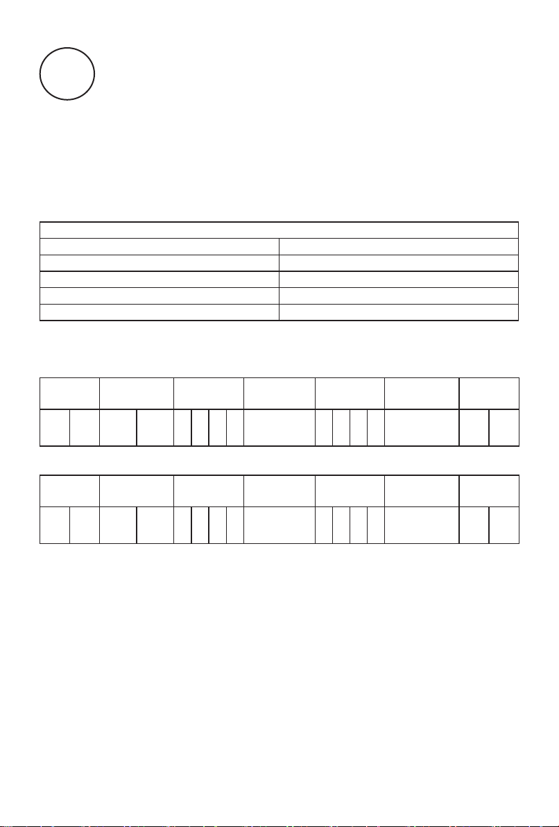
8
RS232
Serial Port State
port commands sent by the external controller. See the table below for the specic
command protocol.
When the serial port is open, the machine can receive serial
:
Data Parameters
DM-SERIES
Baud Rate 9600
Data length (bits) 8
Parity None
Stop bit 1
Flow control None
Command Format
PC -> TV:
Header
(2 Bytes)
DD FF BB CC
TV -> PC:
Header
(2 Bytes)
AB AB CD CD
Length
(2 Bytes)
Length
(2 Bytes)
Command
(4 Bytes)
Command
(4 Bytes)
Monitor ID
(1 Byte)
Monitor ID
(1 Byte)
Data
(N Bytes)
Data
(N Bytes)
Checksum
(1 Bytes)
Checksum
(1 Bytes)
End
(2 Bytes)
End
(2 Bytes)
[Note]
·
Length is the number of bytes of Command, Data and Checksum.
·
Checksum is XOR of Length, Command, Monitor ID and Data.
23
Page 31
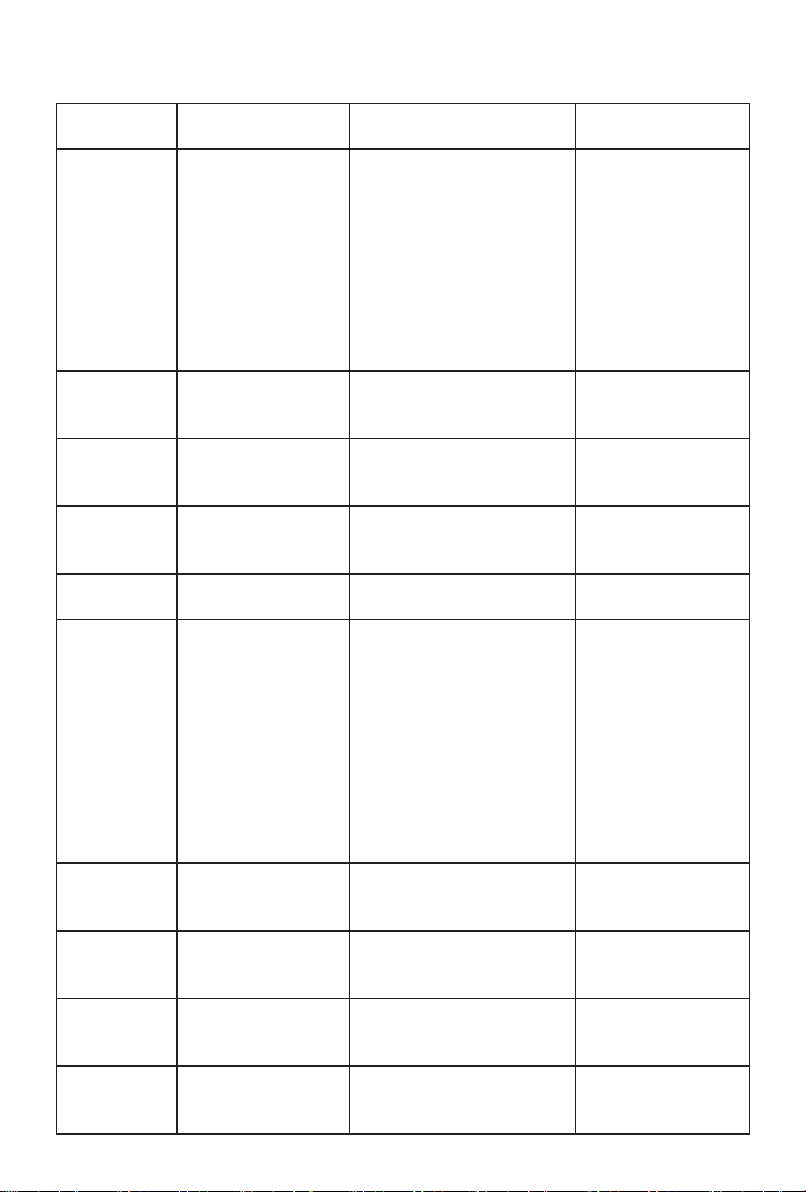
RS232 Command
Description Command (HEX
Bytes)
Power On DD FF 00 08 C1 15
00 00 xx BB BB yy
BB CC
Power O� DD FF 00 08 C1 15
00 00 xx AA AA yy
BB CC
Screen O� DD FF 00 07 C1 31
00 00 xx 00 yy BB
CC
Screen On DD FF 00 07 C1 31
00 00 xx 01 yy BB
CC
Reboot DD FF 00 06 C1 1E
00 00 xx yy BB CC
Set AC Power
On Mode
DP Input DD FF 00 07 C1 08
VGA Input DD FF 00 07 C1 08
HDMI1 Input DD FF 00 07 C1 08
HDMI2 Input DD FF 00 07 C1 08
DD FF 00 07 C1 FF
00 09 xx zz yy BB
CC
00 00 xx 16 yy BB
CC
00 00 xx 17 yy BB
CC
00 00 xx 0E yy BB
CC
00 00 xx 0F yy BB
CC
Example (PC -> TV ID 01) TV -> PC
DDFF0008C115000001
BBBBDDBBCC
Tips: The range of this
command’s ID is 0x01-
0x34.
DD FF 00 08 C1 15 00 00
01 AA AA DD BB CC
DD FF 00 07 C1 31 00 00
01 00 F6 BB CC
DD FF 00 07 C1 31 00 00
01 01 F7 BB CC
DD FF 00 06 C1 1E 00 00
01 D8 BB CC
DDFF0007C1FF00090
10031BBCC
zz: power on mode. 00
– direct, 01 – last, 02 –
standby
direct: DD FF 00 07 C1 FF
00 09 01 00 31 BB CC
last: DD FF 00 07 C1 FF 00
09 01 01 30 BB CC
standby: DD FF 00 07 C1
FF 00 09 01 02 33 BB CC
DDFF0007C10800000116
D9BBCC
DDFF0007C10800000117
D8BBCC
DDFF0007C1080000010
EC1BBCC
DDFF0007C1080000010
FC0BBCC
24
AB AB 00 08 C1 15
00 00 xx BB BB yy
CD CD
When TV is in
standby sate, send
this command will
get one feedback
from TV, once TV
starts up, it will send
feedback again.
AB AB 00 08 C1 15
00 00 xx AA AA yy
CD CD
AB AB 00 07 C1 31
00 00 xx 00 yy CD
CD
AB AB 00 07 C1 31
00 00 xx 01 yy CD
CD
AB AB 00 06 C1 1E
00 00 xx yy CD CD
AB AB 00 07 C1 FF
00 09 xx zz yy CD
CD
AB AB 00 07 C1 08
00 00 xx 16 yy CD
CD
AB AB 00 07 C1 08
00 00 xx 17 yy CD
CD
AB AB 00 07 C1 08
00 00 xx 0E yy CD
CD
AB AB 00 07 C1 08
00 00 xx 0F yy CD
CD
Page 32
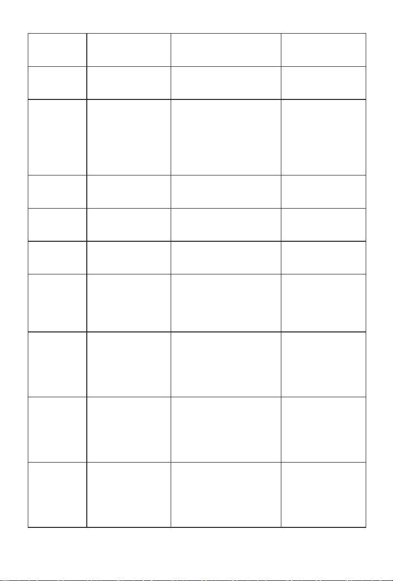
PC Input DD FF 00 07 C1 08
00 00 xx 0C yy BB
CC
DVI Input DD FF 00 07 C1 08
00 00 xx 09 yy BB
CC
Set Screen
Aspect Ratio
DD FF 00 07 C1 35
00 00 xx zz yy BB
CC
Once this command
is set, reboot TV,
it will show with
expected ratio
Set Mute DD FF 00 07 C1 26
00 00 xx 01 yy BB
CC
Set Unmute DD FF 00 07 C1 26
00 00 xx 00 yy BB
CC
Set Volume DD FF 00 07 C1 27
00 00 xx zz yy BB
CC
Set Backlight
Brightness
DD FF 00 08 C1 32
00 00 xx 06 zz yy BB
CC
DDFF0007C1080000010
CC3BBCC
DDFF0007C1080000010
9C6BBCC
ex: set screep ratio 90
degrees
DDFF0007C1350000010
9FBBBCC
zz = 00 - 0 degree, 01 - 90
degree
DDFF0007C1260000010
1E0BBCC
DDFF0007C1260000010
0E1BBCC
DDFF0007C1270000010
1E1BBCC
zz: volume range 0-100
ex: set brightness to 32 - zz
= 0x20
DDFF0008C1320000010
620DCBBCC
AB AB 00 07 C1 08
00 00 xx 0C yy CD
CD
AB AB 00 07 C1 08
00 00 xx 09 yy CD
CD
AB AB 00 07 C1 35
00 00 xx zz yy CD
CD
AB AB 00 07 C1 26
00 00 xx 01 yy CD
CD
AB AB 00 07 C1 26
00 00 xx 00 yy CD
CD
AB AB 00 07 C1 27
00 00 xx zz yy CD
CD
AB AB 00 08 C1 32
00 00 xx 06 zz CD
CD
Set Backlight
Brightness
Auto Adjust
DD FF 00 07 C1 34
00 00 xx zz yy BB
CC
Set Date DD FF 00 09 C1 1C
00 00 xx zz zz zz yy
BB CC
Set Time DD FF 00 09 C1 1D
00 00 xx zz zz zz yy
BB CC
ex: set brightness auto
adust o�
DDFF0007C1340000010
0F3BBCC
zz = 00 - o�, 01 - on
ex: set date to 23.Jan.2
DDFF0009C11C0000011
7010
2C1BBCC
zz zz zz = Year Month Day
ex: set time to 12:25:2
DDFF0009C11D0000010
C1902C3BBCC
zz zz zz = Hour Minute
Second
25
AB AB 00 07 C1 34
00 00 xx zz yy CD
CD
AB AB 00 09 C1 1C
00 00 xx zz zz zz yy
CD CD
zz zz zz = FF FF FF
when error
AB AB 00 09 C1 1D
00 00 xx zz zz zz yy
CD CD
zz zz zz = FF FF FF
when error
Page 33
Set Schedule
for Power On
DD FF 00 09 C1 3E
00 00 xx tt zz zz yy
BB CC
ex: power on at 9:10 every
day
DDFF0009C13E0000010
1090AF5BBCC
tt = 00 - turn o� schedule,
01 - everyday
zz zz = Hour Minute
Tips: If the device has been
set to power on and o� at
a scheduled time, sending
this command will clear
the original settings, and
leaving only the one sent.
AB AB 00 09 C1 3E
00 00 xx zz zz zz yy
CD CD
Set Schedule
for Power O�
DD FF 00 09 C1 3F
00 00 xx tt zz zz yy
BB CC
Set
Brightness
DD FF 00 07 C1 36
00 00 xx zz yy BB
CC
Set Contrast DD FF 00 07 C1 37
00 00 xx zz yy BB
CC
current source must
be: DP, VGA, HDMI,
PC, DVI
Set
Sharpness
DD FF 00 07 C1 38
00 00 xx zz yy BB
CC
current source must
be: DP, VGA, HDMI,
PC, DVI
ex: power o� at 18:10 every
day
DDFF0009C13F0000010
1120AEFBBCC
tt = 0 - turn o� schedule, 1 -
everyday
zz zz = Hour Minute
Tips: If the device has been
set with a timed power on/
o� command, all previously
set power on/o� will be
turned o�
ex: set brightness to 32 - zz
= 0x20
DDFF0007C1360000012
0D1BBCC
ex: set contrast to 32 - zz =
0x20
DDFF0007C1370000012
0D0BBCC
ex: set sharpness to 32 - zz
= 0x20
DDFF0007C1380000012
0DFBBCC
AB AB 00 09 C1 3F
00 00 xx zz zz zz yy
CD CD
AB AB 00 07 C1 36
00 00 xx zz yy CD
CD
AB AB 00 07 C1 37
00 00 xx zz yy CD
CD
AB AB 00 07 C1 38
00 00 xx zz yy CD
CD
26
Page 34

Set Color
Temperature
Set Noise
Reduction
Set Image
Scaling
Set Picture
Mode
DD FF 00 07 C1 39
00 00 xx zz yy BB
CC
current source must
be: DP, VGA, HDMI,
PC, DVI
DD FF 00 07 C1 3A
00 00 xx zz yy BB
CC
current source must
be: DP, VGA, HDMI,
PC, DVI
DD FF 00 07 C1 3B
00 00 xx zz yy BB
CC
current source must
be: DP, VGA, HDMI,
PC, DVI
DD FF 00 07 C1 0F
06 00 xx zz yy BB
CC
ex: set colour temperature
to 32 - zz = 0x20
DDFF0007C1390000012
0DEBBCC
ex: set noise reduction to
High - zz = 0x03
DDFF0007C13A0000010
3FEBBCC
zz = 01 - low, 02 - medium,
03 - high, 04 - auto, 00 – o�
ex: set image scaling to
Full - zz = 0x03
DDFF0007C13B0000010
3FFBBCC
zz = 00 - full, 01 - 16:9, 02
- 4:3, 03 - scaling 1, 04 -
scaling 2, 05 - point to point
ex: set picture mode to
movie mode - zz = 0x03
DDFF0007C10F0600010
30CBBCC
zz = 00 - standard, 01 -
bright, 02 - soft, 03 - Movie,
04 - Text, 5 - gaming 12 –
natural
AB AB 00 07 C1 39
00 00 xx zz yy CD
CD
AB AB 00 07 C1 3A
00 00 xx zz yy CD
CD
AB AB 00 07 C1 3B
00 00 xx zz yy CD
CD
AB AB 00 07 C1 0F
06 00 xx zz yy CD
CD
Set Sound
Mode
Set Eye
Protection
Mode
VGA Auto
Adjust
DD FF 00 07 C1 FF
00 03 xx zz yy BB
CC
DD FF 00 07 C1 FF
00 1E xx zz yy BB
CC
DD FF 00 07 C1 01
00 00 xx yy BB CC
current source must
be VGA
ex: set sound mode to
standard mode - zz = 0x00
DDFF0007C1FF0003010
03BBBCC
zz = 00 - standard,01
- music, 02 - news, 08 -
movie, 10 - sports,20 -
custom, 30 - voice, 40 -
meeting
ex: set eye protection mode
on - zz = 0x01
DDFF0007C1FF001E010
127BBCC
zz = 00 - o�, 01 - on
ex: VGA Auto Adjust
DDFF0007C101000001C
6BBCC
zz = 00 - o�, 01 – on
27
AB AB 00 07 C1 FF
00 03 xx zz yy CD
CD
AB AB 00 07 C1 FF
00 1E xx zz yy CD
CD
AB AB 00 07 C1 01
00 00 xx yy CD CD
Page 35
Set anti-burn-
in (image
retention)
Set Power on
delay
DD FF 00 07 C1 33
00 00 xx zz yy BB
CC
DD FF 00 07 C1 3C
00 00 xx zz yy BB
CC
Set Video
Wall
DD FF 00 09 C1 0A
00 00 xx zz zz zz yy
BB CC
Set Static IP
Address of
LAN
DD FF 00 16 C1 1B
30 00 xx zz … zz yy
BB CC
Set USB Lock DD FF 00 07 C1 FF
00 0E xx zz yy BB
CC
Factory Reset DD FF 00 06 C1 10
00 00 xx yy BB CC
ex: set anti-burn-in on
DDFF0007C1330000010
1F4BBCC
zz = 00 - o�, 01 - on
ex: set power on delay to
10s
DDFF0007C13C0000010
AF1BBCC
zz = 00 - o�, others - delay
time, range: 2s - 255s
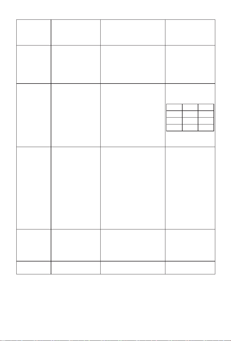
ex: vertical 3 devices,
horizontal 4 devices, device
position: 6
DDFF0009C10A0000010
30406C2BBCC
zz: how many devices in
vertical
zz: how many devices in
horizontal
zz: current device position
Ex: set IP 10.16.150.225,
subnet mask:
255.255.248.0, gateway:
10.16.144.1, DNS:
10.16.144.2
DDFF0016C11B3000010
A1096E1FFFFF8000A10
90010
A10900249BBCC
zz .. zz - 16 bytes, IP
address - 4 bytes, Subnet
mask - 4 bytes, gateway - 4
bytes, DNS - 4 bytes
ex: lock USB
DDFF0007C1FF000E010
036BBCC
zz = 00 - lock USB, 01 -
enable USB
DDFF0006C110000001D
6BBCC
AB AB 00 07 C1 33
00 00 xx zz yy CD
CD
AB AB 00 07 C1 3C
00 00 xx zz yy CD
CD
AB AB 00 09 C1 0A
00 00 xx zz zz zz yy
CD CD
1 2 3
4 5 6
7 8 9
10 11 12
AB AB 00 16 C1 1B
30 00 xx zz … zz yy
CD CD
AB AB 00 07 C1 FF
00 0E xx zz yy CD
CD
AB AB 00 06 C1 10
00 00 xx yy CD CD
28
Page 36
Query TV
Status
Query Screen
Status
DD FF 00 06 C1 28
00 00 xx yy BB CC
DD FF 00 06 C1 32
00 01 xx yy BB CC
Query Source DD FF 00 06 C1 1A
00 00 xx yy BB CC
Query SW
Version
Query
Backlight
DD FF 00 06 C1 1B
00 00 xx yy BB CC
DD FF 00 06 C1 3E
00 24 xx yy BB CC
Brightness
DDFF0006C128000001E
EBBCC
DDFF0006C110000001D
6BBCC
DDFF0006C11A000001D
CBBCC
DDFF0006C11B000001D
DBBCC
DDFF0006C13E000001F
8BBCC
AB AB 00 0C C1 28
00 00 xx zz zz zz zz
zz zz yy CD CD
zz: volume
zz zz: 05 01 - PC, 05
02 - DVI, 05 03 - DP,
05 04 - HDMI2, 05
05 - HDMI1, 08 01 -
VGA
zz: 00 - power on,
FF - power o�
zz: 01 - mute; 00 -
unmute
zz: 00 - no signal, 01
- has signal
AB AB 00 07 C1 32
00 01 xx zz yy CD
CD
zz: 00 - screen o�;
01 - screen on
AB AB 00 08 C1 1A
00 00 xx zz zz yy
CD CD
zz zz - source, refer
to user menu for
source denition
AB AB 00 09 C1 1B
00 00 xx zz zz zz yy
CD CD
zz zz zz - Year
Month Date
AB AB 00 LL C1 3E 00
24 xx zz zz yy CD CD
zz:01 - bright,02 -
soft, 03 - auto adjust,
04 - stereo frequency
conversion,05 -
Comfort frequency
conversion,06 -
custom
zz: when rst zz is
06 custom, this byte
means backlight
brightness value: 0-30
LL: when rst zz is zz,
LL = 08, otherwise, LL
= 07
29
Page 37
Query
Brightness
Query
Network
Status
Query Sound
Mode
Query AC
Power On
Status
Query IP
Address
Query Device
Temperature
Query Picture
Mode
DD FF 00 06 C1 36
00 01 xx yy BB CC
DD FF 00 06 C1 FF
00 16 xx yy BB CC
DD FF 00 06 C1 FF
00 02 xx yy BB CC
DD FF 00 06 C1 FF
00 08 xx yy BB CC
DD FF 00 06 C1 1B
20 00 xx yy BB CC
DD FF 00 06 C1 FE
00 00 xx yy BB CC
DD FF 00 06 C1 6D
00 00 xx yy BB CC
DDFF0006C136000101F
0BBCC
DDFF0006C1FF0016012
FBBCC
DDFF0006C1FF0002013
BBBCC
DDFF0006C1FF0008013
1BBCC
DDFF0006C11B200001F
DBBCC
DDFF0006C1FE0000013
8BBCC
DD FF 00 06 C1 6D 00 00
64 CE BB CC
30
AB AB 00 07 C1 36
00 01 xx zz yy CD
CD
zz is the brightness
value
AB AB 00 07 C1 FF
00 16 xx zz yy CD
CD
zz: 00 - no network
connection; 01 -
network connected
AB AB 00 07 C1 FF
00 02 xx zz yy CD
CD
zz = 00 - standard
,
01 - music, 02 -
news, 08 - movie,
10 - sports,20 -
custom, 30 - voice,
40 - meeting
AB AB 00 07 C1 FF
00 08 xx zz yy CD
CD
zz: 00 - power on;
01 - Last mode; 02 -
standby
AB AB 00 16 C1 1B
20 00 xx zz … zz yy
CD CD
zz zz zz zz - IP
address
zz zz zz zz - Subnet
mask
zz zz zz zz Gateway
zz zz zz zz - DNS
AB AB 00 07 C1 FE
00 00 xx zz yy CD
CD
zz: temperature in
centigrade
AB AB 00 07 C1 6D
00 00 xx zz yy CD
CD
zz: 00 – standard, 01
– bright, 06 – AI, 07 –
user, 02 – soft, 03 –
movie, 04 – text, 05 –
game, 12- nature
Page 38
Query USB
Status
Query Eye
Protection
DD FF 00 06 C1 6E
00 00 xx yy BB CC
DD FF 00 06 C1 FF
00 1D xx yy BB CC
Mode
Query SN DD FF 00 06 C1 FF
00 0B xx yy BB CC
Query Devicd IDDD FF 00 06 C1 FF
00 0D xx yy BB CC
Query MAC
Address
DD FF 00 06 C1 6C
00 00 xx yy BB CC
Query volume DD FF 00 06 C1 7D
00 00 xx yy BB CC
Query Serial
Port ID
DD FF 00 06 C1 1B
10 00 xx yy BB CC
Query brand DD FF 00 06 C1 FE
00 01 xx yy BB CC
Query model DD FF 00 06 C1 FE
00 02 xx yy BB CC
DD FF 00 06 C1 6E 00 00
64 CD BB CC
DDFF0006C1FF001D012
4BBCC
DDFF0006C1FF000B013
2BBCC
DDFF0006C1FF000D013
4BBCC
DDFF0006C16C000001A
ABBCC
DD FF 00 06 C1 7D 00 00
64 DE BB CC
DD FF 00 06 C1 1B 10 00
64 A8 BB CC
DD FF 00 06 C1 FE 00 01
64 5C BB CC
DD FF 00 06 C1 FE 00 02
64 5F BB CC
AB AB 00 07 C1 6E
00 00 xx zz yy CD
CD
zz: 00 - o�, 01 - on
AB AB 00 07 C1 FF
00 1D xx zz yy CD
CD
zz: 00 - O�; 01 - On
AB AB 00 1D C1 FF
00 0B xx zz…zz yy
CD CD
zz .. zz: 23 bytes
serial number
AB AB 00 26 C1 FF
00 0D xx zz…zz yy
CD CD
zz .. zz: 32 bytes
device ID
AB AB 00 0C C1 6C
00 00 xx zz…zz yy
CD CD
zz .. zz: 6 bytes
AB AB 00 07 C1 7D
00 00 xx zz yy CD
CD
zz: volume
AB AB 00 06 C1 1B
10 00 xx zz yy CD
CD
zz: serial port ID.
Settings -> signal
manager -> serial
port ID
AB AB 00 06 C1 FE
00 01 xx zz…zz yy
CD CD
zz…zz: brand. ex:
hisense (ASCII)
AB AB 00 06 C1 FE
00 02 xx zz…zz yy
CD CD
zz…zz: model name
31
Page 39
Send Remote
Controller Key
Code
DD FF 00 08 C1 17
00 00 xx zz zz yy BB
CC
Open Settings DD FF 00 06 C1 41
00 00 xx yy BB CC
Open Home DD FF 00 06 C1 FF
00 1A xx yy BB CC
Open CMS DD FF 00 06 C1 FF
00 13 xx yy BB CC
Open
ScreenShare
Turn on
Hotspot
Take
Screenshot
Freeze
Screen
DD FF 00 06 C1 43
00 00 xx yy BB CC
DD FF 00 06 C1 44
00 00 xx yy BB CC
DD FF 00 06 C1 4B
00 00 xx yy BB CC
DD FF 00 07 C1 0F
08 00 xx zz yy BB
CC
ex: send menu key: zz zz =
00 00
DDFF0008C1170000010
000DFBBCC
zz zz = 00 00 - Menu; 00
01 - UP, 00 02 - DOWN,
00 03 - LEFT, 00 04 -
RIGHT, 00 05 - OK, 00
06 - Return, 00 07 - Source
DDFF0006C1FF001A
0123BBCC
DDFF0006C1FF0013012
ABBCC
DDFF0006C1430000018
5BBCC
DDFF0006C1440000018
2BBCC
DDFF0006C14B0000018
DBBCC
DD FF 00 07 C1 0F 08 00
01 01 C1 BB CC
zz = 01 - freeze; 00 –
unfreeze
AB AB 00 08 C1 17
00 00 xx zz zz yy CD
CD
AB AB 00 06 C1 41
00 00 xx yy CD CD
AB AB 00 06 C1 FF
00 1A xx yy CD CD
AB AB 00 06 C1 FF
00 13 xx yy CD CD
AB AB 00 06 C1 43
00 00 xx yy CD CD
AB AB 00 06 C1 44
00 00 xx yy CD CD
AB AB 00 06 C1 4B
00 00 xx yy CD CD
AB AB 00 07 C1 0F
08 00 xx zz yy CD
CD
[Note]
·
The range of BoardID is from 01 to FF, supporting 255 machines to be networked
together. 00 is the broadcast address, the commands issued by this ID will be
executed by all MFPs, but the commands will not be returned.
·
When all the commands received from TV terminal are returned to PC terminal, the
start code should be changed to AB AB, and the end code should be changed to
CD CD.
·
Note for programming of control terminal: For power-on instruction, after poweron action is executed, it returns AB AB 00 08 C1 15 00 00 XX BB BB XX CD CD
(refer to the above table for the meaning of XX); if the instruction is not received, it
is necessary to send the power-on instruction again. after TV is turned on, the PC
will receive AB AB 00 08 C1 15 00 00 00 XX BB BB XX CD CD again, and then
the PC can send the control instruction. After the TV is switched on, the PC will
receive the command again, then the PC can send control commands to the TV; if
any command is not returned correctly, the interval between sending the command
again should be more than 500ms.
·
When TV is in sleep state, only power-on command and query command are
supported.
32
Page 40
9
Miscellaneous
1 Troubleshooting
Before preparation for repair, please check the following table to see if the cause of
problem you are encountering can be found.
If the problem still exits when you confirm that you are operating the product in strict
accordance with the this manual, you can consider contacting professional service
personnel for repair.
Symptom Solution
Check whether the power cord is connected to a
No sound or image
Sound and image interference
Blurred or snowy screen,
image distortion
Malfunction of remote control
·
wall outlet and whether the outlet is energized.
Check whether the power key is pressed.
·
Check the volume setting or whether it is muted.
·
Try finding out the electrical appliance affecting
·
the machine, and keep it away from the machine.
Try inserting the power plug of the machine to
·
another power outlet.
Check the position and connection of signal line.
·
Replace the batteries in the remote control.
·
After removing the batteries, press any key
·
several times, and then install new batteries.
Check the battery contacts.
·
Check whether any obstruction exists between the
·
display screen and the remote control.
Check whether the anode and cathode of batteries
·
are correctly installed.
2 Related Instructions
HDMI, HDMI High-Denition Multimedia Interface, and the HDMI
Logo are trademarks or registered trademarks of HDMI Licensing
Administrator, Inc. in the United States and other countries.
[Statement]
The pictures and descriptions in this manual are for reference only, please subject
·
to our available products. (This statement is valid throughout this manual)
Quality upgrade, product design and specification are subject to change without
·
prior notice.
The software content services applying to this product depend on the third-party
·
provider. It is possible that partial software cannot be used due to network, region,
service period or other problems, which has nothing to do with the product quality.
Please contact the third-party provider for relevant details.
33
Page 41
10
Model 32'' 43'' 50''
Product name Digital Signage
Specications
excluding
Size (mm)
(W×H×D)
Product weight (kg) 4.6 8.5 11.0
Visual picture
diagonal size (cm)
Display resolution 1920×1080 3840×2160 3840×2160
Product power 110W 130W 170W
Sound power 7W+7W 10W+10W 10W+10W
Model 55'' 65'' 75''
Product name Digital Signage
Size (mm)
(W×H×D)
Product weight (kg) 13.9 21.5 29.0
Visual picture
diagonal size (cm)
Display resolution 3840×2160 3840×2160 3840×2160
handle
including
handle
excluding
handle
including
handle
726.0×420.6×61.5 970.4×557.5×62.8 1124.1×644.2×62.5
\
80 108 126
1239.7×710.2×63.3
\ \ 1675.3×955.1×88.4
139 164 189
\ \
1458.9×832.8×63.7 1675.3×955.1×63.7
Product power 200W 240W 320W
Sound power 10W+10W 10W+10W 10W+10W
34
Page 42
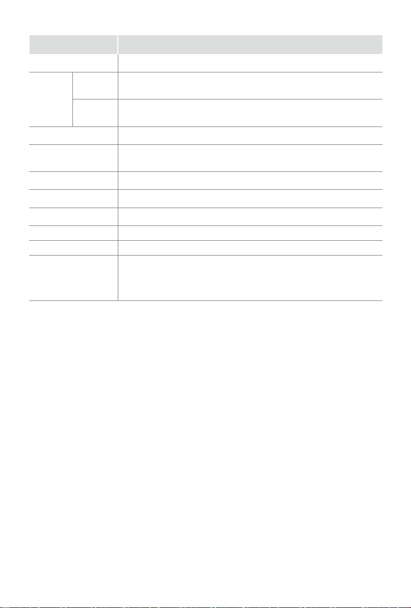
Model 86''
Product name Digital Signage
Size (mm)
(W×H×D)
excluding
handle
including
handle
1926.6×1095.5×64.2
1926.6×1095.5×89.1
Product weight (kg) 38.2
Visual picture
diagonal size (cm)
217
Display resolution 3840×2160
Product power 360W
Sound power 10W+10W
Executive standard Q/0202RSR 615
Power supply 100-240V ~ 50/60Hz
Operating temperature: 0°C~40°C
Environmental
conditions
Operating humidity: 10%~80%RH
Atmospheric pressure: 86kPa~106kPa
35
Page 43
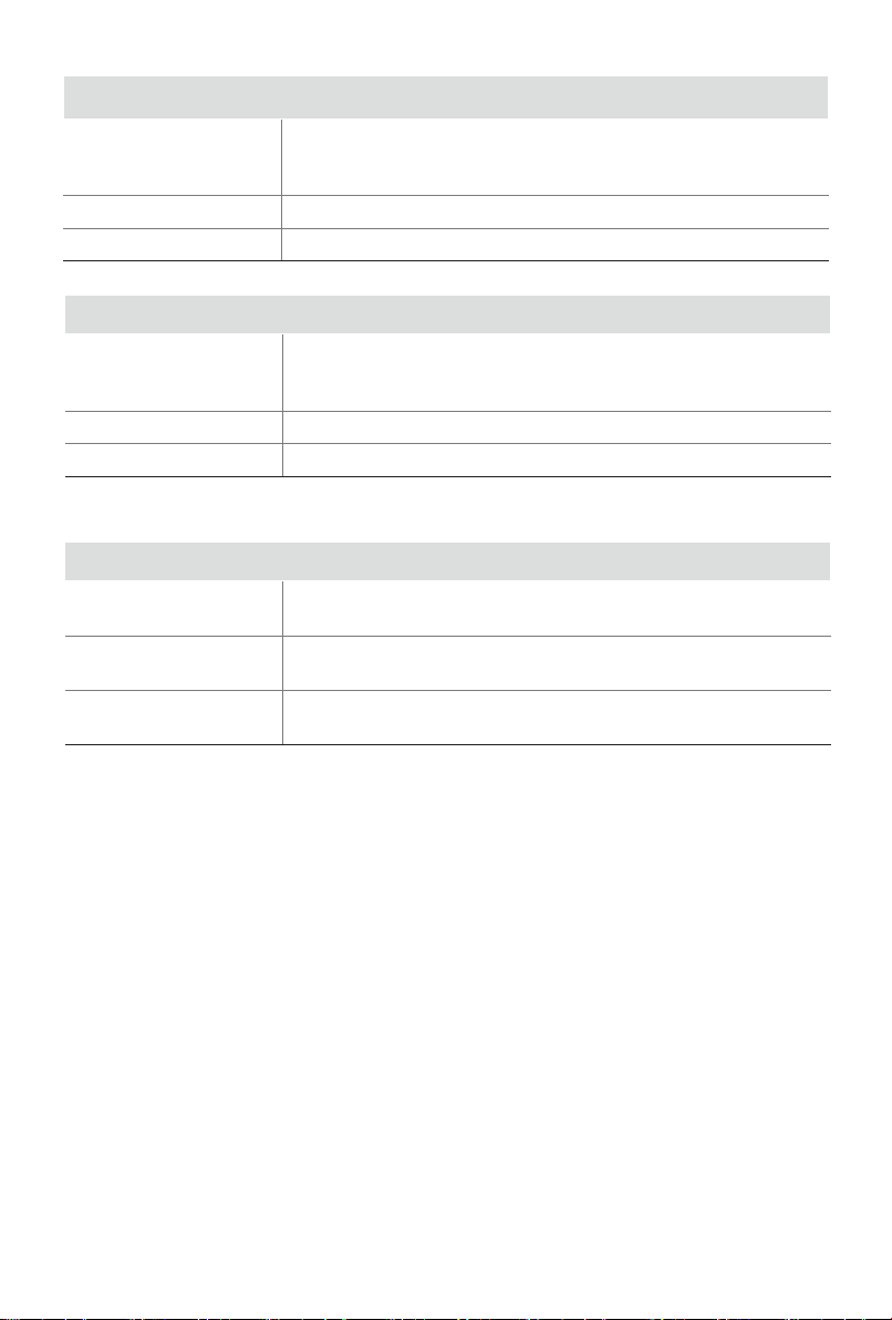
Signal Formats Supported by DP Port
640×480、800×600、1024×768、1280×720
RGB/60Hz
1280×1024、1360×768、1366×768、1600×900
1920×1080、3840×2160
YUV/50Hz 720p、1080i、1080p
YUV/60Hz 720p、1080i、1080p
Signal Formats Supported by HDMI Port
640×480、800×600、1024×768、1280×720
RGB/60Hz
1280×1024、1360×768、1366×768、1440×900
1600×900、1920×1080、3840×2160
YUV/50Hz 576i、576p、720p、1080i、1080p
YUV/60Hz 480i、480p、720p、1080i、1080p
Multimedia Formats Supported by USB Port
Video coding format
Audio coding format
Picture format
VP9 / HEVC / H265 / MPEG1 / MPEG2 / MPEG4 /
SorensomH.263 / H263 / H264 / AVS
MP3 / AVI / ASF / MKA / MKV / 3gpp / 3gp / mp4 / m4a / ⿿v
/ wav / ts / mpg / mpeg
JPEG,BMP,PNG(The limitation of max resolution depends
on DRAM size,up to 15360x8640
、
、
、
、
)
36
 Loading...