

Page 1
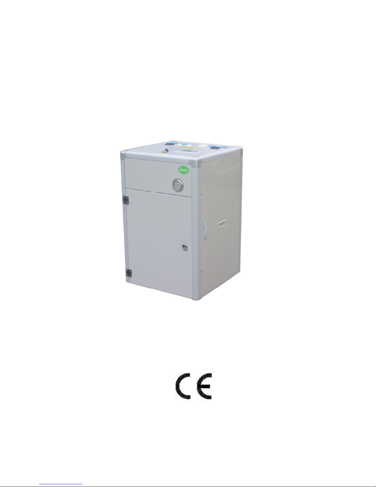
GEOTHERMAL HEAT PUMP
Installation ,Operation &Maintenance Manual VR2002
V.201212
The Installation of this unit is to adhere to all Local
Building Codes and Standards
Page 2

1
Index
Pre-Installation ............................................................................................................. 2
Installation Location and Positioning ........................................................................ 4
Buffer Tank ................................................................................................................... 5
System Overview Vertical Ground Loop System ...................................................... 6
System Overview Horizontal Ground Loop System ................................................. 7
System Overview Ground Water with Intermediate Heat Exchanger System ...... 8
System Overview Floor Heating Only ........................................................................ 9
System Overview Heating ,Cooling & Hot Water ................................................... 11
System Overview Multiple Units in Series Cascade Connection ........................... 15
Installation .................................................................................................................. 17
Electrical Connection ................................................................................................. 19
Controller .................................................................................................................... 31
Commissioning and Adjusting .................................................................................. 39
Warning and alarm .................................................................................................... 42
Trouble shooting ......................................................................................................... 46
Maintenance ............................................................................................................... 47
Dimension ................................................................................................................... 48
Components ................................................................................................................ 50
Pressure drop curve ................................................................................................... 56
Temperature and sensor resistance table ................................................................. 60
Technical specifications ............................................................................................. 63
Page 3
2
Pre-Installation
Important Site Instructions
The installation, commissioning, inspection, maintenance and repairs must only be
carried out by a qualified person.
All electrical wiring must be completed by a licensed electrical contractor in
accordance with the appropriate standards.
The drilling work requires a permit from your local council.
The heating system and heat source must be properly designed and dimensioned
to ensure an efficient operation. It is particularly important to keep water flow
temperatures as low as possible.
The minimum heating water flow rate through the heat pump must be assured in
all operating states of the heating system.
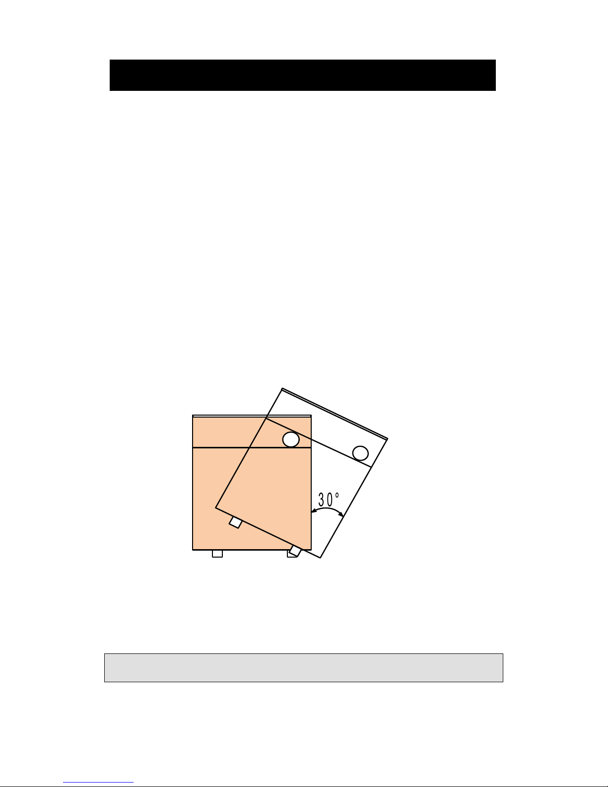
Movement and storage
The unit must not be transported, moved or stored at greater than a 30° angle from the
upright position. Install and store the unit in a dry area. They are not rated for outdoor
use.
Safety
If a refrigerant leak occurs, remove the complete charge using a recovery unit and
store the refrigerant in mobile container.
Note: care is to be taken as the refrigerant can breakdown due to high temperature,
these refrigerants by-products are dangerous.
Once the leak has been repaired recharge the unit with the correct filling weight and
the type found on the unit’s nameplate.
Pre-Installation
Page 4

3
Note: ensure the correct refrigerant gas is used to recharge the unit as an incorrect
gas can cause damage beyond repair to the compressor.
Do not use oxygen to purge lines or to pressurize a unit for any purpose.
Oxygen gas reacts violently with oil, grease and other common substances. Use only
refrigerant or dry nitrogen for testing.
Never exceed the specified maximum operating pressures.
Do not un-weld or flame cut the refrigerant lines including any refrigerant circuit
components until the entire refrigerant (liquid and vapour) has been removed from
unit. Traces of vapour should be displaced with dry nitrogen.
Refrigerant in contact with an open flame will produces toxic gases.
Ensure that the necessary safety protection equipment is available when servicing.
Have the appropriate fire extinguishers for that system.
Do not siphon refrigerant.
Avoid spilling liquid refrigerant onto the skin or splashing it into the eyes. Use safety
goggles. Wash any spills from the skin with soap and water. If liquid refrigerant enters
the eyes, immediately and abundantly flush the eyes with water and consult medical
advice.
Note: Never apply an open flame or live stream to a refrigerant container. This can
dangerously overpressure and cause an explosion.
Pre-Installation
Page 5

4
Installation Location and Positioning
The unit must be installed in a protected area that is free from rain and water
penetration.
The unit must be installed on a solid level surface, preferably on a concrete pad
not connected to the main house slab foundation.
Allowances for good ventilation around the installation must be provided.
In normal operations to prevent condensation collecting on cold pipes the thermal
insulation of any cold components should be to a high level.
The unit will produce noise that is above the minimum 45 decibel rating.
Therefore the unit should be located so that it is well away from bedrooms, offices,
living areas or noise sensitive areas including neighbour’s bedrooms.
There must be suitable distances between the unit and the building to ensure
normal operation and enough room for maintenance requirements.
Installation Location and Positioning
Page 6

5
Buffer Tank
A buffer tank is recommended to ensure a trouble free heat pump operation. A suitable
buffer tank can avoid excessive heat pump cycling (switching on and off).
The buffer tank provides a hydraulic separation from the volume flow in the heat
pump and heating circuits. The volume flow in the heat pump circuit remains constant,
even if the heating circuit volume flow is reduced by thermostatic valves.
If the total of the systems water volume is less than 12L/KW then a buffer tank should
be added to reduce the compressor from ON/OFF cycling. This will prolong the
compressor life span.
When a buffer tank is installed, the heating system will absorb energy from the buffer
tank first. To save energy consumption ,install the indoor pump P1 that is switched on
only when compressor is on. This is by changing EV01 to “1”.
RT sensor should be taken out of the unit and put into buffer tank’s sensor pocket. The
RT sensor is located at lower submerged sensor pocket of the plate heat exchanger.
The RT sensor in the buffer tank will control the tank temperature by starting and
stopping the compressor and pump together as required.
If RT sensor has not been changed to buffer tank’s sensor pocket when EV01 has been
changed to “1”, when the unit reaches its set temperature ,the compressor will stop,
pump P1 will also stop accordingly due to EV01 being set to “1”. When this
occurs ,there is no water circulation between the heat pump and buffer tank. RT will
keep its stopped temperature ,not the buffer tank water temperature. RT then can not
switch on compressor and pump P1 even when buffer tank water is getting cold.
Changing the RT sensor into the buffer tank will avoid this problem.
Buffer Tank
Page 7
6
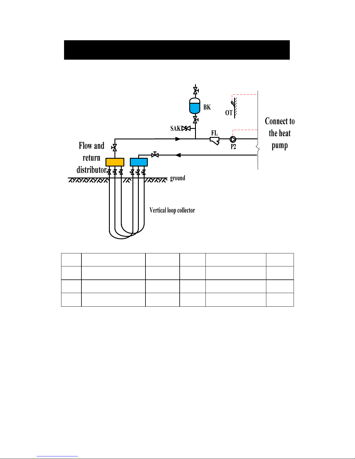
System Overview Vertical Ground Loop System
Name
Description Location Name Description Location
P2
Outdoor side water
pump
External OT
Outdoor temperature
sensor
Internal
SAK
Safety valve External FL Particle filter External
BK
Brine tank/expansion
tank
External
Systems Overview (Outdoor side)
Page 8

7
System Overview Horizontal Ground Loop
System
Name
Description Location Name Description Location
P2
Outdoor side water
pump
External OT
Outdoor temperature
sensor
Internal
SAK
Safety valve External FL Particle filter External
BK
Brine tank/expansion
tank
External
Systems Overview (Outdoor side)
Page 9
8
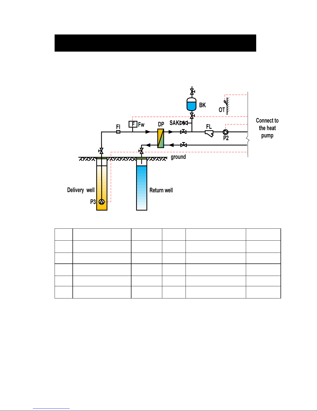
System Overview Ground Water with
Intermediate Heat Exchanger System
Name
Description Location Name Description Location
P2 Outdoor side water pump External OT
Outdoor temperature
sensor
Internal
P3 Ground water pump External FL Particle filter External
BK
Brine tank/expansion
tank
External SAK Safety valve External
FW Water flow switch External FI filter External
DP
Intermediate heat
exchanger
External
Principle of Operation:
An intermediate heat exchanger (DP) should be installed to prevent ground water
damaging or contaminating the unit’s internal heat exchanger. A plate heat exchanger
that is able to be cleaned is recommended for this situation that can be disassembled
for cleaning and repair or any damage plates can be replaced. Anti-freezing
measurement must be adopted to protect the ground water circuit.
Systems Overview (Outdoor side)
Page 10
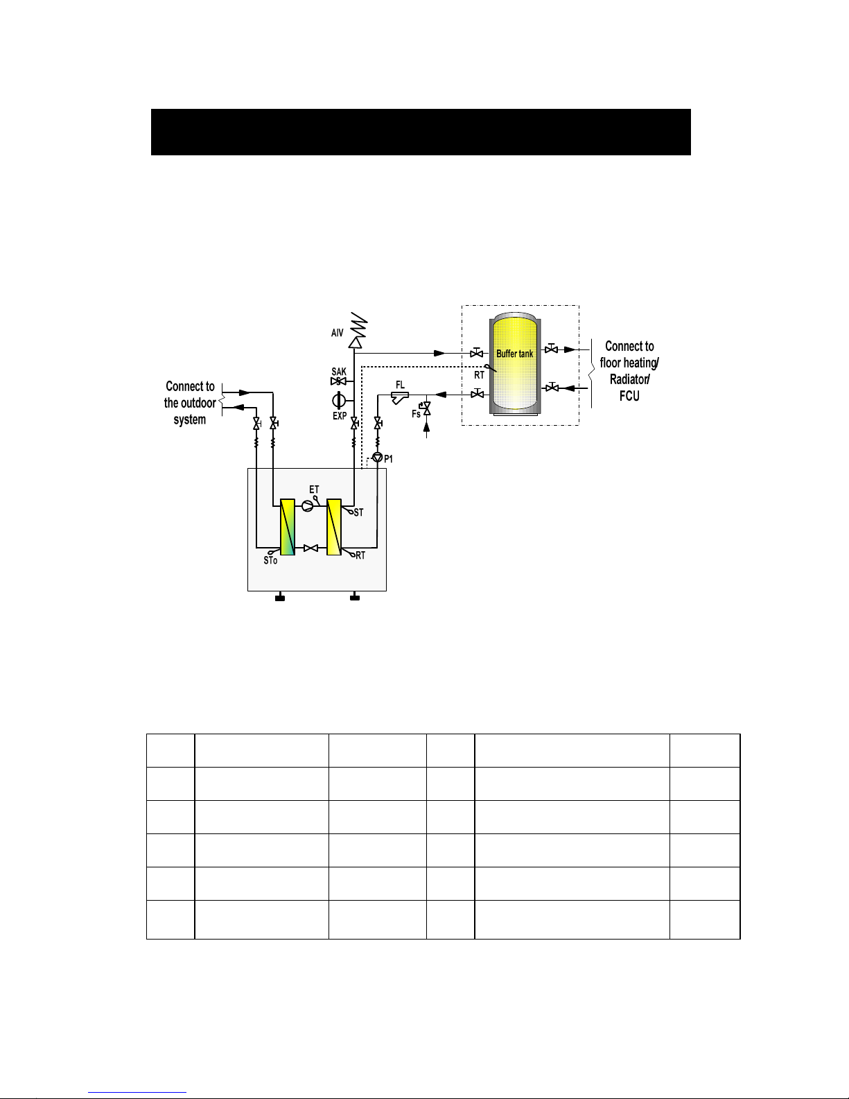
9
System Overview Floor Heating Only
Name
Description Location Name
Description Location
P1
Indoor side water
pump
External RT
Indoor side inlet water
temperature sensor
Internal
EXP
Expansion tank External ST
Indoor side outlet water
temperature sensor
Internal
AIV
Air vent valve External STo
Outdoor side outlet water
temperature sensor
Internal
SAK
Safety valve External ET Exhaust gas temperature sensor Internal
FS
Automatic water
supplement valve
External FL filter External
Systems Overview (Indoor side)
Page 11

10
1. Heating Mode Working Principle:
a. When SF04=0,
When the RT drops below ST02-ST04, the compressor will start to heat until RT
≥
ST02+ST04. Then compressor will stop. The Compressor will start again when RT
≤
ST02-ST04.
b. When SF04=1,
ST02 is replaced by “Set temperature at heating” =ST05+ST06/10 *(ST05-OT).
Refer to page 36 “Heating compensation curve setting” and page 37 “Three curves of
different ST05 setting”
Systems Overview (Indoor side)
Page 12
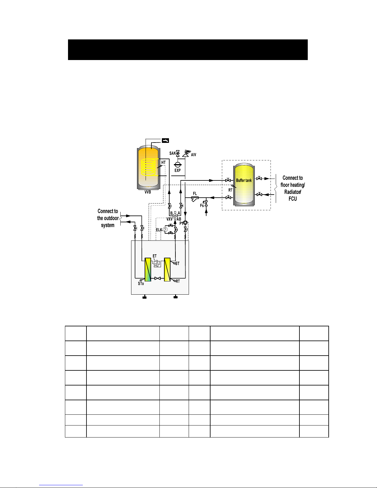
11
System Overview Heating ,Cooling & Hot
Water
(External water pump, three way valve and electric heater)
Name
Description Location Name
Description Location
P1 Indoor side water pump External RT
Indoor side inlet water
temperature sensor
Internal
ELK
Electric heater/boiler External ST
Indoor side outlet water
temperature sensor
Internal
EXP
Expansion tank External STo
Outdoor side outlet water
temperature sensor
Internal
VXV
Three way valve External HT Hot water temperature sensor Internal
FS
Automatic water
supplement valve
External ET Evaporator temperature sensor Internal
SAK
Safety valve External FL Particle filter External
VVB
Hot water cylinder External AIV
Air vent valve External
Systems Overview (Indoor side)
Page 13

12
System Overview Heating ,Cooling & Hot Water
(External water pump, three way valve and electric heater)
1. Heating Mode Working Principle:
On heating mode, Three way valve (VXV) will open AB-A.
1.) When SF04=0:
a. When the RT drops below ST02-ST04, the compressor will start to heat until
RT≥ST02+ST04. Then compressor will stop. The Compressor will start again
when RT<ST02-ST04.
b. When the outdoor temperature meets the conditions of OT≤ST07,
the e
lectric
heater (ELK) will be activated as heating boost. It will stop heating when OT
≥ ST07+ST08.
2.) When SF04=1:
ST02 is replaced by “Set temperature at heating” =ST05+ST06 *(ST05-OT). Refer
to page 36 “Heating compensation curve setting” and page 30 “Three curves of
different ST05 setting”
3.) Cooling Mode Working Principle:
On cooling mode, Three way valve (VXV) will open AB-A.
When the RT≥ST01+ST03, the compressor will start to cool until RT≤
ST01-ST03. Then compressor will stop. The Compressor will start again when
RT≥ST01+ST03.
4.) Hot water production working principle:
On hot water mode, Three way valve (VXV) will open AB-B.
When domestic hot water requirement calls, the three way revert valve (VXV) will
have the priority to revert to the hot water tank (VVB). After the domestic hot water
reach its set temperature ST09, the three way revert valve (VXV) return to its
heating/cooling position. After HT≤ST09 – ST10, three way revert valve (VXV) will
revert to hot water circuit again.
Systems Overview (Indoor side)
Page 14
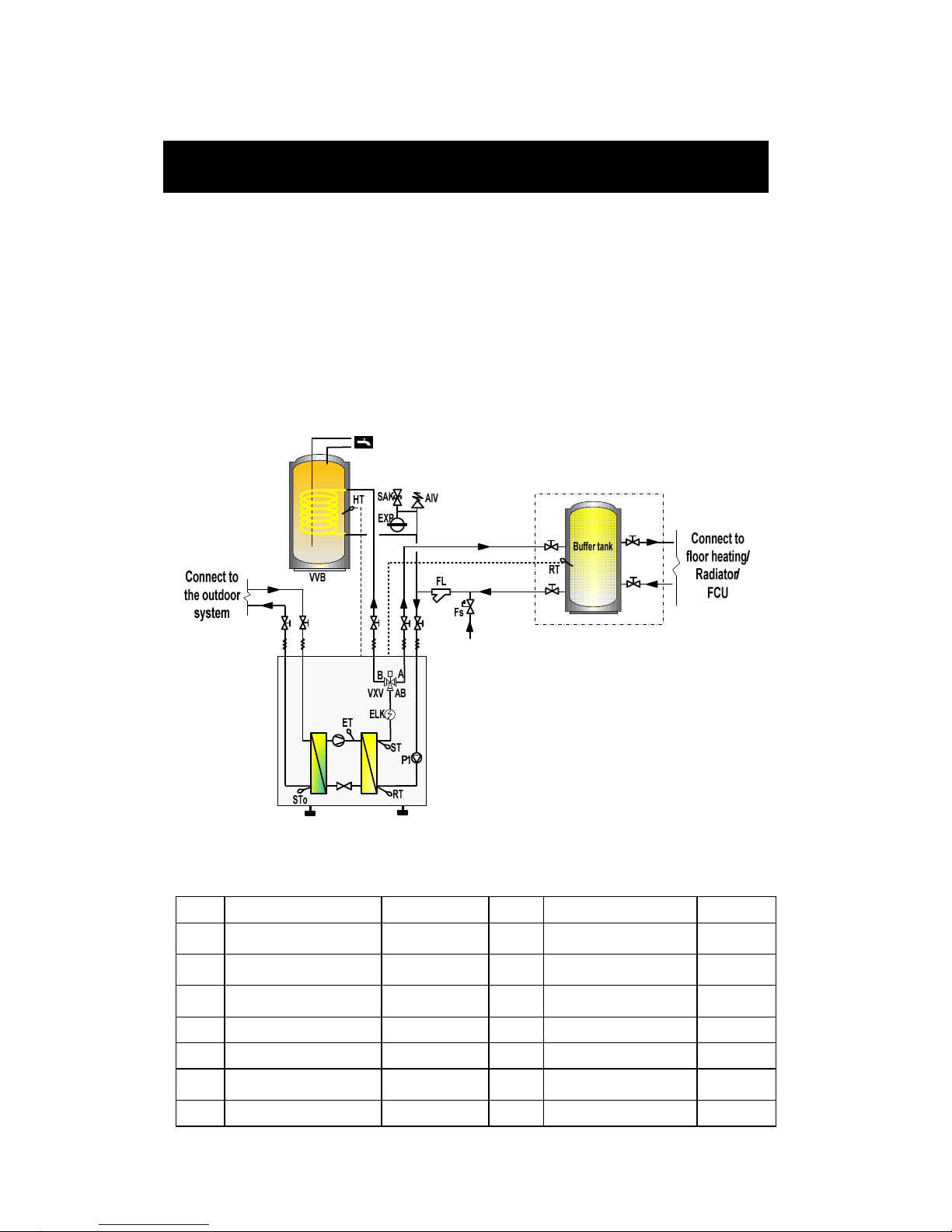
13
System Overview Floor Heating with Hot Water
(Internal water pump, electric heater and three way valve)
Name
Description Location Name
Description Location
P1 Indoor side water pump Internal(Option) RT
Indoor side inlet water
temperature sensor
Internal
EXP
Expansion tank External ST
Indoor side outlet water
temperature sensor
Internal
VXV
Three way valve Internal(Option) STo
Outdoor side outlet water
temperature sensor
Internal
ELK
Electric heater Internal (option) HT Hot water temp. sensor Internal
SAK
Safety valve External ET Exhaust gas temp. sensor Internal
FS
Automatic water
supplement valve
External FL Particle filter External
VVB
Hot water tank External AIV Air vent valve External
Systems Overview (Indoor side)
Page 15

14
System Overview Floor Heating with Hot Water
(Internal water pump ,electric heater and three way valve)
1. Heating Mode Working Principle:
On heating mode, Three way valve (VXV) will open AB-A.
1.) When SF04=0:
a. When the RT drops below ST02-ST04, the compressor will start to heat until
RT≥ST02+ST04. Then compressor will stop. Compressor will start again
when RT≤ST02-ST04.
b. When the outdoor temperature meets the conditions of OT≤ST07,
the e
lectric
heater (ELK) will be activated as heating boost. It will stop heating when OT
≤ ST07+ST08.
2.) When SF04=1:
ST02 is replaced by “Set temperature at heating” =ST05+ST06 *(ST05-OT).
Refer to page 36 “Heating compensation curve setting” and page 37 “Three
curves of different ST05 setting”
2. Hot water production working principle:
On hot water mode, Three way valve (VXV) will open AB-B.
When domestic hot water requirement calls, the three way revert valve (VXV) will
have the priority to revert to the hot water tank (VVB). After the domestic hot water
reach its set temperature ST09, the three way revert valve (VXV) return to its floor
heating position. After HT≤ST09 – ST10, three way revert valve (VXV) will revert
to hot water circuit again.
Important
The coil heat exchanger inside the hot water cylinder VVB should be well selected
to have big enough diameter and heat exchange capacity. Otherwise, heat pump
will have high outlet water temperature protection alarm AL05 frequently
.
..
.
Systems Overview (Indoor side)
Page 16

15
System Overview Multiple Units in Series
Cascade Connection
Name
Description Location Name
Description Location
P1 Indoor side water pump
Internal
(option)
RT
Indoor side inlet water
temperature sensor
Internal
EXP
Expansion tank External ST
Indoor side outlet water
temperature sensor
Internal
SAK
Safety valve External HT Hot water temperature sensor Internal
FS
Automatic water
supplement valve
External STo
Outdoor side outlet water
temperature sensor
Internal
CV Non-return valve External ET Exhaust gas temp. sensor Internal
FL Particle filter External VVB
Hot water cylinder External
AIV
Air vent valve External
Systems Overview (Indoor side)
Page 17

16
System Overview Multiple Units in Series Cascade
Connection
(1) Heating working principle
To set two or more units in parallel operation, set the primary unit to the required
parameters, other units could have 2~5°C difference of ST01,ST02 and ST05 to allow
for energy stage control.
1. When SF04=0:
a). if the RT (inlet water temperature) is lower than ST02-ST04 of the unit, then
the unit will start to heat. The unit with the lower ST02+ST04 will stop first, the
others will stop as well if the RT continues to rise and be over its ST02+ST04.
b). RT will drop when units stop. The unit with the higher ST02-ST04 will start
first again to heat . If this unit can meet the heating capacity then its RT will not
drop any further, only this unit will run as required. If the heating load is bigger
than the capacity of one unit then the RT will continue to drop to below the second
unit ST02-ST04 , the second unit will start increasing the heating capacity.
2. When SF04=1:
ST02 is replaced by “Set temperature at heating” =ST05+ST06 *(ST05-OT).
Refer to page 36 “Heating compensation curve setting” and page 37 “Three curves
of different ST05 setting”
(2) Hot water production working principle:
On hot water mode, Three way valve (VXV) will open AB-B.
When domestic hot water requirement calls, the three way revert valve ( VXV) will
have the priority to revert to the hot water tank (VVB ). After the domestic hot water
reach its set temperature ST09, the three way revert valve ( VXV) return to heating
circuit position. After HT<ST09 – ST10, three way revert valve (VXV) will revert to
hot water circuit again.
Important
The coil heat exchanger inside the hot water cylinder VVB should be well selected to
have big enough diameter and heat exchange capacity. Otherwise, heat pump will have
high outlet water temperature protection alarm AL05 frequently
.
..
.
Systems Overview (Indoor side)
Page 18

17
Installation
Installation must be carried out in accordance with current Standards and Building
Codes.The heat pump does not come fitted with shutoff valves and these must be
fitted outside of the heat pump to facilitate future service.
Important
The pipe work must be flushed before the heat pump is connected so that any
contaminant does not damage the unit’s internal component parts....
Ground Loops:
1. When dimensioning the ground collectors, consideration must be given to the
geothermal location, type of rock, soil structure and the size of the heat pump.
2.
When installing the collector pipe ensure it rises constantly towards the heat pump
to avoid air pockets. If this is not possible install high points to vent the air. The
ground collectors must be free of all air.
3. All brine pipes that enter any rooms must be insulated against condensation. The
expansion tank (BK) must be installed as the highest point in the collector system
and on the incoming pipe before the brine pump. Note: Condensation may drip
from the expansion tank. Position the expansion tank so that it isn’t in the way of
other equipment.
4. When installing the circulation pump for the brine circuit, position the electric
connection at the 12 o’clock position to prevent ingress of condensate.
5. Ensure adequate thermal and sound insulation of all pipes routed through wall
apertures.
6. Thermally insulate pipes on the inside buildings and installed with a vapour seal.
As the temperature of the ground collector system can fall below 0°C, the fluid
must be protected against freezing down to –15°C. The details of the types of
antifreeze used are to be left near the unit for future servicing.
7. Shut-off valves should be installed as close to the heat pump as possible.
8. In the case of a connection to an open ground water system, an intermediate
frost-protected circuit must be provided, due to the risk of dirt and freezing that
could occur in the evaporator, this requires an extra exchanger.
IMPORTANT:
The recommended ground loop pipe length must be adjusted according to the local
conditions. The length of the collector pipe varies depending on the rock/soil
conditions and on the heating system, i.e. radiators or floor heating. Max length per
collector should not exceed 200m.
Installation
Page 19

18
9. Where there is more than one ground loop these must be connected in parallel
with a means of adjusting the flow. For surface soil heat, the pipe should be buried
at a depth of about 1.8 meters and the distance between the hoses should be at
least 1 meter.
10. For bore holes the distance between the holes must be at least 15m.
11. Installation should be inspected before it is commissioned. The inspection must be
carried out by a suitably qualified person and should be documented. The above
applies to closed loop heating systems as well. If the heat pump is replaced the
installation must be re-inspected again.
12. After filling the brine ,check circuit pressure. The pressure should be approx 2 bar.
Minimum system pressure 1 bar, Max pressure should not be over 3 bar.
Pipe Connections (Indoor Side):
1. Pipe connections for the indoor side are located on the top of the unit.
2. Ensure all required safety devices, shut-off valves (as close to the heat pump as
possible) and particle filter are fitted.The safety valve must have a maximum 3
bar opening pressure and be installed on the water outlet.
3. An expansion vessel that is the correct size for the system must be installed.
Ensure that the diaphragms and seals of the expansion vessel including any safety
valves are suitable for the heat transfer medium.
4. The entire length of the overflow water pipe from the safety valves must be
inclined to prevent water pockets and must also be frost proof if required.
5. Thoroughly flush the heating system.
6. Carry out a leak test.
7. Operating pressure: 2 bar. Max pressure must not be over 3 bar.
Installation
IMPORTANT:
When connecting to a system with thermostats on all radiators a bypass valve
must be fitted, or some of the thermostats must be removed to ensure sufficient
flow through the heat pump.
Page 20
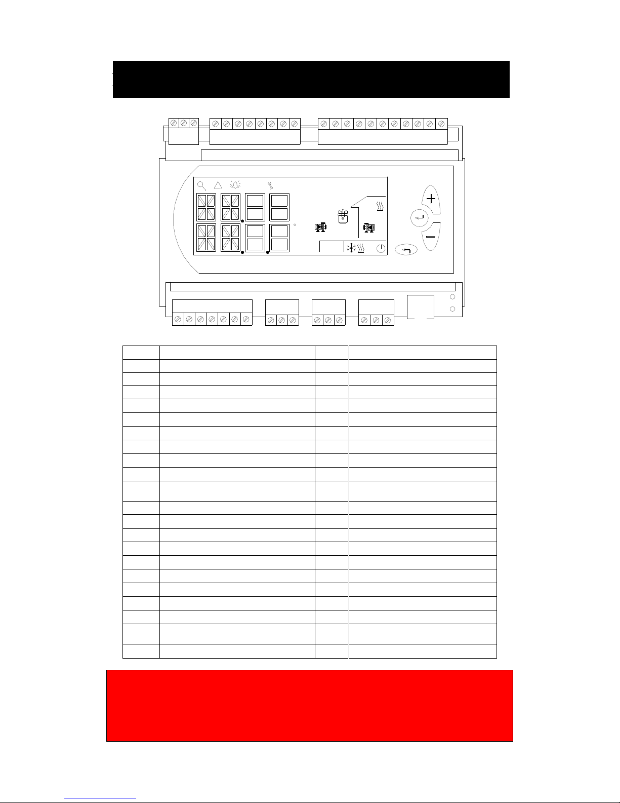
19
Electrical Connection
Q13 Q14
Q34Q24
Q44
Q54
Q64
Q23 Q74 Q84 Y1
G0 Y2
A+ B-
GND
RJ45
G0
PE
D1 M D3D2 M MD4 D5 X1 G ND X3X2 X4 X5GND GND
+5V
X6 +24V
RS485
!
C
G
SIEMENS
RWR470.10
Terminal Assigments Terminal Assignments
G Power supply AC/DC 24 V Q13 Supply 1 (AC 24 V …230 V)
G0 Power supply ground Q14 Compressor 1
PE Saftey ground Q24 Compressor 2
Q34 Indoor water pump
X1 Inlet water temperature of indoor side Q44 Outdoor water pump
X2 Outlet water temperature of indoor side Q54 4-way valve
X3 Outdoor ambient temperature Q64 Electric heater or boiler
X4 Hot water temperature
X5 Outlet water temperature of outdoor side Q23 Supply 2 (AC 24 V …230 V)
X6
Exhaust gas temperature/return gas
temperature
Q74 Hot water pump or revert valve
GND Common reference point for analog input Q84 Alarm
+5 V DC 5 V power output for active sensor Y1 Analog output 2, 0...10 V
+24 V DC 24 V power output for active sensor GND Common reference point
Y2 Analog output 2, 0...10 V
D1 Water flow switch
D2 Low pressure switch A+ A+ connector for RS485
D3 high pressure switch B- B- connector for RS485
D4 Air conditioner switch GND Optional for RS485 communication
D5 Hot water switch RJ45
Service interface for parameters
uploading and downloading
M Common reference point for digital input
Warning:
Electrical connections and servicing must be carried out under the supervision of a
qualified electrician....Electrical installation and wiring must be carried out in
accordance with Local Standards....
Electrical Connection
Page 21

20
Power Connection:
Before connecting the power supply please confirm the unit suits the power supply as
unit nameplate.
Breaker protection must be installed according to the max value stated in the
nameplate attached to the unit inside of front panel.
The equipment must be installed via an isolator switch with a minimum breaking
gap of 3 mm.
Disconnect the heat pump before insulation testing the house wiring.
The unit may be single or three phase, the power supply must conform to the
specification on the unit’s nameplate. The supply voltage must be within the range
specified in the electrical data table. For wiring connection, refer to the electric
wiring diagram on the inside panel of the unit.
When the building is equipped with an earth-fault breaker the heat pump should
be equipped with a separated one.
WARNING:
Disconnect the main power supply switch before servicing the system or handling
any internal parts of the unit.
In case of any major malfunction turn the unit off, disconnect the mains power
supply and contact a qualified service engineer.
Electrical Connection
Page 22
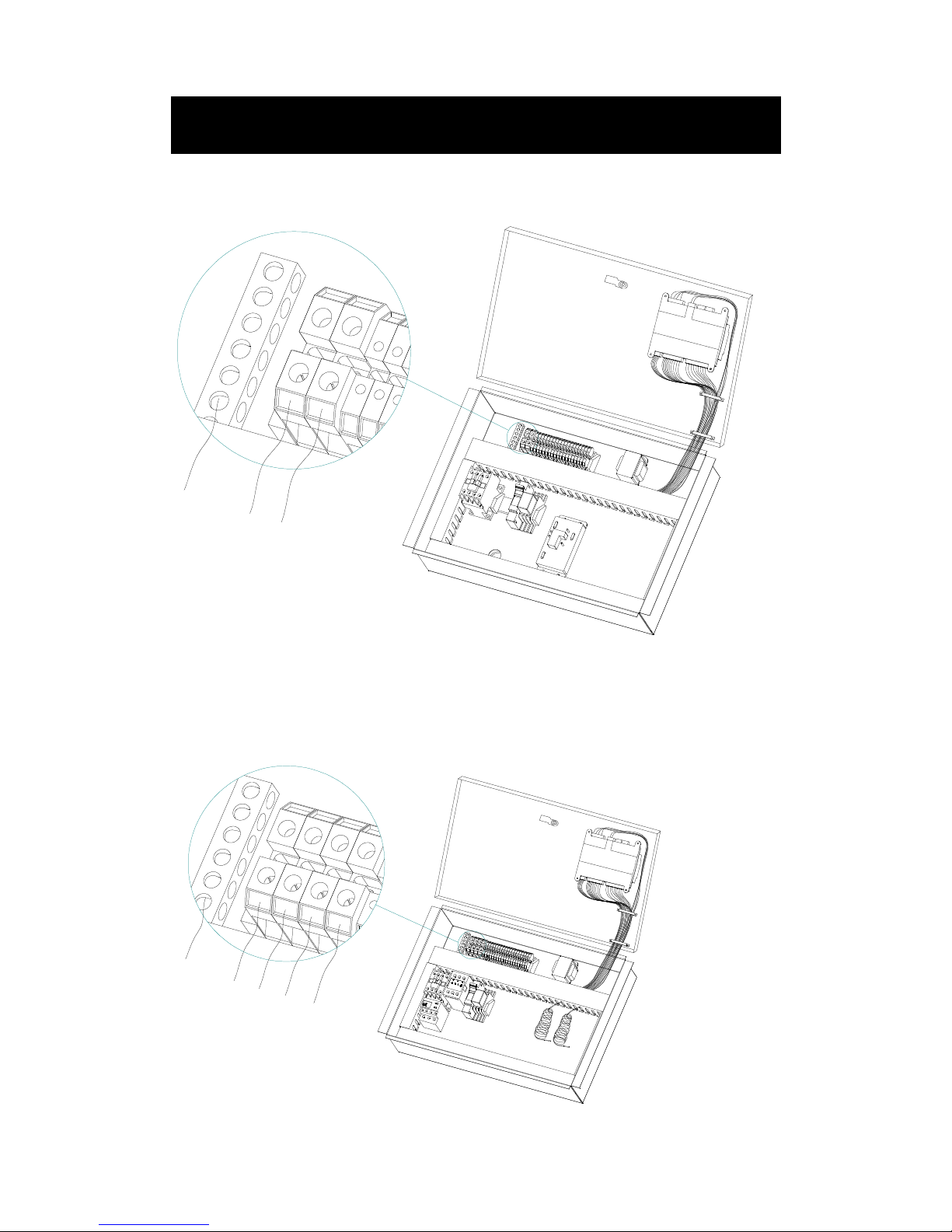
21
Single phase connection port on connection terminal
PE
N
L
Triple phase connection port on connection terminal:
PE
L1
L2
L3
N
Electrical Connection
Page 23
22
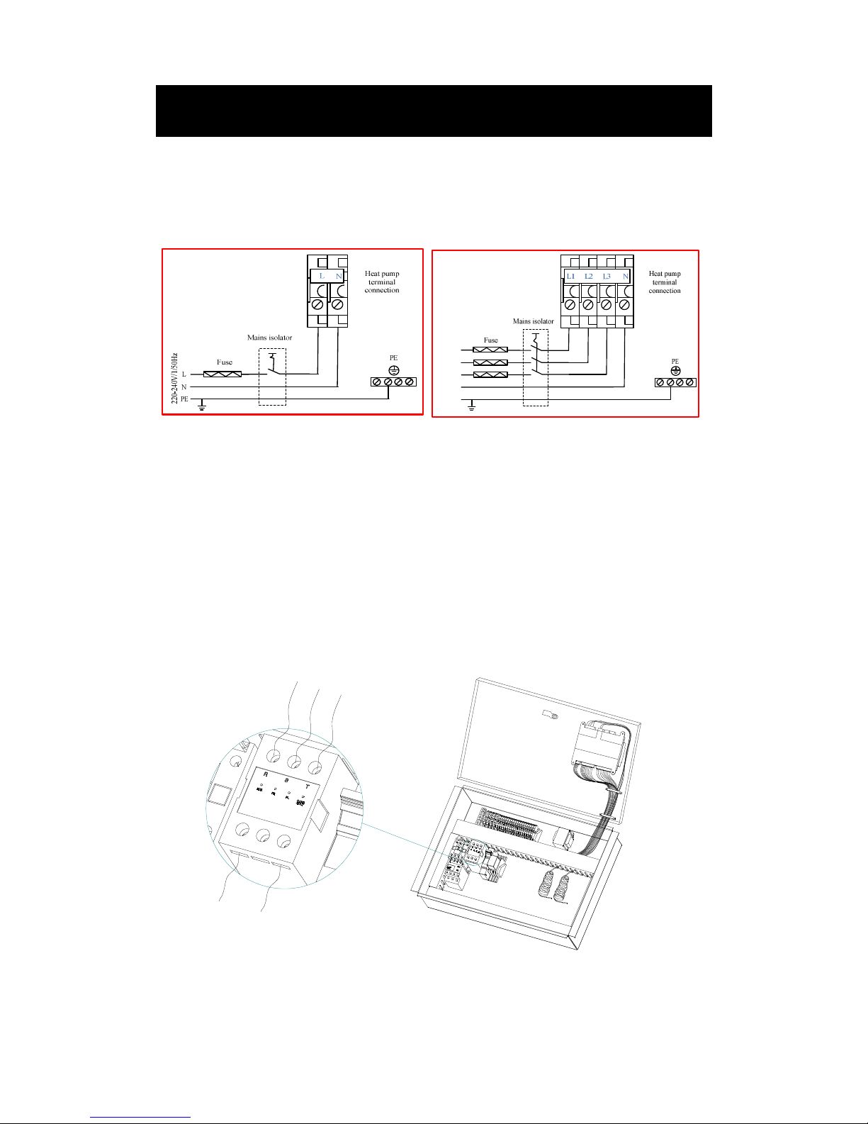
Mains Connection Diagram
Single phase: Triple phase:
Phase relay:
There is a phase relay for three phase units. After powering the unit up for the first
time check the indication lights on the device.
“Normal” green light on means that phase connection is correct
“PR” red light on means that phase connection is in reversal.
“PL” red light on means that there is a loss of one or more phases.
“O UVR-VOLT” red light on means that power supply voltage is too high/low.
L3
L2
L1
L
N
Electrical Connection
380-415V/3/50Hz
Page 24
23
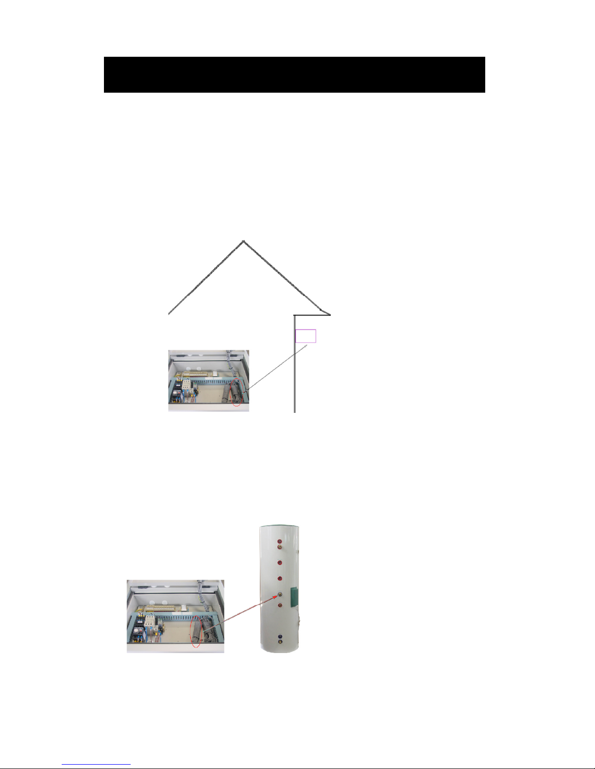
Outdoor Ambient Temperature Sensor:
The outdoor temperature sensor (OT) is a standard part placed inside the electric box.
One terminal is connected with the PC board X3 and GND, its probe must be installed
outdoors. It should be mounted on a wall that has the mean outdoor temperature
which can accurately measure the outdoor temperature and not to be exposed the rain,
sun and snow.
If the outdoor ambient temperature sensor cable runs close to power cables a shielded
cable should be used. If a conduit is used, it should be sealed to avoid condensation in
the outdoor temperature sensor probe.
Temperature sensor for hot water:
The 6m long hot water sensor (HT) is connected to terminal positions X4 and GND
on the main board, its probe must be put into hot water cylinder temperature sensor
probe inlet pocket if required.
Electrical Connection
Page 25
24
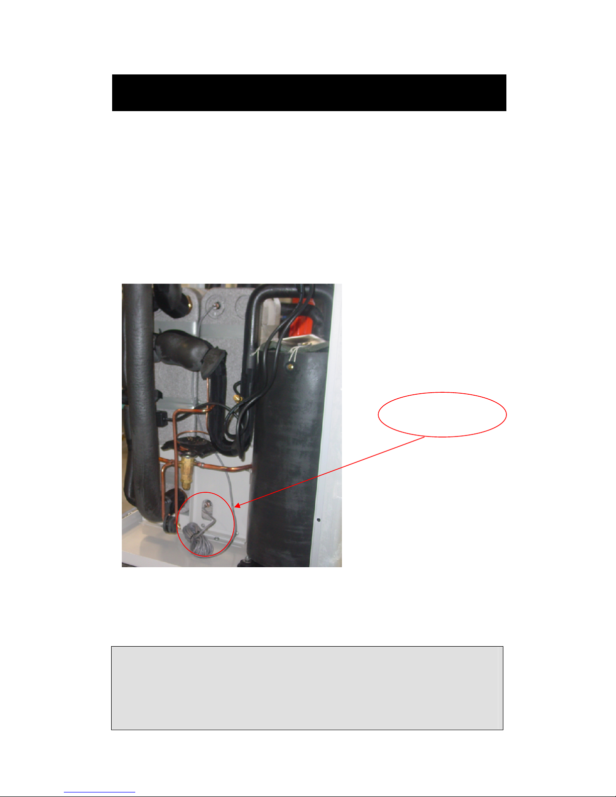
Indoor Side Inlet Water Temperature Sensor:
The indoor side inlet water sensor (RT) from factory is placed in the submerged
pocket of the plate heat exchanger.
If a buffer tank is installed, the RT sensor can be moved to the buffer tank temperature
sensor inlet pocket and EV01 parameter value can be set to “1”. This stops the pump
running when compressor is OFF.
If the RT sensor can not be moved to the buffer tank temperature sensor inlet, the
EV01 parameter value must be set to “0” (factory default setting). This allows the
pump to continue to run so RT measured the same as butter tank water temperature.
6m long RT sensor
Important:
All temperature sensor must be separated (min 200 mm) from high voltage
power cables to avoid interference which will cause measured temperature
fluctuating and the heat pump may operate incorrectly.
Electrical Connection
Page 26
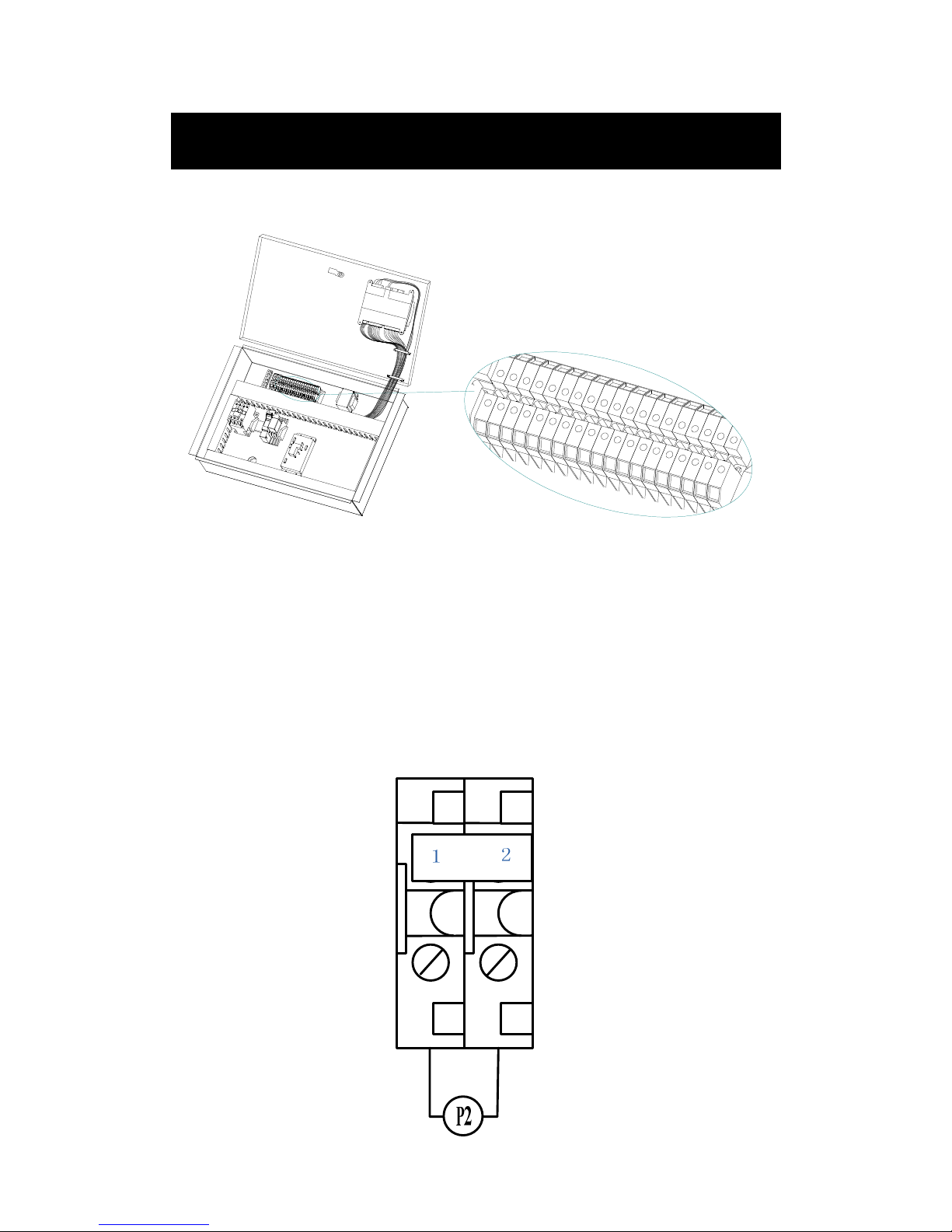
25
Connection Port on Connection Terminal:
C
4
C
3
C
2
C
1
B
2
B
1
A
2
A
1
1
1
1
0
9
8
7
6
5
4
3
2
1
Outdoor Side Water Pump:
Outdoor side water pump is connected to terminal port (1-2). If the water pump
current is over 2A, an A/C contactor must be used to activate the water pump.
Electrical Connection
Page 27
26
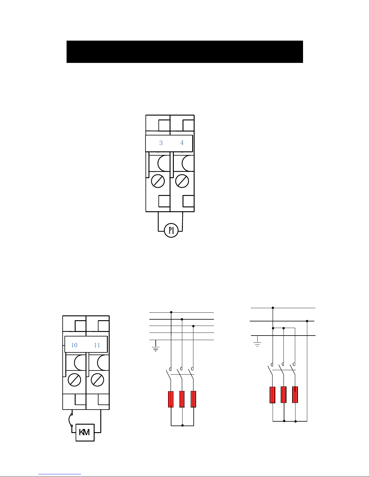
Indoor Side Water Pump:
Indoor side water pump is connected to terminal port (3-4). If the water pump current
is over 2A, an A/C contactor must be used to activate the water pump.
Electric Heater:
Electric heater is connected to terminal port (10-11). An A/C contactor must be used
to activate the electric heater. A thermostat T should be attached on the outer container
of heater to prevent heater from overheating.
Electrical Connection
KM2
N
L1
PE
ELK
L2
L3
10 11
K M
K M K M
K M 2222
T
KM2
N
L
PE
ELK
(Triple phase)
(Single phase)
Page 28
27
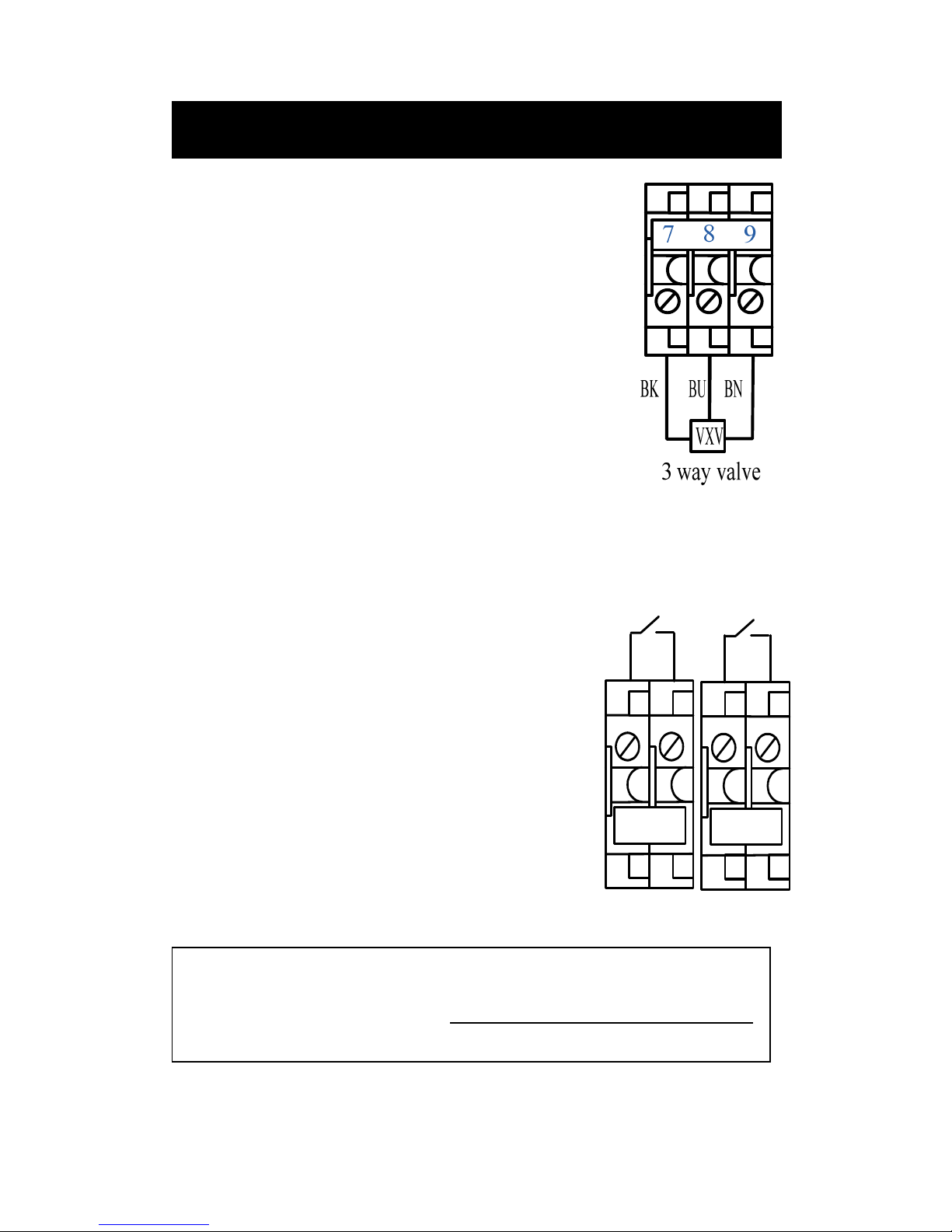
Hot Water Pump or Three Way Valve:
If the indoor side water pump is for both heating and
domestic hot water circulation, set SF10=0, connect a 3
way valve to terminal (7-8-9)
If another pump is used for the domestic hot water circuit,
set SF10=1, connect the hot water pump to terminal (8-9).
Water Flow Switch:
If water flow switch of indoor/outdoor side is not
assembled in the factory, it has to be installed at
site and connected to connection ports C1-C2 C3-C4.
It is used to check if the water flowing is sufficient
or not in the system. If all water flow switches
work normally and the water is flowing, then the
compressor will start, otherwise the compressor is
prohibited to start.
Electrical Connection
C3 C4
C2
C1
Outdoor flow
switch
Indoor flow
switch
Note
This is a potential free input contact only. DO NOT PUT 230VAC INTO THIS CONTACT
Page 29
28
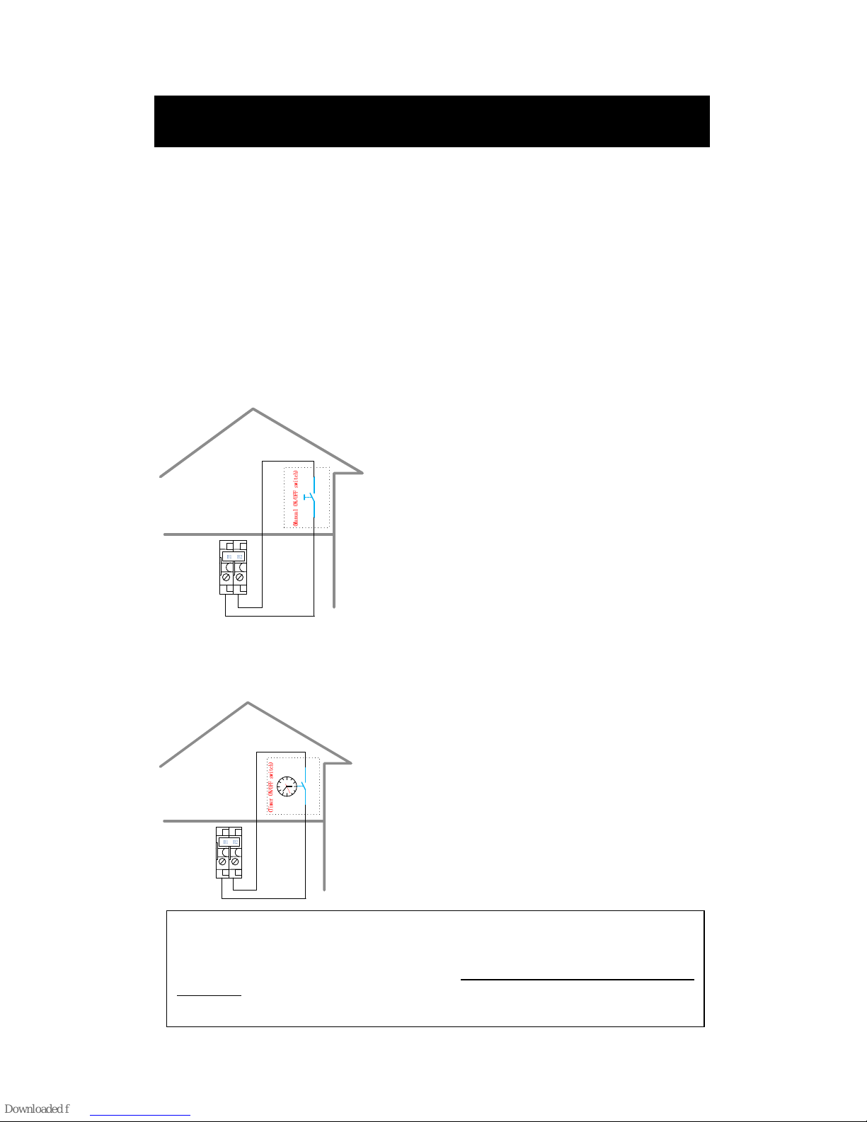
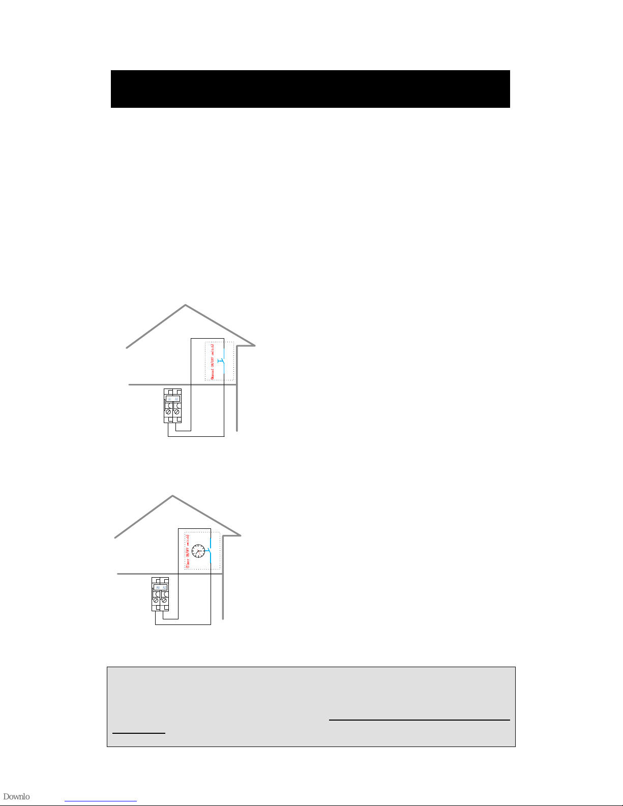
A/C Switch:
The unit’s A/C ON/OFF cannot be operated by any button on the controller.
When the A/C switch B1-B2 is bridged, the unit’s heating /cooling function
is activated. An external signal like a timer or thermostat, etc could be
connected to B1-B2 to activate or deactivate the unit’s heating /cooling
function. This external signal must be voltage free.
Case 1 : Install a manual switch inside the house to switch on/off heating/cooling.
Case 2: Install a timer switch inside the house to switch on/off heating/cooling
automatically in due time.
Electrical Connection
Note
This is a potential free input contact only. DO NOT PUT 230VAC INTO THIS
CONTACT
B1 B2
B1 B2
Page 30
29
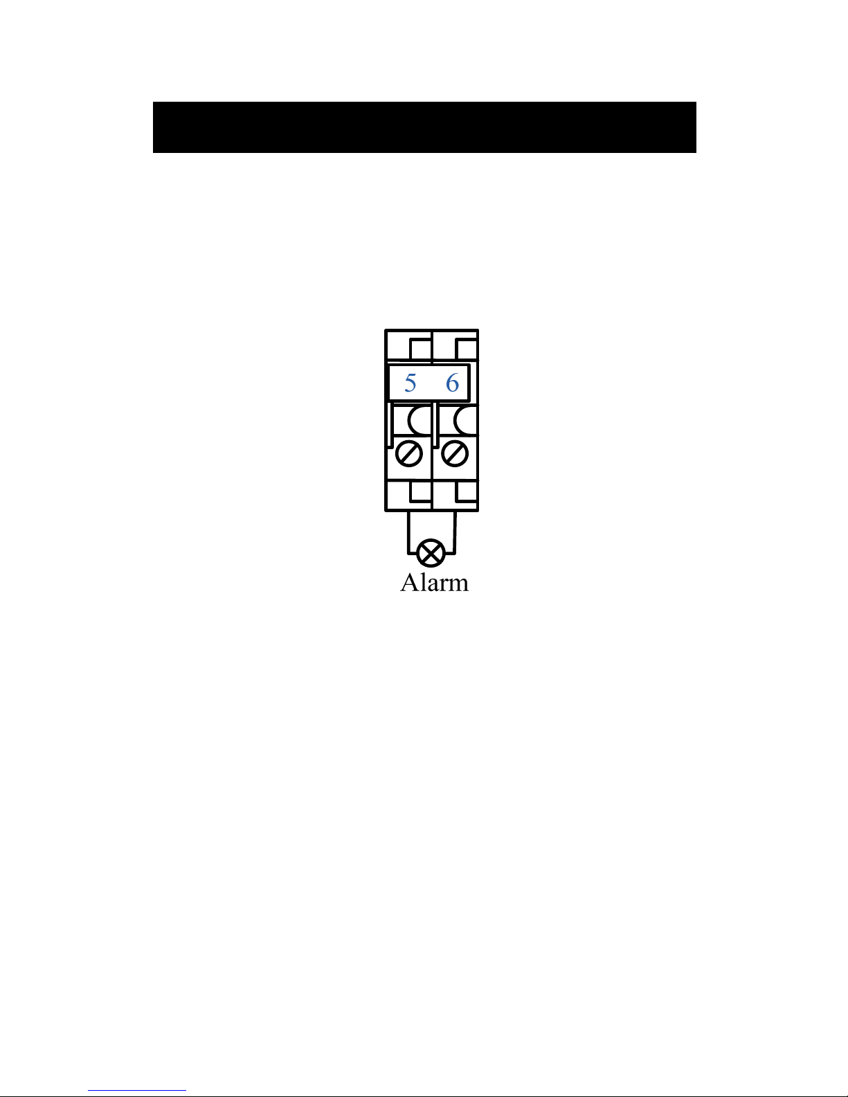
Hot Water Switch:
The unit’s hot water ON/OFF cannot be operated by any button on the
controller.
When hot water switch A1-A2 is bridged, the unit’s hot water function is
activated. An external signal like a timer or thermostat, etc could be
connected to A1-A2 to activate or deactivate the unit’s hot water function.
This external signal must be voltage free.
Case 1 : Install a manual switch inside the house to switch on/off hot water production
Case 2: Install a timer switch inside the house to switch on/off hot water production
automatically in due time.
Note
This is a potential free input contact only. DO NOT PUT 230VAC INTO THIS
CONTACT
Electrical Connection
A1 A2
Page 31
30
Alarm Unit’s Output:
When any alarm occurs Terminal port (5-6) will have a 230V output. It
could be connected to an alarm unit (such as indication lighter, alarm bell
etc).
Electrical Connection
Page 32
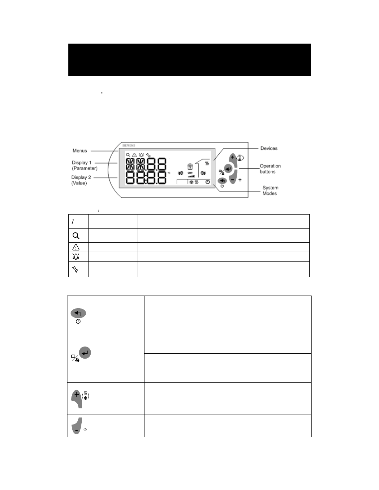
Controller Display (Display window & button area)
Display Area:
In normal working mode: display 1 shows a parameter code, display 2 shows this code
temperature value.
In parameter setting mode: display 1 shows parameter code, display 2 shows this parameter
value.
Menus area:
Icon Meaning Function
Query/view Actual values of all temperature
Warning Existence of warning, and the latest 10 warnings
Alarm Existence of alarm and the latest 20 alarms
Parameters Set parameters and values (see also Menu Tree)
Operating buttons
Button Name Operation
<Esc>
In Menu /parameter setting mode, press it to return to the
previous menu level, or to cancel the value entered
<Enter>
Press down it for more than 2 seconds and release it to enter the
Menu mode when unit is at stop mode (both A/C and hot water
switch are OFF)
In Menu/parameter setting mode, press it to confirm the selected
menu level, or the value entered
Press it to acknowledge/reset warnings and alarms
<Plus>
Press it for 2 seconds to activate the System Mode in stop mode
Or, press it to select the menu level, or to increase the value in
Menu/parameter setting mode
<Minus>
Press it to select the menu level, or to decrease the value in
Menu/parameter setting mode
Controller
Page 33
32
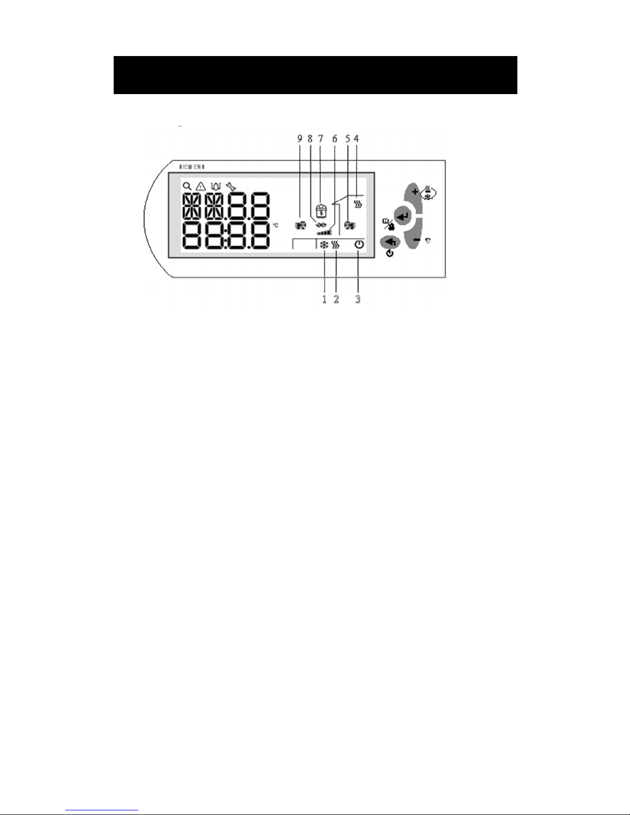
Symbol explanation
1、Cooling mode
2、Heating mode
3、Power
4、Hot water mode
5、Indoor side water pump
6、Compressor energy grade
7、Compressor
8、Water flow switch (light on represents the water flow switch alarm)
9、Outdoor side water pump
Controller
Page 34
33
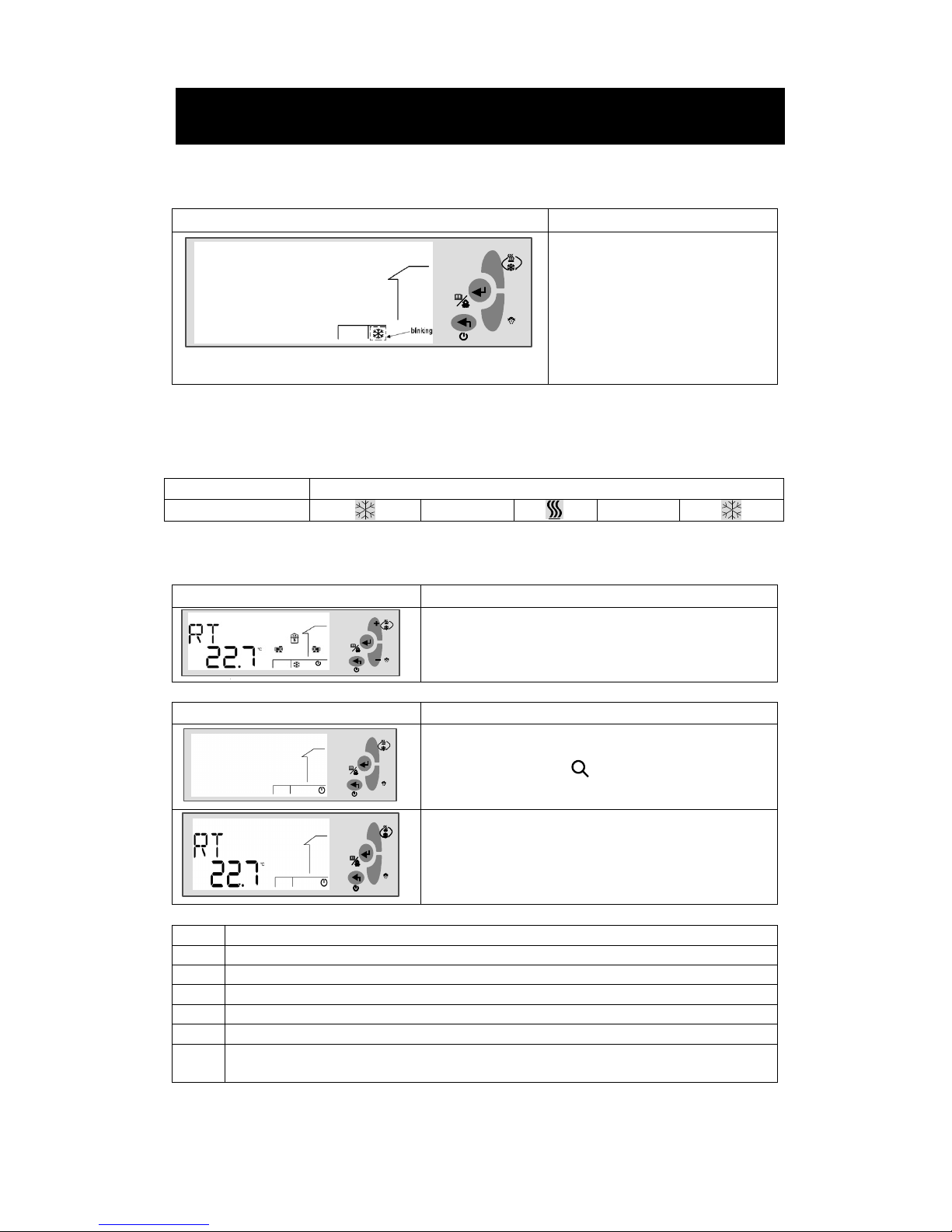
Selection of System Modes
Display Procedures
.
+
-
In the stop mode (A/C switch and
hot water switch are OFF), press the
<Plus> button for 2 seconds, and
release it to activate the selection of
system mode. The current system
mode will start flashing.
Press <Plus> or <Minus> to select
the desired system mode, and then
press<Enter > to confirm.
If the current system is heating only (when SF01=2) or cooling only (when SF01=0), the selection of
system modes is disable.
If the current system is heating & cooling (when SF01=1), the full sequence of selecting the system
modes will be as follows.
Activity Sequence
Press <Plus>
Viewing Temperature
Display Procedures
In normal working mode, press <plus> or <minus>to read
the temperature.
Display Procedures
.
+
-
In stop mode, press the <Enter> button for 2 seconds and
release it to enter the Menu mode.
By default, the Query icon is blinking, waiting for
further instructions.
.
+
-
Press the <Enter> button to enter the query mode.
Press <plus> or <minus>to view the temperature.
Code
Description
RT Inlet water temperature of indoor side
ST Outlet water temperature of indoor side
OT Outdoor ambient temperature
HT Hot water temperature
STo Outlet water temperature of outdoor side
ET Exhaust gas temperature (heating only unit)/Evaporator temperature (heating & cooling
unit)
Controller
Page 35
34
Changing Set Points
Display Procedures
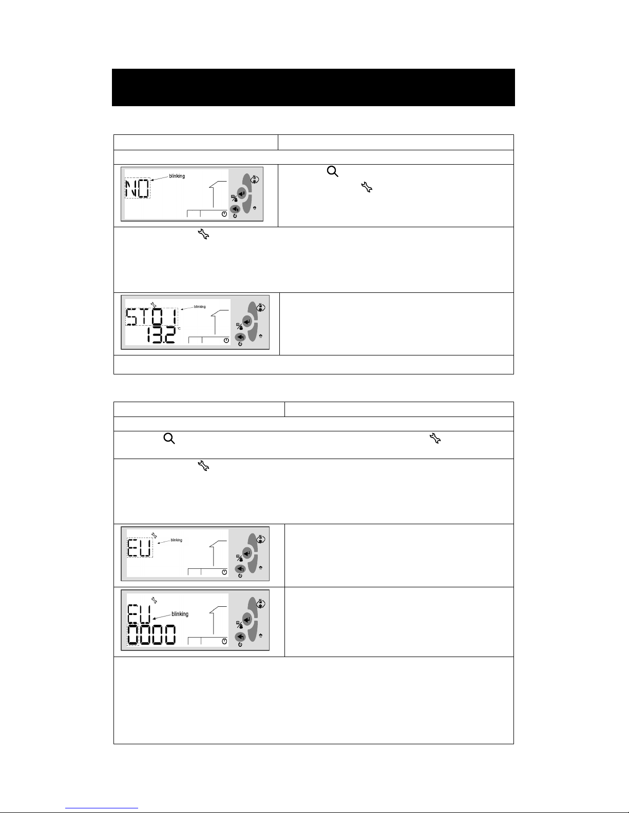
In stop mode, press <Enter> for 2 seconds and release it to activate the Menu mode.
.
+
-
When the icon is blinking, press <Plus> or <Minus>
to navigate to the menu, and then press <Enter> to
proceed.
Contents under the Parameter Menu may vary with the privilege right of the user.
• For end users, select “NO,” and press <Enter > to proceed.
• For service men and factory users, select “EU” or ”ID”, and press <Enter> to input the 4-digit
password .
.
+
-
For end users, parameters in the “ST” group will by
default be displayed.
Or, continuously press <Esc> to exit out of the current level and back to the desired menu level.
Accessing the Parameter Menu
Display Procedures
In Stop mode, press the <Enter> for 2 seconds and release it to activate the Menu mode.
When the icon is blinking, press <Plus> or <Minus> to navigate to the menu, and then
press <Enter> to proceed.
Contents under the menu may vary with the privilege right of the user.
• For end users, select “NO” and press <Enter > to proceed.
• For service men and factory users, select “EU” or “ID” and press <Enter>. Input the 4-digit
password when the following screen is displayed
.
+
-
Press <Enter> to confirm and continue to input the
password.
.
+
-
Password is required for the service man (EU) and
factory users (ID).
To input password, follow the instructions below:
• When the digit is blinking, press <Plus>/<Minus> to select the value. Then, press <Enter> to
confirm, and proceed to the next digit.
• Or, press <Esc> at any time to cancel the input and return to the previous blinking digit.
• Repeat steps above to input other three numbers.
• After inputting the password, press <Enter> to confirm, and proceed to the setting parameter
values.
Controller
Page 36
35
Adjusting Parameter Values
Display Procedures
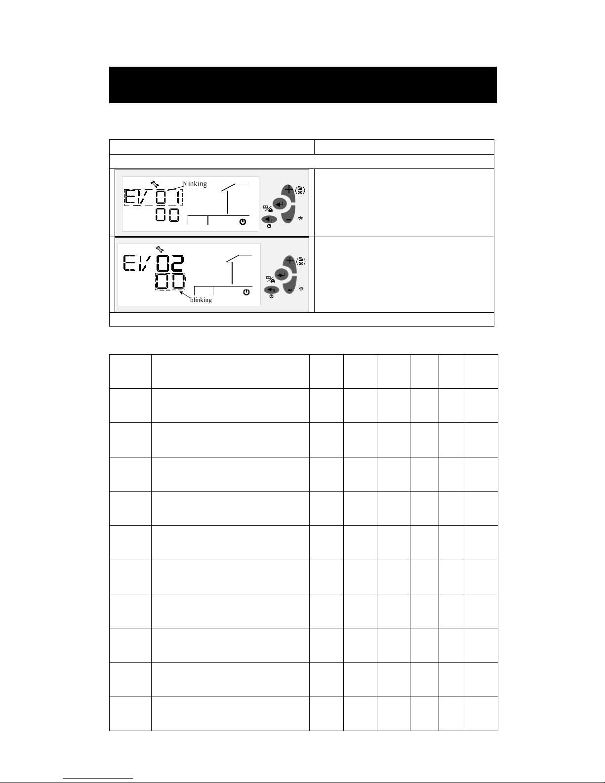
After inputting password and enter into the parameter setting mode.
Press <Plus> or <Minus> to select the
parameter code, and press <Enter> to
confirm.
The default value of the parameter will start
flashing, allowing you to make a change.
Press <Plus> or <Minus> to increase or
decrease the value, and press <Enter> to
confirm.
Continuously press <Esc> to exit out of the current level and back to the desired menu level.
User Settings
Parameter
Descriptions
Default
Min. Max. Unit Res
Privilege
ST01
Setting temperature at cooling mode
(End User)
12 ST11 ST12 ºC 0.1 0
ST02
Setting temperature at heating mode
(End User)
40 ST13 ST14 ºC 0.1 0
ST03
Setting temperature difference at
cooling mode
1 0 10 ºC 0.1 0
ST04
Setting temperature difference at
Heating mode
1 0 10 ºC 0.1 0
ST05
Setting temperature at heating for
compensation function
20 0 30 ºC 0.1 0
ST06
Compensation factor for heating
compensation function
6 0 30 - 0.1 0
ST07
Outdoor temperature to start the boiler
or electric heater
0 -10 20 ºC 0.1 0
ST08
Boiler or electric heater stop outdoor
temperature difference
5 1 20 ºC 0.1 0
ST09 Hot water temperature 50 ST15 ST16 ºC 0.1 0
ST10 Hot water temperature difference 3 1 10 ºC 0.1 0
Controller
Page 37

36
Heating Compensation Curve Setting
The control temperature for the heating mode has two methods: fixed and changeable
temperatures.
1. The fixed temperature is a fixed value and is directly set by the end user from the
set area.
2. The changeable temperature is determined by values of ST05, ST06 and the actual
outdoor temperature measured by the OT sensor probe.
This function is selected by SF04:
When SF04=0, it is fixed temperature;
When SF04=1, it is changeable temperature.
When SF04=0, the set temperature for heating is ST02.
When SF04=1, the set temperature for heating will be controlled by ambient
temperature (OT), ST05 and ST06 according to the following formula:
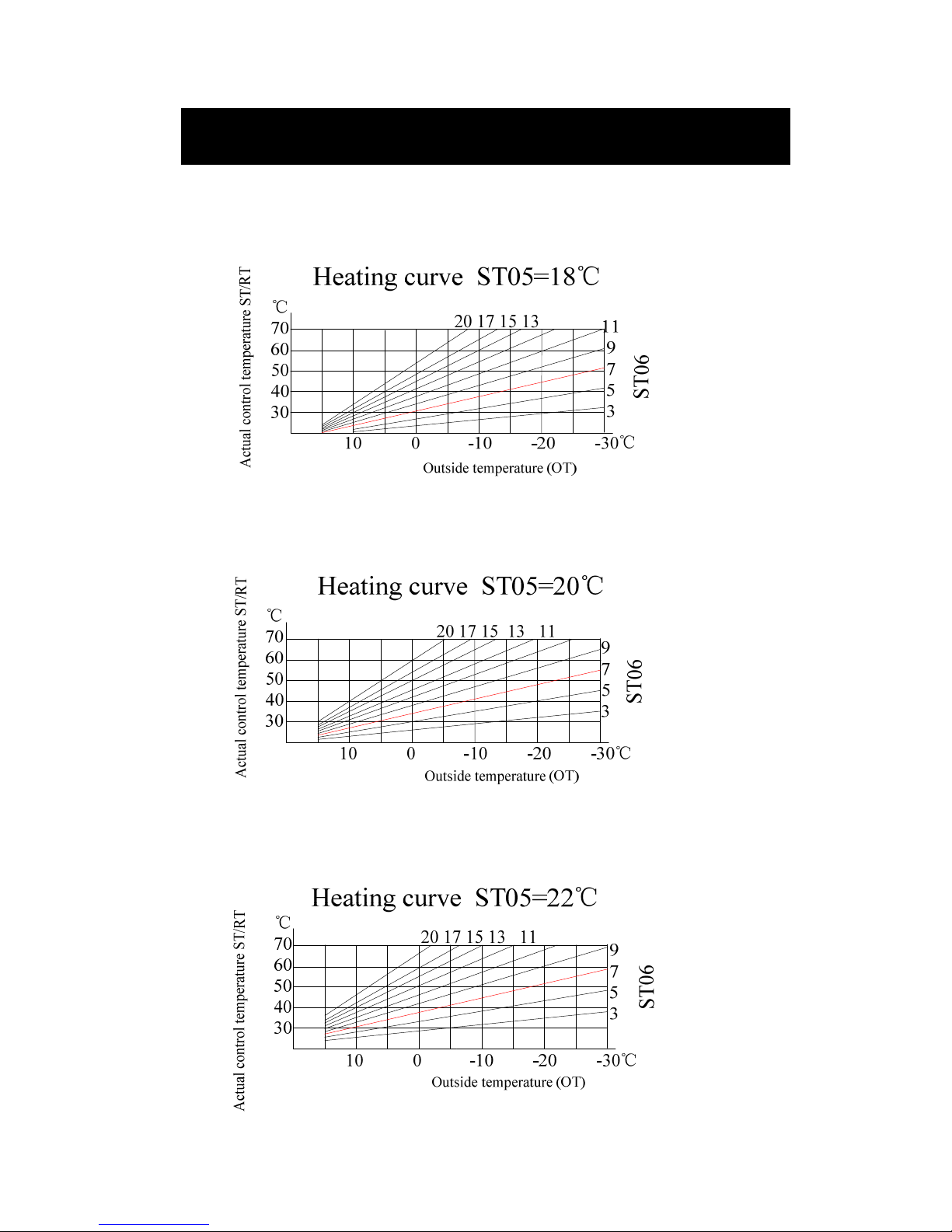
Set temperature at heating =ST05+ST06 /10*(ST05-OT).
1. ST05 is indoor temperature that the user feel comfortable
2. ST06 is the heating compensation coefficient curve factor you select for the
heat pump to work with. Increasing ST06 will increase compensation
temperature and RT will increase relatively.
3. OT is the outside temperature.
4. The calculated temperature can be used for the control reference, but the
maximum data will not exceed ST14.
For example:
1. Set the heating compensation coefficient ST06 to 7,
2. When outdoor temperature is 0°C, the control temperature is :
ST05+ST06 /10*(ST05-OT)=20+7/10*(20-0)=34°C;
3. When outdoor temperature is -10°C, the control temperature is :
ST05+ST06 /10*(ST05-OT)=20+7/10*(20-(-10))= 41°C;
4. When outdoor temperature is –20°C, the control temperature is :
ST05+ST06 /10*(ST05-OT)=20+7/10*(20-(-20))=48°C;
5. When there is a drop of the outdoor temperature, the control temperature will
become higher to meet the larger heating requirement.
6. As the outdoor temperature increase, the control temperature will become lower,
this will keep the unit under a lower pressure therefore will have low energy
consumption.
Changing ST05 or ST06 can change the heating curve.
Controller
Page 38
37
Three example curve when ST05=18, 20 and 22.
Controller
Page 39

38
Outdoor Side Anti-Freezing Setting
Ground water with immediate heat exchanger system
AR11 (outdoor side low outlet water temperature protection), factory default
setting is 5 . ℃
AR08 (low evaporator temperature protection), factory default setting is -2 .℃
Ground loop system
If brine is adopted as an outdoor side heating medium, AR11 needs to be changed
according to brine freezing point. AR11 parameter set value should be 10°C
higher than the brine freezing point. If the brine freezing point is -15°C, then
AR11 could be set to -5°C.
At this condition, AR08 set value could be 2°C lower than AR11. If AR11= -5°C,
AR08 could be set to -7°C.
Controller
Page 40

39
Commissioning and Adjusting
1. Switch Off /Disconnect the Mains Fuse
2. Check Refrigerant Circuit for Leaks.
a. Check heat pump gas pressure gauge reading for any leak.
b. Open the front door with the key. Check the heat pump interior with a
refrigerant leak detector or leak detection spray for refrigerant leaks.
3. Filling the Heating System
a. Open any installed non-return valves
b. Check the inlet pressure of diaphragm expansion tank.
c. Thoroughly flush the heating system.
d. Fill the heating system with water and check the pressure. Minimum system
pressure is 1 bar, maximum pressure is 3 bar. Only use an anti-corrosion
additive which has been approved for heat pumps with DHW heating via
single-walled heat exchangers.
e. Return the non-return valves into the operation position.
4. Checking the Diaphragm Expansion Tank and the System
Pressure
a. Drain the indoor primary side of the heat pump system and reduce pressure
until pressure gauge indicates “0”.
b. If the inlet pressure of the diaphragm expansion tank is lower than the static
system pressure, replenish with sufficient nitrogen to raise the inlet pressure
above the static system pressure.
c. Re-fill with water until the filling pressure is higher than the inlet pressure of
the diaphragm expansion tank.
d. During the initial start-up, mark this value on the pressure gauge as minimum
filling value. Only use anti-corrosion additive which has been approved for
heat pumps with DHW heating via single-walled heat exchangers.
5. Check the Function of all Safety Valves
6. Check the Water Connections for Leaks
7. Filling the Outdoor Side Circuit and Checking the Pressure
a. Fill the outdoor side circuit with brine and vent.
b. Check the circuit pressure. The pressure in outdoor side circuit should be
approx 2 bar.
c. Check and if required, adjust the inlet pressure of the diaphragm expansion
tank.
Commissioning and Adjusting
Page 41

40
8. Checking the Tightness of Electrical Connections
9. Checking the Input Terminals and Contactors
a. Check the voltage and cycle at the mains connection, at the inlet terminals and
at the contactors. Interchange phases L1 and L3, if the phase sequence
protector red light illuminates.
10. Checking the Sensor Connections
a. Check whether all sensors have been connected correctly.
11. Checking the Anti-Freeze Concentration in the Brine Circuit
a. Check and record anti-freeze concentration
12. Checking Water Flow Switch
a. Stop water flow with a valve on the outdoor side or indoor side pump, the
controller should display flow switch alarm AL17 each time. Adjust as
required.
13. Checking Outdoor Side Flow Rate
a. Close A/C switch and hot water switch
b. Check the settings on the control system, and adjust so there is a heating
requirement.
c. Check that the outdoor side and indoor side pumps are vented and if necessary
help the pumps to start.
d. Press the plus or minus key to check the STo temperature, ensure that the
temperature corresponds with the soil/rock temperature, which indicates the
brine flow.
e. The indoor side water pump will start first, some minutes later the outdoor
side water pump will starts and then compressor should start within a few
minutes after.
f. Press the plus or minus key to read STo, and measure brine inlet temperature
(ET could be moved to brine inlet pipe to measure brine inlet temp). The
difference between these two temperatures should be 2 – 5°C when the system
has come into balance. A high difference indicates a low brine flow. A low
difference indicates a high brine flow. If the flow rate is too low, then increase
the pumping rate.
g. Particular attention should be given to the level in the brine system when
initially using the heat pump. Some topping up may be necessary.
14. Checking Indoor Side Flow Rate
a. Read the indoor side water temperature RT and ST. The difference between
these two temperatures should be 5 - 10°C when the heat pump heats the
heating water without additional heat. A high difference could depend on a low
indoor side water flow. Then vent the heating circuits further and increase the
speed of indoor side water pump and heating circuit pump.
Commissioning and Adjusting
Page 42

41
15. Checking the Refrigerant Circuit
a. Observe the sight glass in refrigerant circuit. Bubbles >5 mm should not be
visible, when heating flow has stabilized at 35°C. If large bubbles are visible,
search and repair the leak in respective stage and refill with refrigerant.
b. Check the humidity indicators on the sight glass. The refrigerant circuit has a
leak if that indicate a high level of humidity.
16. Checking the Suction Gas Superheating
a. Check and if required, adjust the suction gas superheating for each
compressor.
17. Checking the HP Switch
a. Deliberately choke the heating flow until the flow temperature rises above
55°C, each compressor should be stopped by its HP switch or AL05.
18. Checking Heat Pump Cabinet
a. Seal any holes that might have been drilled into the cabinet with permanently
flexible sealant, to prevent condensation forming in the heat pump inside.
19. Checking the Cooling Operation (Heating & cooling unit
only)
a. Check the settings on the control system, and adjust so there is a cooling
requirement.
b. Check that the external circulation pumps start and that the compressor cools.
20. Commissioning the DHW Cylinder System
a. Fill domestic hot water cylinder. Check the RT, ST, HT parameters.
b. DHW cylinder should has enough heat exchanging capacity and flow rate so
temperature difference delta T between HT and ST will not be over 5°C.
Commissioning and Adjusting
Page 43
42
Warning and alarm
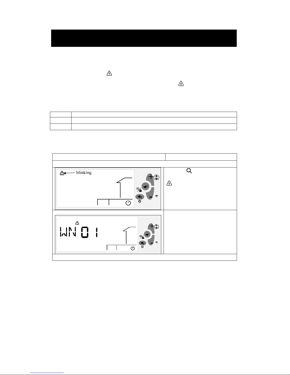
Warning Management
When a warning is detected, the corresponding warning code will be displayed on the
LCD. The warning icon will flash simultaneously.
Only the latest 10 warnings will be kept under the menu.
Upon power failure of the controller, the warning logs will be erased and
recounted
Codes Meaning
WN01 Indoor side anti-freeze in winter (WN01 on warning logs)
002 Outdoor side anti-freeze in winter (WN02 on warning logs)
Viewing Warning Logs
Display Procedures
Press down the <Enter> for 2 seconds and release it to activate the Menu mode.
When the icon is flashing, press
<Plus>/ <Minus> to navigate to the
menu, and then press <Enter> to
confirm.
Two letters “WN” will be displayed
on the LCD, continuously flashing.
Press <Enter> again to view the last
10 warning codes generated, if any.
If no warning is generated, the word
“NONE” will be displayed.
Continuously press <Exit> to exit out of the current level, and back to the normal running mode.
Warning and Alarm
Page 44

43
Alarm Management
The alarms in RWR470.10 are divided into two groups: auto reset alarms and manual
reset alarms.
1. Auto reset alarm, the user is not required to acknowledge and reset it.
2. The corresponding device will be automatically restarted once the alarm status
disappears.
3. Once a manual reset alarm is detected, the system will be stopped automatically.
The user needs to record and contact the supplier on actions what to do.
4. To acknowledge and reset the alarm press the <Enter> button.
5. Ensure that the fault has been fixed before the alarm has been reset.
When an alarm is detected:
The corresponding device icon (if any) and the icon will continuously flash.
An alarm code will be displayed on the screen.
If more than one alarm is detected, the alarm codes will be displayed successively
on the LCD screen. These will be seen by using the <plus> or <minus> buttons,
or they are manually acknowledged or reset (only for manual reset alarms).
If the system detects warnings and alarms at the same time, the warning codes will
NOT be displayed on the LCD screen.
The last 20 auto alarms and manual reset alarms generated in total are separately
logged under the auto reset alarm (AR) and manual reset alarm (MR) categories in
the menu.
Note:
The log is lost if the unit has a power de-powered.
Warning and Alarm
Page 45
44
Auto Reset Alarms
The following are codes for auto reset alarms with their meanings.
Codes Meaning
AL01 Compressor low pressure (D2)
AL02 Compressor high pressure (D3)
AL03
Low indoor side outlet water temperature protection (when ST ≤ AR01 in any
mode)
AL04
Low outdoor side outlet water temperature protection (when STo ≤ AR11 in heating
mode)
AL05
Indoor side outlet water temperature is over the highest limit in heating
mode(when ST ≥ AR03)
AL17 Flow switch alarm after the delay (AR05)
Manual Reset Alarms
The following are codes for manual reset alarms with their meanings.
Codes Meaning
AL11 RT sensor trouble (over 120 ºC or lower than -35 ºC) (X1)
AL12 ST sensor trouble (over 120 ºC or lower than -35 ºC) (X2)
AL13 OT sensor trouble (over 120 ºC or lower than -35 ºC) (X3)
AL14 HT sensor trouble (over 120 ºC or lower than -35 ºC) (X4)
AL15 ST0 sensor trouble (over 120 ºC or lower than -35 ºC) (X5)
AL16 ET sensor trouble (over 120 ºC or lower than -35 ºC) (X6)
AL18
Alarm number of compressor low pressure within 24 hours is over the
limit(AR06)
AL19
Alarm number of compressor high pressure within 24 hours is over the
limit(AR07)
AL20 Low return gas temperature protection (AR08)
AL21 High exhaust gas temperature protection (over AR10 )
Warning and Alarm
Page 46
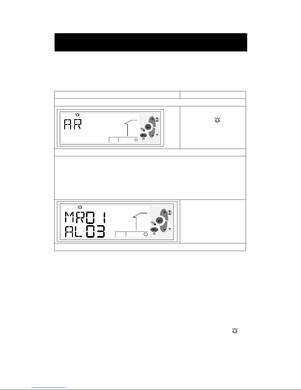
Viewing Alarm Logs
MR01 and AR01 are respectively the latest information of the manual reset alarm and
auto reset alarm.
Display Procedures
Press down the <Enter> for 2 seconds, and release it to activate the Menu mode.
Press <Plus> or <Minus> to
navigate to the menu, and
then press <Enter> to confirm.
By default, auto reset alarm
“AR” will be displayed on the
To view auto reset alarms generated, press <Enter> to continue when “AR” is displayed.
To view manual reset alarms, press<Minus> or <Plus> to navigate to the “MR” group, and then
press <Enter> to continue.
By default, the first manual reset alarm “MR01” will be displayed as follows. Press <Enter> to view
the first manual reset alarm code.
Or, press<Minus> or <Plus> to view other numbered alarms, and press<Enter> to view the specific
code.
If no alarm is generated, the
word “NONE” will be
displayed.
Continuously press <Exit> to exit out of the current level, and back to the normal running mode.
Acknowledging and Resetting Manual Reset Alarms
Any alarm detected by the system, either an auto reset alarm or a manual reset alarm
will be displayed on the LCD. However, only manual reset alarms require user’s
acknowledgement and reset.
To clear the alarm press <Enter> to acknowledge the alarm.
If the alarm status is cleared, the corresponding device icon and alarm icon that
are flashing will accordingly disappear.
Restart the system, as appropriate.
Warning and Alarm
Page 47
46
Trouble shooting
Description Possible cause Check
Power failure
faulty or disconnected
fuse
Check the mains supply phases
and active/replace fuse
Mains fault, voltage
fluctuations
notify your electricity supplier
Compressor has no
sound, no action
wrong phase sequence check phase sequence protector
Thermal relay has
tripped
Check thermal relay and
active/re set thermal relay
A/C contactor has not
closed
Check A/C contactor
Compressor internal
thermal protection
wait until compressor cool
down
controller trouble
check controller compressor
signal Q14,Q24 output
Compressor make a
sound but no action
Compressor high/low
pressure not balanced
check HP and LP readings
Voltage is too low check voltage
Low starting voltage
(single phase)
check start capacitor,
soft-starter
Compressor broken or
stuck
check compressor windings
Compressor can not
stop
A/C contactor stuck replace
controller trouble
check controller compressor
signal Q14/Q24 output
Unit heating/cooling
efficiency is low
heat exchanger is
contaminated
clean
gas filling not enough check and add gas
compressor trouble replace
Trouble Shooting
Page 48

47
Maintenance
To prevent faults due to sediment in the heat exchangers, care must be taken to ensure
that no impurities can enter either the heat source system or the heating system. In the
event that operating malfunctions due to contamination occur nevertheless the system
should be cleaned as described below.
Cleaning the Heating System
The ingress of oxygen into the heating water circuit may result in the formation of
oxidation products (rust), particularly if steel components are used. This oxygen
enters the heating system via the valves, the circulating pumps and/or plastic pipes. It
is therefore essential - in particular with respect to the piping of under-floor heating
systems - that only diffusion-proof materials are used.
A suitable corrosion protection system to prevent the formation of deposits (e.g. rust)
in the heat exchanger of the heat pump is recommended.
Residue from lubricants and sealants may also contaminate the heating water. In the
case of severe contamination leading to a reduction in the performance of the heat
exchanger in the heat pump, the system must be cleaned by a heating technician. We
recommend flushing the heat exchanger in the direction opposite to the normal flow
direction. To prevent acidic cleaning agents from entering the heating system circuit,
we recommend connecting the flushing device directly to the flow and return flow of
the heat exchanger. It is important that the system be thoroughly flushed using
appropriate neutralizing agents to prevent any damage from being caused by the
cleaning agent residue remaining in the system. Acids must be used with great care
and all relevant regulations of the employers’ liability insurance associations must be
adhered to. If in doubt, contact the manufacturer of the chemicals to be used.
Cleaning the Heat Source System
A particle filter is inserted in the heat source inlet of the heat pump to protect the heat
exchanger against the ingress of impurities. When the system is first put into
operation, the filter screen of the particle filter should be cleaned in relatively short
intervals. These intervals can be prolonged once the amount of impurities decreases.
Water Quality Requirements
The ground water should not contain any substances that could form deposits.
The use of surface water or water containing salt is not permissible. Your local water
utility can provide you with general information regarding the possible use of ground
water. Water analyses are carried out by specially-equipped laboratories.
Maintenance
Page 49
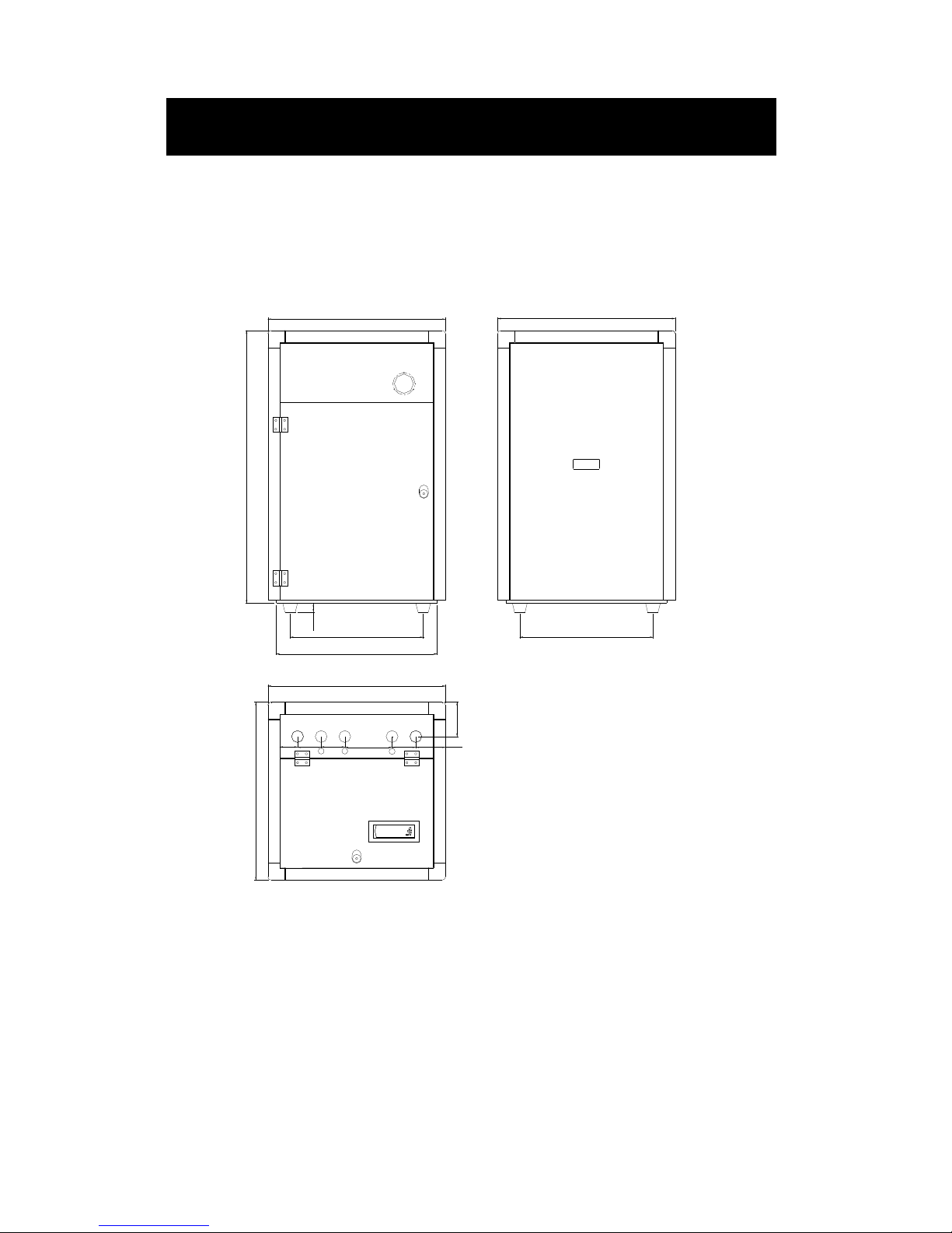
48
Dimension
Aluminium frame cabinet (GHP07 to GHP20)
Dimension
450
30
450
543
80 80
115
600
600
600
600
100
920
80
160
60
outdoor
outlet
outdoor
inlet
indoor
outlet
indoor
inlet
Sensor outlet
power cable outlet
DHW
outlet
Page 50
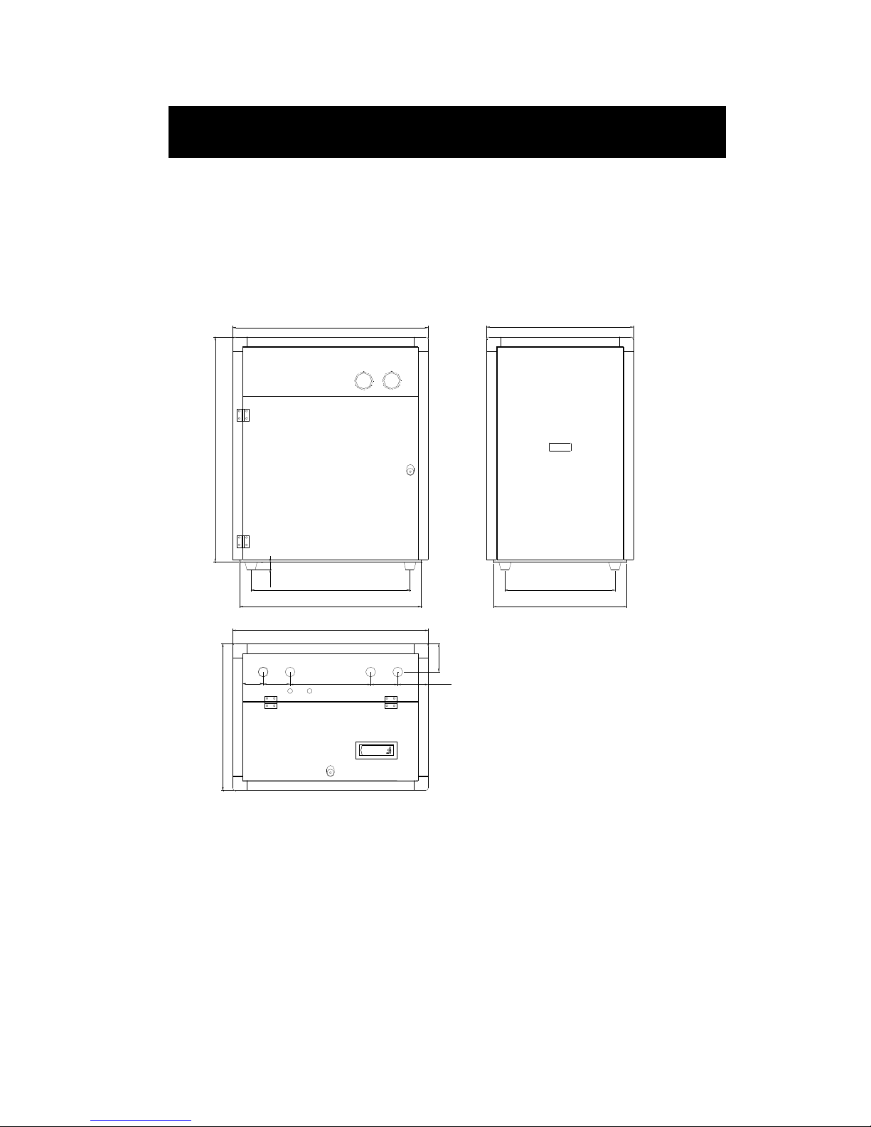
49
Aluminium frame cabinet (GHP26 GHP26B GHP30 GHP30B)
Dimension
650
30
450
543
920
800
600
743
125
110
110330
115
600
800
outdoor
outlet
outdoor
inlet
indoor
outlet
indoor
inlet
Sensor outlet power cable outlet
85
Page 51
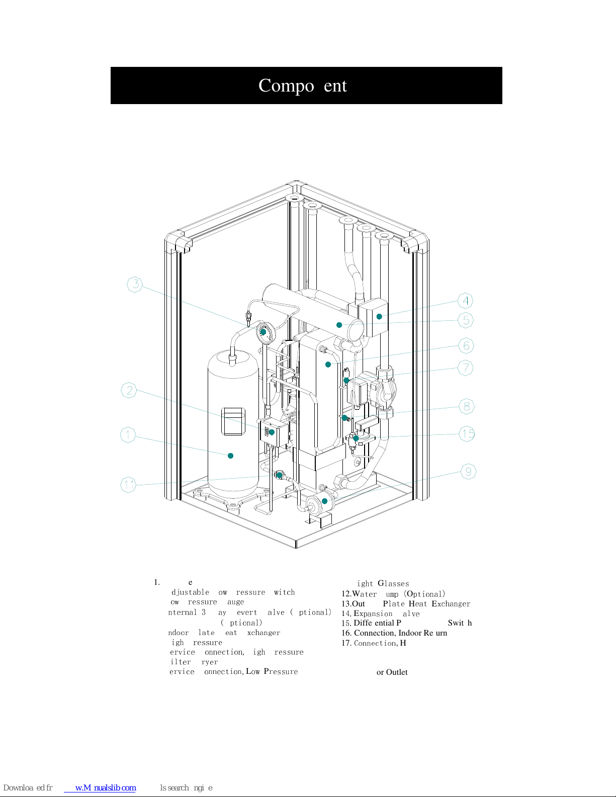
50
Components
Heating only units (from GHP07 to GHP20)
11.S
ight Glasses
12.W
ater Pump (Optional)
13.Outdoor P
late Heat Exchanger
14.Expansion Valve
15.
Differential Pressure Flow Switch
16. Connection, Indoor Return
17.
Connection,
Heating Flow
18. Connection, Hot Water Flow
19. Outdoor Inlet
20. Outdoor Outlet
1. Compressor
2. A
djustable Low Pressure Switch
3. L
ow Pressure Gauge
4. I
nternal 3 Way Revert Valve (Optional)
5. Electric Heater (O
ptional)
6. I
ndoor Plate Heat Exchanger
7. H
igh Pressure
Switch
8. S
ervice Connection,High Pressure
9. F
ilter Dryer
10.S
ervice Connection,Low Pressure
Components
Page 52
51
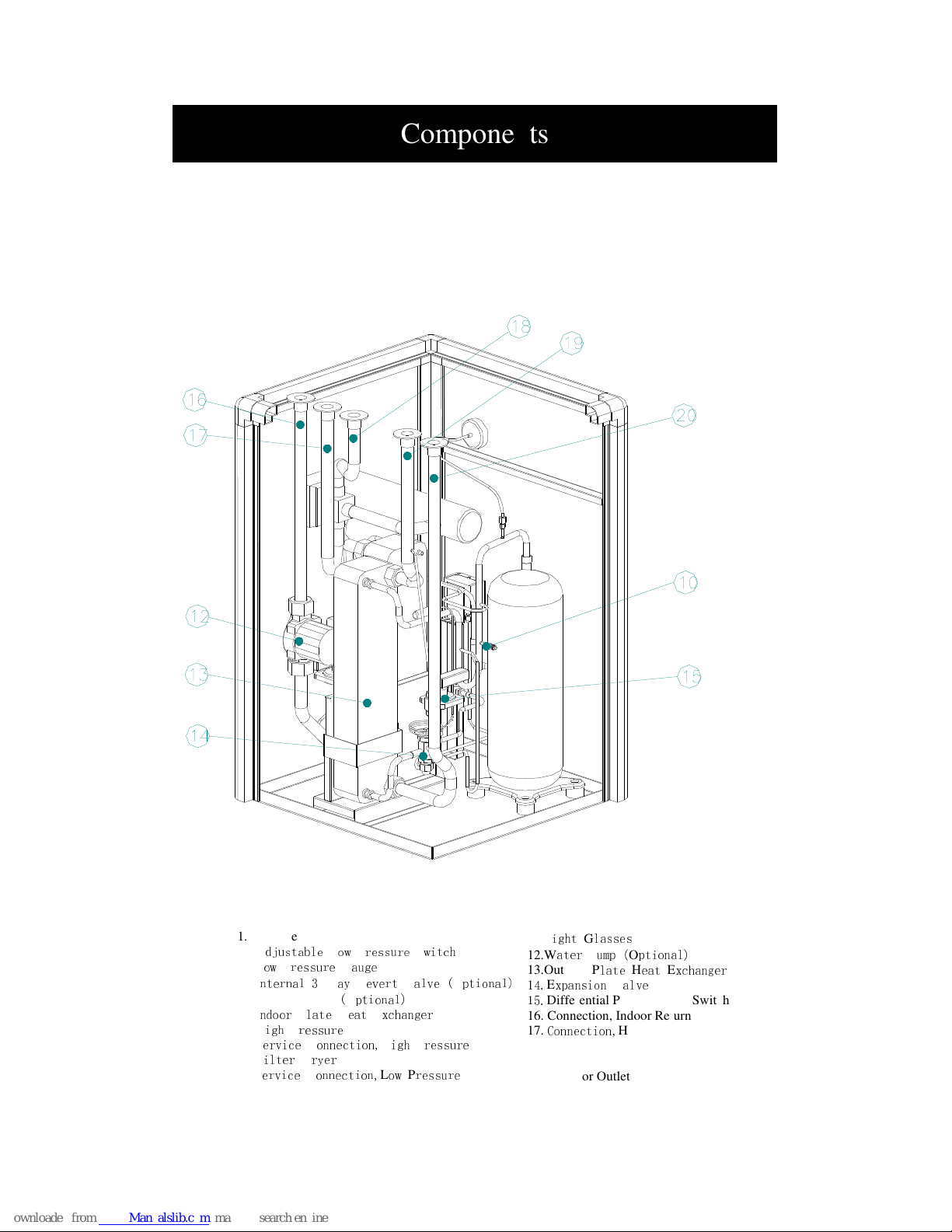
Heating only units (from GHP07 to GHP20)
11.S
ight Glasses
12.W
ater Pump (Optional)
13.Outdoor P
late Heat Exchanger
14.Expansion Valve
15.
Differential Pressure Flow Switch
16. Connection, Indoor Return
17.
Connection,
Heating Flow
18. Connection, Hot Water Flow
19. Outdoor Inlet
20. Outdoor Outlet
1. Compressor
2. A
djustable Low Pressure Switch
3. L
ow Pressure Gauge
4. I
nternal 3 Way Revert Valve (Optional)
5. Electric Heater (O
ptional)
6. I
ndoor Plate Heat Exchanger
7. H
igh Pressure
Switch
8. S
ervice Connection,High Pressure
9. F
ilter Dryer
10.S
ervice Connection,Low Pressure
Components
Page 53
52
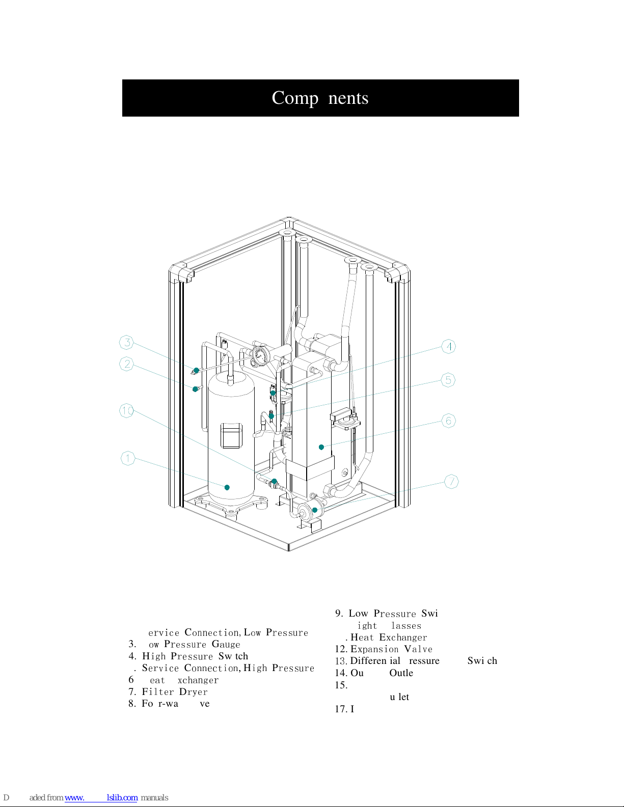
Heating and cooling units (from GHP07B to GHP20B)
1. Compressor
2. S
ervice Connection,Low Pressure
3. L
ow Pressure Gauge
4. H
igh Pressure
Switch
5. S
ervice Connection,High Pressure
6. H
eat Exchanger
7. F
ilter Dryer
8. Four-way valve
9. Low P
ressure
Switch
10. S
ight Glasses
11. H
eat Exchanger
12. E
xpansion Valve
13.
Differential Pressure Flow Switch
14. Outdoor Outlet
15. Outdoor Inlet
16. Indoor Outlet
17. Indoor Inlet
Components
Page 54
53
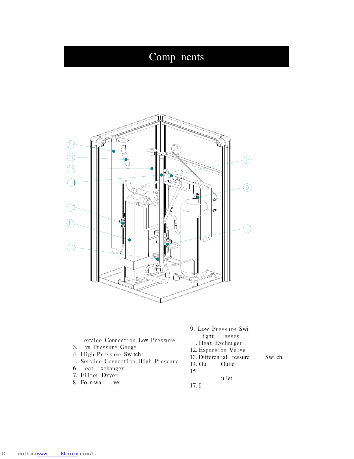
Heating and cooling units (from GHP07B to GHP20B)
1. Compressor
2. S
ervice Connection,Low Pressure
3. L
ow Pressure Gauge
4. H
igh Pressure
Switch
5. S
ervice Connection,High Pressure
6. H
eat Exchanger
7. F
ilter Dryer
8. Four-way valve
9. Low P
ressure
Switch
10. S
ight Glasses
11. H
eat Exchanger
12. E
xpansion Valve
13.
Differential Pressure Flow Switch
14. Outdoor Outlet
15. Outdoor Inlet
16. Indoor Outlet
17. Indoor Inlet
Components
Page 55
54
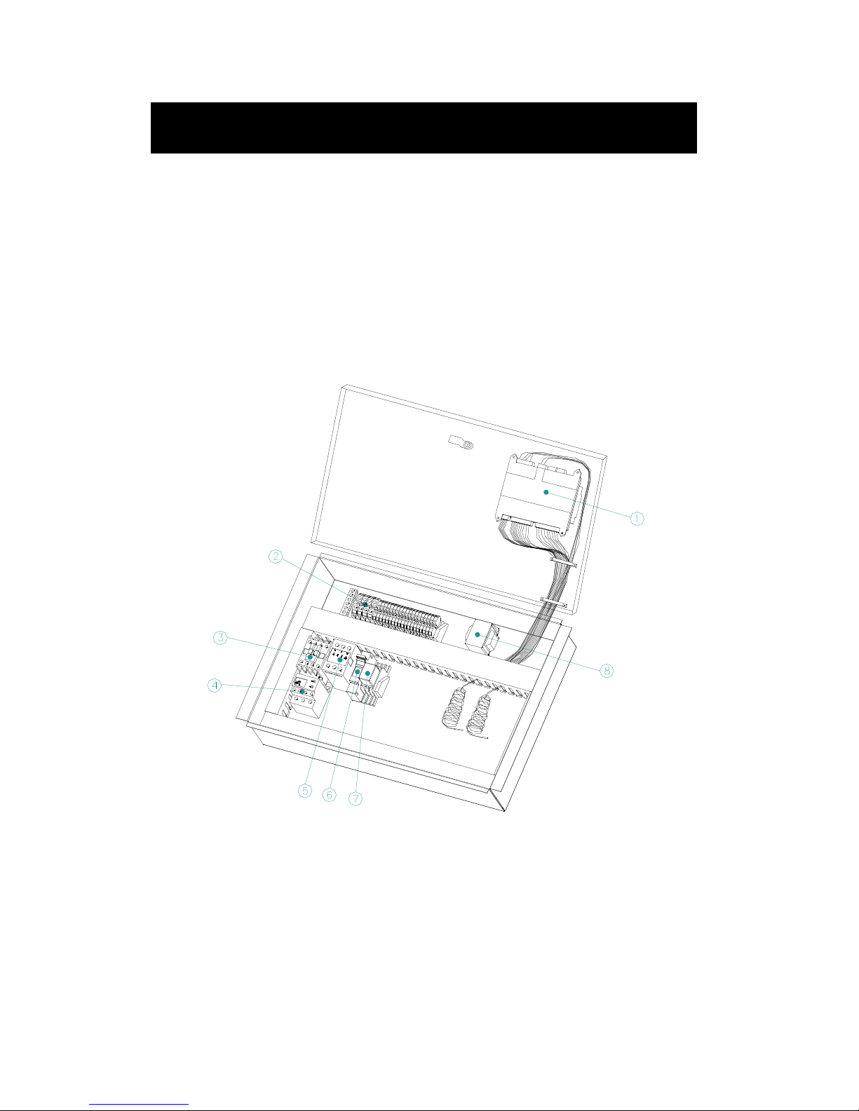
Triple phase control board (GHP10, GHP10B, GHP13, GHP13B,
GHP15, GHP15B, GHP20, GHP20B,GHP26, GHP26B ,GHP30,
GHP30B)
1. Siemens controller
2. Connection terminal strip
3. A/C contactor
4. Thermal relay
5. Phase relay
6. Circuit breaker
7. Three way valve relay
8. Transformer
Components
Page 56
55
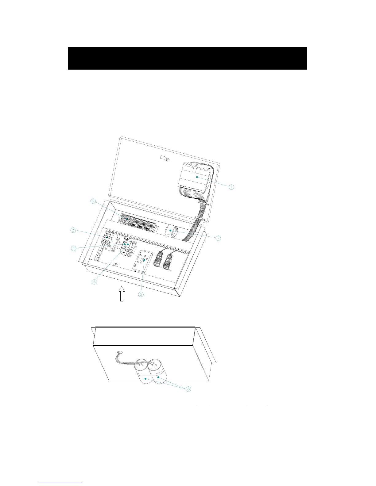
Single phase control board (GHP07 ,GHP07B GHP09, GHP09B,
GHP12, GHP12B)
Components
1. Siemens controller
2. Connection terminal strip
3. A/C contactor
4. Circuit breaker
5 Three way valve relay
6. Soft starter
7. Transformer
8. Capacitor
Page 57
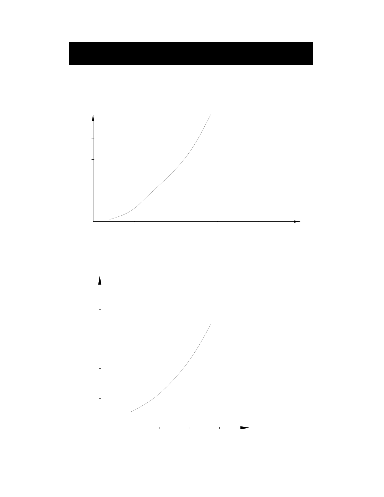
56
Pressure drop curve
m 3/h
10
20
30
1.0
2.0 3.0 4.0
40
KPa
m3/h
10
20
30
1.0
2.0 3.0 4.0
40
KPa
GHP10B
GHP9B
GHP10
GHP9
0
Pressure Drop Curve
GHP07
GHP07 GHP07
GHP07
GHP07B
GHP07BGHP07B
GHP07B
Page 58
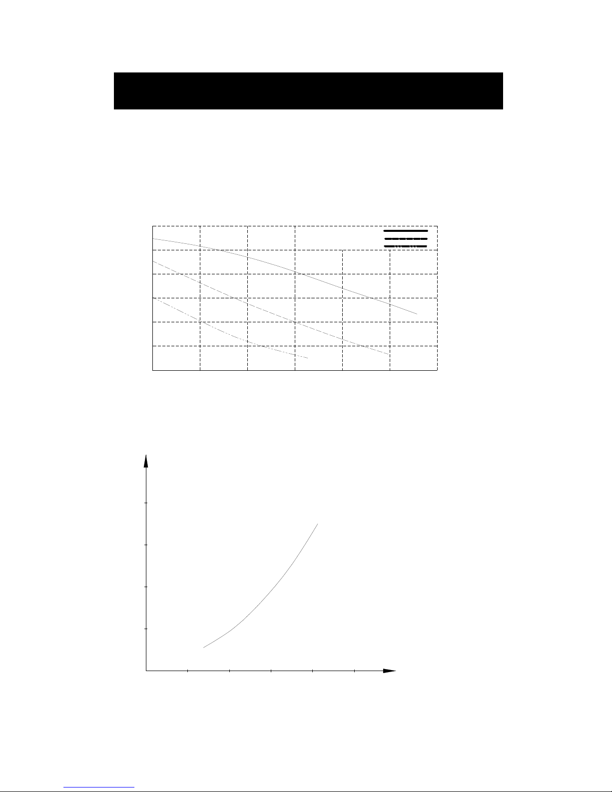
57
Optional internal hot water pump curve
GHP07 GHP09 GHP10
0 0.5
1
Flow(m3/H)
Pressure(mCE)
Wilo-star-RS 25/6
Maximum speed
Medium speed
Mini speed
2
3
4
5
6
1.0 1.5 2.0 2.5 3.0
m3/h
10
20
30
1.0
2.0 3.0 4.0
40
KPa
GHP13B
GHP12B
5.0
GHP13
GHP12
0
Pressure Drop Curve
Page 59
58
m3/h
10
20
30
1.0
2.0 3.0 4.0
40
KPa
5.0
GHP15B
GHP15
0
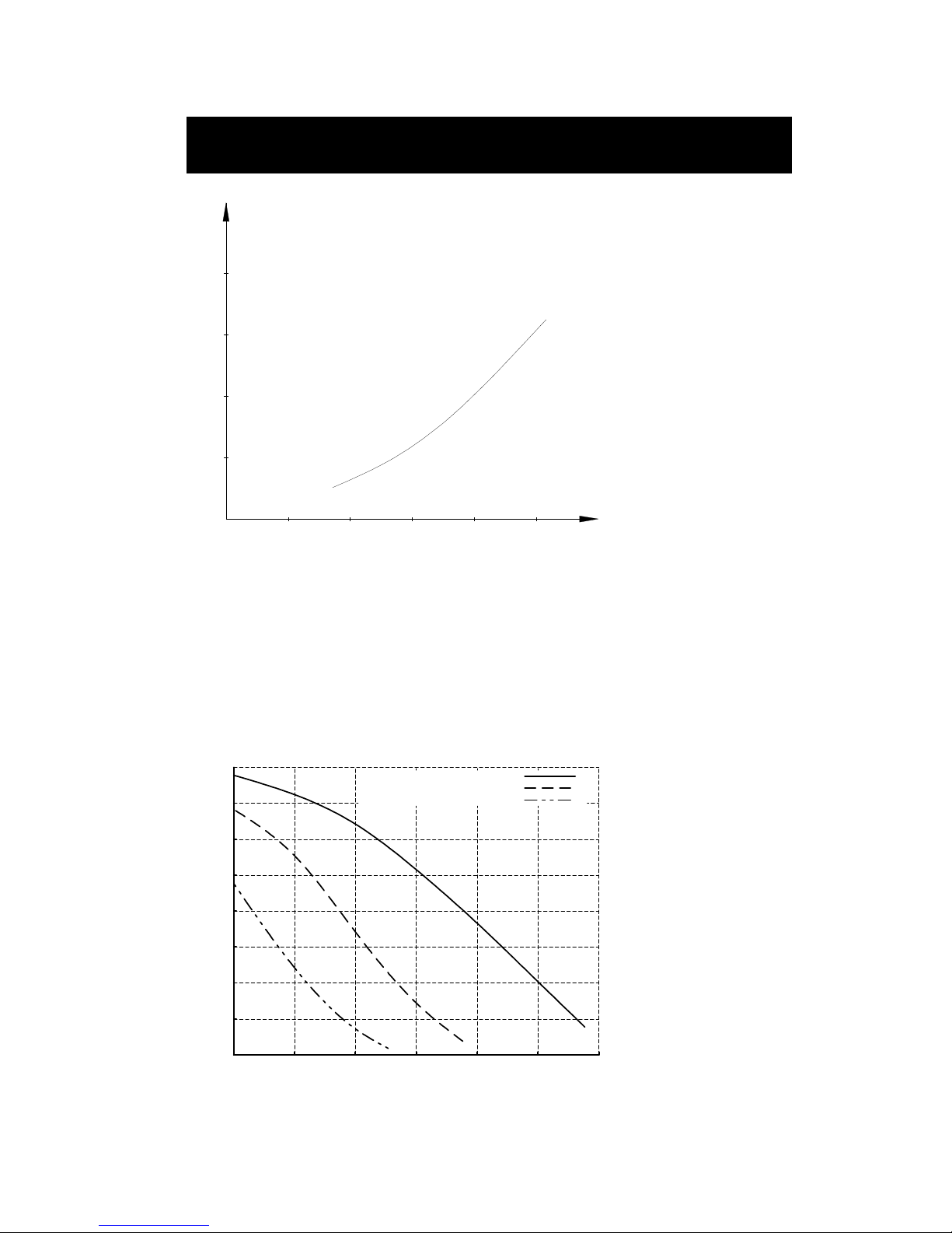
Optional internal hot water pump curve
0
1
2
3
4
5
6
7
8
0
1 2 3 4 5 6
Flow (m3/H)
Maximum speed
Medium speed
Mini speed
Pressure (mCE)
Wilo -star -RS25/8
Pressure Drop Curve
GHP12 GHP13 GHP15
Page 60
59
m3/h
10
20
30
1.0
2.0 3.0 4.0
40
KPa
GHP2 0B
5.0
GHP2 0
0
m3/h
10
20
30
1.0
2.0 3.0 4.0
40
KPa
5.0 6.0 7.0 8.0509.0
GHP26B
GHP30B
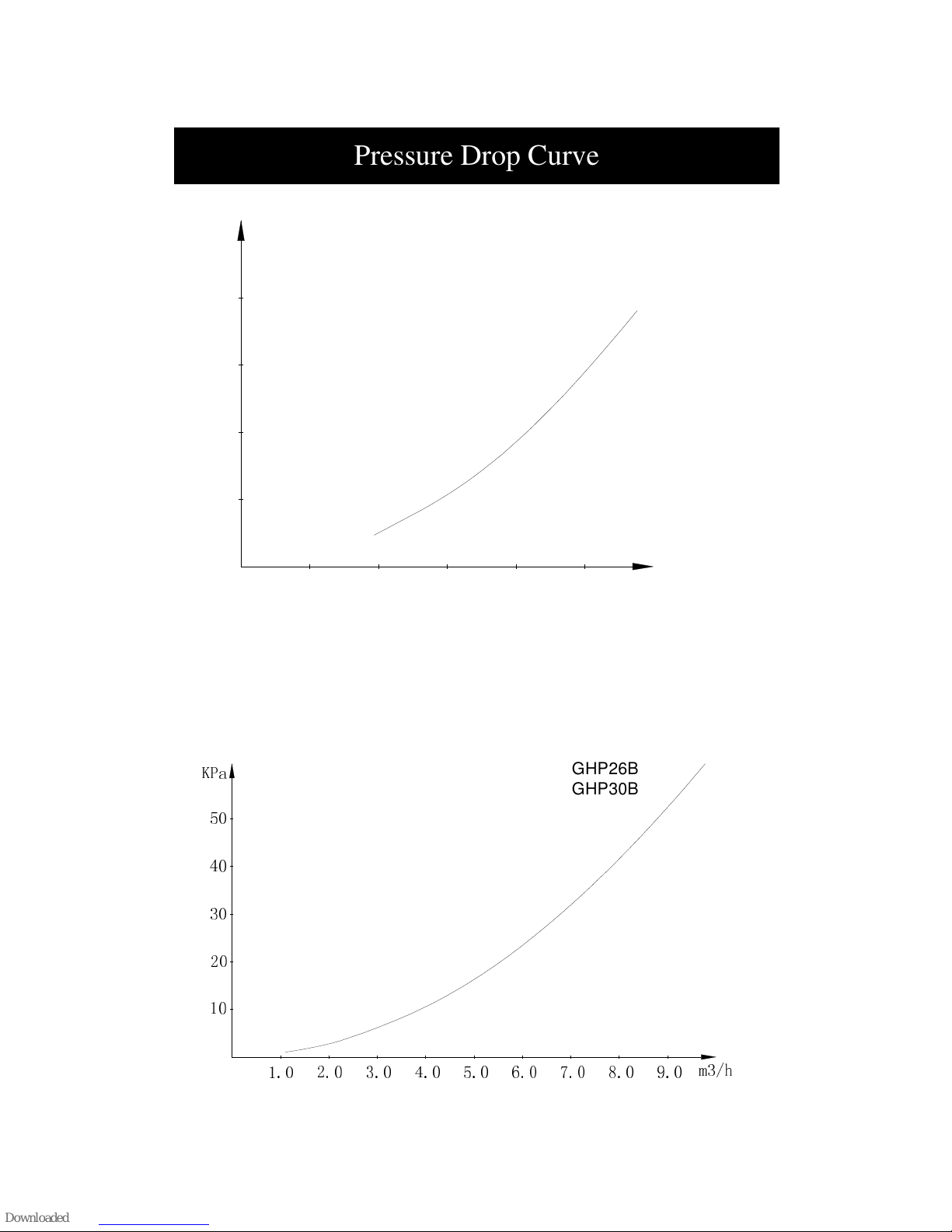
Pressure Drop Curve
Page 61
60
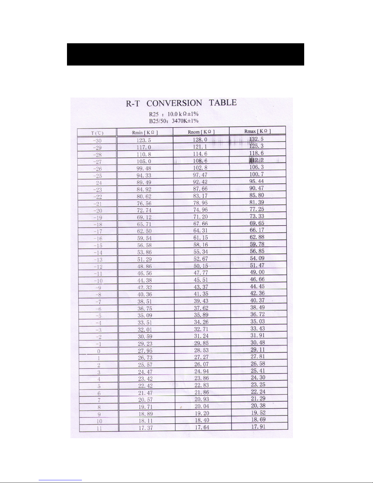
Temperature and sensor resistance table
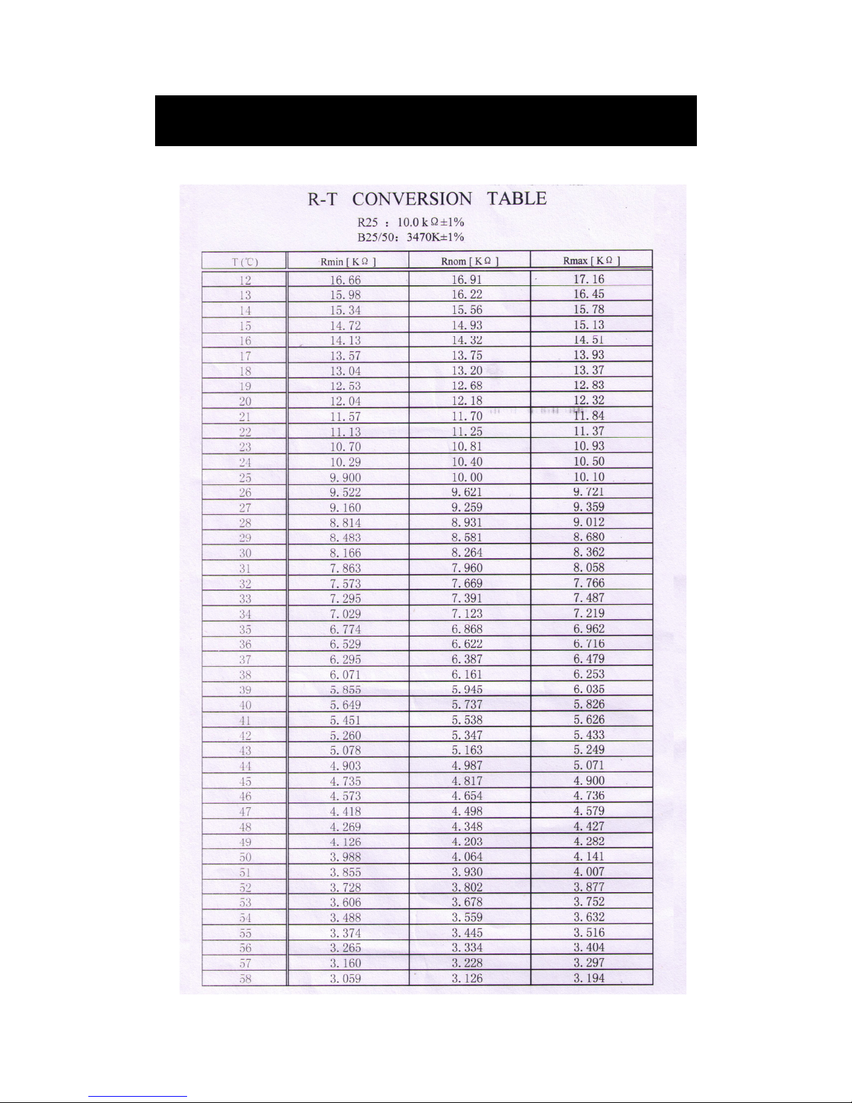
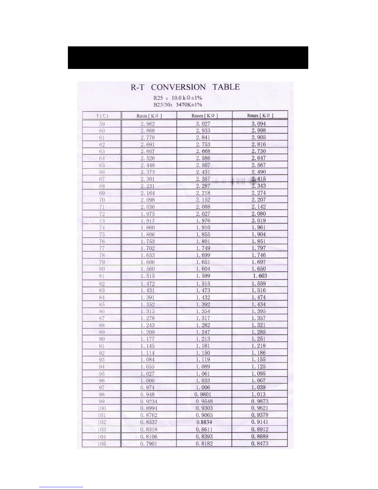
The sensors RT,ST,OT,HT,CT,ET are NTC10K.
Temperature and sensor resistance table
Page 62
61
Temperature and sensor resistance table
Page 63
62
Temperature and sensor resistance table
Page 64
63
Technical specifications
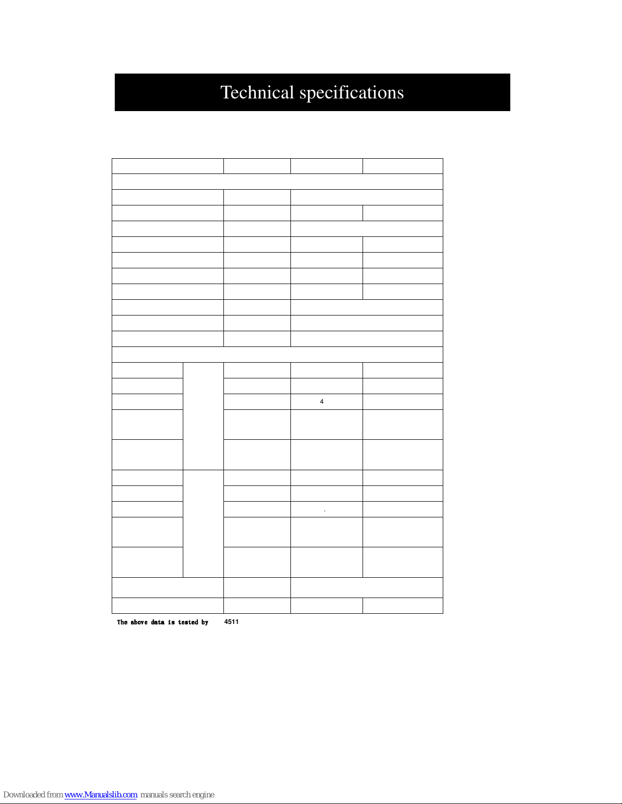
Heating only units:
Heat pump Type GHP07 GHP09 GHP12 GHP10 GHP13 GHP15 GHP20
Dimensions,weights,connection dimensions
Dimensions HxWxD
960x600X600
Weight kg 105 130 140 130 140 150 160
Refrigerant Type R410A
Filling weight kg 1.35 1.60 1.70 1.60 1.70 1.90 2.15
Permissible operating pressure Mpa 4.2 4.2 4.2 4.2 4.2 4.2 4.2
Pipe connector-hot side Inch G1” G1” G11/4” G1” G11/4” G11/4” G11/2”
Pipe connector-cold side Inch G1” G1” G11/4” G1” G11/4” G11/4” G11/2”
Evaporator Type Brazed plate heat exchanger
Condenser Type Brazed plate heat exchanger
Compressor
1xRotary 1xScroll
Performance Heat pump
Heat output
at
B0/W35
kW 7.0 8.6 11.8 10.0 13.0 15.5 20.3
Power consumption
kW 1.67 1.95 2.70 2.22 2.90 3.50 4.60
Performance factor
4.19 4.41 4.37 4.5 4.48 4.43 4.41
Hot side volume
flow
m3/h 1.20 1.48 2.03 1.72 2.24 2.67 3.49
Cold side volume
flow
m3/h 1.53 1.91 2.61 2.23 2.90 3.44 4.50
Heat output
at
W10/W35
kW 9.0 11.0 15.0 12.7 16.3 19.5 25.7
Power consumption
kW 1.69 2.03 2.80 2.27 2.96 3.57 4.68
Performance factor
5.33 5.42 5.36 5.59 5.51 5.46 5.49
Hot side volume
flow
m3/h 1.55 1.89 2.58 2.18 2.80 3.35 4.42
Cold side volume
flow
m3/h 2.10 2.57 3.50 2.99 3.82 4.57 6.03
Power Type
Single phase
Triple phase
Sound power level dB(A) 49 47 48 47 48 48 48
The above data is tested by
The above data is tested by The above data is tested by
The above data is tested by
EN14511
Technical specifications
Page 65
64
Heating only units:
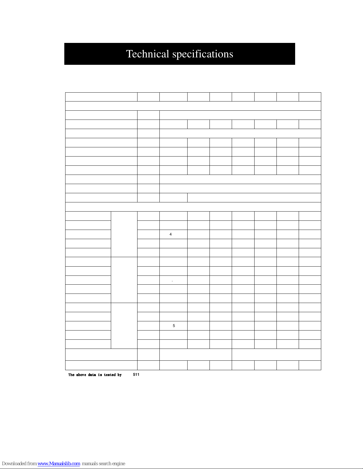
Heat pump Type GHP26 GHP30
Dimensions,weights,connection dimensions
Dimensions HxWxD 960x600X800
Weight kg 190 195
Refrigerant Type R410A
Filling weight kg 3.40 3.80
Permissible operating pressure Mpa 4.2 4.2
Pipe connector-hot side Inch G11/2” G11/2”
Pipe connector-cold side Inch G11/2” G11/2”
Evaporator Type Brazed plate heat exchanger
Condenser Type Brazed plate heat exchanger
Compressor
2xScroll
Performance Heat pump
Heat output
at
B0/W35
kW 26.0 31.0
Power consumption
kW 5.80 7.00
Performance factor
4.48 4.43
Hot side volume
flow
m3/h 4.47 5.33
Cold side volume
flow
m3/h 5.79 6.88
Heat output
at
W10/W35
kW 32.6 39.0
Power consumption
kW 5.92 7.14
Performance factor
5.51 5.46
Hot side volume
flow
m3/h 5.61 6.71
Cold side volume
flow
m3/h 7.65 9.13
Power Type Triple phase
Sound power level dB(A) 49 49
The above data is tested by
The above data is tested by The above data is tested by
The above data is tested by
EN14511
Technical specifications
Page 66
65
Heating and Cooling units:
Heat pump Type GHP07B GHP09B GHP12B GHP10B GHP13B GHP15B GHP20B
Dimensions,weights,connection dimensions
Dimensions HxWxD 960x600X600
Weight kg 110 135 145 135 145 155 165
Refrigerant Type R410A
Filling weight kg 1.35 1.7 1.8 1.7 1.8 2 3.4
Permissible operating pressure Mpa 4.2 4.2 4.2 4.2 4.2 4.2 4.2
Pipe connector-hot side Inch G1” G1” G11/4” G1” G11/4” G11/4” G11/2”
Pipe connector-cold side Inch G1” G1” G11/4” G1” G11/4” G11/4” G11/2”
Evaporator Type Brazed plate heat exchanger
Condenser Type Brazed plate heat exchanger
Compressor
1xRotary 1xScroll
Performance Heat pump
Heat output
at B0/W35
kW 7.0 8.6 11.8 10.0 13.0 15.5 20.3
Power consumption kW 1.67 1.95 2.70 2.22 2.9 3.5 4.60
Performance factor
4.19 4.41 4.37 4.5 4.48 4.43 4.41
Hot side volume flow m3/h 1.20 1.48 2.03 1.72 2.24 2.67 3.49
Cold side volume flow m3/h 1.53 1.91 2.61 2.23 2.90 3.44 4.50
Heat output
at
W10/W35
kW 9.0 11.00
15.00
12.7 16.3 19.5 25.7
Power consumption kW 1.69 2.03 2.80 2.27 2.96 3.57 4.68
Performance factor
5.33 5.42 5.36 5.59 5.51 5.46 5.49
Hot side volume flow m3/h 1.55 1.89 2.58 2.18 2.80 3.35 4.42
Cold side volume flow m3/h 2.10 2.57 3.50 2.99 3.82 4.57 6.03
Cool output
at W35/W7
kW 7.7 9.30 12.70 10.60 13.90 16.30 21.80
Power consumption kW 1.68 2.00 2.70 2.20 2.85 3.40 4.50
Performance factor
4.58 4.65 4.70 4.82 4.88 4.79 4.84
Inside volume flow m3/h 1.32 1.60 2.18 1.82 2.39 2.80 3.75
Outside volume flow m3/h 1.61 1.94 2.65 2.20 2.88 3.39 4.52
Power Type
Single phase
Triple phase
Sound power level dB(A) 49 47 48 47 48 48 48
The above data is tested by
The above data is tested by The above data is tested by
The above data is tested by
EN14511
Technical specifications
Page 67
66
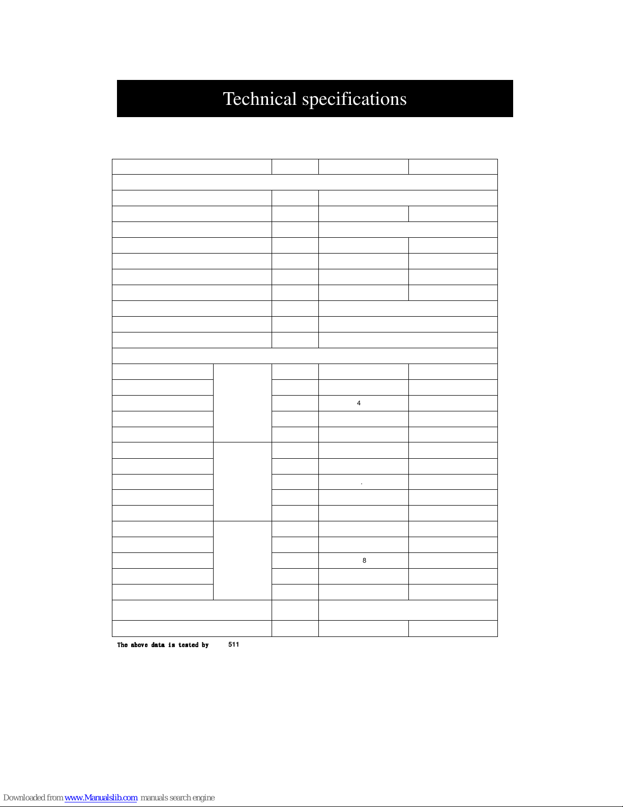
Heating and Cooling units:
Heat pump Type GHP26B GHP30B
Dimensions,weights,connection dimensions
Dimensions HxWxD 960x600X800
Weight kg 195 200
Refrigerant Type R410A
Filling weight kg 3.6 4
Permissible operating pressure Mpa 4.2 4.2
Pipe connector-hot side Inch G11/2” G11/2”
Pipe connector-cold side Inch G11/2” G11/2”
Evaporator Type Brazed plate heat exchanger
Condenser Type Brazed plate heat exchanger
Compressor
2xScroll
Performance Heat pump
Heat output
at B0/W35
kW 26.0 31.0
Power consumption kW 5.80 7.00
Performance factor
4.48 4.43
Hot side volume flow m3/h 4.47 5.33
Cold side volume flow m3/h 5.79 6.88
Heat output
at W10/W35
kW 32.6 39.0
Power consumption kW 5.92 7.14
Performance factor
5.51 5.46
Hot side volume flow m3/h 5.61 6.71
Cold side volume flow m3/h 7.65 9.13
Cool output
at W35/W7
kW 27.80 32.60
Power consumption kW 5.70 6.80
Performance factor
4.88 4.79
Inside volume flow m3/h 4.78 5.61
Outside volume flow m3/h 5.76 6.78
Power Type Triple phase
Sound power level dB(A) 49 49
The above data is tested by
The above data is tested by The above data is tested by
The above data is tested by
EN14511
Technical specifications
 Loading...