

HISEER AS10/LF, AS13/LF Operation Installation Maintenance Manual
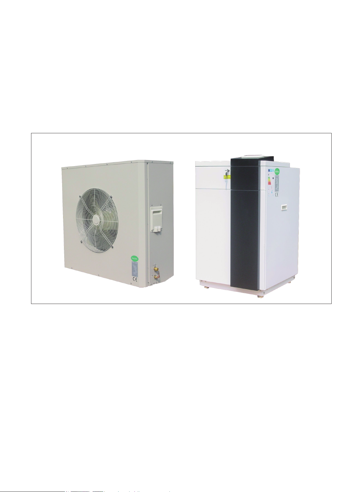
AIR TO WATER HEAT PUMP
—— Split EVI
Operation, installation &maintenance manual
V.201510
The installation of this unit is to adhere to all local
Building Codes and Standards

Index
Working principle ............................................................................................................................................ 1
Nomenclature ................................................................................................................................................... 2
Specialist Tools ................................................................................................................................................ 3
Pre-installation ................................................................................................................................................. 4
Installation Location ........................................................................................................................................ 5
Positioning ....................................................................................................................................................... 6
Buffer Tank ...................................................................................................................................................... 7
Frost Protection ................................................................................................................................................ 8
System Overview ............................................................................................................................................. 9
System Overview ........................................................................................................................................... 11
Installation ...................................................................................................................................................... 13
Electrical connection ...................................................................................................................................... 16
User Guide ..................................................................................................................................................... 20
Service Parameters: ........................................................................................................................................ 33
Service Guide ................................................................................................................................................. 34
Commissioning and Adjusting ....................................................................................................................... 41
Commissioning Form..................................................................................................................................... 42
Alarms ............................................................................................................................................................ 43
Maintenance ................................................................................................................................................... 46
Dimensions .................................................................................................................................................... 48
Water Pressure Plots....................................................................................................................................... 49
AS10/LF ......................................................................................................................................................... 49
AS13/LF ......................................................................................................................................................... 51
Temperature and sensor resistance table ........................................................................................................ 52
Components ................................................................................................................................................... 54
Electric wiring diagram .................................................................................................................................. 56
Technical Specications ................................................................................................................................. 58
Working principle
RT
Buffer tank
①
Outdoor unit
Indoor unit
1. The low pressure and low temperature liquid
refrigerant coming out of expansion valve exacts
heat energy from the air through finned coil heat
exchanger①and evaporates into gas state.
2. The gas state refrigerant is sucked into compressor
and compressed to high pressure and high temp.
②
gas .
3. The high pressure and high temp. gas discharged by
compressor releases its heat energy to water in plate
exchanger③and condensed to liquid state.
4. The liquid s tate r e frig e rant is exp a nded in
thermostatic expansion valve
and become low
④
pressure and low temperature liquid refrigerant.
②
⑤
④
⑥
F
③
5. The cycle repeats.
6. When EVI condition is met, EVI expansion valve
will open and some liquid gas will expand
⑥
and the gas will be inject into compressor middle
containment after absorbing heat from main branch
liquid gas in the economizer
. With this EVI
⑤
function, not only heat pump heating capacity and
COP will increase ,but also compressor discharge
temp. could be controlled within safety limit and
the heat pump workable ambient temp. could be
extended to -25
℃。
1
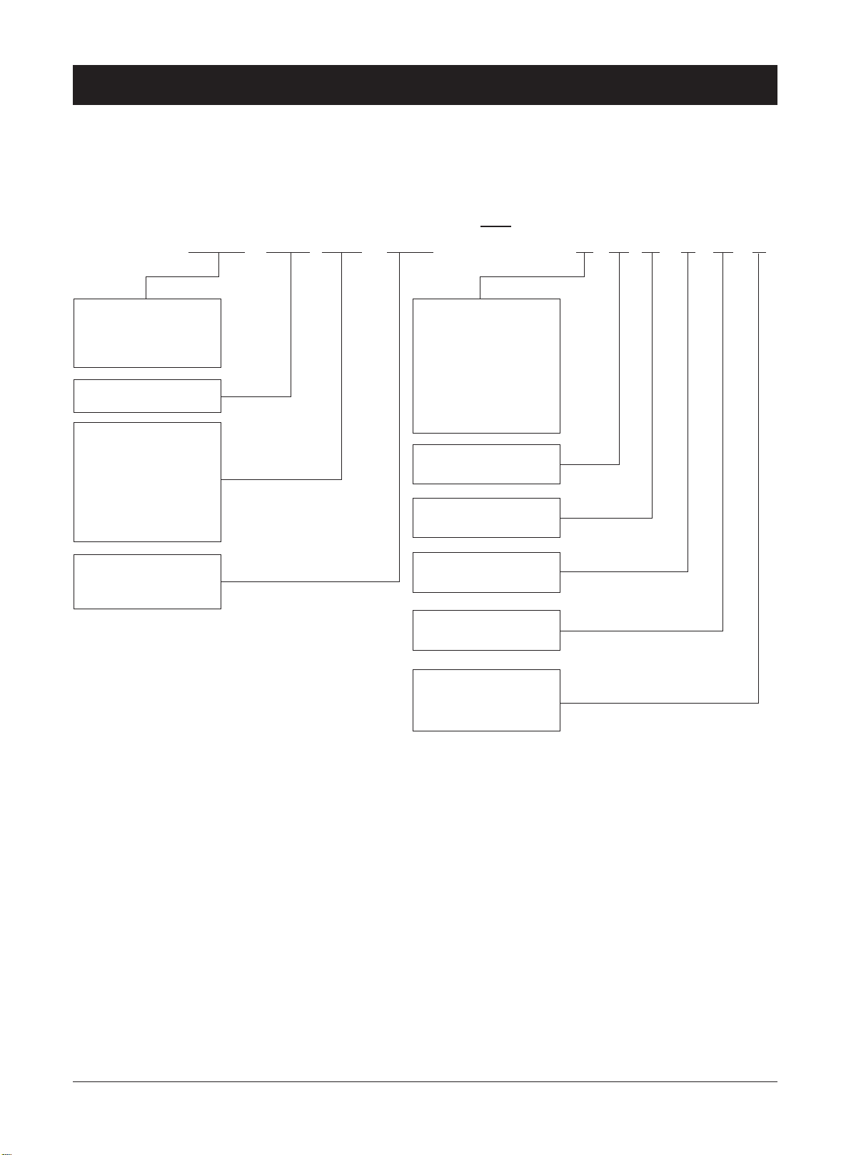
Nomenclature
AS10/LF
Air source heat pump
With Carel controller
Rated heating output
L:EVI for low ambient
temp.
B:Standard Heating
and Cooling
Default: Standard
Heating only
F:Split
NONE: Monoblock
D6NNHE
B: 220V, 3~50/60Hz
C: 380V, 3~50Hz
380-400V, 3~60Hz
D: 380-415V,3~50Hz
440V, 3~60Hz
P: 208-230V, 1~60Hz
Q: 220-240V, 1~50Hz
6: 60Hz
default: 50Hz
P: with pump
N: none
V: with 3 way valve
N: none
H: with 3 way valve
N: none
E:R410A
G:R407C
F:R22 R417A
2

Specialist Tools
Specialist tools that might be used on installation, commissioning and maintenance.
The tools as exclusive tools for R410A refrigerant.
1 Gauge manifold ·Only for R410A
·Use the existing tting specications.(G1/4”)
·Use high-tension side pressure of 5.3MPa·G or over.
2 Charge hose ·Only for R410A
·Use pressure performance of 5.09MPa·G or over.
3 Electronic scale
4 Gas leak detector ·Use the detector for R410A.
5.Vacuum pump (pump with reverse ow preventive function)
6 Refrigerant charge base
7 Refrigerant cylinder ·Only for R410A Top of cylinder (Pink)Cylinder with syphon
8 Refrigerant recovery equipment
9. Torque wrench
10. Multi-meter
11. screwdrivers
3
Pre-Installation
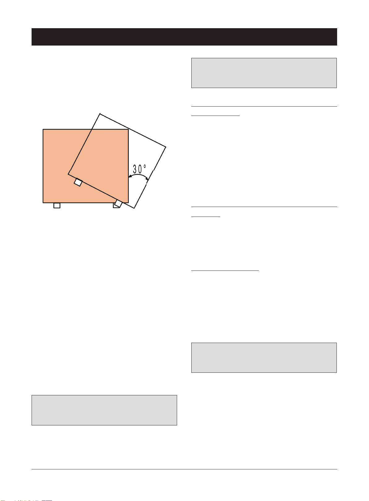
Movement and Storage
The unit must not be transported, moved or stored at
greater than a 30° angle from the upright position. Store
the unit in a dry area until required.
The unit must be installed by a suitably qualified
tradesperson and all electrical wiring must be completed
by a licensed electrical contractor in accordance with
all local Standards.
Note: ensure the correct refrigerant gas is used to
recharge the unit as an incorrect gas can cause
damage beyond repair to the compressor.
Do not use oxygen to purge lines or to pressurize a unit
for any purpose. Oxygen gas reacts violently with oil,
grease and other common substances. Use only refrigerant
or dry nitrogen for testing.
Never exceed the specied maximum operating pressures.
Do not un-weld or ame cut the refrigerant lines
including any refrigerant circuit components
until the entire refrigerant (liquid and vapour)
has been removed from unit. Traces of vapour
should be displaced with dry nitrogen.
Refrigerant in contact with an open ame will produces
toxic gases.
Ensure that the necessary safety protection
equipment is available when servicing. Have the
appropriate re extinguishers for that system.
Safety
The installation must be overseen by a qualified
person, in order to avoid an incorrect installation that
could damage to the unit or cause injuries to people.
Any faults and or leaks must be repaired immediately
before the unit continues to operate. If repairs have
been carried out to the unit then operation of the safety
devices and parameter must be rechecked.
If a refrigerant leak occurs, remove the complete charge
using a recovery unit and store the refrigerant in mobile
container.
Note: care is to be taken as the refrigerant
can breakdown due to high temperature, these
refrigerants by-products are dangerous.
Once the leak has been repaired recharge the unit with
the correct filling weight and the type found on the
unit’s nameplate.
Do not siphon refrigerant.
Avoid spilling liquid refrigerant onto the skin or
splashing it into the eyes. Use safety goggles.
Wash any spills from the skin with soap and
water. If liquid refrigerant enters the eyes,
immediately and abundantly ush the eyes with
water and consult medical advice.
Note: Never apply an open flame or live stream
to a refrigerant container. This can dangerously
overpressure and cause an explosion.
Compressor oil type :
3MA POE
The heating system must be pressure tested and
air vented completely.
Filling water and supplemented water must be
drinking water quality (colourless, clear ,free
from sediments)
Filling water and supplemented water must be
pre-ltered. (pore size max. 5um)
4
Installation Location
The unit must be installed on a solid level surface
on a concrete pad foundation not connected to the
house foundation. Rubber cushions can be added to
reduce vibration and noise if required.
The unit should be place so that it is well away
from bedrooms or noise sensitive areas including
neighbour’s section boundaries. (The unit will
produce noise that is above the minimum 45
decibel rating).
The unit should be well ventilated with no
obstructions and kept level at all times.
Ensure there is good drainage around installation
area and make sure this water cannot run out onto
paths as it may cause ice or slime build up which is
undesirable. (The unit can produce large volumes
of condensation water when running in high
humidity zones. There is also a large run off when
the unit melts ice during a defrost cycle).
The unit must be installed level in both axes (less
than 2mm tolerance per meter)
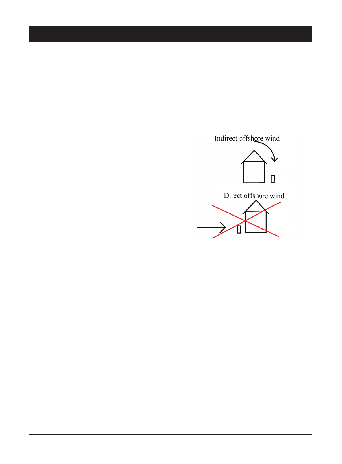
Locations exposed to strong winds should be
avoided otherwise baffles may be necessary to
deflect strong winds and to prevent snow from
blowing directly into the unit. They must not
restrict air ow into the unit.
Avoid locations exposed to machine oil vapour,
salty air, thermal springs sulphur gases or other
harsh substances
If operation in temperatures below 0°C for
prolonged periods or locations where the snow may
fall the unit must be raised at least 300mm off the
ground. This is necessary to avoid ice build-up on
the unit’s chassis.
Keep suitable distance between the unit and the
building to ensure the normal running of the unit
and enough room is available for maintenance.
5
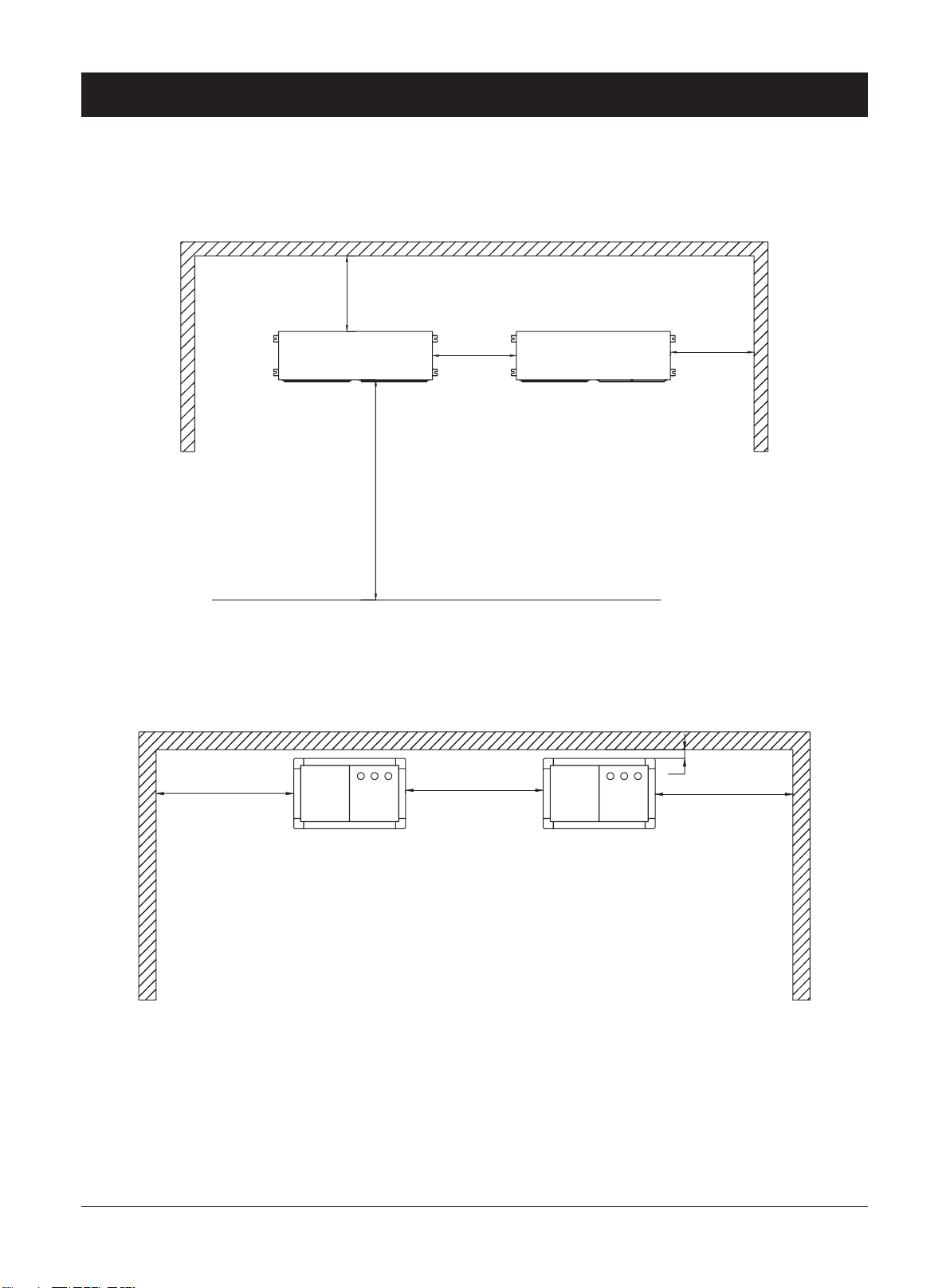
Positioning
Outdoor unit
550mm
ı
ı
ı
600mm
1600mm
ı
600mm
800
Indoor unit
800
50
800
6

Buffer Tank
A buffer tank is recommended to ensure a trouble free
heat pump operation. A suitable buffer tank can avoid
excessive heat pump cycling (switching on and off).
The buffer tank provides a hydraulic separation from
the volume ow in the heat pump and heating circuits.
The volume flow in the heat pump circuit remains
constant, even if the heating circuit volume flow is
reduced by thermostatic valves.
If the total of the systems water volume is less than
12L/KW then a buffer tank should be added to reduce
the compressor from ON/OFF cycling. This will
prolong the compressor life span.
When a buffer tank is installed, the heating system
will absorb energy from the buffer tank first. To save
energy consumption ,install the indoor pump P1 that
is switched on only when compressor is on. This is
by changing EV01 indoor pump mode to “work by
regulation”.
Inlet water temp sensor should be taken out of the unit
and put into buffer tank’s sensor pocket. The Inlet water
temp sensor is located on inlet water pipe. The Inlet
water temperature sensor B1 in the buffer tank will
control the tank temperature by starting and stopping
the compressor and pump together as required.
If Inlet water temp sensor has not been changed to
buffer tank’s sensor pocket when EV01 has been
changed to “work by regulation”, when the unit reaches
its set temperature ,the compressor will stop, pump
P1 will also stop accordingly due to EV01 being set
to “work by regulation”. When this occurs ,there is no
water circulation between the heat pump and buffer
tank. Inlet water temp will keep its stopped temperature
,not the buffer tank water temperature. Inlet water
temp sensor B1 then can not switch on compressor and
pump P1 even when buffer tank water is getting cold.
Changing the Inlet water temp sensor into the buffer
tank will avoid this problem.
7

Frost Protection
The plate heat exchanger, the piping and the hydraulic
pump can be damaged by frost, despite the built-in anti-
freeze protection of the unit.
In frost prone areas refer to installation location instructions.
To avoid freezing-up of the water contained in the
system, one of the precautions must be taken during
winter:
1. Drain the water from the system, using the drains in
the lower part of the unit.
2. Add the correct percentage of glycol antifreeze to the
water circuit.
3. The power to the unit must be on all the time so unit
can start circulation pump and auxiliary heater for anti-
freeze protection.
Important
The pipe work must be ushed before the heat pump is connected, so that any contaminants do not damage the
components parts.
The water pressure in the evaporator can not exceed 500 kPa or 72 PSI.
8
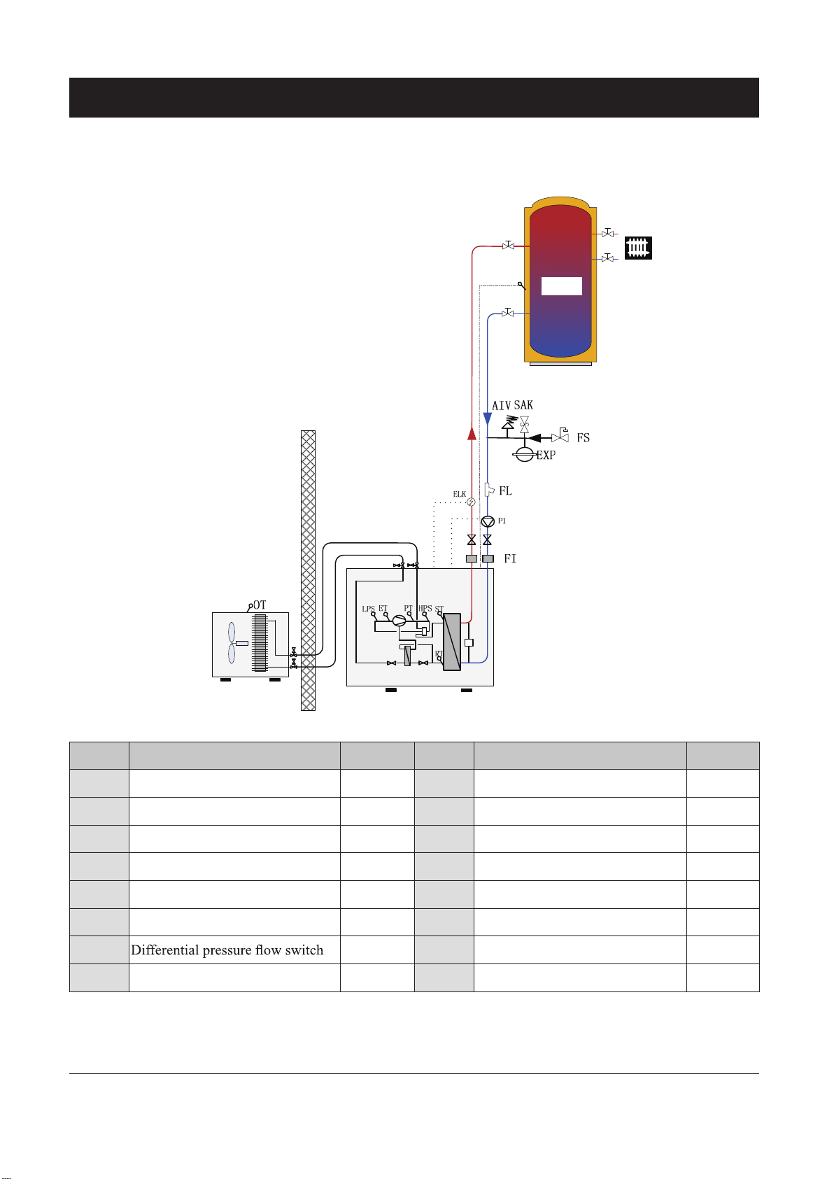
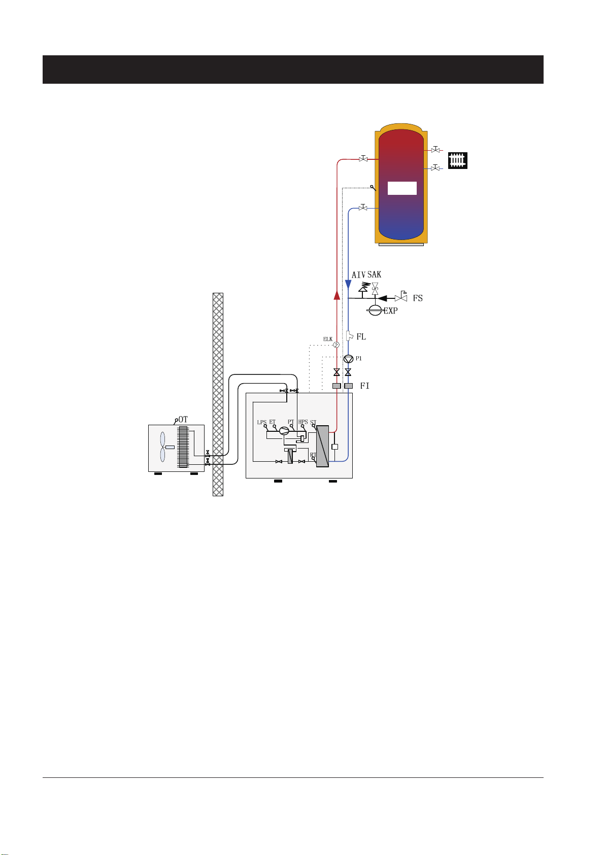
Systems Overview
Heating and Cooling ( Without internal hot water pump ,three way valve and
electric heater)
RT
Buffer tank
②
F
③
①
Outdoor unit
⑤
④
⑥
Indoor unit
Name Description Included ? Name Description Included ?
P1 Circulation pump External RT Inlet water temperature sensor Internal
ELK Electric heater External ST Outlet water temperature sensor Internal
FI Soft joint External OT Outdoor temperature sensor Internal
FS Automatic water supplement valve External LPS Electronic low pressure transmitter Internal
SAK Safety valve External HPS Electronic high pressure transmitter Internal
FL Filter External ET Suction gas temperature sensor Internal
F Internal
EXP Diaphragm expansion vessel External
AIV
Exhaust gas temperature sensor Internal
PT
Air vent valve External
9

Systems Overview
Heating Mode Working Principle:
On heating mode
a. When SF04:enable compensation=NO,
When the Inlet water temperature≤ RTc-ST04 (RTc
is the actual read Inlet water temperature of the
last stop) , the compressor will start to heat. After
outlet water temp. B2≥ST02, compressor will stop.
The Compressor will start again when Inlet water
temperature≤RTc-ST04,.
b. When SF04 enable compensation=YES,
ST02 is replaced by “Set temperature at heating”
=ST05+ST06/10 *(ST05-OT). Refer to chapter
“Heating compensation curve setting” .
Cooling Mode Working Principle:
When the Inlet water temperature B1
(RTc is the actual read inlet water temp. of last stop),
the compressor will start to cool until Outlet water
temperature B2
The Compressor will start again when Inlet water
temperature B1≥RTc+ST3.
ST01. Then compressor will stop.
≤
RTc+ST03
≥
10
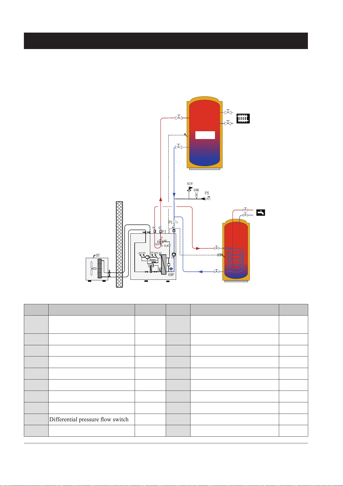
Systems Overview
Heating with hot water (with internal water pump, three way valve and electric
heater )
RT
Buffer tank
F
Outdoor unit Indoor unit
VVB
Name Description Included ? Name Description Included ?
P1 Circulation pump
Internal
RT Inlet water temperature sensor Internal
ELK Electric heater Internal ST Outlet water temperature sensor Internal
VXV 3 way Valve Internal OT Outdoor temperature sensor Internal
VVB Hot water tank External HT Hot water temperature sensor Internal
FI Soft joint External ET Suction gas temperature sensor Internal
EXP Diaphragm expansion vessel internal LPS Electronic low pressure transmitter Internal
SAK Safety valve External HPS Electronic high pressure transmitter Internal
FL Filter External PT Exhaust gas temperature sensor Internal
F
Internal FS Automatic water supplement valve External
AIV Air vent valve External
11

Systems Overview
1. Heating Mode Working Principle: 2. Hot water production working principle:
On heating mode, Three way valve (VXV) will open
AB-A.
1) When SF04 enable compensation=NO:
a. When the inlet water temp. B1 ≤ RTc-ST04, (RTc
is the actual read inlet water temp. of last stop) the
compressor will start to heat .After outlet water temp.
B2≥ST02, compressor will stop. The Compressor will
start again when inlet water temp. B1≤RTc-ST04,.
b. When the outdoor temperature Ambient temp.
B3≤ST07 ,compressor has run over 300s and Outlet
water temperature B2≤ST02-ST04-1, the electric heater
(ELK) will be activated as heating booster. It will stop
heating when Outlet water temperature B2≥ ST02-
ST04.
2) When SF04 enable compensation=YES:
ST02 is replaced by “Set temperature at heating”
=ST05+ST06 *(ST05-OT). Refer to chapter “Heating
compensation curve setting” .
On hot water mode, Three way valve (VXV) will open
AB-B.
When domestic hot water requirement calls, the three
way revert valve (VXV) will have the priority to revert
to the hot water tank (VVB). After the domestic hot
water reach its set temperature ST09, the three way
revert valve (VXV) return to its heating position. After
Hot water temp. B4≤ST09 – ST10, three way revert
valve (VXV) will revert to hot water circuit again.
12

Installation
1. The pipe installation must adhere to the local
Building Code, standards and any local council
requirements.
2. Ensure that the water ow and returns are correct and
not reversed. Reversing the water ow will reduce
the output of the unit; refer to the labels on the unit
for the correct water ow direction.
3. The water pipes must not transmit any radial or
axial forces to the heat exchanger. Allow some pipe
exibly between the unit and the structure to reduce
any stresses and vibrations issues.
4. The water supplied to the system must be clean and
not contain heavy metals that could cause harm
to the unit. The water must be treated with an
approved inhibitor and tested annually to prevent
corrosion, fouling and deterioration of the pump
ttings.
5. Protection devices are to be installed to protect the
unit from operating outside of its running parameter
such as control devices; shutoff valve, bleed valves,
safety valves and expansion tanks.
6. The pipe installation should be designed to have the
least number of elbows and joiners as they reduce
ow. Install drain connections at low points to allow
the system to be drain if required.
7. Flexible connections should be used where possible
to reduce vibration transmission.
8. Insulate all pipe work and exposed areas to protect
against both thermal heat loss and to prevent
condensation on chilled pipes.
9. When filling the water system, use air vents and
flushing procedure to evacuate any residual air
pockets.
10. The heat pump is not tted with shutoff valves and
therefore these must be fitted outside of the heat
pump to facilitate future service requirement.
13
Pipe connections
+
Indoor unit
R
8
0
5m
Oil return
curve
Outdoor unit
/
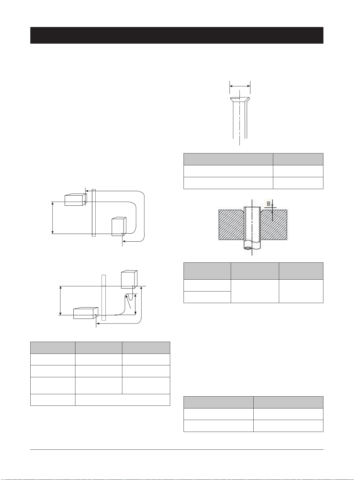
Flare connections
Connecting refrigerant pipe (not supplied)
Install the refrigerant pipes between the outdoor unit
and indoor unit.
Installation must be carried out in accordance with
current norms and directives.
· If indoor unit is higher than outdoor unit more than
5m, an oil return curve must be made in each 5m .
· Max. height difference between indoor and outdoor
unit(H):10m
· Max. pipe length (L) : 15m
Expansion:
A
Out diameter,copper pipe(mm) A(mm)
φ9.52 13.2
φ15.88 19.7
Pipe size φ9.52mm (3/8”) φ15.88mm (5/8”)
Connection Flare (3/8”) Flare (5/8”)
Minimum copper
coil thickness
Max pressure 4.5MPa
+
+
Outdoor unit
Liquid pipe Gas pipe
Indoor unit
/
Indoor unit
Oil return
curve
R
5m
8
0
1.0mm 0.8mm
Out diameter,
copper pipe(mm)
φ9.52
φ15.88
· Service valves on indoor/outdoor pipe connector
should close when connecting the pipes. The indoor/
outdoor pipe connector refer to Chapter “components”
· Ensure that water and dirt does not enter the pipes.
· Bend the pipes with as large a radius as possible (at
east R100~R150).Do not bend a pipe repeatedly. Use
a bending tool.
Connect the are connector and tighten to the following
torque.
Pipe diameter Torque
R,with an R410A
tool (mm)
0-0.5 0.7-1.3
R,with a conven-
tional tool
(mm)
14
3/8” (φ9.52mm) 35-40 (N·m)
5/8” (φ15.88mm) 60-65 (N·m)
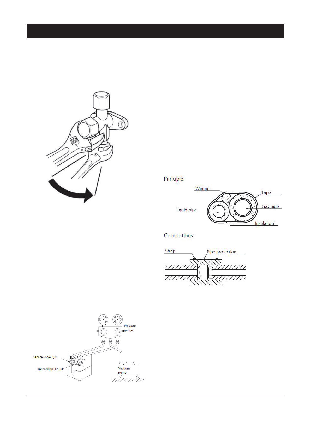
Pipe connections
· Aim the are connection of copper coil at the center of
screw connection of heat pump , screw the are nut
as tightly as possible manually.
· Tighten the are nut to required torque with a torque
wrench
Filling refrigerant:
After nishing pipe connections, pressure test ,leak test
and vacuuming, the service valves can be opened.
The gas inside the indoor unit is enough for 5m pipe.
If connection pipe is longer than 5m, need to re-fill
some R410A refrigerant. Filling weight is 50g per extra
meter.
Insulating refrigerant pipes
Insulate refrigerant pipes for heat insulation and to
prevent condensate.
Use insulation that can withstand at least 120℃.
The insulation should be at least 13 mm think.
Pressure test and leak test
The pipe connection between indoor and outdoor unit
must be pressure tested and leak tested after installation.
Only nitrogen could be used when pressurizing and
ushing the system.
Use a vacuum pump to evacuate all air .Vacuum for at
least one hour and end pressure after evacuation must
be 1mbar absolute pressure.
If the system has remaining moisture or a leak, the
vacuum pressure will rise after completed evacuation.
NOTE!
The pipe work must be ushed before the heat pump
is connected, so that any contaminants do not damage
the components parts.
The water pressure in the heat exchanger can not
exceed 0.5Mpa.
15
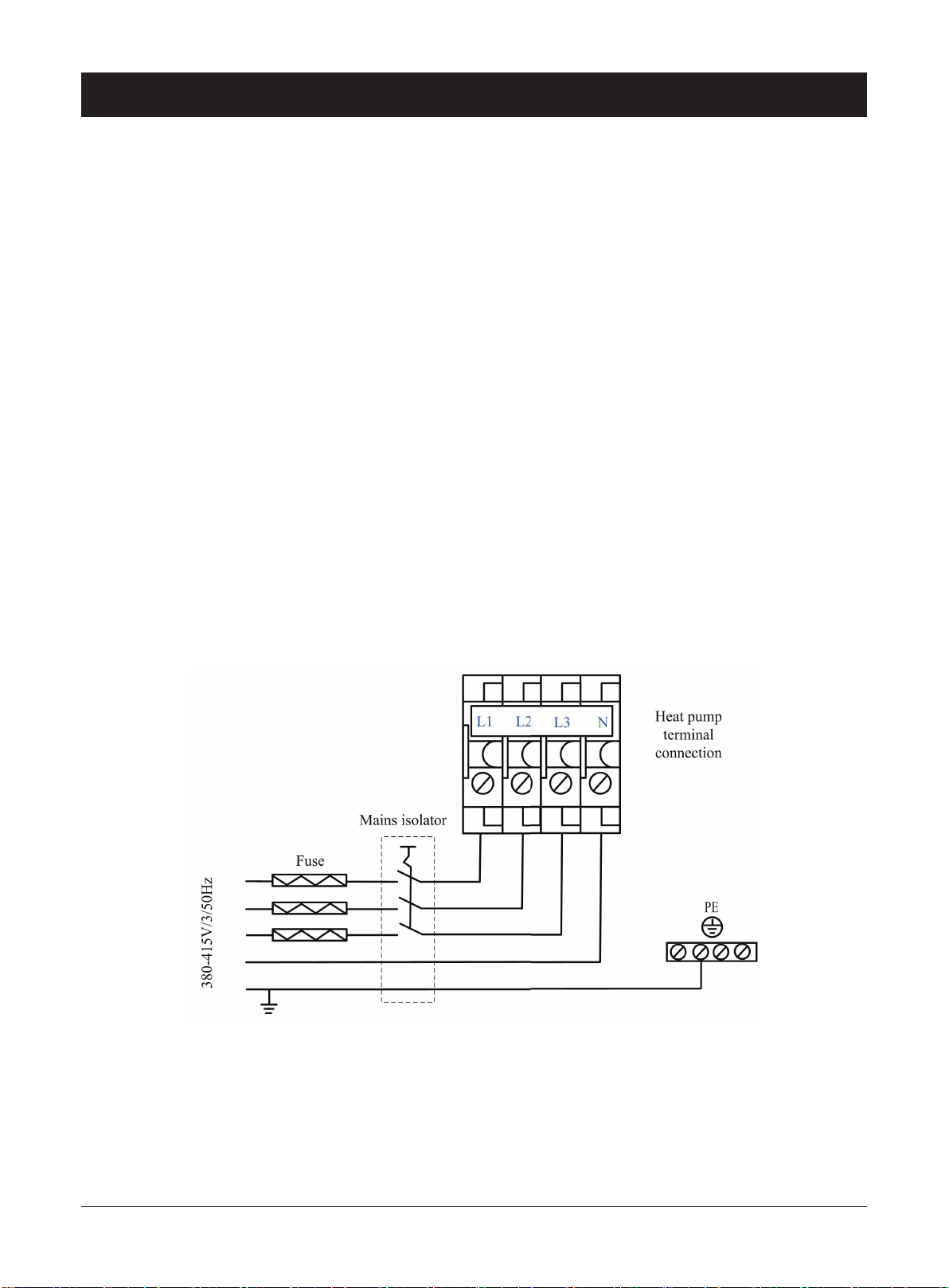
Power Connection
Electrical Connections
Before connecting the power supply, please conrm the
unit suits the power supply.
Breaker protection must be installed according to
the max value stated in the nameplate attached to
the unit inside of the front panel.
The equipment must be installed via an isolator
switch with a minimum breaking gap of 3 mm
The power supply must conform to the specication
on the unit’s nameplate. The supply voltage must
be within the range specied in the electrical data
table. For wiring connection, refer to the electric
wiring diagram on the inside panel of the unit.
When the building is equipped with a RCD the heat
pump should be equipped with a separate one
.
.
IMPORTANT:
During the installation of the unit, first make the
water connections and then electrical connections.
If the unit is to be removed first disconnect the
electrical connections, then the water connections to
reduce the chance of an electrical shock.
WARNING:
Disconnect the main power supply switch before
servicing the system or handling any internal parts
of the unit.
In case of any major malfunction turn the unit off,
disconnect the mains power supply and contact a
qualied service engineer.
16
Electrical connection
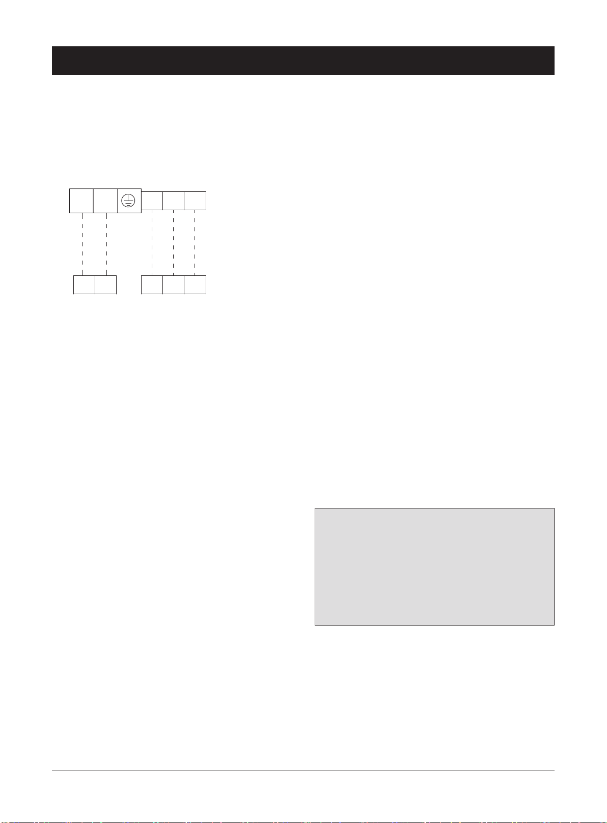
Connecting indoor and outdoor unit
Use cable (not less than 1.5m
connect indoor and outdoor unit via control board
terminal connection .
L N
345
LN 34 5
2)
(not supplied) to
Outdoor unit
Indoor unit
Note:
Outdoor unit must be earthed before the wiring before
the unit is connected.
The wiring must be attached so that the terminal block
is not under stress
Connect Outdoor ambient temperature
sensor OT (6m) (B3)
One section of OT probe (B3) is inside the outdoor unit
control box. Other section of OT probe is inside the
indoor unit control box. Connect two section of OT
probe with its connector.
Important: Temperature sensor must be separated
(min 20 cm) from high voltage power cables to
avoid interference which will cause read temperature
uctuating and heat pump can not work normally.
If the temperature sensor cable runs close to power
cables,shielded cable should be used .If a conduit is
used, it should be sealed to avoid condensation in the
outdoor temperature sensor probe
.
Indoor Side Inlet Water Temperature
Sensor:
The indoor side inlet water sensor (B1) from factory is
placed at inlet water pipe.
If a buffer tank is installed, the Inlet water temperature
sensor B1 can be moved to the buffer tank temperature
sensor inlet pocket and EV01 parameter value can
be set to “work by regulation”. This stops the pump
running when compressor is OFF.
If the Inlet water temperature sensor B1 can not be
moved to the buffer tank temperature sensor inlet,
the EV01 parameter value must be set to “continuous
work” (factory default setting). This allows the pump
to continue to run so Inlet water temperature sensor B1
read the same as butter tank water temperature.
Important:
Temperature sensor for hot water:
The hot water sensor (B4) is connected to terminal
positions B4 and GND on the main board, the other
terminal must be put into hot water cylinder temperature
sensor probe inlet pocket if required.
If the hot water sensor cable runs close to power cables,
then a shielded cable should be used. If a conduit is
used then it should be sealed to avoid condensation
forming in the temperature sensor probe
.
All temperature sensor must be separated (min
200 mm) from high voltage power cables to avoid
interference which will cause read temperature
fluctuating and the heat pump may operate
incorrectly.
17
 Loading...