

HIS HIS-ML19-***E User Manual
19" PANEL MOUNT INDUSTRIAL MONITOR
USER MANUAL
Model No. HIS-ML19- _ _ _ E
REVISION E

2 ML19E User Manual, February 2011
Table of Contents
Safety and Regulatory Information ��������������������������������������������������������������������������������3
FCC Notice ����������������������������������������������������������������������������������������������������������������������������� 3
Hazardous Locations ��������������������������������������������������������������������������������������������������������������4
Waste Electrical and Electronic Equipment Directive (WEEE) �����������������������������������������������4
Mechanical Drawings ������������������������������������������������������������������������������������������������������5
Front and Side Views �������������������������������������������������������������������������������������������������������������� 5
Bottom View ���������������������������������������������������������������������������������������������������������������������������� 5
Installation Instructions ��������������������������������������������������������������������������������������������������6
Step 1: Prepare for Installation ���������������������������������������������������������������������������������������������� 6
Step 2: Bench-test Conguration ������������������������������������������������������������������������������������������� 7
Install Cable Connections ������������������������������������������������������������������������������������������������������������������ 7
Install Touchscreen ���������������������������������������������������������������������������������������������������������������������������� 8
Step 3: Install into Panel ������������������������������������������������������������������������������������������������������ 10
Video Settings ����������������������������������������������������������������������������������������������������������������12
Setting the Timing Mode ������������������������������������������������������������������������������������������������������� 12
Control Panel Buttons �����������������������������������������������������������������������������������������������������������13
OSD and Power Lock Settings ��������������������������������������������������������������������������������������������� 14
On-Screen Display (OSD) Menus ����������������������������������������������������������������������������������������� 15
Auto Image Adjust Menu ������������������������������������������������������������������������������������������������������������������ 16
Contrast / Brightness Menu�������������������������������������������������������������������������������������������������������������� 16
Input Select Menu ���������������������������������������������������������������������������������������������������������������������������� 16
Color Adjust Menu ���������������������������������������������������������������������������������������������������������������������������� 17
Information Menu ����������������������������������������������������������������������������������������������������������������������������� 18
Manual Image Adjust Menu�������������������������������������������������������������������������������������������������������������� 18
Setup Menu �������������������������������������������������������������������������������������������������������������������������������������� 19
Memory Recall Menu ����������������������������������������������������������������������������������������������������������������������� 19
Cleaning Instructions ����������������������������������������������������������������������������������������������������20
Troubleshooting ������������������������������������������������������������������������������������������������������������21
Video Troubleshooting ����������������������������������������������������������������������������������������������������������21
Touchscreen Troubleshooting ����������������������������������������������������������������������������������������������� 23
Specications ����������������������������������������������������������������������������������������������������������������24
Display ����������������������������������������������������������������������������������������������������������������������������������24
Environmental �����������������������������������������������������������������������������������������������������������������������24
Video ������������������������������������������������������������������������������������������������������������������������������������� 25
Electrical ������������������������������������������������������������������������������������������������������������������������������� 25
Functional ����������������������������������������������������������������������������������������������������������������������������� 25
Physical ��������������������������������������������������������������������������������������������������������������������������������26
Compliances and Certications �������������������������������������������������������������������������������������������� 26
Warranty Statement �������������������������������������������������������������������������������������������������������27

Safety and Regulatory Information
ML19E User Manual, February 2011 3
To prevent re or shock hazard, do not expose live components to rain or moisture�
Dangerously high voltages are present inside the unit� Do not disassemble the unit�
Refer servicing to qualied personnel only�
This equipment is not intended for use in critical applications where its failure
to operate would create immediate life threatening circumstances� Applications
including, but not limited to, nuclear reactor control, aerospace navigation systems
and life support systems are not appropriate for this product�
This product is intended to be mounted in a suitable cabinet or other enclosure�
The NEMA 4, 4X, or 12 ratings are applicable only when properly installed in a like
rated enclosure�
To be covered by UL 60950 3rd Edition, the socket-outlet shall be installed near the
equipment and shall be easily accessible�
FCC Notice
This equipment has been tested and found to comply with the limits for a Class A digital
device, pursuant to Part 15 of the FCC Rules� These limits are designed to provide
reasonable protection against harmful interference when the equipment is operated
in a commercial environment� This equipment generates, uses, and can radiate radio
frequency energy and, if not installed and used in accordance with the instruction manual,
may cause harmful interference to radio communications� Operation of this equipment
in a residential area is likely to cause harmful interference in which case the user will be
required to correct the interference at his own expense� Any changes or modications not
expressly approved by the grantee of this device could void the user’s authority to operate
the device�
Safety and Regulatory Information
WARNING!
!

Safety and Regulatory Information
4 ML19E User Manual, February 2011
Hazardous Locations
The following applies only to monitors rated for hazardous locations (model
numbers HIS-ML19-
_ _
HE):
This equipment is suitable for use in Class I, II & III, Division 2, Groups A, B, C, D, F, and G
or non-hazardous locations only�
WARNING – EXPLOSION HAZARD – Do not disconnect equipment unless power has
been removed or the area is known to be non-hazardous�
WARNING – EXPLOSION HAZARD – Substitution of any components may impair
suitability for Class I, II & III, Division 2 Locations�
Waste Electrical and Electronic Equipment Directive (WEEE)
The following information is only for EU-member states:
The mark shown to the right is in compliance with the Waste Electrical and
Electronic Equipment Directive 2002/96/EC (WEEE)�
The mark indicates the requirement NOT to dispose of the equipment as unsorted
municipal waste, but use the return and collection systems according to local law� Users
should contact their supplier and check the terms and conditions of the purchase contract�
When purchased directly from Hope Industrial Systems, you may contact technical support
for disposal arrangements�
Mechanical Drawings
ML19E User Manual, February 2011 5
Mechanical Drawings
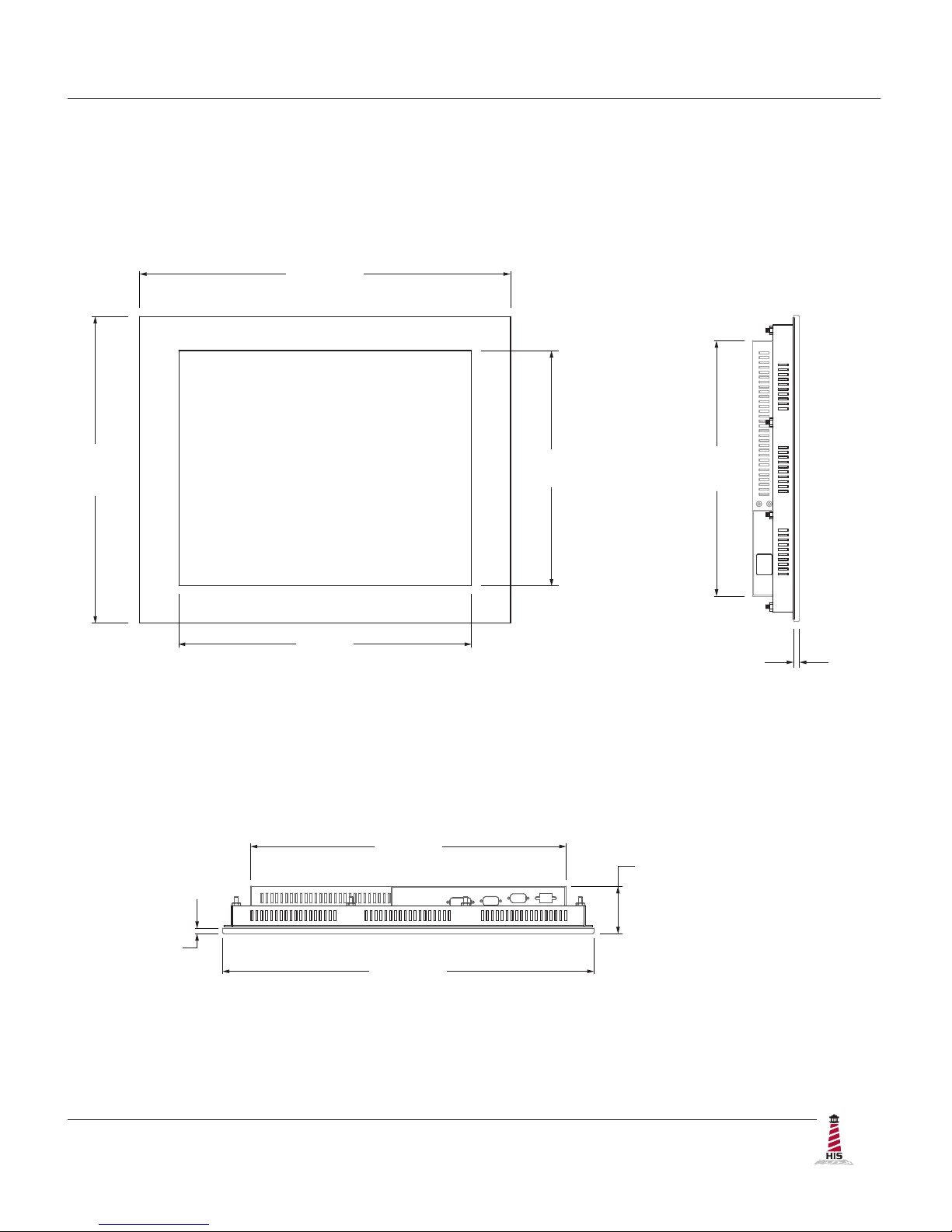
Front and Side Views
Bottom View
332.8 mm
(13.10")
7.1 mm
(0.28")
398.8 mm
(15.70")
482.6 mm
(19.00")
376 mm
(14.8")
301 mm
(11.9")
61.6 mm
(2.43")
409.8 mm
(16.14")
482.6 mm
(19.00")
7.1 mm
(0.28")
(Design to maximum depth
of 69.0 mm to ensure future
compatibility with later revisions
and replacement units.)
Installation Instructions
6 ML19E User Manual, February 2011
Installation Instructions
Step 1: Prepare for Installation
IMPORTANT!
Perform the following steps BEFORE installation of the monitor into the panel�
1� Ensure that sufcient power is available�
2� Ensure that sufcient space is available to allow for proper air ow into and out of the
unit�
3� Ensure that the air temperature around the unit (top and bottom) will not exceed the
rated specications of the unit.
f The maximum rated temperature for the HIS-ML19 is 50°C (122°F)�
f Remember that heat rises – the temperature at the top of the
cabinet will be much hotter than at the bottom if air inside the
enclosure is not actively circulating� Even in a sealed enclosure,
use of a circulation fan can greatly reduce temperature�
f Also, remember that even though this product is designed to
operate at 50°C, the life span of any electronic device is shortened
when it is consistently operated at high temperatures� Therefore,
it is wise to take steps to keep the temperature of the ambient air
around the unit as low as possible�
4� Ensure that the ambient humidity of the air around the unit does not exceed the
specications of the unit.
f The maximum rated humidity for the HIS-ML19 is 90%
non-condensing�
!
Installation Instructions
ML19E User Manual, February 2011 7
Step 2: Bench-test Conguration
Make sure everything works before installing into the production environment�
TIP!
Install Cable Connections
All monitors are shipped with both a 6 ft� VGA video cable and 6 ft� power cable, unless longer
cables were ordered in their place� If you ordered a touchscreen monitor, you also received a 6
ft� Serial (RS-232) cable and 6 ft� USB cable�
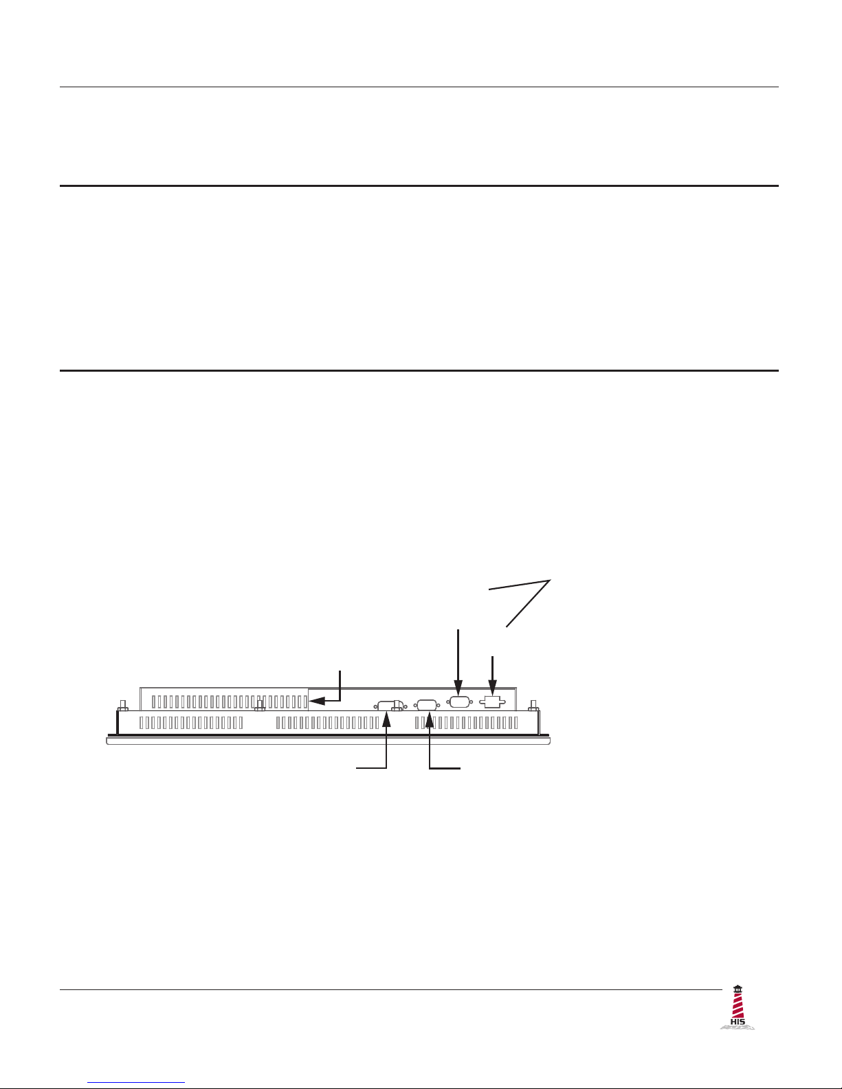
The cable ports are located on the rear of the monitor� Refer to the following diagram and
instructions to connect power, video, and touchscreen (if applicable) to your monitor�
If using a KVM extender, please refer to the installation instructions included with the
KVM extender module� It is particularly important to bench-test the full conguration
prior to nal installation� This will help to identify and troubleshoot any system issues
while conguration changes may still be easily made�
Video Connection
The HIS-ML19 supports analog and digital video�
Analog Video Connection
Connect one end of the VGA video cable to the HD-15 input port on the rear of the
monitor� Connect the other end to the analog video output port on the host computer�
DIGITAL VIDEO
USB
(for Touchscreen option)
SERIAL
(RS-232)
POWER INPUT
ANALOG VIDEO

Installation Instructions
8 ML19E User Manual, February 2011
Digital Video Connection
Connect one end of the DVI video cable to the DVI-D input port on the rear of the
monitor� Connect the other end to the digital video output port on the host computer�
Power Connection
The HIS-ML19 is powered by 120/240 VAC, 1�2/0�6 A, 60/50 Hz�
Connect the AC power cable to the power input port on the rear of the monitor� Connect the other
end into a nearby outlet�
Install Touchscreen
Applies to touchscreen monitors only� Instructions below apply to Windows systems� Both Serial
and USB ports are present on all touchscreen monitors, but only one should be used to connect
the touchscreen interface to the monitor�
All touchscreen monitors are shipped with a CD-ROM that contains documentation and drivers for
all major operating systems� To be sure that you have the most current information, please check
the following Internet address:
http://www�HopeIndustrial�com/Touchscreen_Drivers�htm
IMPORTANT!
If you will be using a Serial connection, connect the Serial cable rst, and then
install the touchscreen driver� If you will be using a USB connection, install the
touchscreen driver rst, and then connect the USB cable�
Serial (RS-232) Connection
1� Connect one end of the Serial cable to the Serial input port on the rear of the monitor�
Connect the other end to the Serial port on the host computer� Tighten the captive
screws on the cable connectors to ensure adequate strain relief�

Installation Instructions
ML19E User Manual, February 2011 9
2� Select the appropriate driver for your operating system�
a� If downloading from the web address listed above, select the appropriate
driver for your operating system�
b� If using the included CD, insert it into the host computer's CD-ROM drive� If
the CD does not automatically run, browse the contents of the CD and open
the ReadMe�htm le in a web browser� Select the appropriate driver�
NOTE: For Windows 7 and Vista operating systems, you must save the driver to
a location on your hard drive, then run using elevated privileges by right-clicking
on the le and selecting "Run as administrator"�
3� Click to "Run" the software when prompted� Follow on-screen instructions to
download and execute the touchscreen driver installation�
USB Connection
1� Select the appropriate driver for your operating system�
a� If downloading from the web address listed above, select the appropriate
driver for your operating system�
b� If using the included CD, insert it into the host computer's CD-ROM drive� If
the CD does not automatically run, browse the contents of the CD and open
the ReadMe�htm le in a web browser� Select the appropriate driver�
NOTE: For Windows 7 and Vista operating systems, you must save the driver to
a location on your hard drive, then run using elevated privileges by right-clicking
on the le and selecting "Run as administrator"�
2� Click to "Run" the software when prompted� Follow on-screen instructions to
download and execute the touchscreen driver installation�
3� A cable retention bracket comes installed on the USB port on the rear of the monitor
and will help to secure the cable and ensure adequate strain relief� Route one end of
the USB cable through the retention bracket and connect it to the USB input port on
the monitor� Connect the other end to the USB port on the host computer�
Calibrate the Touchscreen
Once the driver has nished installing, you are ready to calibrate the touchscreen� Open the
touchscreen's Control Panel, located in the host computer's Control Panel�
NOTE: The latest versions of Windows touchscreen drivers provided by Hope Industrial have an
"Enhanced Calibration Mode" option� If applicable to your particular driver, this setting may be
found in the touchscreen's Control Panel under the "Mode" tab�
 Loading...