

Hirth 2704 Service Manual
Göbler-Hirthmotoren KG
Service manual
Engine
2704
Göbler-Hirthmotoren KG, Max-Eyth-Str. 10, D-71726 Benningen, Germany
Tel.: 0049-7144-8551-0, Fax: 0049-7144-5415
e-mail: info@hirth-engines.de, internet: www.hirth-engines.de

Engine
Type 2704
Manual
Read the operating instructions completely before the assembly of the
engine or before starting the engine.
In the interest of the ongoing developments of our products, we
reserve the right to change the delivery volume in form, technique and
supply. We also ask for your understanding that the data in this
instruction manual gives no further claims.

Table of Contents
Chapter Topic Page
1 Description of the engine, its systems, and 1-1
essential technical information
1.1 Overview of the engine 1-1
1.1.1 Model 2704 1-1
1.1.2 Description of the carburetion system 1-2
1.1.3 Description of the ignition system 1-2
1.1.4 Description of the cooling system 1-4
1.2 Installation 1-4
1.2.1 Mounting and securing the engine 1-4
1.2.2 Airflow to the engine 1-5
1.2.3 Fuel system layout 1-5
1.2.4 Adjusting the carburetors 1-6
1.2.5 Securing spark plug caps: Inverted installation 1-6
1.2.6 Disconnecting ignition system 1-6
1.3 Engine instruments 1-7
1.3.1 Cylinder head temperatures 1-7
1.3.2 Exhaust gas temperature 1-7
1.3.3 Fuel pressure 1-8
1.4 Identification plate 1-8
1.5 Technical data 1-9
1.6 Installation sketch 1-9
2 Operating the engine 2-1
2.1 General guidelines 2-1
2.2 Engine break in 2-1
2.3 Starting procedures 2-2
2.4 Operating conditions 2-3
2.5 Engine shutdown 2-3

3 Maintenance 3-1
3.1 General 3-1
3.1.1 Scope 3-1
3.1.2 Common and special tools and initial torque values 3-1
3.2 Service intervals 3-2
3.2.1 Daily inspections 3-2
3.2.2 Periodic inspections 3-2
3.3 Replacement parts 3-2
3.4 Maintenance procedures 3-3
3.4.1 Carburetor 3-3
3.4.1.1 Synchronization of carburetors 3-3
3.4.1.2 Setting the fuel mixture adjustment screws 3-3
3.4.1.3 Cleaning the carburetors 3-4
3.4.2. Air filter 3-4
3.4.2.1 Removal and installation of air filters 3-4
3.4.2.2 Cleaning the air filters 3-4
3.4.3 Fuel and pulse lines 3-4
3.4.3.1 Inspection of fuel line 3-4
3.4.3.2 Inspection of pulse line 3-4
3.4.4 Spark plugs and spark plug caps 3-4
3.4.4.1 Checking spark plug caps 3-4
3.4.4.2 Spark plug installation and removal 3-5
3.4.4.3 Condition of spark plugs 3-5
3.4.5 Fan 3-5
3.4.5.1 Removal and installation of cooling system 3-5
3.4.5.2 Removal and installation of fan housing 3-5
3.4.5.3 Changing the fan belt 3-5
3.4.6 Cylinder head 3-6
3.4.6.1 Removal and installation of cylinder head 3-6
3.4.6.2 Checking cylinder head conditions 3-6
3.7 Trouble shooting 3-6
3.7.1 Engine will not start, or is very difficult to start 3-6
3.7.2 Engine will not come up to idle speed 3-7
3.7.3 Engine runs rough, uneven and with insufficient ... 3-7

3.7.4 Engine does not develop full power 3-7
3.7.5 Excessive cylinder head temperature 3-8
4. Ignition system wiring diagrams 4-1
4.1 Single ignition wiring diagram 4-2
4.2 Dual ignition wiring diagram 4-3
Chapter 1
Description of the Engine, Its Systems, and Essential Technical Data
1.1 Overview
1.1.1 Model 2704
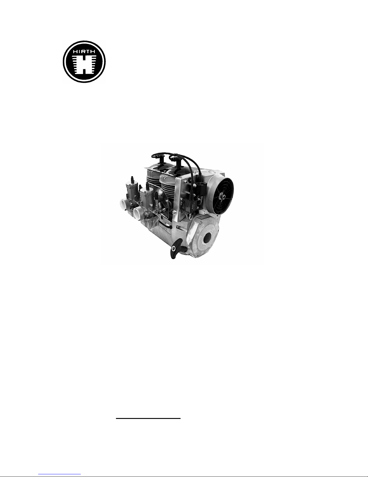
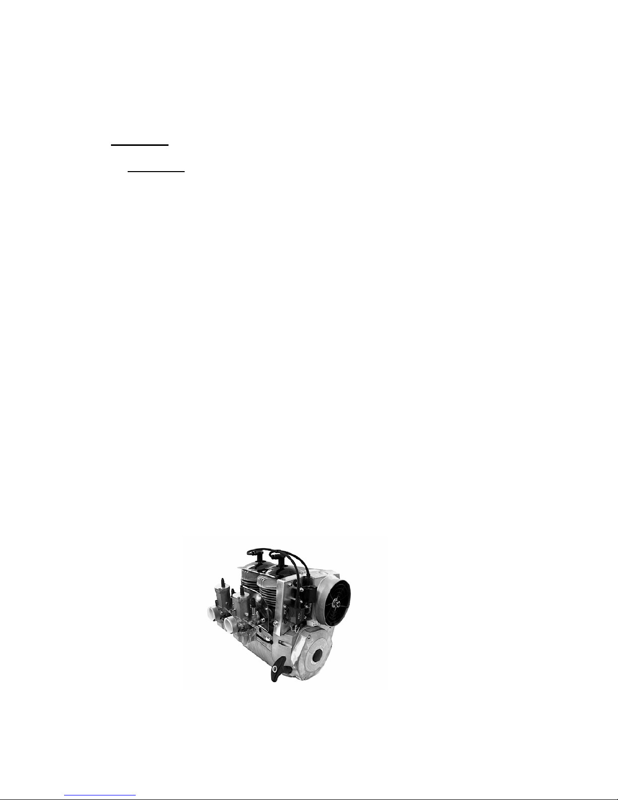
The Hirth 2704 engine (Illus. 1.1.1-1) from Göbler-Hirth Engines Ltd., is a fan-cooled, sideregulated, two-cylinder inline, two-stroke engine.
The cylinders consist of an aluminium alloy coated with an abrasion-resistant surface. The
cylinders are attached to the crankcase with bolts, washers and hexagonal nuts. The cylinder
heads consist of a special non-melting aluminium alloy, which resists high temperature with
an even hardness. They are fastened to the cylinder without any sealant, using cylinder bolts
and washers.
The pistons consist of an aluminium alloy and are packed with two piston rings against the
cylinder surface. The piston is connected to a piston rod with a gudgeoned pin and needle
roller bearing.
The crankshaft is made of Chromoly steel (42CrMo4) and is positioned in five grooved ball
bearings. It is a constructed crankshaft in which the individual parts are pressed together to
form the complete crankshaft. Two grooved ball bearings are attached on the power take off
side, two more between the crank control handle, and one on the ignition side. The power take
off is cone-shaped and has a centric coil in order to wind a connecting cone onto the power
take off side. The piston rods are connected to the crankshaft with crank pins and needle roller
bearings.
The crankcase consists of an aluminium alloy. It is constructed as an axial divided case and
consists of a lower and an upper part. It is held together by three cylinder bolts with safety
washers, and in addition by the eight fastening bolts of the cylinders. On the ignition side, it
includes the stator plate of the ignition and is constructed so that the fan housing can be
mounted over it.
Illustration 1.1.1-1 (Engine 2704 two carburettor)
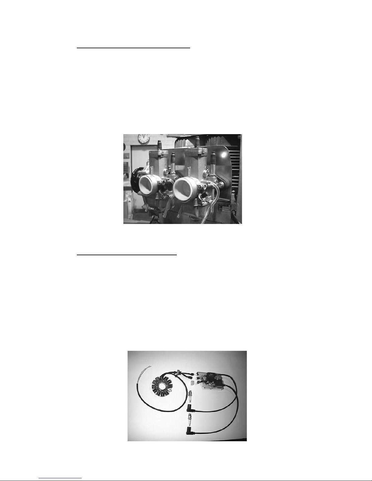
1.1.2 Description of the Carburetion System
The fuel mixture system (Illus. 1.1.2-1) of the 2704 engine consists of one or two carburettors.
Each carburettor is connected to the entry port of the cylinder by an aluminium intake socket
and a rubber flange. The aluminium intake socket is screwed on to the cylinder with cylinder
bolts and lock washers and the carburettor is secured in the rubber flange by a hose clamp.
The carburettor is thermally neutralized by a piece of insulation. The hot cool air stream
exiting from the intake socket is kept apart from the carburettor by shield in the intake socket.
On the intake side of the carburettors are one or two dry air filters.
Illustration 1.1.2-1 (Fuel Mixture [or Carburetion] System)
1.1.3 Description of the Ignition System
The ignition system (Illus. 1.1.3-1, 1.1.3-2) consists of an armature plate, a magneto, an EBox, two ignition coils and the ignition cables with spark plug caps. The ignition is entirely
electronic and has an e-prom for a free programmable electro-dynamo-magnetic ignition.
There is generator power for electric uses during operation and for charging the battery. The
ignition system is operational with single as well as double ignition. The armature is fastened
to the crankcase on the ignition side. The magneto is situated on the crankshaft and encloses
the armature plate. The fan housing shields the magneto wheel of the ignition. On the fan
housing is the E-Box and the ignition coils on an ignition coil fastener.
Illustration 1.1.3-1 (Single Ignition)

Illustration 1.1.3-2 (Dual Ignition)
Illustration 1.1.3-3 (View of the ignition side with installed ignition system)
1.1.4 Description of the Cooling System
The 2704 engine has a mechanically operated forced air-cooling, which is transposed on the
exhaust side and fixed on the ignition side. (Illus. 1.1.4-1).
The fan is mounted inside the fan housing by a cam. It is propelled by a flat belt and a catch,
which is attached to the magneto wheel of the ignition.
The cool airflow, built up by the fan, is divided over the two cylinders for maximum cooling
through the fan shroud surrounding the two cylinders. The hot cool airflow is blown off into
the surroundings on the intake side.
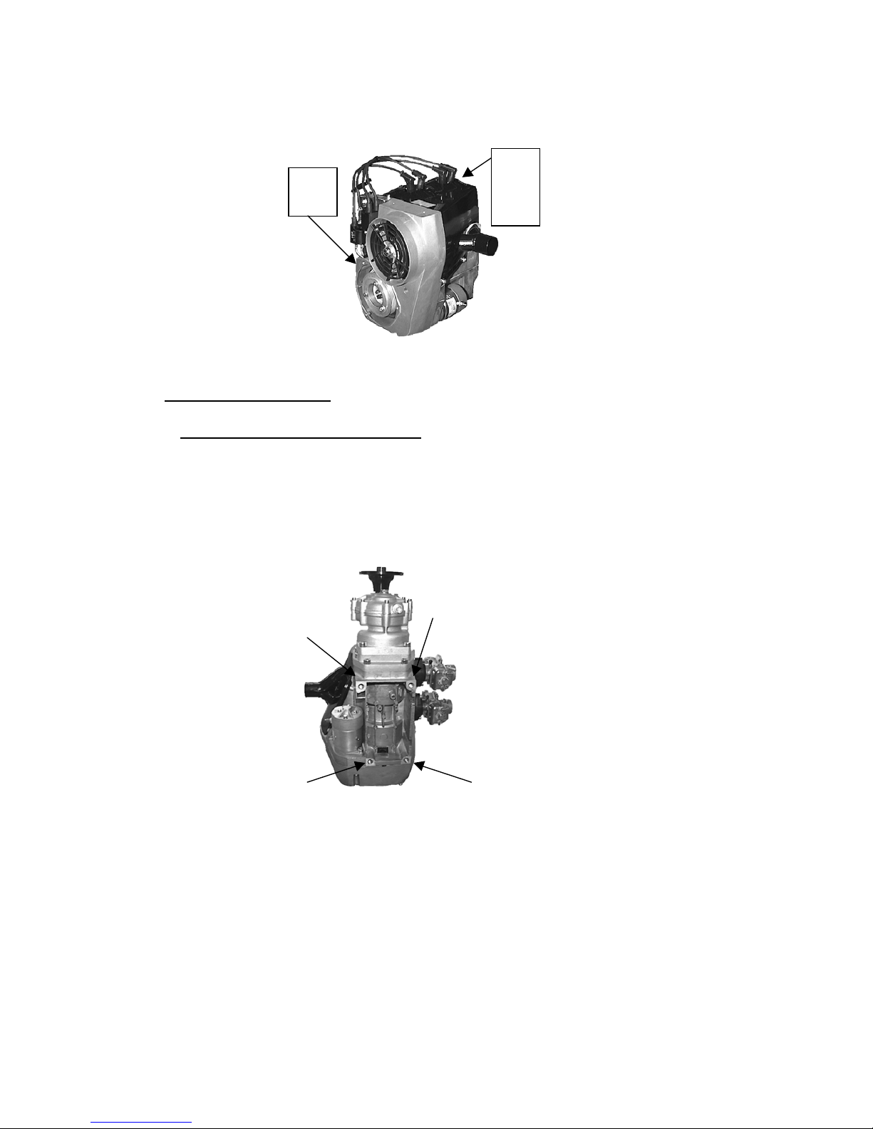
Illustration 1.1.4-1 (View of the Fan Housing and the Shroud)
1.2 Installation Instructions
1.2.1 Mounting and Securing the Engine
The four threaded sockets (UNC- ½“) for mounting the 2704 engine (Illus. 1.2.1-1) are
located on the underside of the crankcase.
Illus. 1.2.1-1 (Engine Mounting Sockets)
The engine should be mounted so that the moment transmitted from the engine to the mount
can be on the broadest base as possible. The shock mounts used should be as stiff as possible,
because the engine vibration can result in a mounting that is not secure. This leads to
problems with the fuel mixture (i.e. foaming of the fuel, uncontrolled flapping of the fuel
pump membrane) and with that to unsafe operation of the engine.
-Recommendation:
The engine is bolted to a plate that is about twice the size as the underside of the engine (the
wider the better). On the two outsides of the plates, there should be six or more rubber
dampeners, three on each side, in line. This entire assembly will be fastened through the
rubber dampener elements onto another plate that in turn is tightly connected to the apparatus.
Air buffling
cowl
Fanhousing
 Loading...