

Hirth 210R, 220R, 171R, 211R Assembly Instructions Manual
Two
Cylinder
Engine
Models
'
210R
-Instructions-
Assembly
lntructlons
pour
• 211R •
and
le
Montage
220R
• 171R
Disassembly
et
Demontage
du
Moteur
ISSUE MM-331
~~
SALES
TEL
AND
SERVICE
F
MILWAUKEE,
REPRESENTATIVES
WISCONSIN
WISCONSIN
53246
FOR
MOTOR
HIRTH
ENGINES
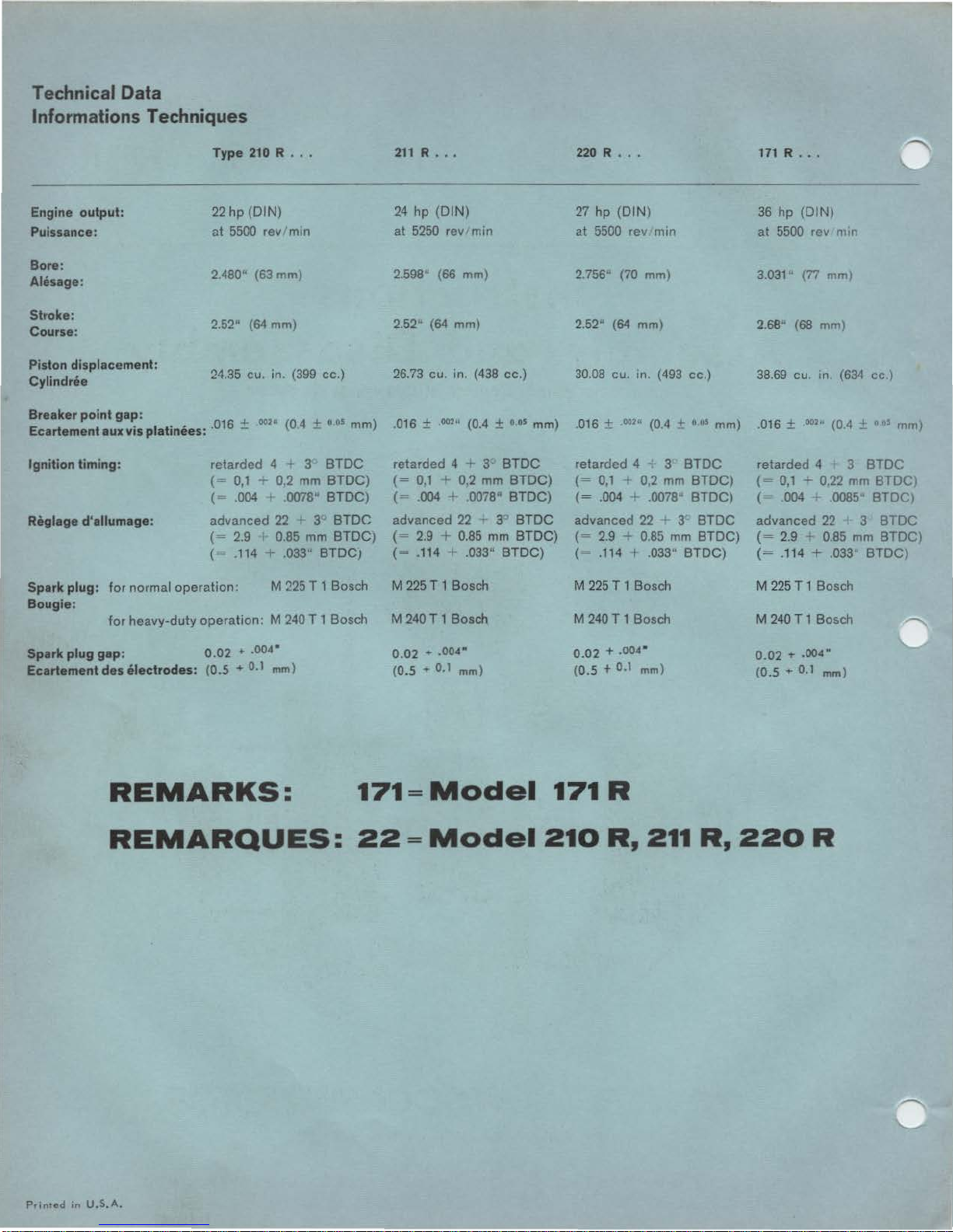
Technical Data
Informations Techniques
Type
210 R ..•
Engine
output:
22
hp
(DIN)
Puissance:
nt
5500 rev 'min
Bore:
2.480" (63 mm)
Ah'lsage:
Stroke:
2.52" (64 mm)
Course:
Piston displacement:
24.35 cu. in. (399 cc.)
Cylindree
Breaker
point
gap:
+ .
oo
2
11
(O
+
o.os
)
Ecartementaux
vis platinees: ·
016
- 4 -
mm
Ignition
timing:
Reglage d'allumage:
retarded
4 + 3
BTDC
(=
0,1 - 0,2 mm
BTDC)
(= .004 r .0078"
BTDC)
advanced
22
I 3"
BTDC
(=
2.9 0.85
mm
BTDC)
(= .114 + .033" BTDCJ
Spark
plug:
for
normal operation:
M
225 T 1 Bosch
Bougie:
for
heavy-duty operation. M 240 T 1 Bosch
Spark
plug
gap:
0.02
...
004"
Ecartement
des
electrodes:
(0.5
...
0.1
mm)
211 R ••.
220 R ••.
171 R ...
24 hp (DIN)
27
hp
{DIN)
36 hp
(DIN)
at
5250 rev min
at
5500 rev min
at
5500 rev m m
2.598"
(66 mm) 2.756·· (70 mm)
3.031" (77 mm)
2.52" (64 mm)
2.52u (64 mm)
2.68" {68 mm)
26.73 cu. in. (438 cc.)
30.08 cu.
m.
(493 cc.)
38.69 cu. in (634
cc
.)
.016 ±
002
"
(0.4 ±
0
05
mm)
.016 ± 00211 (0.4 ±
CIIIS
mm)
.016 ±
002
" (0.4 ± "
11
5
mm)
retarded
4 + 3"
BTDC
retarded 4 + 3
BTDC
retarded 4 3
BTDC
{=
0,1 + 0,2
mm
BTDC)
{=
0,1 + 0.2
mm
BTDC)
(=
0,1 - 0,22
mm
BTDC
}
{=
.004 + .0078" BTDC)
(=
.004 + .0078"
BTDC)
(=
004
-r
.0085"
BTDC)
advanced 22
-r
3
BTDC
advanced 22 ... 3
BTDC
advanced 22 3
BTDC
(=
2.9
.....
0.85
mm
BTDC)
(=
2.9 + 0.85
mm
BTDC)
{=
2.9
0.85
mm
BTDC)
(=
.114 ......
033
11
BTDC)
(=
.114 t .033"
BTDC)
(=
.114 + .033"
BTDC)
M 225 T 1 Bosch M 225 T 1 Bosch M 225 T 1 Bosch
M
240 T 1 Bosch M 240 T 1 Bosch M 240 T 1 Bosch
0.02
+ .004"
0.02
+ .004"
0.02
'r
.004"
(0.5 + 0.1
mm)
(0.5 + 0.1
mm)
(0.5
+ 0.1 mm)
REMARKS:
171 = Model
171
R
REMARQUES:
22
=
Model
210
R,
211
R,
220
R
Printed
in
U.S.A.

Disassembly of motor
Remove
motor
from apparatus Remove attached
parts,
like
exhaust silencer, corburetor,
electric
starter
etc.
2.
Screw assembly angle
1ron
W 115 into the base tap holes
and put
motor
with angle
1ron
into the vise
(fig
1)
Fan housing
3.
Lift
fan housing
with
attached
recoil
starter
after unfastening
the
fill.
head screws
(4
type
22,
6 type 171)
with
special hex
spanner 5
DIN
911.
Guide
plates
4. Pull
off
spark plug hood
w1th
protecting
cap
from spark plug.
Screw
off
the two hex. screws
with which the
ignition
cable
is
held on the
guide
plate
. Loosen
all set screws
with
which the
gui
de
plates and the exhaust manifold
are
fastened.
Take
off
intake mamfold
(for
K wrench and socket
wrench
SW
13;
SW
= width
of
wrench in mm).
171: Remove the 4 studs
for
fastening
of
the exhaust
manifold, e.
g.
by means
of
2 hex. nuts, turned
against each other, so
that
the guide plate. lying
behind, can be taken off.
Cylinders
and
pis
tons
5. 22:
Lift
off
the
two
cylinder
heads
with
cylinder
head
gasket
after
loosening the 8 fill. head screws
of
each.
Screw
off
the 8 hex. nuts with which
the
cylinders
a
re
fastened
to
the crankcase. (annular wrench
sw
13
).
171:
Lift
off
the 2
cylinder
heads
with
cylinder
head
gaskets after loosening the
four
hex. screws
(SW
5)
and the
four
hex. nuts
(SW
13).
Before
disassembly mark cylinders and the pistons
belonging
to
them with I (ignition side) and II (drive
si
de)
so
that
the parts cannot be interchanged when
they are used again.
L1ft
off
both
cylinders with cylinder
bottom
gaskets.
Take
off
the gudgeon
pin
guard.
First
disassemble
piston
of
cylinder
II . Press
out
gudgeon
pin
with
assembly pin W 39/4 from
drive
side towards
igni-
tio
n side.
If
necessary
top
lightly
with
hammer, pressing
hand against piston.
171: Disassemble piston
of
cy-
linder
I correspondingly. Push
needle cage out
of
the small
connecting rod eye and in
or-
der
to
keep
it
put
it
on
the
corresponding
connect
ing rod.
22:
Place piston
of
cylinder I
so,
that
the connection rod,
when
it
is pushed out, points
toward the opening
of
the
blo-
wer
space. The disassembly is (2}
the same
as
with piston II.
(Fig. 2).
Demontage du Moteur
1. Depose du moteur depose
des
accessoircs
leis
que
silencieux
d'echappemcnt, carburateur demarreur
electrique.
(1)
2 Fixer
le
gabari W 115 aux trous
de fixation du
socle serrer le
gabari avec le moteur dans
l'etau (Fig. 1 ).
Capot
de Ventilateur
3 Demonter
le
capot
de ventila·
leur
avec le Iancour a main en
devissant
les
vis a 6 pans creux
(4
pieces type
22,
6 pieces type
171) au moyen
de
Ia cle male
J>
5
DIN
911
To
le
guide
d'air
4.
Retirer le chapeau de bougie,
avec sa
coiffe
de
protection,
de
sur Ia bougie. Devisser les bougies. Devisser les deux vis fixant
le
cable
de
bougie sur Ia
tole
guide
d'ai
r.
Devisser toutes
les
vis maintenant
les
toles
guide d'air
et
le
collecteur
d'echappement; demonter le
collecteur
d'admission
(cle
plate
et
cle a
pipe
ouv
13
(ouv ouverture
des
cles en milimetres).
171
: Devisser
les
4 goujons de fixation du
collecteur
d'echappement en se servant de deux ecrous, serres
l'un sur !'autre afin do pouvoir
demontcr
Ia
tole
guide
d'air
du fond .
Cylindres
et
Pist
ons
5. 22: Demonter les deux culasses avec leur
joint
en
dev1ssant les 8
vis
a 6 pans
creux
(cle 5 mm). De-
visser les 8 ecrous
par
lesquels les cylindres
sont
maintenus au
carter
(cle a oeil multipan ouv
13)
.
17
1:
Demonter
les
deux cui asses avec leur JOint en
devissant les 4 vis
a 6 pans
creux
(cle 5
et
les 4
ecrous
a 6 pans (cle de 13).
Avant de
proceder
au demontage des cylindres
et
des
pistons apparies il y a lieu de
proceder a leur
reperage, en les marquant I
cote
allumage II cOte
prise de force, afin
de
ne pas les
intervertir
lors du
remontage, deposer les deux cylindres avec leur
joint
d'embase.
Retirer
les
jones
d'arrct
des
axes
de
pi-
stons Demonter le piston du
cylindre
II en
premier
.
En se servant
du
chasse axe W 39/4 chasser l'axe
dans
le
sens
prise
de
force-allumage. Au besoin
maintenir le piston d'une main
et
en donnant
des
petits
coops
de
marteau
faciliter
!'extraction.
171: Pour le demontage du P•-
ston du cylindre I
proceder
de Ia
m6me
fa<;on.
Retirer
Jes
cages
a aiguilles
de
l'ceil
du pied
de
bielle,
il
est
preferable
de
les
remettre
de
suite sur l'axe
de
piston respectif.
22:
Placer le piston du cyl•ndre I
de
fa<;on
telle
que l'axe puisse
lltre
chassee vers J·ouverture
de
Ia ventilation. Pour
le
demontage
proceder
de
Ia meme
fa<;on
que
pour
le demontage du piston du
cy
lil"dre II (Fig. 2).

Fan wheel
6. Screw
fig.
plate by
cover
nut
spanner
a)
b) Fan wheels with 3
holding
I) to the crankcase. Take
loosenmg
plate
w1th
which the fan wheel
(SW
Fan wheels
holes 6 mm
Place
with the 3 hex screws
into the
the fan wheel.
fly wheel by turning
the pressing screw
the
extractor
the right. Take
hold1ng dev1ce so that
the fan wheel can be
taken
ditional
dev1ce
, lying behind the catch
for
the fill. head screws Take
24).
of
an
older
for
fastening
extroctorW
3 threads
off
(fig. I)
tapped
113
of
loosen
of
towards
off
lld-
holes
fan wheel W 116 (see
off
1st
type with only 3
of
the catch.
8 mm.
Screw
off
holding
VICe
W 116. Firmly
extractor
screw
to
the hub
wheel with the 3 hex
screws and take
fan wheel as shown
1n
f1gure
3.
Take
out
key in the crankshaft.
loosen
ture pl1\te is screwed down in the housing.
the
of
two
de-
W 120
the fan
off
set
screws with which the arma-
catch
with
locking
off
the
loosen
fastened w;th hex.
the
heiC
tapped
Ventilateur
6.
Fixer
le
d1spositif de
commo indique Figuro 1, devisser los vis a 6 pans
creux,
retirer
l'entraineur
tirer
Ia
tole
de
l'entraineur. Devisser l
tilateur
a)
au moyen
Ventilateur
ment 3 trous taraudes
traineur. (Filetage
d'execution
(3)
171
Reltrer Ia
brequtn. Devisser les 2 vis fixant le plateau
induits au carter.
clavette
blocage
recouvrement so trouvant
'e
crou a 6 pans fixant
de
Ia cle plate de
de
b)
Woodruff
du venttlateur W 116
et
Ia
tole
frein
d'ecrou;
24
mm.
plus
ancienne avec seule-
pour
Ia fixation
6 mm).
Monter
en vissant
lons de l·extractP.ur dans
les
yeu du ventilateu
cher le
tournant
sion de l'extracteur
Ia
Demonter
de
teur
lever
Ventilateur
taraudes supplementai-
res
Demonter le
de
teur
tracteur
san! au · moyeu par les
trois vis
cher le ventilateur
indique.
l·extracteur W 113
les
trois
trous sur le mo-
ventilateur
Ia
droite
le
blocage
afin
de
celui-ci.
avec 3
(Filetage
blocage
W 116
W 120 en
a 6 pans.
Fig.
de
Ia
rainure du vile-
v1s
du ventilapouvoir
Fig. 1
de
du
Monter
3.
trois
de
dispositif
dispositif
re-
derriere
le
ven-
de
l'en-
bou-
r.
Arra-
en
pres-
vcrs
en·
trous
8 mm).
ventila-
l'ex-
le
vis·
Arra-
COI"lmC
porte-
Ignition
7.
Take
motor
out
of
the
v1se
and screw
angle iron.
22:
Screw
assembly angle
assembly
and again place
to
the
two
motor
drive
into vise.
iron
as shown on figure
side studs
171: Place assembly angle irons W 115
tie rods on
two
tubes 140 mm long and hex. nuts. Put
back
into
8.
Pull
off
as the clamp on the 1gnihon cable and insulating
hose
ignition
Pu'l
out
plug
with
two
the
cable
Take
from the
two
the
generator
one
boring
pulling
the
drive
side and
vise (see fig. 9 assembly).
protecting
loosen
coils
of
the sockets
short
ignition
and the insulating hose
off
rainprotection
generator
cables
in the housing
out
the
cap
and spark plug
the
4 tapp1ng screws with which the
are fastened.
of
the
circuit
coils
belonging
cable
light-,
and
can be
capes and insulating
and
short
together
each) can be
into
the
ground-
tighten
ignition
generator
pulled
circuit
ignition
and short
for
hood
coils
off
pulled
cables. Then
(short
pulled
circuit
off
assembly
the
over
by means
the
cable. Then
with
over
circuit
through the
space.
11
cylinder
the
two
of
motor
as well
wire
ignition
them
hosM
and
After
cables
Allumage
le
7. Retirer
22: Fixer le gabari comme indique
goujons
l'etau
171 : Passer
cylindre
deux
6 pans.
montage)
8.
Demonter
g1e
Ia
gaine isolante
Dev1sser les 4 vis taraud fixant les bobines d'allumage.
Retirer
les fils
les
ga nes isolantes peuvent maintenant
Retirer le capuchons pare-pluie et les gaines
lantes des fi ls de Ia generatrice
Par
(1
coupe
cable
avoir
moteur de l'etau, enlever le gabari.
cote
prise
de force.
le
gabari
cote
prise
de force,
bouts
de
tube
Replacer
Ia
ainsi
que
de
coupe
deux bobines avec
Ia
suite on
c~rcu
du
carter
retire les fils lumii!re, masse
le moteur dans l'etau.
co1ffe de
Ia
bride
leur
prise
circuit
pourra
t 1
generatnce)
en les passant cote altumage. Apres
Replacer
W 115
sur
de
140
protection
de f1xation
sur
Ia
bobine
et
les
les
retirer
les
le
mm
fils
fils d'allumage
figure
11
le moteur dans
les deux
serrer au moyen
, le chapeau de
du
de
et
deux paires
du caoutchouc passe
goujons
et
des
ecrous a
(voir
fil
de bougie
les fiches avec
Ia
generatric\3.
etre retirees.
du coupe
et
coupe
aux deux
de
de
Fig. 9
bou·
ct
et
les
ISO·
circuit.
de
fils
c rcuot
2

the armature p:ate can be taken
the rubber bushmg
to
pull the cables through the openings. First take
off
wireplugs and insulating hose
If
cables and armature
further disassembly
Crank
case and cranksha
9.
Unscrew
screws (with special spanner
Dl
5
of
the crankcase.
loosen the
(with special spanner 6
911) with which the
of
the crankcase are screwed
together. Take
half
away the
cated
Take
sary use a hammer handle
(fig. 4). Pu
rubber rings from the
shaft.
ball
side
inset W
With
drive
(in type
the
ring
taken
devtce W 10514
ring
extractor W 107
bearing
10. Wash
used
Carefully
of
the sealing material.
11
. Replace
the 10 fill head
N 911)
circlips
at
10
of
the crankcase Take
sheet
in the
out
crankshaft,
I
If
necessary, pull
bearing
with
extractor W 107
107
/ 15
the ball
side,
first
22
from the
of
the bearing) must be
off. Then
of
the crankshaft, place
as shown in figure.
motor
for
cleaning purposes.
scrape all residues
damaged
of
is
ft
the packtng
After
fill. head screws
two
off
the
metal ring l
ignition
off
the
on
the
(fig.
5)
bearing
the
1n
addttion also
place
into
and
parts in
parts
out A drop
the cables wil l make
if
they are present.
plate
necessary
strip
that
DIN
halves
upper
o-
space.
if
neces-
exterior
crank-
off
the
ignition
and
on the
guarding
exterior
pressure
the
bo-
draw
off
gasoline
are in
good
(5)
of
oil
it
easier
state
at
no
le plateau
goutte
le passage
S'il
y a lieu,
guettes
plateau
n'y a pas lieu d'etendre
II
porte-induits
d'hui
le au caoutchouc passe
des
fils.
enlever
de
contact.
porte-induits
Carter
9 Devisser les
10.
11.
pourra etre enleve Une
cable
facilitera
les gaines tsolantes
Au
cas
ou les
son\
en
bon etat.
le
demontage.
et
Vileb
requin
creux du plan
brequin (cle
Ensuite devisser les
6 pans creux assurant !'assemblage des
DIN
6
tole
le
v:lebrequin au besoin en
s'aidant
teau
Retirer les
extremites du
necessaire
ment
de
l'extracteur
W
107
1
ft
911)
cote
allumage. Deposer
d'un manche de mar·
pour
le
JOints simmer des
demonter
cote
allumage au moyen
et
de
W 107t15 (Fig.
Pour
demonter
cote
prise
de
de
retirer
tnterieur;
clips
exterieure.
lntroduire
W
105
l'arbre
l'extracteur
Arracher
indique.
Laver soigneusement toutes
les
pieces a !'essence,
avec precaution
d'etancheite sur Ia surface
jo
inture.
Remplacer toutes les piece!>
defectueuses.
d"abord le
pour
de Ia rainure sur Ia bague
Ia piece
4 dans
du vtlebrequin
pour
le roulement comma
et
les lan-
conduites
10 vi:; a 6 pans
de
JOint
de 5 DIN
carters, (cle de
Sortir
sortir
vilebrequin
pour
ses accessoires
5).
le roulement
force
le
le
toute
et
du
vile·
911).
10 vis a
l'etrier
roulements
,, y a lieu
type
creux de
roulements
en
(Fig. 4).
le roule
circlt
22
d'appui
monter
enlevor
matiere
do
le
St
'S
le
Assembly of motor
1. Pull
both
main bearing:> on
crankshaft
the
crankweb
22: Main
tion
is
side,
with
tenon
171:
Before
62x2 DIN 472 must be
on
the
dnve
The
installation
rings is
manner
until
bearing
located
done
(fig.
with
on the
perforation
this a snap ring
side.
of
in the following
6).
they touch
the
perfora-
drive
towards
placed
bea-
Remontage
1. Presser
sur
le
qu'ils
vtennent
flasque.
22: Le Roulement
avec rainure sur
terieure se monte
de
force,
bout
d'arbre.
171
:
Monter
cltps
--::,
prise
de
le montage des roulements
(Fig. 6).
du
1cs
deux roulements
vilebrequin
buter
Ia
Ia
ratnure vers le
d'abord
62x2 DIN
force
Processus
Moteur
jusqu'a
contra
pnncipal
bague
cote
prise
un
472
c6te
pour
ce
le
ex-
cir-
3

Push
bearing
over
the
cone
of
the drive side tenon.
Screw
bolt
of
the
assembly
tool W 112
into
the inner
threading
of
the crankshaft. Push the assembly
tool
over
the
bolt
until
it
touches the ball bearing. Then
pull back the
tool
as far as necessary so that the
pin
can be
put
through
tool
and
bolt.
Pull crankshaft
until the end
of
the
toolfront.
Then place
pin
into
the next
hole
in
the
direction
of
the crank web and
repeat act1on until bearing
touches crankshaft.
The
installation
of
the bearing
on the
ignition
side is
done
correspondingly.
However
the
bolt
of
the
tool
must
be
screwed
to
the
outside
shrea-
ding
of
the crank tenon. Then
on the
drive
side
place
snap
ring
30x1
,5 DIN
471
into
the
groove
of
the crankshaft and
in
case
of
motor
22
put
the
circlips
SP 72 DIN
5417
on
the
drive
side bearing.
2. Put
upper
part
of
crankcase -
as
described
in
point 7 (disassembly) with assembly angle
iron W 115
into the vise. Exa-
mine sealing surface
for
pos-
sible damage.
If
necessary
slightly
refinish. Put sealing
material Hylomar S a
32
M on
both
sealing surfaces.
Place crankshaft
into
upper
part
of
case (fig. 7).
22: Place
spacer
ring (1) with
opening
downward between
the
two
inside
spring
loaded
oil seals (Fig.
8)
.
171: Pay attention that
the
two
snap rings lying in the
middle
between the oil sealing rings
are placed in
their
grooves.
The
same applies
to
the two
snap rings on the drive side
(fig. 9).
Push sheet metal ring (2) (see
fig
8 and 9) into crankcase in
order
to
seal
off
ignition
space.
Put on
lower
part
of
case.
(9)
4
Passer le rou lement
sur
le
cone
de l'axe du vile-
brequin
cote
priser
de
force
visser Ia broche de
l'appareil
de
montage W
112
dans
le
creux
de l'axe
du vilebrequin. Passer
l'appareil
sur
Ia broche, !e
pousser
jusqu'a
ce qu'il vienne
buter
centre
le roule-
ment, revenir en arriere
de
fac;:on a pouvoir
passer
Ia
cheville dans le trou de
l'appareil
de montage
et
de
celui
correspondant
de
Ia
broche.
A !'aide des deux leviers
de
l'appareil
presser
le
roulement
jusqu'a
fin de course
de
l'ap-
pareil,
retirer
Ia
cheville
et
Ia
replacer
dans le
trou
suivant,
vers
le
flasque du vilebrequin,
continuer
le montage
jusqu'a
ce
que
le
roulement ait pris
sa
place
en venant
buter
centre
le flasque.
Le montage du roulement
cote
allumage se
fait
de
Ia meme
fac;:on.
II
y a
pourtant
lieu
de
visser Ia broche
accessoire
de
l'appareil
de
montage
sur
:e
pas
de
vis exterieur de l'axe
du vilebrequin.
Monter
ensuite
un
circlips
C/J
30x1
,5
Dl N
471
dans
Ia
rainure du
vilebrequin
cote prise
de
force;
pour
le
moteur
type
22,
manter le
clips
SP
72
DIN
5417
dans Ia rainure
sur
Ia bague exterieure du
roulemen!.
2.
Comme
decrit
si no. 7 (Demon-
tage), serrer
le
gabari avec le
1
/2
carter
superieur dans l'etau.
Verifier
si le plan
de
joint
n'a
pas ete abime, au besoin, rec-
tifier
legerement. Enduire les
deux plans
de
joint
de
pAte
d'etancheite
,
Hylomar
Sa
32/
M;".
Monter
le vilebrequin
dans le
1
/ ~
carter
superieur
(Fig. 7).
22: Placer
l'etrier
en
tole
(1)
l'ouverture
vers
le
bas
entre
les deux
joints
Simmer
inte-
rieurs (Fig.
8)
.
171:
Veiller a ce
que
les deux
circlips
montes entre les deux
joints
Simmer
interieurs
scient
a
leur
place dans
Ia
rainure
sur
l'arbre du vilebrequin. II
en
est
de meme en ce
qui
concerne
le
circlips
cote prise
de
force
(Fig. 9).
Mettre
Ia
bague en
tole
(2)
Fig. 8
et
9,
servant a
l'etan-
cheite de Ia chambre
d'allu-
mage a sa
place
dans
le
1
/!
carter.
Monter
le
1
/t carter.
inferieur.

3.
First
screw down
lightly
the
ten inside hex screws wi
th
which
the halves
of
the case
10
,....-
are screwed together. The
tightening
of
screw is
done
in
the
order
shown in fig.
10
with
16,5*0-~
ftlbs (2,3'
0•3
mk
g).
In-
sert
the
10
inside hex screws
at
the packing
strip
and
tigh-
lllilat;;=:;
ten 6,5•
1•5
ftlbs
(0,9'
0
•
1
mkg).
Spr
ing loaded
oil
seal
4.
Slight
ly
oil
sea l on
exterior
and
interior
diameter
and
in-
sta
ll with sealing
strip
towards
bearing. Put assembly
sleeve
W 114
over
the
shaft
tenon
and push spring loaded
oi
l seal
against the
bearing
(fig.
11
).
Take
off
sleeve. Press oil seal
with pressure pl
ate
W
37/8
and inserting
tool
W 112;
to-
war
ds
the
bearing (fig. 12),
for
method
of
insertion (assembly)
see paragraph
I.
Press in the second radial
gas-
ket
on the
drive
side in
the
same manner until it is flush
with the
case
(not
until
impact).
Armature pla
te
and running
of
cable
s
5.
If
armature
plate
or
any cable
must be replaced,
install nev"
cables and
first
pull insul
ating
hoses
over
cables.
For
length
and running
of
cables see
fig.
13 and fig. 14 and tables.
Put on insulating hoses in
following
order.
22
(f
ig 13)
a)
One
insulating hose Nr.
20
each
over
gen
erator
wiring
No.
21.
•
5
b)
One
insulating hose No. 45
over
two
light
wirings
Nr.
41
and 1 ground wiring Nr. 43.
c) Push one
generator
cable No.
21
each with
short
circuit
cable
No.
42
into
wire
plug
and clamp.
d)
The two wireplugs,
with
which one
short
circuit-
and
generator
cable
each are clamped
together
one
after
the
other
through insulating hose No. 22.
5
1
7
3.
Serrer
legerement les
10
vis
a 6 pans
creux
assurant !'as-
semblage
des
1
/t
carters. Pour
l'ordre
de
serrage
et
le
blo-
cage
a
2,3·
0-3
mkg
ou
16,5·
0-7
ftlbs,
voir
Fig. 10.
Monter
et
serrer
a
0,9•
0•2
mkg
ou 6,5"
1
•
5
ftlbs
les
10
vis a
6 pans creux du plan
de join
de vilebrequin.
Bague
d'1Hancheihi ra
dial
e
4.
Huiler
leger
ement
Ia bague
d'etancheite,
Ia
monter
Ia
levre
d'etancheite
tournee vers
le
roulement. Passer
Ia
douille
de montage W 114 sur le
bout
d'arbre
cbte allumage, pousser
Ia
bague
vers
le
roulement
(Fig.
11).
Ret irer Ia douif fe de montage
et
a I' aide
de
Ia
plaque W
37
/8
et
au moyen de
l'appare
il
W 112
Ia
pousser jusqu'au
roulement (Fig.
12).
Processus
de
montage
voir
point
No.
1.
Proceder
de Ia meme
fac;:on
pour
le
montage de Ia
2e
bague,
cote
prise de force.
La
monter
de
fac;on
a
ce
qu'elle
affleure le bord de
son
logement
dans le
carter
(ne pas
Ia
faire
buter
contre
le roulement).
Plaque po
rte-indui
ts
et
orientation
des
fil
s elec
tri
ques
5. Au cas ou le plateau ou l'un
quelconque
des fils el
ectriques
auraient ete a remplacer,
il
y a lieu de monter
et
de
con-
necter
des nouveaux fils. En
tout
premier
lieu passer les
gaines isolantes
sur
les fils.
En
ce
qui
concerne
Ia
lon·
gueur
des fils
et
leur
orien-
tation
voir
Fig. 13
et
14.
Monter
les gaines isolantes
dans l
'ordre
suivant.
22
(Fig. 13):
a)
1 gaine No.
20
sur chacun
des
fils
de
conduite
de
Ia
generatrice.
b)
1 gaine No.
45
sur les deux fils lumiere No.
41
et
le
fil
de masse No. 43.
c)
lntroduire
l'extremite
de
chacune
des
deux con-
duites de Ia generatrice No.
21
et
d'un
fil
coupe
circuit
No.
42
dans une fiche No.
29
et
l'y
sert'r
a Ia pince.
d)
Passer les deux fiches,
com~-orenant
chacune 1
conduite
de
Ia
generatrice
et
un
fil coupe
circuit,
dans une gaine No. 22.
 Loading...