

Page 1
Lock Replacement Instructions
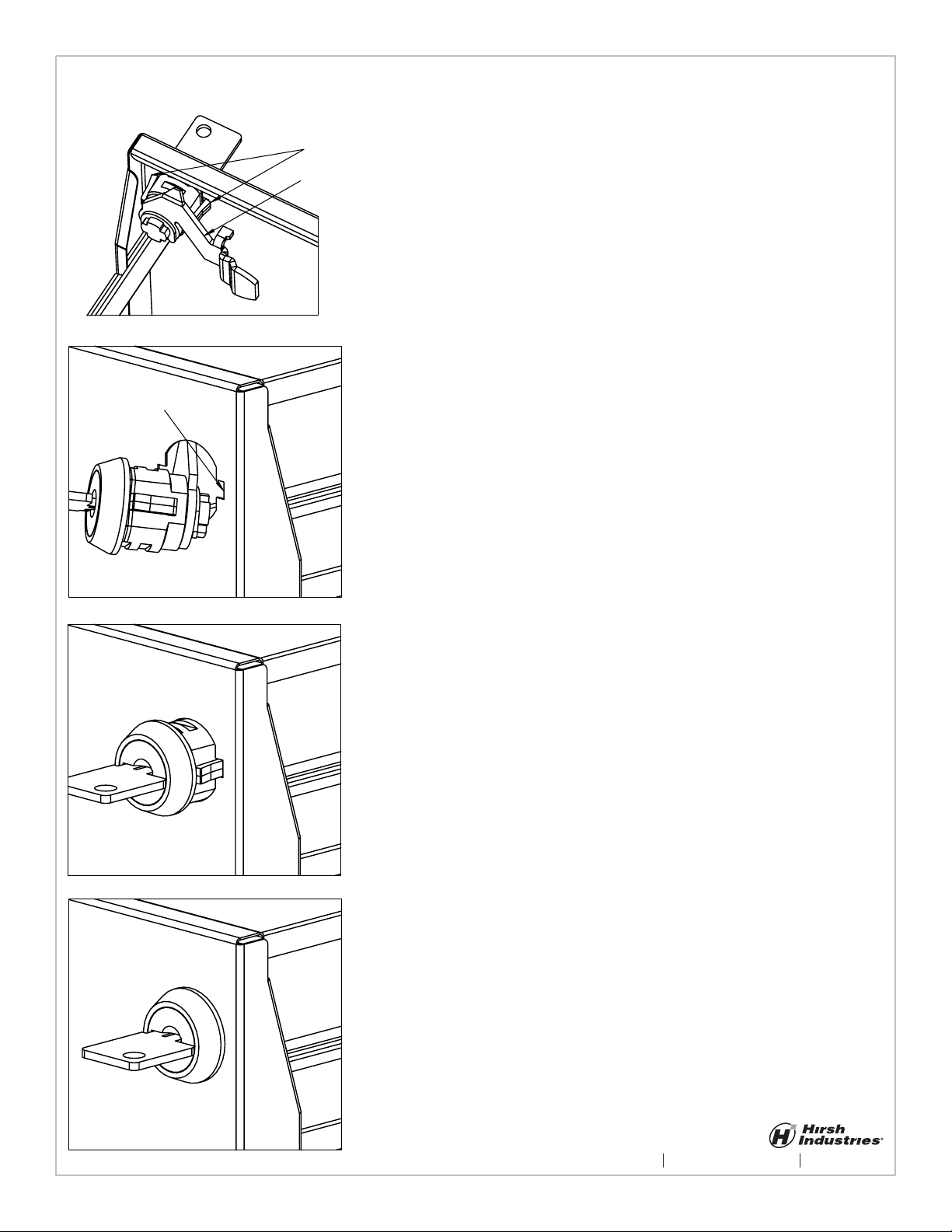
Figure 1
Wing Clip
Notches
Figure 2
Wing Clips
Lock Cam
Note: Do not place your ngers behind or slide
your ngers along the sheet metal edges.
To replace the lock in your le cabinet you
must rst remove the old lock.
To remove the old lock:
1. Open the drawer and locate the Wing Clips
which hold the lock in place. (Figure 1)
2. With a athead screwdriver push the Wing
Clips toward the lock body and push the lock
body forward until the Wing Clip on that side is
slightly protruding out of the drawer front.
3. Again using the athead screwdriver push
the Wing Clip on the other side toward the lock
body and push forward until the lock can be
removed from the drawer.
To install the new lock:
1. Make sure that the cam is in the unlocked
position by turning the key counterclockwise
as far as it will go.
Figure 3
2. Feed the lock cam through the hole in the
dawer front so the Lock Cam is pointing
toward the center of the drawer (Figure 2) and
align the Wing Clips with the notches in the
drawer front (Figure 3).
3. Push the lock into the drawer front until the
Wing Clips pass through the drawer front and
snap into place behind the drawer front (Figure
4).
Figure 4
3636 Westown Parkway, West Des Moines, Iowa www.hirshindustries.com 1-800-383-7414
SHEET 1 OF 1
Page 2
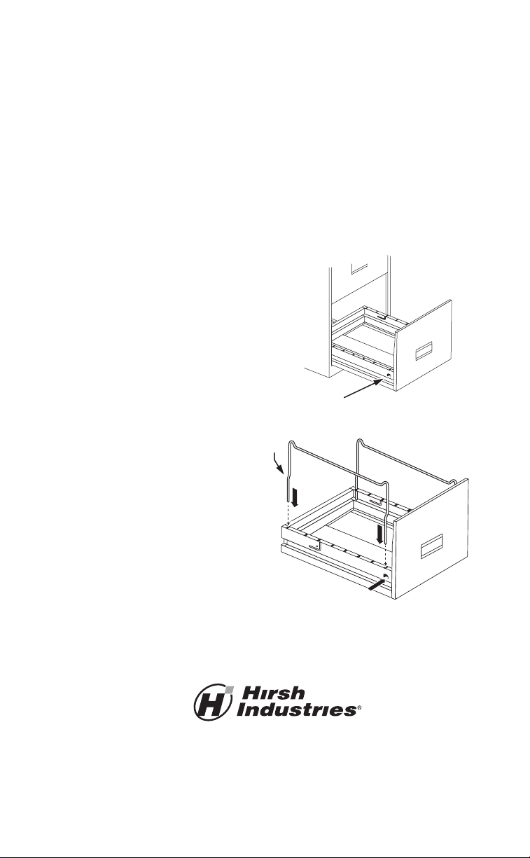
HANGING FOLDER SUPPORT INSTALLATION
This filing cabinet can be used with hanging file folders by simply
installing two folder supports per drawer as follows:
Step 1: Slide the drawer half way out of the
cabinet to allow access to the drawer sides.
Identify the two small square tabs on each
side of the drawer near the front. (See
Figure 1).
Step 2: From the outside of the drawer,
push the tabs inward until they are at
a 90 degree angle to the drawer side. (See
Figure 2).
Step 3: Install one folder support into each
drawer side through the top holes and then
through the square tab. (See Figure 2).
Note: After the installation of the support,
the bend in the support should remain
above the top of the drawer and should
point toward the center of the drawer.
Step 4: Place several hanging folders in the
drawer to ensure proper support positioning.
Step 5: Repeat steps 1-4 for each drawer.
Step 1
Figure 1
Square Tab
Bend
Step 3
Figure 2
Step 2
West Des Moines, Iowa www.hirshindustries.com 1-800-383-7414
No. 18900 09/2012
Page 3

Caster Kit Assembly Instructions
BEFORE YOU BEGIN
Open, identify, and count all parts prior to assembly.
(2) Front Caster
A.
(2) Rear Caster
B.
(8) Screw
C.
(2) Caster Bracket
D.
A.
B.
C.
D.
STEP 1 - Attach Front Casters:
Align screw holes in front caster mounting plate
with the screw holes in the bottom of cabinet.
Connect the Front Casters (A) with Screws (C)
using a phillips screwdriver. Fully tighten all screws.
C
A
mounting plate
2x
STEP 2 - Attach Rear Casters:
Position v-bends of Caster Bracket (D) up under cabinet rims.
Align screw holes in rear caster mounting plate with screw
holes in Caster Bracket (D) ensuring the mounting plate
covers the bottom corner of the cabinet. (Figure 4)
Connect the Rear Caster (B) and the Caster Bracket (D) with
Screws (C) using a phillips screwdriver. Fully tighten all
screws.
C
B
mounting plate
rim
D
2x
v-bend
FIGURE 3: Complete assembly. FIGURE 4: Close-up of rear caster assembly.
rear casters
Screw (C)
front casters
11/06/2013
www.hirshindustries.com 800.383.7414
 Loading...