

Page 1

Video over IP
Page 2

© 2000 Hirschmann Electronics GmbH & Co. KG
Manuals and software are protected by copyright. All rights reserved.
The copying, reproduction, translation, conversion into any electronic
medium or machine scannable form is not permitted, either in whole or
in part. An exception is formed by the preparation of a backup copy of
the software for your own use.
This manual has been created by Hirschmann Electronics GmbH & Co.
KG according to the best of our knowledge. Hirschmann reserves the
right to change the contents of this manual without prior notice. Hirschmann can give no guarantee in respect of the correctness or accuracy of
the details in this manual.
Hirschmann haftet in keinem Fall für irgendwelche Schäden, die in irgendeinem Zusammenhang mit der Nutzung der Netzkomponenten
oder ihrer Betriebssoftware entstehen. Im übrigen verweisen wir auf die
im Lizenzvertrag genannten Nutzungsbedingungen.
Hirschmann can accept no responsibility for damages, resulting from the
use of the network components or the associated operating software.
For the rest, we refer to the conditions of use specified in the license contract.
2
Release 1.0 09/00
VIP
Page 3

4
Release 1.0 09/00
VIP
Page 4

Contents
Preface 7
Purpose 7
Audience 7
Conventions 7
Special Message Formats 7
Other Conventions 8
Chapter 1 Introduction 9
Multimedia Gateway Concept 9
Typical Applications 10
Features and Benefits 10
Package Contents 12
Front Panel Connectors 12
Rear Panel Connectors 13
Chapter 2 Quick Installation Guide 15
Step 1: Connecting a Camera or Monitor 15
Step 2: Connecting to the LAN Port 16
Step 3: Connecting Power 17
Step 4: Selecting an IP Address for Your Network 18
1. Add MAC-address to the PC’s ARP routing table: 18
2. Assign the IP address using the ’p ing’ command: 18
Chapter 3 Hardware Installation 19
Connecting Video Sources or Displays 19
Connecting Audio Equipment 20
Connecting Data Terminals 21
Terminal Port 21
Transparent Data Port 21
Connecting External Sensors and Controlling Peripheral Devices 22
Connecting to a LAN 23
Chapter 4 Configuration 25
Configuration using a Terminal 25
Typical Session 25
Command Reference 26
Configuration Using a Web Browser 27
Web-Server Concept 27
VIP Home-Page 28
General Configuration Page 29
Video Configuration Page 33
Audio Configuration Page 35
Alarm Configuration Page 37
Interface Config uration Page 41
5
Page 5

Chapter 5 Typical Applications 43
Displaying Remote Video on a Web Browser 43
Connecting a
Multimedia over LAN Concept using
Intranet vs. Internet Operation 47
VIP transmitter to a VIP receiver 44
Chapter 6 Advanced Features 49
Automatic Connection Feature 49
Video Motion Detection Feature 49
Alarm Notification by Email 50
Firmware Upload 50
Dynamic Allocation of an IP Address using the DHCP Protocol 52
Technical Specification 53
Network Protocol and Standards Compatibility 53
Interfaces 53
Power Adapter 53
Physical Specification 54
Environmental Specification 54
Electromagnetic Emissions & Safety 54
Troubleshooting 55
General Service Remarks 55
Basic Functioning 55
Power LED 55
LAN Link LED 56
Transmit LED 56
Terminal program 56
Troubleshooting a TCP/IP Network Using a Ping Utility 56
Troubleshooting Connection Problems 57
Troubleshooting the Video Connection 57
Testing the Audio Connection 58
Restoring the Default Configuration 59
Glossary 61
Index 63
VIP -SW1 45
6
Video over IP Handbuch
Page 6

Purpose
Preface
Congratulations on your purchase of the Hirschmann VIP multimedia LAN
adapter.
The
VIP multimedia LAN adapters provide connectivity for video, audio
and data sources over Ethernet networks using the TCP/IP protocol. The
units are available as encoder units
connection of video sources as cameras for example, or as decoder units
VIP - VRx, providing a video output for direct connection of a monitor.
VIP allows for transport of video, accompanying audio (optional) and
data over Intranets or the Internet.
This manual describes the features of the VIP unit and provides installation
and configuration instructions. When discussing features, functions, or
specifications that apply to both encoder and decoder models, the manual refers to the
VIP unit.
VIP - VTx, featuring a video input for
Audience
Conventions
To configure and install the VIP units, you should have the following background and experience:
• Working knowledge of basic network management con ce pts and
terminology.
• Working knowledge of tools and procedures for installing and operating sensitive electronic equipment.
Special Message Formats
This manual uses the following symbols and notation in order to highlight
special messages:
Wherever this symbol appears certain information is required for correct
configuration and operation. Eventually you need to talk to users, manufacturers of connected equipment or a system administrator in order to
gather the required information.
This symbol marks hints and tips which will make the usage of your
simple and comfortable as possible.
Preface 7
VIP as
Page 7

All instructions which are acco m pa n ie d by th e sho wn symbol should be
carefully followed in order to avoid potential damage to your
nected equipment and ensure your personal safety.
VIP or con-
Other Conventions
This manual uses the following typographical conventions:
italics Command and directory names.
courier font Screen text, us er-typed command-line entries.
“courier font” User typed string, enter without double quotes.
Initial Caps Menu titles and window and button names.
[Enter] Named keys in text are shown enclosed in square
brackets. The notation [Enter] is used for the Enter key
and the Return key.
[Ctrl]+C Two or more keys that must be pressed simultaneously
are shown in text linked with a plus (+) sign.
ALL CAPS DOS file and directory names.
<courier font> Screen output, dependent on keyboard entry.
8
Video over IP Manual
Page 8
CHAPTER 1 Introduction
For the first time, VIP realizes live video transmission via existing computer
networks. Efficient compression, according to the ITU-T standard H.261,
enables video communication over virtually any TCP/IP connection: local
area networks as well as the Internet (wide area network).
Simply configure an IP address using a standard terminal program or any
Internet Browser and connect
required.
VIP to the Ethernet. That’s all the installation
This chapter will familiarize you with the underlying concept of the
timedia gateway, will provide an overview of the features and will give
examples of typical applications. After an introduction to the front and
back panel connectors, you are in a good positi on to follow the ins tallation
and configuration details given in the succeeding chapters.
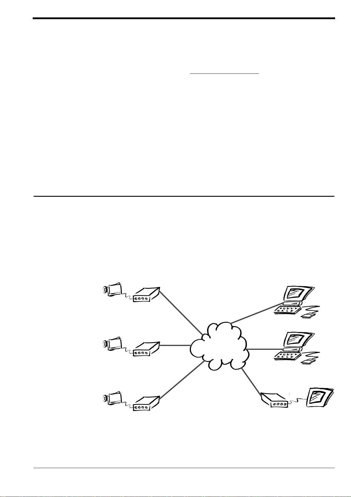
Multimedia Gateway Concept
Continuous media such as video and audio are meant to be transported
over dedicated lines, for example coaxial cables. With computer networks
becoming ubiquitous and unde r the umbrella of the Internet, there is a
trend to integrate all sorts of data types into computer networks. This trend
is driven by the request for a single network, yielding significant savings in
reduced costs and simpler installation and management of a single network.
VIP - VTx
Transmitter
VIP mul-
Web Browser
LAN/WAN
VIP - VTx
Transmitter
TCP/IP
Intranet/Internet
VIP - VTx
Transmitter
Figure 1.
Introduction 9
VIP Multimedia Gateway Concept
VIP -SW1 VIP -
Software-Decoder
VIP - VRx
Receiver
or
Monitor
Page 9

The VIP multimedia gateway was designed, to integrate multimedia data
streams into computer networks based on Ethernet and the TCP/IP protocol suite.
of-use, enabling you to transmit full color live video with accompanying
full-duplex audio and data over standard Ethernet-type networks.
VIP combines state-of-the art compression technology with ease-
VIP comes in two flavors, as a VIP - VTx sender or as a VIP - VRx receiver.
The sender will connect any PAL or NTSC video source to the computer network. Conversely, the receiver will display the video on any standard PAL or
NTSC monitor. Alternatively, video is received via the
software decoder (see separate datasheet) on any PC in the network.
Remote control of peripheral components like pan/tilt/zoom cameras is
facilitated by the bidirectional serial interface. Transmission of full duplex
audio is an option.
From the user’s perspective, video sources such as cameras, are identified
by IP addresses, just like any other equipment connected to a computer
network. As shown in Figure 1, there are 3 choices for display of remote
video streams:
• Web Br owser using any PC on the network
•
VIP -SW1 or VIP -SW1 software application
•
VIP - VRx hardware receiver and attached moni tor
VIP -SW1 or VIP -SW1
Typical Applications
VIP provides a s et of advanced feat ur es for r emot e video surv eill ance and
security: the integrated motion video sensor will setup a connection autonomously when motion in the scene is detected. Pre-alarm history is stored
in a video ring buffer for alarm verification:
• Video surveillance of rooms and buildings
• Remote maintenance of machinery
• Facility managem ent and facility security
Features and Benefits
VIP is a flexible, high- pe rformance, eas y -to-use device that provides a
cost-effective solution for trans mission of live video and audio across Ethernet networks. With a minimum of setup, you can install and use
minutes to realize a great variety of applications. The versatility and performance of
• Live video, audio, and data transmission over computer networks
• Compact autonomous system, no PC required at the sender side
• Easy to use: integrated HTTP server for Browser-based configuration
• High quality, full- motion, full-color live-video, ITU- T H.261 standard
• High video resolution up to 352 x 288 pixels at 25 frames/s (max.)
• Sender and receiv er units available
VIP within
VIP is highlighted by the following list of features:
(Ethernet, TCP/IP)
and display of JPEG-encoded video
compatible
10
Video over IP Manual
Page 10
• Reception and playback via VIP -SW1 or VIP -SW1 software decoder
Eth
t
• Transparent full-duplex data channel (RS232), e.g. for pan/tilt/zoom
camera control
• Full-duplex audio transmission (optional)
• Control input for external sensors, e.g. switch or contact
• Relay output for switching of external devi ces , e.g. d o or entry
• Password protection against unauthorized access
• Integrated video motion sensor for security applications
• Video ring buffer for pre-al arm history
• Autonomous connection setup
• Automatic sending of alarm email messages with attached picture
• Remote control of all internal functions via UDP/IP
• Flash memory for firmware upgrade
• Optional X.21 lea s ed line in terfac e
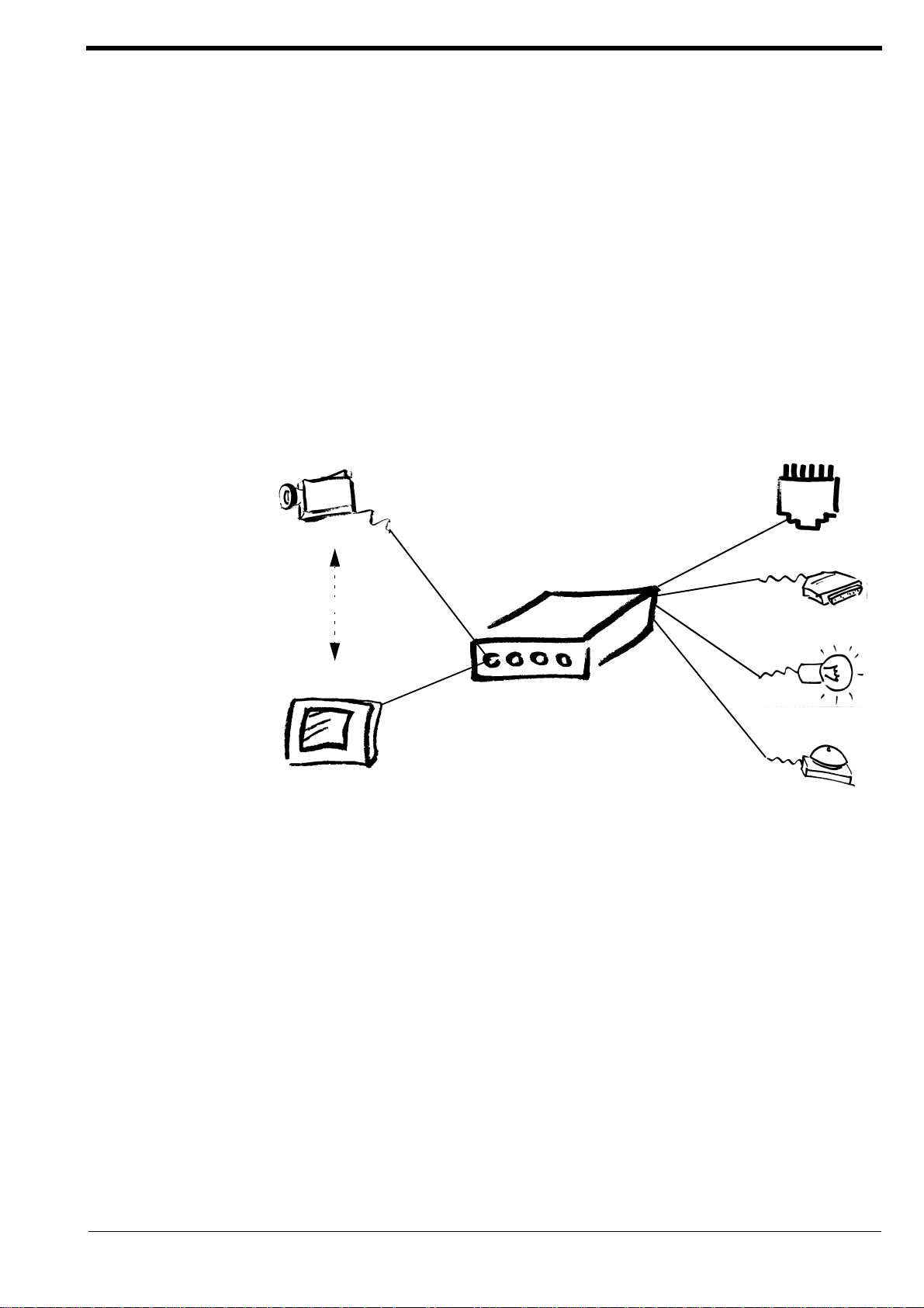
Camera
erne
UTP
serial interface
VIP
alternatively
relay output
Monitor
control input
Figure 2.
Summarizing,
mission of live video and audio. The use of existing networks yields significant savings in terms of installation (no separate cabling required), toll-free
operation (Intranets), and management (single uniform network).
VIP features and interfaces
VIP enables you to use any existing data network for trans-
Introduction 11
Page 11
Package Contents
The product package should contain the following items:
VIP - VTx or VIP - VRx unit
•
• AC plug power adapter, 5V DC output
• This manual
Call your distributor or the dealer if there are any wrong, missing, or
damaged parts. Keep the carton, including the original packaging material, to repack the equipment if there is a nee d to return it for repair.
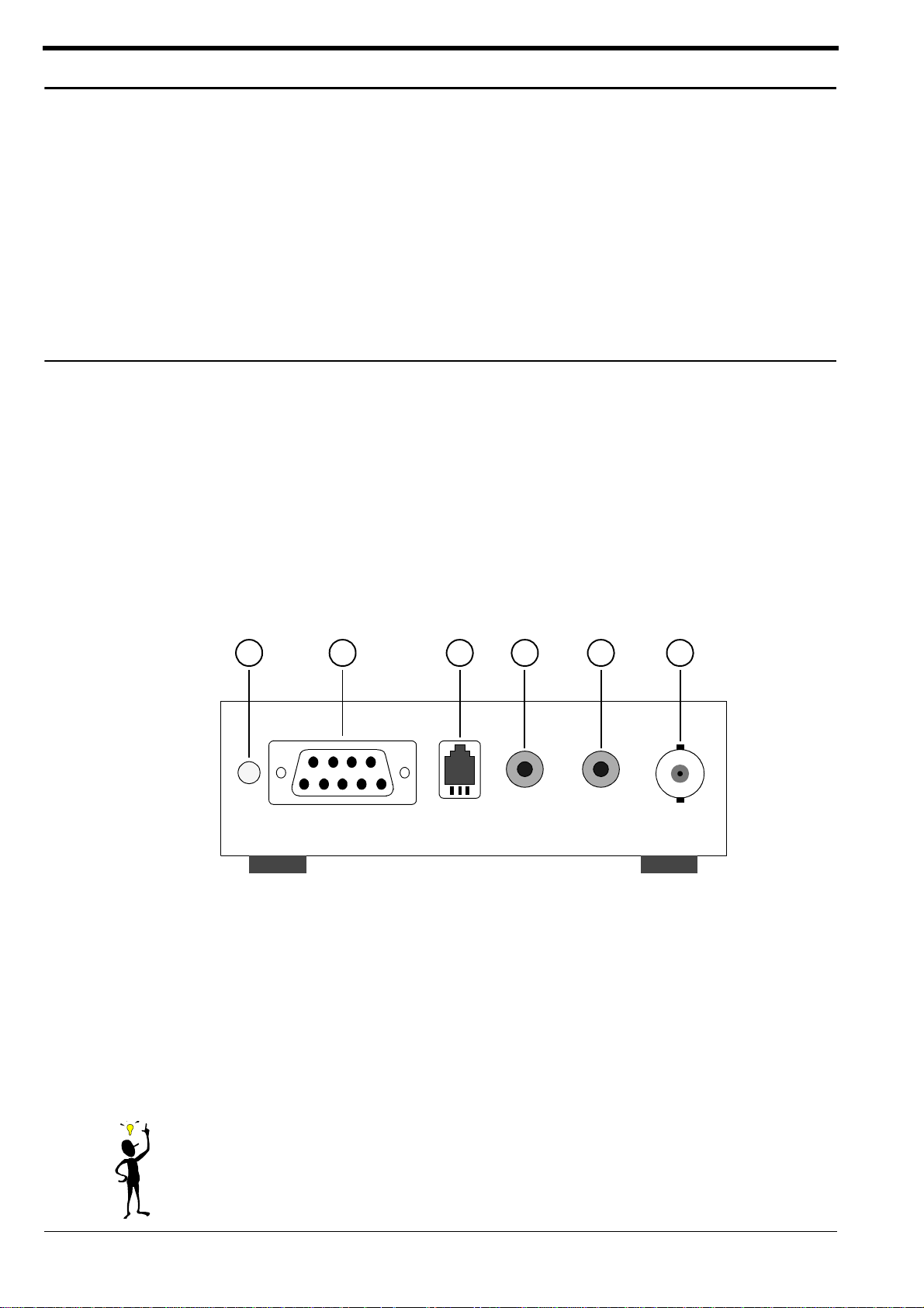
Front Panel Connectors
One of the VIP benefits is compact design, enabling you to install the unit
in the most confined environments, e.g. installation ducts or camera housing. Compact design was made possible in part by placing connectors at
the front and the rear panel. The front panel connectors are dedicated to
the media interfaces, i.e. video, audio and data, and are depi ct ed in Figure 3.
1 2 3 4 5 6
Key:
1 = Green Power LED, blinking when connected to
another
2 = RS-232 transparent data port for connectin g to peripheral equipment
3 = Handset port (only with audio option)
4 = Audio line output (only with audio option)
5 = Audio line input (only with audio option)
6 = Video input (for
Figure 3.
VIP unit
VIP - VTx) or video output (for VIP - VRx)
VIP Front Panel Connectors
VIP -SW1 or
12
Note that the audio connectors, (3), (4) and (5), are only functional for
units equipped with the optional audio interface. The model name is
appended by the letter ’A’ for audio in this case:
sending unit with in stalled audio option , w h ere a s
VIP - AVTx denotes a
VIP - AVRx denotes the
Video over IP Manual
Page 12
corresponding receiver unit. Otherwise there is no difference in features,
therefore all information given for the basic units
does also apply to the models with integrated audio functionality.
The green power LED will be lit as soon as power is supplied to the unit and
the unit is ready fo r service. During an active connection to a
decoder, or
cate the connection status.
The serial interface for transparent data transmission does only provide
serial send (pin 3) and receive (pin 2) signals and ground (pin 5). No hard-
ware flow control signals are provided.
The handset interface facilitates direct connection of a telephone hand-
set. Note that either the handset or the line interface is active at any given
time. Selection of the interface is described in chapter 4. For a detailed
description of the audio interface refer to chapter 3.
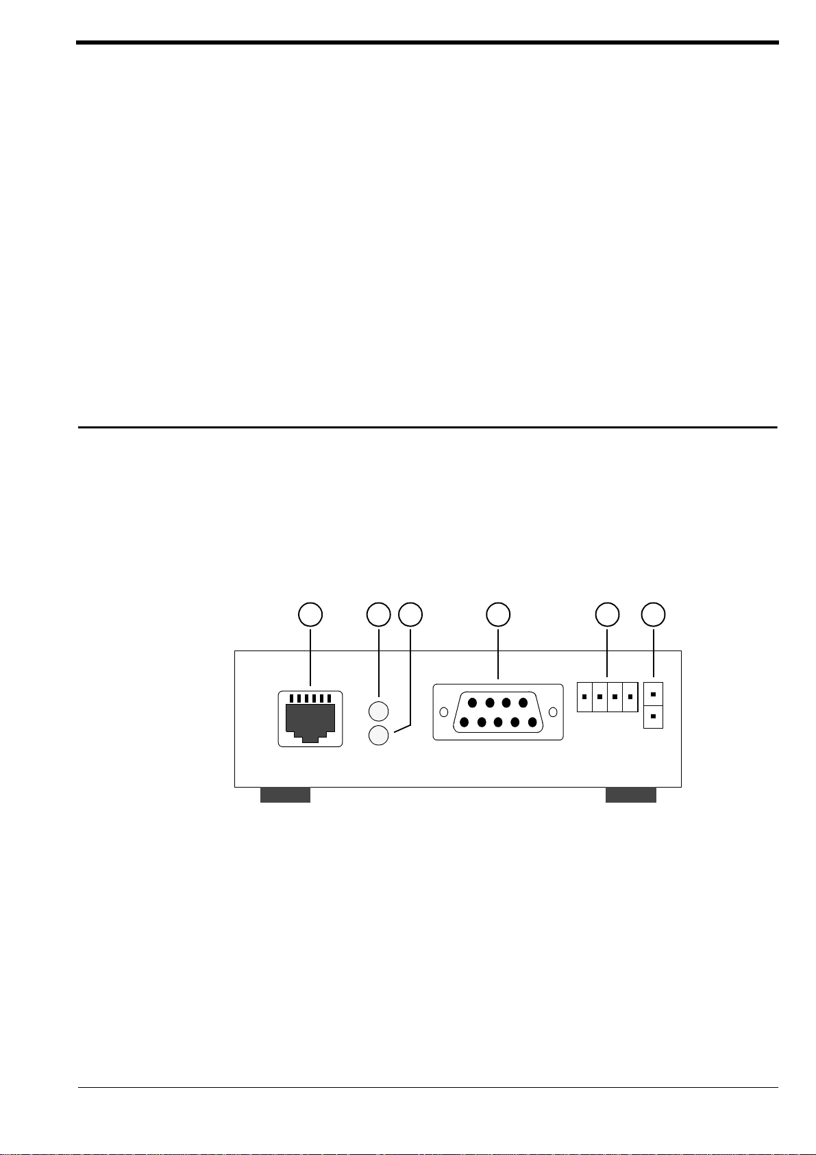
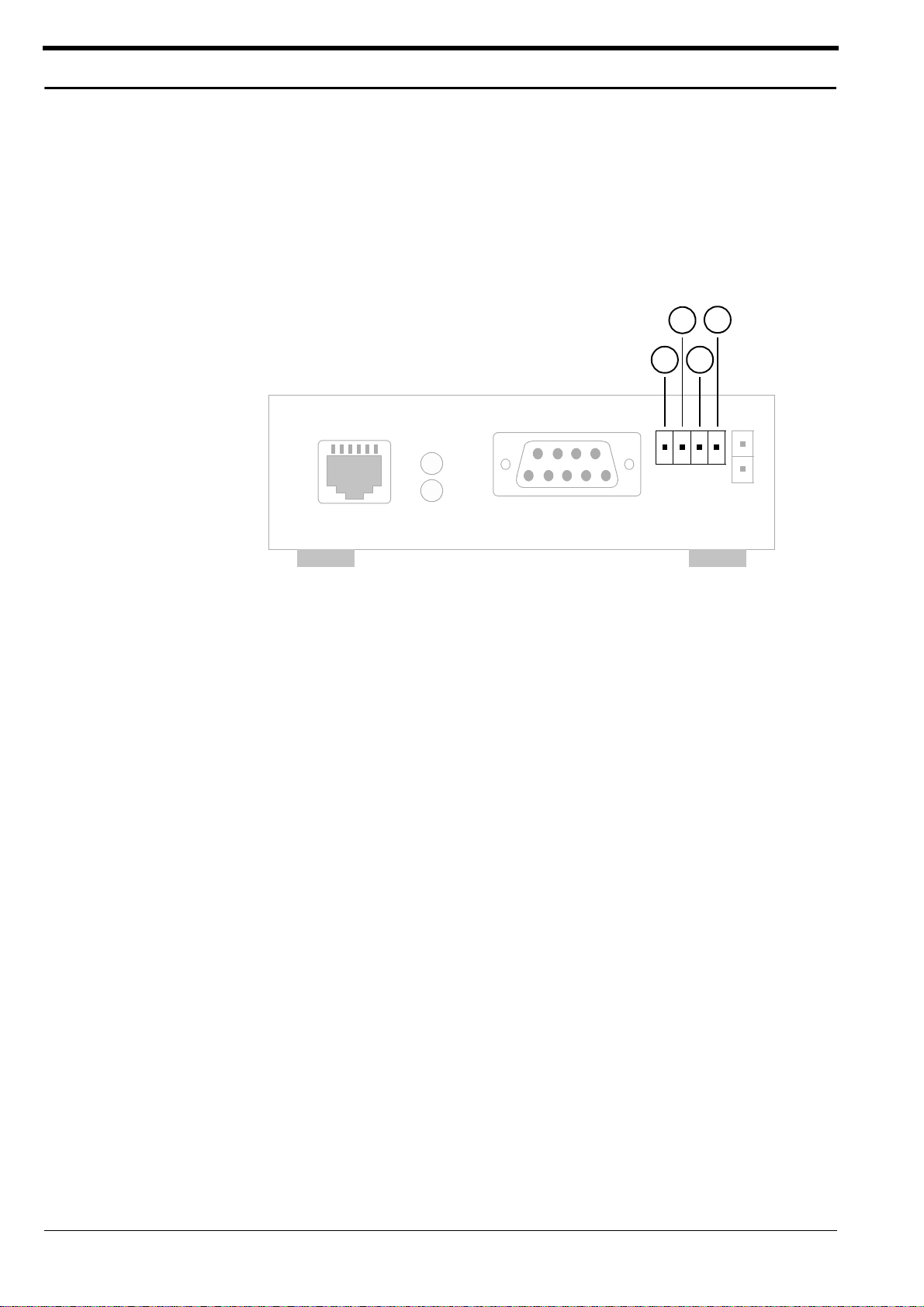
Rear Panel Connectors
On the rear panel of the unit you will find the network interface, a terminal
port for configuration and managem ent, a switching I/O-port and the
power connector, see Figure 4.
VIP - VTx and VIP - VRx
VIP - VRx
VIP -SW1, VIP -SW1 software decoder, the LED will blink to indi-
21 3 4 5 6
Key:
1 = UTP port for connecting
2 = Yellow TX LED for monitoring packet sending over the UTP port
3 = Green LINK LED for link test of UTP connection
4 = RS-232 the serial port of a PC
5 = Signalling input and relay output
6 = Power connector for connecting the AC plug power adapter
Figure 4.
VIP Rear Panel Connectors
VIP to the LAN with UTP cable
The green LINK LED will provide LAN status information: If the LED is on, the
LAN port is properly connected and synchronized to a LAN. The yellow TX
Introduction 13
Page 13

(Transmit) LED will blink for each packet being transmitted. Note that
packet reception is not signalled.
The RS-232 interface allows for connection to the serial port of a PC for simple configuration and/or operation management functions. The interface
features the full sui t e o f RS-2 3 2 fl o w cont rol signals.
The switching I/ O-p o rt al lo w s for di rect connection of ex ternal signalling
devices, for example knobs or contacts. Also, the relay output facilitates
switching of periphera l device s, for e xamp le l i ghts or el ectr ic door ope ner s.
Note: Use only the supplied AC plug power adapter. If the adapter, the
cable or the connector show any sign of damage, do not use the power
adapter and send it in for repair or replaceme n t. Ne ver atte m pt to interface any other power adapter other than the supplied one.
Refer to chapter 3 for a comprehensive discussion of interfacing peripheral
devices to the
VIP unit.
14
Video over IP Manual
Page 14
CHAPTER 2 Quick Installation Guide
For the fastest route to get your product up and running, just follow the next
4 steps below.
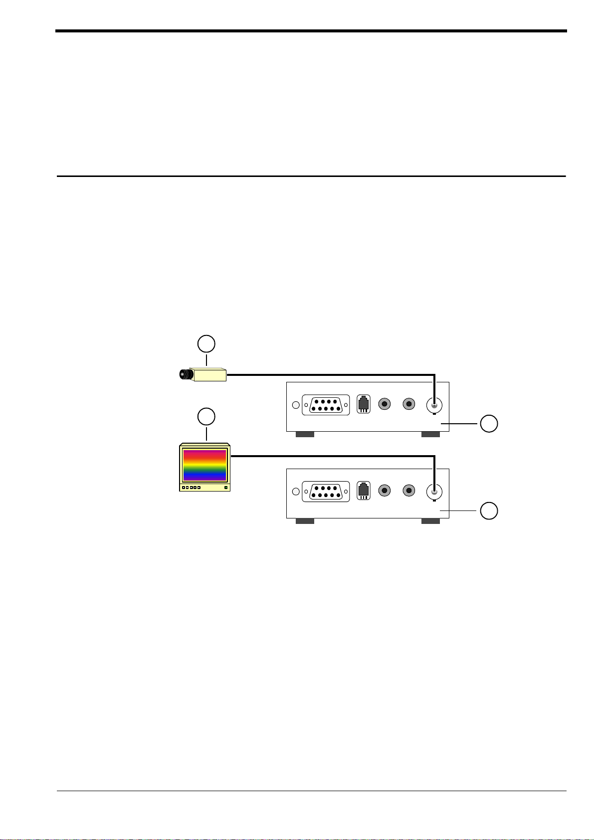
Step 1: Connecting a Camera or Monitor
To connect a camera to the VIP - VTx transmitter use a standard coaxial
cable and plug it into the BNC connector at the front side of the unit. Any
video source with a composite PAL or NTSC output may be used.
In order to connect a monitor to the
coaxial cable and plug it into the BNC connector at the front side of the
unit. Any PAL or NTSC video monitor with a composite PAL or NTSC input
can be connected.
VIP - VRx receiver use a standard
1
2
3
4
Key:
1 = Camera or other video source with composite PAL or NTSC output
2 = Video Monitor with composite PAL or NTSC input
3 =
VIP - VTx transmitter
4 =
VIP - VRx receiver
Figure 5. Connecting a Camera or Monitor
For more information regarding video sources and monitors refer to the
next chapter.
Quick Installation Guide 15
Page 15
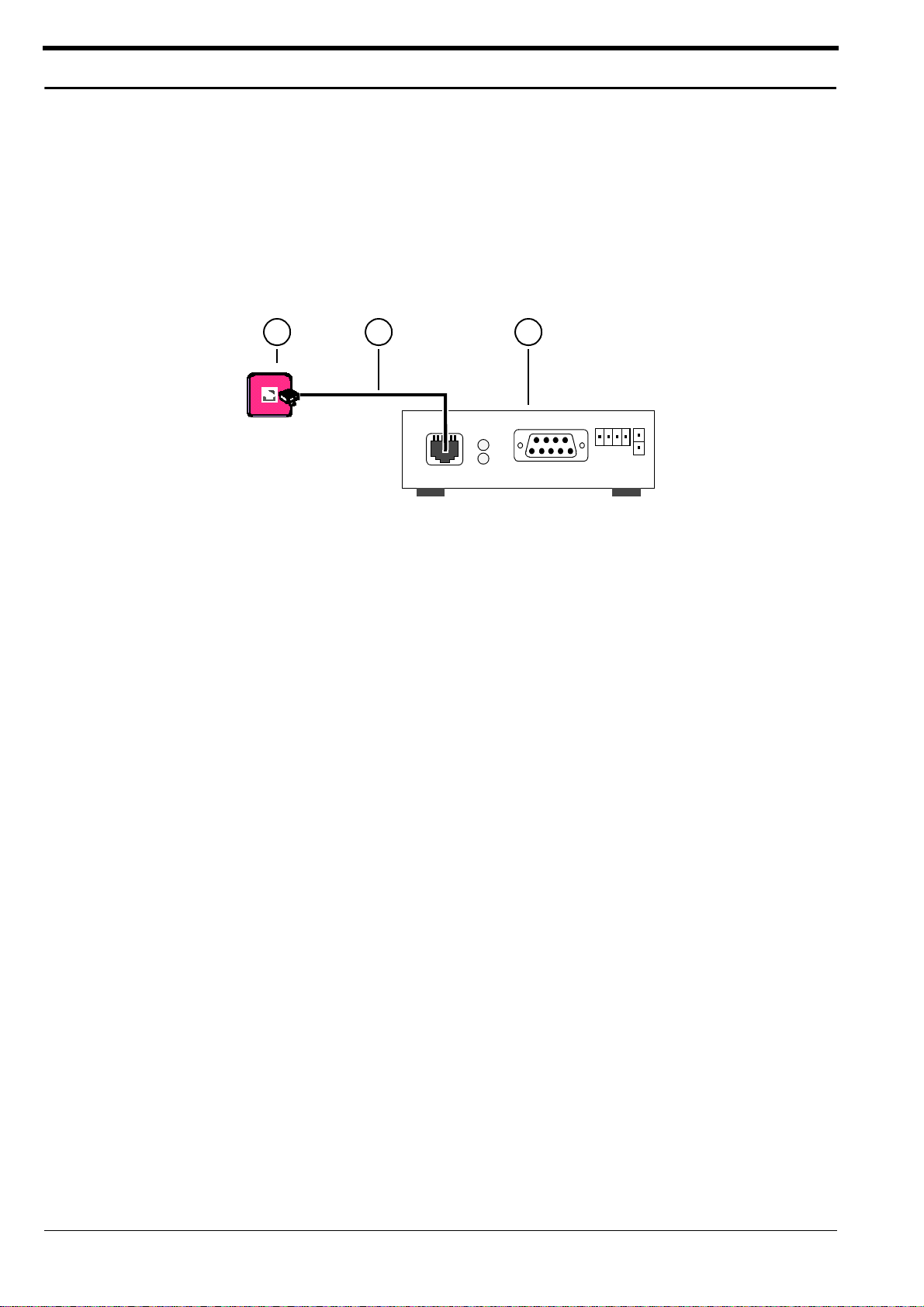
Step 2: Connecting to the LAN Port
To connect the VIP to the Ethernet network use a standard UTP Cat5 cable
with RJ45 connectors. Plug th is ca ble into the RJ45 receptacle la be lle d
„Ethernet/UTP“ at the rear side of the unit. The connection to a 10BASE-T
network can be made directly or via a hub or switch.
A correct connection is indicated by the green „LINK LED“ next to the RJ45
connector.
21 3
Key:
1 = UTP (10BASE-T) LAN connection to hubs, network, PCs
2 = UTP Cat5-cable
3 =
VIP - VTx transmitter or VIP - VRx rec eiv e r
Figure 6. Connecting to the LAN Port
16
Video over IP Manual
Page 16
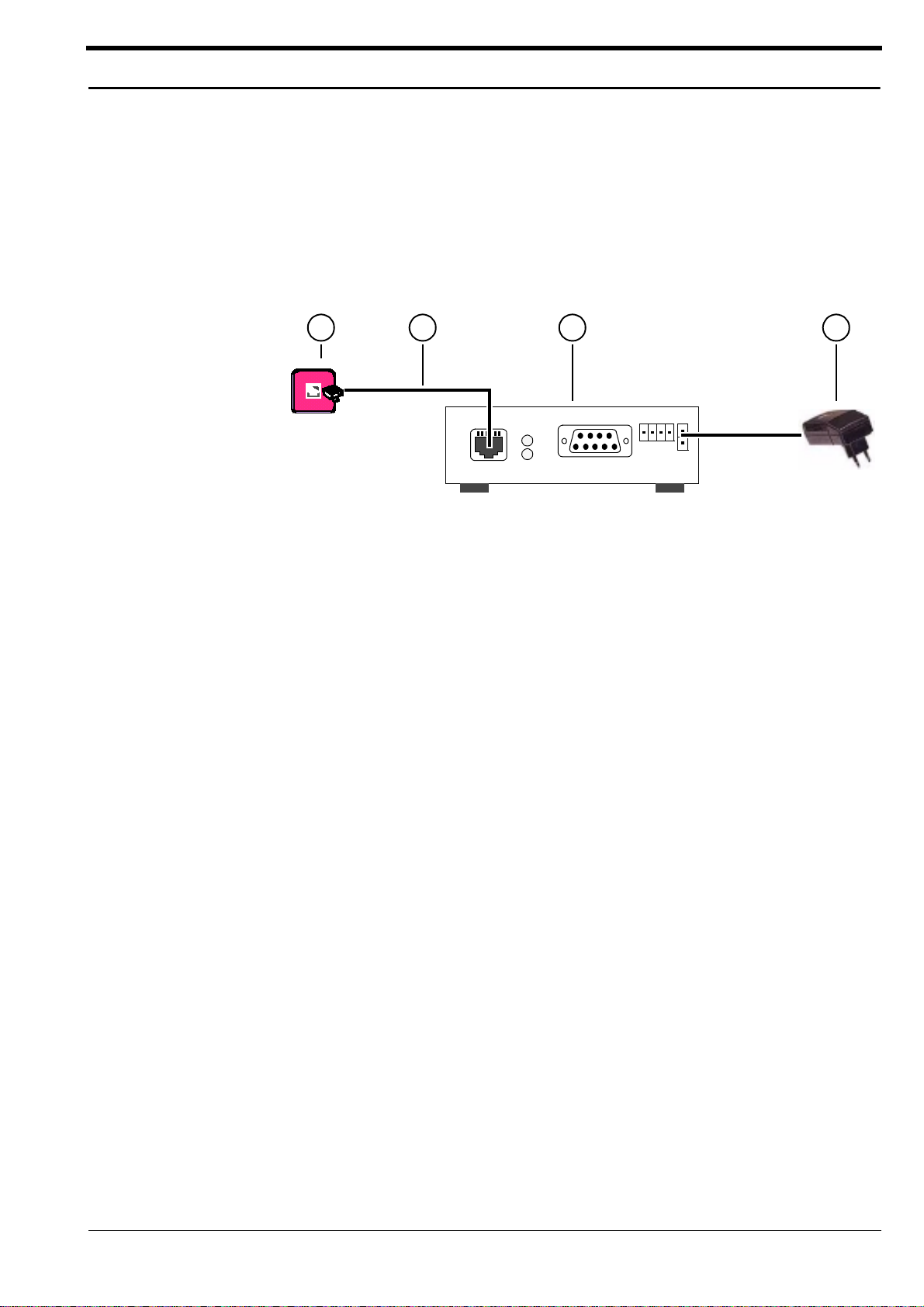
Step 3: Connecting Power
After connecting the video source or the monitor and the LAN cable to the
unit, the power adapter has to be attached to the
side into the wall outlet and the secondary side with the small clip into the
unit.
VIP. Plug the primary
When the power adapter is connected correctly to the
power LED at the front side is lit constantly.
VIP, the green
21 3 4
Key:
1 = UTP (10BASE-T) LAN connection to hubs, network, PCs
2 = UTP Cat5-cable
3 =
VIP - VTx transmitter or VIP - VRx receiver
4 = AC plug power adapter
Figure 7. Connecting Power
Quick Installation Guide 17
Page 17

Step 4: Selecting an IP Address for Your Network
VIP comes with the default IP address of 192.168.0.1. Before operating
the system inside your own network, a valid IP address needs to be set.
offers 3 convenient ways for configuring IP addresses:
1. Using command line tools, e.g. in a DOS box.
2. Using a terminal program attached at the RS -232 control terminal port.
3. Using a Web Browser.
In the following, IP ad d res s co n f ig ur ati o n us in g comm and line tools is
described in detail. For a description of IP address configuration using a terminal program or a Web Browser refer to chapter 4.
The command line procedure for configuration of an IP address requires
the
VIP to be located in the same subnet as the configuring PC. Two steps
are required:
1. Add MAC-address to the PC’s ARP routing table:
You first have to make the VIP known to the ARP routing table of the PC,
which you are using for the configuration. The ARP routing table links the
hardware or so-ca lled MAC address to the IP address to be configured.
The MAC address of the unit can be found on the bottom label of the unit.
At the command line, in a DOS box, type the following:
VIP
C:\>arp -s "IP address" "MAC address"
For example, the command line
C:\>arp -s 192.168.0.5 00-60-54-04-F5-94
will link the IP address 192.168.0.5, which is the one to be configured, to
the unit’s MAC address 00-60-54-04-F5-94. The command will add an
entry into your PC's ARP table. Check the new entry by typing:
C:\>arp -a
The entry should appear in the displayed list. It is possible, however , that the
PC will not add a new entry into an otherwise empty table. In this case, just
’ping’ any other PC or network device and try again.
2. Assign the IP address using the ’ping’ command:
Step 1 above was required in order to reach the VIP unit to be configured.
The actual configuration of the unit is carried out using the ’ping’ command. By typing
C:\>ping "IP address"
the PC system will send a message (ICMP) to the
the attached IP address and will con figu re itsel f acco rd in gl y. At lea s t one
positive reply should appear on the PC screen. If there are no replies, the
VIP unit is not connected properly or is not located in the same subnet as
your PC. In this case you either have to use another way to configure the IP
address or reconfigure the network arrangement.
VIP unit, which will fin d
18
Video over IP Manual
Page 18

CHAPTER 3 Hardware Installation
The following chapter describes in detail how to connect external devices
to your
Connecting Video Sources or Displays
For connecting a camera to the VIP - VTx transmitter, use a standard
coaxial cable and plug it into the BNC connector at the front panel of the
VIP - VTx. Any camera or other video source, e.g. a VCR with a composite
PAL or NTSC output can be connected. The input accepts color or B&W
sources and automatically detects the standard (PAL or NTSC). When using
VCRs as input source the video quality can be improved by setting the
Input Source in the Video Configuration Page (see chapter 4) to VCR. The
video input is equipped with an internal termination with 75 Ohms.
VIP system.
To connect a monitor to a
and plug it into the BNC connector at the front panel of the
PAL or NTSC video monitor with a composite PAL or NTSC input can be
connected. Moreover a VCR can be connected to store the received
video on a VCR tape.
The default output format is composite PAL. To switch the video output to
composite NTSC set t h e Output Standard in the Video Configuration Page
(see chapter 4) to NTSC.
VIP - VRx receiver use a standard coaxial cable
VIP - VRx. Any
Hardware Ins tallation 19
Page 19
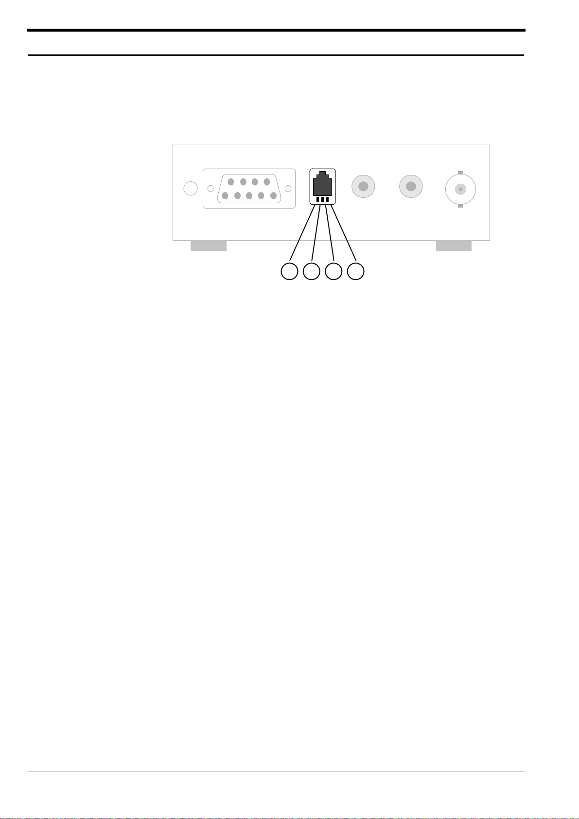
Connecting Audio Equipment
If the VIP is equipped with the audio option, basically two audio channels
are available, called handset and audi o in/out. Only one of these two
audio interfaces can be active at one time.
Key:
1 = Handset Microphone, positive terminal
2 = Handset Speaker, positive terminal
3 = Handset Speaker, negative terminal
4 = Handset Microphone, ground terminal
21 3 4
Figure 8. Pin Assignment of the Handset RJ-11 receptable
A handset can be connected to the RJ11 receptacle labelled Handset at
the front panel of the
radio button labelled Handset in the Audio Configuration Page.
The input and output level ranging from 0...100% can also be set in this configuration menu. Moreover, the coding mode at the sending side can be
set using the menu item Coding mode between two different modes or
switched off.
The audio decoder will a utomatically follow the selected audio coding of
the transmitter. In cases where the receiver is not capable of decoding the
selected mode, e.g . sof tw a re de co d er, an automatic so-called fall-back
to the next available audio mode occurs.
The second audio channel is available at the two cinch receptacles
labelled Audio In and Audio Out at the front panel of the
this channel the radio button Line In/Out in the Audio Co n f ig ur ati on Page
has to be selected. The level and coding mode settings apply to this channel in the same manner as describ ed above for the first channel.
VIP. In order to select this audio interface check the
VIP. To choose
20
Video over IP Manual
Page 20

Connecting Data Terminals
VIP features two serial interfaces, at the front and the back pane l respec-
tively. They serve different purposes and cannot be used interchangeably,
as is explained in the fol lo win g :
Terminal Port
For local control and configuration of the VIP unit a data terminal (e.g. a
PC running a standard terminal program) can be connected to the serial
interface labelled Control Terminal on the rear panel. The 9-pin DSUB con-
nector feature s a stand ard RS -232 int erface that can be connecte d to any
PC’s COM-port.
A standard terminal program may be used to communicate with the
The default parameters are set to 19200 baud with 8 bits of data, one stop
bit and no parity bit (8N1).
An online help function can be evoked by typing ’?’ in the terminal win-
dow. For more information on the command set refer to chapter 4.
VIP.
Tra n sparent Data Port
The second serial interface on the front panel of the VIP offers a transpa-
rent serial data channel between the receiver (e.g. COM-port of a PC)
and the
channel are remote control of peripheral equipment, e.g. pan/tilt/zoom
facilities of selected cameras. In addition this channel can be used for
remote control of any external device with a serial interface. The serial
data is transferred in parallel to the video and audio data.
Note that transmission of transparent data is enabled only after a video
connection has been established. Also note that the RS-232 interface for
the transparent data port does not support hardware flow control.
VIP - VTx transmitter. Typical applications for the transparent data
Hardware Ins tallation 21
Page 21
Connecting External Sensors and Controlling Peripheral Devices
VIP is equipped with an alarm input to be used for external signalling
devices, like door contacts or motion detectors. Switches or contacts can
be connected directly without a separate power supply. The signalling
input is located on the two left pins of the detachable screw terminal (see
Figure 9).
2
1 3
4
Key:
1 = Alarm Input, positive terminal
2 = Alarm Input, ground terminal
3 = Relay Output, Y
4 = Relay Output, Z
Figure 9. Pin Assignment of the I/ O Con n ector
The input is activated by connecting pin1 to pin 2. Triggering of an alarm
may be configured to occur upon closing (=active high) or openi ng
(=active low) the contact between pin 1 and pin 2. Also, alarm action, e.g.
connecting to an alarm IP address or sending an alarm email, can be configured. Refer to chapter 4 for a discussion of the p o ssibilities.
The relay output may be operated interactively, during an active connection, or automatically to coincide with certain events. Again, configuration
items include comprehensive settings of the switching behavior of the relay
(chapter 4).
Typical applications of the relay output are the activation of electric door
openers or the switching of lights and othe r electrical devices. Do not
exceed the maximum rating of 24V/0.5A.
22
Video over IP Manual
Page 22

Connecting to a LAN
For connection of the VIP to a 10BASE-T network a standard UTP/Cat5
cable with RJ45 connector has to be plugged into the receptacle labelled
Ethernet/UTP at the rear side of the unit. The connection to the Ethernet
network can be made directly or via a hub. The green L INK LED at the rear
panel of the
sically correc t and synchronized with the LAN. Check the cable or see
appendix B for troubles hooting.
VIP unit is on as soon as the connection to the network is phy-
The yellow TX-LED above the LINK LED is lit whenever
packet over the network.
VIP is transmitting a
Hardware Ins tallation 23
Page 23

24
Video over IP Manual
Page 24

CHAPTER 4 Configuration
Two possibilities exist for configuration:
• Most basic control and configuration is obtained by connecting a terminal to the RS-232 terminal port.
• Most comfortable configuration and display of video is fac ilitated by
the built-in HTTP server, which connects to any standard Web Browser.
Configuration using a Terminal
Using a terminal program connected to the RS-232 terminal port at the rear
panel of the
bilities. Ensure that the COM port of the used PC is set up properly (default
parameters are 19200 ba ud, 8N1) and that the local terminal echo is disabled.
All commands consists of single characters, which are typed inside the terminal window. The following section shows a typical terminal session:
VIP unit will allow for limited configuration and control capa-
Typical Session
Typing a question mark ’?’ will prompt the VIP unit to output the help
screen on the terminal window:
*******************************************
Help menu
'?' this site
'i' set the IP address
's' set the subnet mask
'g' set the gateway IP address
'a' set the alarm IP
'c' connect to alarm IP
'd' disconnect
'm' display MAC address
'v' display version information
't' toggle DCHP On/Off
disable 'local echo' for a better display !
*******************************************
If you are using the terminal to set up the unit's IP address, just type 'i' and
you are prompted to enter a new IP address:
i
->Enter new IP address (old:192.168.0.1): 192.168.0.5
[Enter]
->IP address set to 192.168.0.5
Note: There are no backspaces allowed during a terminal session; if you
have mistyped a character, just terminate your entry by pressing [Enter]
and try again. If you see duplicate characters on entry, the 'loca l ech o'
feature of your PC's terminal program is not disabled.
If you want to establish a live video connection to a remote
VIP or VIP -
SW1, you have to specify the remote IP address by typing 'a' and entering
the remote IP address in the same manner as the unit IP above.
Configuration 25
Page 25

In order to establish a connection type 'c', to disconnect 'd'. Be sure not to
connect two units of the same type, e.g. receiver to receiver. Likewise, a
connection between a
VIP - VRx receiver and a VIP -SW1 software
decoder does not make sense.
Command Reference
The following table gives an overview about all available commands:
Cmd Description
? Displays the help screen
i Set up a new IP address
->Enter new IP address (old:192.168.0.1): “new IP address”
[Enter]
->IP address set to <new IP address>
s Set up a new subnetmask
->Enter new subnet mask (old:255.255.255.0): “new subnet
mask” [Enter]
->subnet mask set to <new subnet mask>
g Set up a new gateway IP address
->Enter new gateway IP address (old:192.168.0.10): “new
gateway IP address” [Enter]
->gateway IP address set to <new gateway IP address>
a Set up a new alarm IP to connect to
->Enter new alarm IP address (old:192.168.0.3): “alarm IP address” [Enter]
->Alarm IP address set to <new alarm IP address>
c Connects a live video to the specified alarm IP
->connecting...
connected
d Disconnects any pending video connection
->disconnecting...
disconnected
m Display the unit's MAC address
->MAC address: <unit's MAC address>
VIP tries to call the alarm IP host
VIP has established the connection
VIP disconnects
VIP has disconnected
26
v Display version information
->HW version: <version number> SW version: <version number>
t Activates/deactivates the DHCP protocol for automatic allocation of an
IP address after power up.
Table 1. Terminal Command Reference
Video over IP Manual
Page 26

Configuration Using a Web Browser
In addition to the aforementioned configuration via terminal program,
which only covers the most basic settings, a Web Browser is the tool of
choice for most comfortable configuration. To this end,
complete HTTP server.
The configuration is based on pure HTML, which means that no Java
applets are used. Both, Microsoft’s Internet Explorer 4.x and Netscape’s
Communicator 4.x have been successfully verified to work with
Web-Server Concept
Start your Web Browser and connect to the URL http://IP-Address,
where IP-Address is the IP address of the unit that you want to configure.
Use the standard dot separated format x.x.x.x for entry of the address. If
you have already entered a symbolic name into the DNS directory, you
may also enter the symbolic name.
The HTTP server provide s six se pa ra te pa ges for configuratio n:
VIP features a
VIP.
Home
General
Figure 10. Organization of the HTTP server pages
By clicking on the Hirschmann company logo on the left hand side you
may go back to the home page f rom any other pag e. Clicking on the logo
while on the home page, you are immediately transferred to the
Hirschmann Internet home page, provided the network allows for Internet
access.
Video Audio Alarm Interface
Hirschmann Internet Homepage
http://www.Hirschmann.com
Configuration 27
Page 27

VIP Home-Page
The home page serves as the starting point for any configuration. By
clicking on any of the icons on the top you are directly transferred to the
respective configuration page. The Hirschmann company logo will connect you to the Hirschmann Internet home page, provided the LAN supports Intern e t access.
The window in the center of the screen is the display area for decoded
video, only for connections to
a description of how to display video with your Browser.
VIP - VTx transmitter units. See chapter 5 for
28
Figure 11.
When changing any configuration item in one of the following pages,
make sure to change a single item at a time. Then press the respective
’Set’ button on the right hand side of the screen. If more than one item
needs to be changed, execute the procedure repeatedly. If more than
one item is changed without pressing the ’Set’ button in between, only the
entry associated with the pressed button is actually changed. All other
entries return to their prev ious setti ngs .
All configuration items are stored in nonvolatile memory, therefore the configuration is maintained over periods when the unit is not powered.
Some configura tio n s on ly apply to sending units, fo r exam ple camera settings, while others only make sense for a
tings require the
which are not expressively restricted to certain models do apply for all
models.
VIP Web Server Home Page
VIP receiver. Also, the audio set-
VIP to be equipped with the audio option. All settings
Video over IP Manual
Page 28

General Configuration Page
General configuration settings comprise the unit ID name and address, as
well as network and routing information.
All units are equipped with a real time clock, which is set during fabrication.
However , time and date may be changed any time, for example when the
units are operated in different time zones or for precise synchronization with
the PC’s internal clock.
Version numbers for the hardware and the firmware is for information only.
Whenever you are in need of technica l support, make sure you have these
numbers at hand.
Figure 12. General Configuration Menu
The following table gives detailed infor m ation ab out the item s on the
general configuration page together with the default factory settings:
Configuration Item Default Settings Description
Name none The unit name aids the user in identifying
a particular one, especially if many
systems are on the network.
ID none The ID serves as a machine readable
name. The ID may be read at any time.
Reading is facilitated remotely via UDP/
IP, enabling a management system to
keep track of the unit.
VIP
Table 2. General Settings
Configuration 29
Page 29

Configuration Item Default Settings Description
Password none In order to prevent unauthorized tam-
pering with the configuration, the unit
may be password protected. The password needs to be repeated correctly
before password protection is activated.
Once password protection is enabled,
you need to login, before the configuration pages may be accessed (Figure 13).
Note that transmission of video and
audio is not affected by the password.
Restricted access to the unit in general
has to be dealt with on the network level,
for example by filtering IP traffic.
IP address 192.168.0.1
(192.168.0.2 for
VIP receiver)
Subnet mask 255.255.255.0 Exchange with a valid subnet mask for
Gateway IP address none Only required if the
Enter a unique IP address which is valid
for your network. The pre-configured
default IP address allows for easy configuration in closed environments. You
may use a cable with crossed wiring to
directly connect to a PC. Also, the PC’s
IP address and subnet mask must match
the default IP address.
Note that changing the IP address also
affects the current Browser connection.
You will have to enter the new URL to
regain connectivity to the
your network, if subnets are in use.
VIP unit.
VIP unit should con-
nect autonomously, for example when
the input is activated: if the destination IP
address cannot be re solved by local ARP
requests for a corresponding MAC
address, ARP uses the gateway for
address resolution.
30
DHCP on Activates/deactivates the usage of the
DHCP protocol for automatic allocation
of an IP address after power up.
Mail Server IP addr. none Only required if the mail sending feature
is to be used: outgoing email is send to
the mail server (SMTP server) at the given
IP address.
Mail reply address none Similar to the name field: the recipient of
the email will identify the sender of the
email by this entry.
Table 2. General Settings
Video over IP Manual
Page 30

Configuration Item Default Settings Description
Date n/a System date, driven by the internal real
time clock. Note that the day-of-week
need not to be entered and will be automatically adjusted based on the given
date.
Time n/a System time, driven by the internal real
time clock.
Hardware n/a Read-only version number of the hard-
ware: contains unique serial number,
type of hardware and revision.
Software n/a Read-only firmware version number:
important information should you need
technical support.
Firmware Upload n/a Enter the name of the file containing
new firmware; pressing the upload button will upload the firmware and install it
on the system.
Config Download n/a For saving the current configuration of
the
VIP to a PC file.
Config Upload n/a Reverse operation: the configuration
may be overwritten by the configuration
stored in the named file.
Table 2. General Settings
Configuration 31
Page 31

When password protection is enabled as described above, any attempt to
configure the unit, i.e. selecting one of the configuration pages, will
prompt the following password screen to appear.
Figure 13. Screen for Entering the Password
32
Video over IP Manual
Page 32

Video Configuration Page
The video settings pag e al lo w s for mod if ic atio n o f all vid e o re lated parameters. Note that some items only apply to sending units, i.e.
others require a
VIP - VRx receiving unit. The scre en sh ot , d epi cte d be lo w ,
belongs to a sender unit: the setting for the video bandwidth and the output standard are both disable d.
VIP - VTx, while
Figure 14. Video Configuration Menu
The following table discusses the configuration items in detail. The column
’Type’ denotes whether the particular setting applies to transmitter units (T),
or receiver units (R), or both (B).
Configuration Item Default Settings T yp e Description
Video quality super fast T On restricted bandwidth channels
the video quality preference in
terms of speed versus sharpness
may be selected. With increasing
bandwidth the effect of this setting
diminishes, as best quality and fast
motion can be maintained simultaneously.
Video resolution standard (CIF) T Standard video resolution is the
Common Intermediate Format
(CIF) at 352 x 288 picture elements.
For very restricted channels, e.g.
wireless or low speed modem
transmission, it may be advantageous to switch to medium resolution (QCIF) at 176 x 144 pixels for
decent frame rates.
Table 3. Video Settings
Configuration 33
Page 33

Configuration Item Default Settings Type Description
Video bandwidth n/a R The transmission rate, i.e. the video
bandwidth is controlled from the
receiving end. Therefore this setting
only applies to
data rate may be entered inside
the range 1 kbit/s up to 1 Mbit/s.
Camera name none T In addition to the unit name, the
camera name aids the user in the
identification of the location or the
visible scene.
Name stamping off T The unit name as well as the
camera name may be stamped
into the video frame. There is a
choice of upper or lower left hand
corner for display of the name
information inside the video frame.
Time stamping off T S imilar to the name stamping, date
and time information may be
stamped into the live video frame
at either the upper or lower right
hand corner. Note that the stamping takes place at the transmitter
before the actual coding takes
place. Therefore the name and the
date/time information are an integral part of the coded and transmitted data stream.
VIP receivers. The
Input source Camera T In order to facilitate the connec-
tion of video tape recorders as
video sources the input may be
switch from the default camera
position to VCR. VCRs do require a
more relaxed setting of the internal
PLL, due to jitter caused by the
mechanical components.
Output standard PAL R The video standard to be used at
the output of receiver units may be
selected to be PAL or NTSC compatible.
cally adapt to the standard of the
connected video source.
VIP transmitters automati-
Table 3. Video Settings
34
Video over IP Manual
Page 34

Audio Configuration Page
Audio configuration settings only apply to transmitter and receiver units,
which are equipped with the audio option. These units are to be identified
by the appended letter ’A’ for audio to the model type.
Figure 15. Audio Configuration Menu
Available configuration items are detailed in the table below:
Configuration Item Default Settings Description
Audio interface line I/O VIP features two different audio inter-
faces: line input and output via cinch
sockets and a telephone handset interface via a RJ-11 plug. The handset interface also features DC power for the
microphone. Note that only one of the
interfaces is active at any given time, as
selected by this setting.
Input level 25 % The sensitivity of the input needs to be
adapted to the level of the audio source
in order to avoid oversteering and the
resulting distortions. Experiment for the
best setting.
Table 4. Audio Settings
Configuration 35
Page 35

Configuration Item Default Settings Description
Output level 12 % Adapt the output level to the require-
ments of connected audio equipment.
Coding mode off By selecting any of the two different cod-
ing algorithms, G.711 or G.728, the audio
function is switched on. The tradeoff is
given on the Web page: G.711 is the preferred operation if bandwidth is not a
concern. G.728 greatly improves efficiency at a somewhat reduced audio
quality.
Table 4. Audio Settings
36
Video over IP Manual
Page 36

Alarm Configuration Page
VIP is not only a multimedia gateway but also a security device. To this end
VIP has been equipped with many features related to security applica-
tions. The current configuration page allows you to configure your
for video surveillance applications.Note that this page basically only
applies to transmitter units. However, receiver units do provide the same
features. In most surveillance-related applications the receiver is located in
a secure alarm center-type environment, while the transmitter is mounted
inside or at the location to be monitored. Additional information regarding
remote video surveillance may also be found in chapter 5.
VIPunit
Figure 16. Alarm Configuration Menu
The comprehensiv e s et of vi de o s urv eill a nc e feat ur es is e xpl ai ned i n t he following table:
Configuration Item Default Settings Description
Video alarm off The signal video source, i.e. the camera
in most instances, is constantly checked
for availability. Should the video signal
fail, due to sabotage, failure of the
camera, or the video cable, an alarm
action may be triggered, if selected, as
explained below.
Table 5. Alarm Settings
Configuration 37
Page 37

Configuration Item Default Settings Description
Motion alarm off VIP is equipped with a video motion
detection feature. The video scene is
constantly monitored for relevant
motion.
The sensitivity needs to be adapted to
the respective environment and the
acceptable false alarm rate: for a lower
false alarm rate select a lower sensitivity
and vice versa. Some experimentation is
required to find the best setting. The use
of the motion detection feature is only
recommended indoors and under controlled lighting conditions.
For advance settings, for example
masking regions of interest inside the
video frame, interworking with a software
decoder such as
Alarm input pin off If external sensors or simple contacts or
switches are to be used in combination
with
VIP, the alarm input needs to be
selected. In addition the polarity of the
signal may be changed from active high
to active low. For example, depending
on the configuration, an alarm may be
triggered when a contact opens or
closes.
VIP -SW1 is required.
Alarm status off Current alarm activation status can be
displayed via on-screen display, similar to
the name, date and time stamping, discussed above.
If configured to be on, the status of the
activated alarms, namely video, motion
and input, is depicted in the upper left
hand corner of the video frame. Alternatively, the display may be activated as
soon as an alarm condition is reached.
This way, the video frame corresponding
to the alarm condition is clearly marked.
Furthermore there is a choice to keep
the status display, once an alarm has
been triggered, even when the original
cause of the alarm is no longer present,
or to have the status display follow the
alarm condition.
Alarm message string empty In connection with the alarm status
explained above, a user defined text
string may be displayed on screen in the
upper right hand corner. The text string is
typically used to convey additional
alarm related information to the remote
viewer, i.e. the guardsman for example.
38
Table 5. Alarm Settings
Video over IP Manual
Page 38

Configuration Item Default Settings Description
Connect off The alarming functions would have little
effect without corresponding actions to
be taken automatically upon alarm. The
current setting allows for an automatic
connection establishment to the given IP
address. The idea is to provide a remote
monitoring station with live video in case
of an alarm.
Even for many applications not related
to alarm conditions this feature proves
useful. One example is a video equipped
door entry system: when the door bell is
pressed, a contact closes and the connected
connects to a
software decoder. Full duplex audio
does facilitate verbal communication,
while the relay output allows for remote
door opening.
On
VIP transmitter autonomously
VIP receiver, or VIP -SW1
VIP receiver the default alarm
connect IP address is set to
192.168.0.1 (default IP of
VIP transmit-
ter)
Auto Connect off The auto connect feature will gua rantee
an active connection to the given alarm
IP address, even after connection breakdown or network failures. If auto co nnect
has been selected, the network cable
may be pulled any time. As soon as the
network comes back alive, the connection is reinstated again. On
VIP receiver
this feature is enabled to establish a
connection to a
VIP transmitter auto-
matically.
Send email off Alarm conditions may also be docu-
mented by email. When triggered, an
email message with attached JPEGencoded video frame is send to the
given email recipient.
Idle state open The output contacts of the built-in relay
are configured to be either closed or
open, when the relay is idle.
Operating mode bistable When the default bistable mode is
selected, the relay will stay in any state,
idle or active, for an indefinite period of
time. In the monostable operation mode
the relay will automatically fall back to
the idle state after a predefined period
of time expires.
Table 5. Alarm Settings
Configuration 39
Page 39

Configuration Item Default Settings Description
Relay follows none Operation of the relay may also be auto-
mated: Selecting any entry from the list
will tie the operation of the relay to the
respective action or condition. A typical
application is having the relay following
the status of the connection, for example in order to power peripheral equipment or even the camera itself.
Operate relay n/a Clicking the button will operate the relay.
Typical applications are opening remote
doors or switching the lights.
Table 5. Alarm Settings
40
Video over IP Manual
Page 40

Interface Configuration Page
The parameters of the RS-232 transparent data port at the front panel may
be configured using the interface settings page. Note that the parameters
of the terminal port are configured at 9600 baud, 8 data bits, no parity and
1 stop bits. Using a
of the terminal port at the rear panel may be changed.
VIP -SW1 software decoder, also the RS-232 parameters
Figure 17. Interface Configuration Menu
The default parameters of the transparent data port do agree with the
most commonly used settings, as shown in the table below:
Configuration Item Default Settings Description
Baud rate 9600 Select any transmission rate in the
range of 300 up to 19200 baud.
Data bits 8 Select 7 or 8 data bits.
Parity none Valid entries are: odd, even or none
Stop bits 1 Either 1 or 2 stop bits may be selected.
Table 6. Interface Settings
Configuration 41
Page 41

42
Video over IP Manual
Page 42

CHAPTER 5 Typical Applications
Displaying Remote Video on a Web Browser
The VIP - VTx transmitter features Motion-JPEG video compression in addition to the high performance H.261 coding, used in combination with the
VIP -SW1 software decoder or a VIP - VRx receiver unit. This enables trans-
mission of video to standard Web Browsers, a setup that is commonly
referred to as Web-Cam. If your Browser supports Netscape's ’Server Push
Technology’, a continuous stream of video as captured by the
transmitter can be displayed.
In order to activate the ’Server Push’ feature, just click on the button below
the live video window in the center of
continuously grab snapshots to be JPEG encoded, transferred and displayed by the Browser. To stop the ’Server Push’, either click on the stop
button or select any of the configuration pages.
VIP - VTx’s homepage. The unit will
VIP - VTx
Note:
This means, 5 users may connect to a si ngle
Any further request will result in an updated single image on pressing the
’Server Push’ button. Browsers which do not support the ’Push’ technology,
will also display an up dated image on each ’Push’ request.
VIP supports up to 5 parallel ’Server Push’ sessions at the same time.
VIP - VTx unit at the same time.
Figure 18. Displa y of Video Using the Web Browser
Typical Applications 43
Page 43

Connecting a VIP transmitter to a VIP recei ver
By connecting a VIP - VTx transmitter to a VIP - VRx receiver a high perfor mance multimedia transmission system for computer networks is obtained.
Routing dedicated cables from a camera to a monitor is no longer
required as the existing computer network may be used for that purpose,
yielding significa nt savings in terms of installation and management costs.
The connection of two
nection, in order to distinguish it from installations employing a PC with a
Web Browser or the
Note: The default settings of
enable an automatic connection autonomously. This has been realized by
a default alar m IP- ad d ress o n
ernet cables and power supplies. This will work in an isolated network only.
An isolated network could be e.g. a single Hub.
As a starting point, each of the two units, the transmitter and the receiver,
need to be configured appropriately. If the units are supposed to be
operated in different subnets, a gateway IP address has to be configured.
Addressing of the destination is accomplished using the alarm IP address
field. Use either a term ina l prog ra m or a Web Browser for entering the
settings.
Alarm IP address: 192.168.0.2
VIP units is often called hardware-to-hardware con-
VIP -SW1 software decoder at the receiving end.
VIP transmitter and VIP receiver are set to
VIP receiver. You have just to plug in the Eth-
Alarm IP address: 192.168.0.1
LAN/WAN
VIP - VTx
Transmitter
IP address: 192.168.0.1
TCP/IP
Intranet/Internet
VIP - VRx
Receiver
IP address: 192.168.0.2
Monitor
44
Figure 19. Configuration fo r Hardware-to-Hardware Conn e ctions
Once all addresses are configured, the actual connection is established by
typing 'c' in the terminal window. Make sure that the alarm IP address in the
unit which is used to initiate the connection points to the destination unit.
After a few seconds, video transmission commences and the camera
scene is displayed on the monitor attached to the receiver .
As an alternative to using a terminal program for connection establishment
you may attach a contact to the alarm input. Make sure that the alarm
input is enabled. Note: It is not possible to initiate a connection betwee n
two
VIP units by using a Web Browser.
You may use a Web Browser to connect to any one of the two units, even
during an active hardware-to-hardware connection. This way you can
make changes to the configuration and immediately watch the result of
the setting, for example when changing video quality. If you are connected to the transmitter, the camera picture is transmitted to the receiver
and to the Web Browser simultaneously. You will experience a short break in
the display of the video on the receiver monitor, whenever the Web
Video over IP Manual
Page 44

Browser requests a ne w fram e . This is es pe cia lly n ot ice ab le in con nection
with the ’Server Push’ feature, explained above.
For
VIP units equipped with the audio option, full duplex audio may be
transmitted in parallel to the video transmission. To this end audio needs to
be enabled on the audio settings page, using the Web Browser.
Transparent data is always automatically transmitted between the two
units as soon as the connection becomes active. Data bytes entering the
interface are transparently transported to the other end. Note that no flow
control mechanism is in effect for the data channel. Overflowing the serial
interface will lead to data loss.
The connection may be disconnected from either end by typing 'd' in the
respective terminal window.
Multimedia over LAN Concept using VIP -SW1
VIP transmitters in combination with a VIP -SW1 soft w a re de co d er ma k e
for an especially po wer ful so lu ti on .
ding and display for up to four separate transmitt ers in parallel and yields
full access to all configuration parameters and comprehensive archiving
functionality. All hardware that is required is a standard networked PC running Windows 95/98 or NT with a fast CPU (Pentium II recommended).
VIP -SW1 features software-only deco-
VIP -SW1 was designed for easy-to-use, professional remote video sur veil-
lance tasks. Based on standard components for network access via LAN,
ISDN, GSM and analogue telephone li nes, all data streams are completely
processed in software.
standards H.320.
Up to four audiovisual data str eams, stemming from four different sending
units, which may even be communicated across different networks, may
be simultaneously decoded and displayed in real-time. The achieved picture quality and frame rate will satisfy even the highest demands. The
graphical user interface adopts the popular Internet Browser style, yielding
intuitive operation.
VIP -SW1 is fully compliant to the international ITU-T
VIP -SW1 communicates across wide area networks (WAN) like ISDN (Inte-
grated Services Digital Network), analog telephone lines (via modem) and
wireless GSM networks as well as local area networks (LAN). LAN connection of remote video sending units is especially attractive for cost efficient
realization of facility management systems, based on existing structured
cabling.
In addition to the display of live video, audio is played-back over the
optional sound card of the PC system. Received media streams, comprising video, still pictures and audio, may be recorded to harddisk. Archived
data can be retrieved at any time for display, analysis, reporting and printout.
VIP -SW1 provides full remote control of these systems including attached
peripheral components as pan/tilt/zoom-cameras, for example. Wherever
Typical Applications 45
Page 45

several remote objects or locations are to be monitored simultaneously,
VIP -SW1 is the application of choice. Typical application areas include:
• Security service providers
• Alarm call centers
• Facility management systems
• Building security syste m s
• Remote video surveillance systems
• Access control systems
The highlights of the
• Interactive video alarm management system for audiovisual remote
surveillance applications
• Software-only solution, designed for WindowsNT and Windows95/98
• Simultaneous decoding, display and handling of up to four video
connections
• Internet-Browser look-and-feel for ease of use
• Video, audio and data communication via ISDN, LAN (TCP/IP), GSM,
Modem
• Full screen displ ay of a single video st ream or quad-spl it (replacement
of conventional video monitors)
• Fully compatible to the ITU-T standard H.320
• High video resolution at up to 704 x 576 picture elements
• Recording of received video and audio sequences as well as still
images to harddisk
• Remote control of connected video sending units including attached
peripheral components
• Integrated remote control protocols for popular pan&tilt camera
heads; camera control inside the video image
• Built-in directory facilitates management of sending units
• Clear signalli ng of con ne c ti on sta t us
• Queueing and logging functions for incoming alarm calls
VIP -SW1 software decoder are summarized below:
46
For further information regarding
users’s manual.
VIP -SW1 please refer to the VIP -SW1
Video over IP Manual
Page 46

Intranet vs. Internet Operation
In most cases, VIP will be used for Intr an e t op er ati o n at da ta rates, currently not obtainable over the Internet. However, Internet operation with
VIP is also a possibility. The protocols needed for Internet operat ion are the
same as the ones used in an Intranet. Check security issues with your network administrator, because in order for the system be visible in the Internet, firewalls and other security measures have to be configured
appropriately.
Alternatively, a dial-up connection to an Internet Service Provider (ISP)
may be used in order to prov ide Internet connectivity for your
case additional hardware in form of an ISDN or Modem Router is necessary. The router shou ld feature N A T ( Network Address Tra nslation) to p rovide
an isolated network behind t he router where your
to the wealth of systems on the market no universally valid setup instruction
can be given here. Refer to the manual of your routers for configuration
and network setup. .
VIP. In this
VIP is connected to. Due
Figure 20. Internet Access via ISDN Router
Typical Applications 47
Page 47

48
Video over IP Manual
Page 48

CHAPTER 6 Advanced Features
Apart from the superb video quality and the ease-of-us e VIP does also
sport some advanced fea tures described in the following.
Automatic Connection Feature
The advantage of conventional dedicated cabling lies in performance
guarantee and availability. The auto-connect feature has been designed
especially in order to provide the same level of guaranteed connectivity
we come to expect from analog coaxial video cables.
It is not uncommon for IT-networks to experience short breakdowns or congestions. The protocols employed for computer communication, for example TCP/IP, have been designed to cope with missing data and
interruptions. For
video stream would normally terminate gracefully when a network connector is pulled or the network is otherwise disrupted.
VIP, once a video connection has been established, the
In order to guarantee connectivity,
cally reconnect. In order to activate this feature, just click the Auto-Connect radio button to On and confirm this choice by clicking the Set button.
From this point on, the unit will try to connect to the specified alarm IP
address every time. The receiving st ation (alarm IP address) can either be
another
VIP - VRx unit or a PC running VIP -SW1.
Video Motion Detection Feature
The VIP - VTx transmitter has the ability to autonomously check the video
input for significant motion in the scene and to trigger an alarm in case the
detected motion exceeds a preset threshold. Motion detection is switched
on by setting Motion Alarm to On in the Alarm Configuration Menu.
The sensitivity of the motio n de tec to r can be sele cte d in the sam e m enu .
This parameter needs to be adapted to the requirements of the particular
application. The best setting should be determined experimentally. Note
that higher sensitivity will result in a lower robustness against noise and spurious motion in the scen e. This may lead to unwanted erroneous detections
and consequently increase the rate of fals e al arms.
VIP may be configured to automati-
Motion detection can be restricted to certain areas in the scene. Up to 242
square regions can be i n dividually selected in or der to mask specific parts
of the scene. For more detail on that feature refer to the
When using a Web Browser no speci fi c reg io ns can be selected, only the
motion alarm can be turned on or off and the sensitivity can be set to different values.
Advanced Features 49
VIP -SW1 manual.
Page 49

Alarm Notification by Email
The email feature allo w s to send an em ail me ss ag e to a recip ien t o n any
alarm event. This could be used to signal an alarm to persons not being
attainable by a video based notification. To activate this feature, enable
at least one of the alarm inputs, configure a receiver email address and
enable the send email button. Don't forget to configure a mail server and
gateway IP addresses in the general settings page.
Firmware Upload
From this point on, the
VIP will send an email to the specified recipient on
every alarm event. There will be a timeout for at least 30 seconds before a
new mail message is generated on the same alarm event.
The mail will contain the status of the three alarm inputs, so you can determine which event triggered the mail, when more than one alarm input is
enabled. A JPEG-encoded video snapshot is attached to every alarm
email message. The snapshot is taken precisely at the time of the alarm
event, there by documenting the condition.
The VIP units are equipped wi th Fl as h EPR OM s for f irmware upgr ad ability
while the units are in the field. Firmware upload is accomplished either
directly from the Web Browser or using the standard FTP protocol.
Firmware upload using the Web browser is accomplished as follows:
1. Obtain the latest version of the VIP firmware from the Internet (http://
www.Hirschmann.com).
2. Using the Browser select the page General Settings of your VIP unit.
3. Select the correct new firmware file using the ’Browse’ button.
4. Activate the button ’Upload’.
5. After about 30 seconds you should get a feedback message from the
connected
6. When receiving <upload complete - WAIT> confirms correct upload
VIP unit.
of the new firmware, which is now being installed. Installation is indicated by flashing of the green LED.
50
Under no cir cumsta nces shoul d the uni t be di sconne ct fr om po wer while
firmware is being installed. Disruption of the reprogramming cycle will
damage the Flash EPROM. The unit has to be send in for repair then.
Once reprogramming is complete, the green LED will stop blinking.
7. Any attempt to upload an invalid firmware file will result in receiving the
message <upload failed>.
8. Once firmware has been successfully uploaded, revisiting the page
General Settings yields the message: <new firmware installed>
Firmware upload may alternatively carried out using the FTP protocol, e.g.
using the FTP command line program that comes with Windows95. This program has been successfully tested to work with
VIP’s FTP server.
In order to upload new firmware follow the step-by-step procedure below:
1. Obtain the latest version of the VIP firmware from the Internet (http://
www.Hirschmann.com).
Video over IP Manual
Page 50

2. Open a DOS box
3. Establish a FTP connection to the VIP’s FTP server by typing:
C:\>ftp “VideoJet IP address”
4. The VIP FTP server should respond and req ue s t a use r na m e. Enter :
“service” [Enter]
5. The VIP FTP server should respond and req uest a password.
6. Enter your password if set, or just press [Enter] if no password is set.
7. Now the VIP FTP server should respond with the login confirmation.
8. Type the following line in order to start download of the firmware:
put “firmware filename”
9. As soon as all data has been transferred VIP should respond with
<226 transfer complete>
10. Now VIP is busy uncompress ing the uploaded file and reprogramming
the Flash EPROM. The green LED should blink rapidly to indicate this type
of activity.
Do NOT power off now! Interrupting the upload and reprogramming
cycle will damage the Flash EPROM. The unit needs to be send in for
repair.
Once reprogramming is complete, the green LED will stop blinking.
11. Due to the unit's reprogramming and resetting, the FTP connection to
the PC is no longer active - Press [Ctrl]+break to terminate the FTP
session.
Advanced Features 51
Page 51

Dynamic Allocation of an IP Address using the DHCP Protocol
If an DHCP server is active installed in your network, the VIP DHCP protocol
may be used for automatic allocation of an IP address. Every time the
is powered up, a valid IP address is assigned by the DHCP server. Using the
DHCP protocol is especially useful in larger networks, where tracking down
a free IP address may be tedious. Whenever a new IP address has been
assigned, a message is output over the terminal port.
Regardless of the method of configuration, either manually or automatically via DHCP protocol, in cases whe re you are unsur e about the assi gned
IP address, you may experience difficulties reaching the unit via Web
Browser. Use a terminal program to determine the configured IP address.
VIP
52
Video over IP Manual
Page 52

APPENDIX A Technical Specification
Network Protocol and Standards Compatibility
Internet IP, TCP, UDP, ICMP, ARP, DHCP
Configuration HTTP, FTP
Video Coding H.261, M-JPEG
Video Format CIF (704 x 576), CIF (352 x 288),
QCIF (176 x 144)
Video Frame Rate up to 30 frames/second
Audio Coding G.711, G.728
Data Communication & Remote Control H.224
Interfaces
Power Adapter
Video Input (
Video Output (
Audio Input (optional) Cinch, -32 dBm0, adjustab le
Audio Output (optional) Cinch, -10 to 0 dBm0, 600 Ohms
Handset Interface (optional) RJ-11
LAN Interface UTP (10BASE-T), RJ-45
LAN Data Rate 10 kbit/s up to 1 Mbit/s
Data Interface RS-232, DB9M
Control Input Detachable Screw Terminal, for
Relay Output Detachable Screw Terminal,
Type Plug Power Adapter
Input Voltage 100-240V, 50/60 Hz
Output Voltage 5V DC, 2A
VIP - VTx only) BNC, PAL/NTSC, 75 Ohms, 1 Vss
VIP - VRx only) BNC, PAL/NTSC, 75 Ohms, 1 Vss
direct connection of contacts
40V, 0.5A, max. 10VA
Country Specific Adapters Europe (default), UK, US, AUS
The physical adapter for the wall outlet is interchangeable for adaptation
to different countries. The adapter simply snaps into the plug power supply.
Contact your distributor if you need an ad apter for a different country. For
your own safety resist the temptation to open the power supply and never
use a do-it-yourself adapter.
Technical Specification 53
Page 53

Physical Specification
Dimensions 103 x 103 x 33 mm
Weight: 0,4 kg (without power supply)
Environmental Specification
Operating Temperature 5° to 40° C
Operating Humidity 90% maximum relat ive humidity ,
Electromagnetic Emissions & Safety
Meets requirements of: EN 55022, EN 50082-1
noncondensing
EN 60950
54
Video over IP Manual
Page 54

APPENDIX B Troubleshooting
The following in str uctions will facilita te trou bl es ho ot i n g o f frequent problems. Please contact your dealer or distributor, if the problem persists after
reference to the instructions given here. In this case it is necessary to mention the serial number noted on the bottom of the unit and the firmware
version.
General Service Remarks
The user should resist the temptation to personally perform repairs of a VIP
unit. Opening a unit will immediately void any warranty. Leave all maintenance and repairs exclusively to qualified technical personnel. Exchange
a defective unit wi th a replacement unit and send it in for repair.
Basic Functioning
The VIP unit is equipped with 3 LEDs which indicate the conditions of the
unit. The following sections describe in detail malfunctioning indicated by
the LEDs.
Power LED
If the green power LED on the front panel of the VIP is off and you believe
it should be on, check the following conditions:
• Is the
• Make sure the power supply is properly connected to a functioning
• Check the voltage rate of 5 Volt from the power supply. If it is cor-
• Check the power cord, if there are any apparent damages.
Green Power LED is blinking slowly:
• This does not indicate a malfunction but indicates that a connection
The Power LED stays off after firmware upload and reprogramming:
VIP connected correctly with the enclosed power supply to the
power plug socket?
power outlet.
rectly connected and the green power LED still does not li ght you
have to exchange the power supply by a new one from your dealer.
is established between
ware decoder. Connections with a Web Browser have no effect on
this LED, so don’t expect a blinking power light during configuration.
VIP and another unit or with a VIP -SW1 soft-
• If the Power LED does not come back on after a firmware upload
there may have been a problem during upload. Return the system to
your dealer. Closely follow the instruction for the firmware upload.
Especially make sure not to disconnect the power supply during firmware upload and reprogramming.
Troubleshooting 55
Page 55

LAN Link LED
This green LAN Link LED next to the Ethernet 10BASE-T connector should
light when the Ethernet connection is made.
If this green LED is off,
• Make sure the network cable is firmly connected to the hub or switch.
• Does the hub or switch work correctly in the network. Check the
power supply of the hub/switch.
• Use a CAT5 straight-through cable to connect to a normal hub.
Check the cabl e for any physical damage.
• If connecting the
cable
VIP directly to a PC without a hub use a crossover
Transmit L ED
The orange LED next to the Ethernet 10BASE-T connector should flash
shortly whenever the
with a Web Brows er or with
the following checks:
• Are all units connected correctly with the power supply? Check
power supplies and conne ctions.
• Did you configure the correct IP address for your
• Is your Web Browser configuration correct?
• Is the TCP/IP protocol installed on your PC operating syste m and is an
IP address assigned to the PC?
• Are Subnetmask and Gateway setup properly?
VIP transmits a packet, e.g. when accessing the unit
VIP -SW1. If the TX LED fails to come on, perform
VIP?
If you have problems with the installation of your network, please contact
your network administrator.
Terminal program
In case the terminal program fails to connect to the VIP Terminal Port,
check:
• Is the right COM-port interface of the PC selected for the terminal
program and are the settings correct. Is the cable connected to the
terminal and not
19.200 kb/s, 8 data bits, no parity, 1 stop bit (8N1) should be programmed for the terminal program.
• If the data exchange between the terminal program and the
does not work, check the seri al ca ble . Do es
enter a question mark ’?’.
• Disable the local echo if you see duplicate characters on your
screen.
the data port of the VIP. The default settings of
Troubleshooting a TCP/IP Network Using a Ping Utility
VIP still
VIP answer when you
56
To find ou t if a VIP is reachable in your network, try to ping your unit by typing the following command in a DOS box.
Video over IP Manual
Page 56

c:\>ping “VideoJet IP address”
If it is reachable there will be a response like the following:
Reply from <IP address>: bytes=32 time=NN ms TTL=xxx
If the LAN path is not functioning correctly, the ping command will time
out. In that case you could have one of the following problems:
• Wrong physical connections : Ma ke su re the LA N Link LED is o n . For
more information on this item see the section above.
• Wrong network configuration: Verify that the IP address is entered cor-
rectly and that subnet mask and gateway address are set properly.
Otherwise ask your network administrator.
Troubleshooting Connection Problems
If you fail to connect to a VIP system from either a hardware receiver VIP -
VRx or a VIP -SW1 software decoder, check the following points in order to
pinpoint the problem:
• Be sure not
receiver.
• The
• Make sure network connectivity is available, e.g. by using the ’ping’
VIP -SW1 software decoder will refuse to connect to a VIP - VRx
receiver.
command as described above.
to connect two units of the same type, e.g. receiver to
Troubleshooting the Video Connection
If no video or a distorted video imag e is di splayed at the VIP - VRx receiver
or
VIP -SW1 during a connection to a VIP - VTx transmitter:
• Make sure to use the right
only be connected to a
receiver!
• Make sure the camera is switched on and the coaxial cable is con-
nected to the
• Check the camera cable and connect a video monitor to the cam-
era in order to check that the latter is functioning correctly.
• If a VCR is to be used as a vid eo source and the image is distorted,
select the input source VCR in the video configuration page.
• At the receiving system make sure the monitor is switched on and the
coaxial cable is connected to the
• Check the monitor cable and the selection of the moni tor channe l, i f
the monitor features more than one video channel.
• If the monitor can display only a single video standard, i.e. PAL or
NTSC, check the setting of the video output format in the video configuration page.
VIP - VTx transmitter.
VIP unit for your application: a camera can
VIP - VTx transmitter, never to a VIP - VRx
VIP - VRx receiver.
Troubleshooting 57
Page 57

Testing the Audio Connection
This test procedure does only apply to VIP - AVRx or VIP - AVTx units with
the audio option!
Te st betw een a
• Connect a microphone (via a pre-amplifier) to the Line-In cinch plug
and a loudspeaker to the Line-Out cinch connectors, respectively, or
a handset to the RJ11 plug on both units.
• Make sure that the correct menu items are set in the Audio Configuration pages of both systems, i.e. select the appropriate interface
(line I/O or handset).
• Switch the coding mode to G.711 or G.728.
• Select a non zero volume.
• After establishing the Ethernet connection audio should be transmit-
ted in both ways.
• Be sure to set the level not too low and to have the right interface
selected.
• In case no audio is audibl e check the microphone and loudspe aker
together with other audio equipment and make sure the microphone
is switched on if it is equipped with a power switch.
Te st betw een a
• Connect a microphone (via a pre-amplifier) to the Line-In cinch plug
and a loudspeaker to the Line- Out cinch connector, respectively or a
handset to the RJ11 plug of the
• Make sure that the correct menu items are set in the Audio Configuration Page, i.e. select the appropriate interface (line in/out or handset)
• Switch the coding mode to G.711 and select a nonzero volume.
• Connect a microphone and loudspeaker to the sound card of the
PC. After establishing the Ethernet connection audio should be transmitted in both ways.
• Be sure to set the level not too low and to have the right interface
selected.
• In case no audio is audibl e check the microphone and loudspe aker
together with other audio equipment and make sure the microphone
is switched on if it is equipped with a power switch.
VIP - AVTx transmitter and a VIP - AVRx receiver:
VIP - AVTx transmitter and VIP -SW1:
VIP unit.
58
Video over IP Manual
Page 58

Restoring the Default Configuration
In case the user wants to restore the factory default configuration, VIP features a special HTML page which has to be opened to execute the configuration reset. For this purpose enter the IP address of the unit in the Web
Browser followed by “ /reset“. Opening this page will reset the nonvolatile
configuration memory to the factory defaults.
Example:
http://192.168.0.5/reset
Attention: This action will also reset the IP address of the
value! This means, that after this command, the Web Browser will lose the
connection to the unit. Be careful using this command, because any configuration, like IP address, subnet mask, camer a name and many other settings will be erased and reset to the default value s!
VIP to the default
Troubleshooting 59
Page 59

60
Video over IP Manual
Page 60

APPENDIX C Glossary
10BASE-T IEEE 802.3 specification for 10 Mb/s Ethernet
ARP Address Resolution Protocol
b/s Bit per second, the actual data rate
CIF Common Intermediate Format, video format with
DHCP Dynamic Host Configuration Protocol
DNS Domain Name Service
FTP File Transf er Protocol
Full duplex Simultaneous data transmission in both directions
G.711, G.728 Standard audio coding algorit h ms defined by ITU-T
H.224 Standardized protocol for data communication and
352x288 pixels
remote con t ro l
H.261 Standard motion video coding algorithm defined by
ITU-T
HTTP Hypertext Transfer Protocol
HTML Hypertext Markup Language
Hub Multiplexer to connect a number of Ethernet units to
a 10BASE-T segment
ICMP Internet Control Message Protocol
ID Identification: machine readable number or name
IEEE Institute of Electrical and Electronics Engineers
Internet Prot ocol The main protocol used in the Internet. Forms in con-
junction with the Transfer Control Protocol (TCP) the
TCP/IP
IP See Internet Protocol
IP Address A 4-byte number uniq uely defining each unit on the
Internet. Usually written in dotted-decimal notation
with periods separating the bytes
ISDN Integrated Services Digital Network
ISP Internet Service Provider
JPEG Procedure to encode still images (Joint Photogr aphic
Experts Group)
LAN See local area network
Glossary 61
Page 61

Local area networ k A communications network serving users within a
limited geographical area, such as a building or a
campus, controlled by a network operating system
and using a transport protocol
MAC Media Access Control
NAT See Network Address Translator
Netmask A mask that explains which part of an IP address is
the network address and which part comprises the
host address. It is us ually expres sed i n dotte d-deci mal
notation, e.g. 255.255.255.192
Network Address
Translator
Parameter Values used for the configuration of the
Picture A video pic ture th at has been digi tized a t a give n res-
PPP See Point-to-Point Protocol
Point-to-Point Proto-
col
QCIF Quarter CIF, video format with 176x144 pixels
Server Push A continuous stream send from the transmitter to the
Subnet mask See netmask
TCP Transfer Control Protocol
UDP User Datagram Protocol
URL Uniform Resource Locator
A proposal for IP address reuse, where the local IP
address is mapped t o a globally unique address.
VIP system
olution
A protocol allowing a computer using TCP/IP to connect directly to the Internet
web browser
62
UTP Unshielded Twisted Pair
V.24, RS-232 A list of definitions for the transmission between DTE
and DCE
WAN See wide area network
Wide area network A long distance link used to extend or connect
remotely located local area networks
Video over IP Manual
Page 62

Index
Numerics
10BASE-T 17, 23, 53, 56
A
Alarm action, connect 39
Alarm condition 38
Alarm configuration page 37
Alarm input pin 38
Alarm input, active high 38
Alarm input, active low 38
Alarm IP address 39, 44, 49
Alarm message string 38
Alarm status 38
Alarm status, on-screen-display 38
Audio coding mode, setting of 36
Audio coding standards 53
Audio configuration page 35
Audio input 53
Audio input level, setting of 35
Audio interface selection 35
Audio interface, DC power 35
Audio line I/O 20
Audio output 53
Audio output level, setting of 36
Auto connect, setting of 39
Automatic connection 39
Automatic reconnection 49
B
Bistable 39
C
Cable with crossed wiring
Camera name, setting of 34
Changes to the configuration 44
Command Reference, Terminal 26
Common Intermediate Format (CIF) 33
Config Download 31
Config Upload 31
Country Specific Adapters 53
D
Data bits, setting of 41
Date, setting of 31
Default IP address 18
Default RS-232 parameters 21
DHCP Protocol 52
Dial-up connection 47
Disconnect 45
Door entry system 39
30
Index 63
Page 63

E
Email message 39, 50
Email, alarm notification by 50
F
Firmware upgrade 50
Firmware Upload 31
Flash EPROM 50, 51
FTP login 51
FTP protocol 50
Full duplex audio 39, 45
Full-duplex audio 10
G
G.711 audio compression standard 36
G.728 audio compression standard 36
Gateway IP address 30
gateway IP address 44
General configuration page 29
H
H.261 video coding
43
Handset interface 13 , 35, 53
Handset interface, pin assignment 20
Hardware flow control 13
Hardware version number 31
Hardware-to-hardware 44
HTML 27, 59
HTTP server 25, 27
HTTP server, page organization 27
I
I/O connector, pin assignment of 22
ID of the unit 29
Initiate a connection 44
Interface configuration page 41
Internet 7, 9, 28, 45, 47
Internet protocols 53
Intranet 7, 11, 47
IP address 49, 50, 51, 56, 57
IP address, automatic allocation of 52
IP address, setting via Web Browser 30
ISDN Router 47
ITU-T standard H.320 45
J
JPEG 39, 43, 50
L
LAN data rate 53
LAN interface 53
LINK LED 23
M
MAC address 18
Mail reply address 30
Mail server IP address 30
Monostable 39
Motion alarm, setting of 38
64
Video over IP Manual
Page 64

Motion detection 49
Motion-JPEG 43
N
Name of the unit 29
Name stamping 34
Nonvolatile memory 28
P
Pan/tilt/zoom cameras 10
Parity, setting of 41
Password, for TFP 51
Password, setting of 30
Q
QCIF, Quarter Common Intermediate Format 33
R
Real time clock
29
Relay idle state, setting of 39
Relay output 22
Relay, automated operation 40
Relay, operate 40
Relay, setting operating mode 39
Remote video surveillance 10
Restoring the Default Configuration 59
Restricted access 30
RS-232 interface 21, 45
RS-232 interface, flow control mechanism 45
RS-232 transparent data port 41
S
Send email, setting of 39
Sensitivity, motion detector 49
Serial interface, terminal port 21
Serial interface, transparent data port 21
Server Push 43, 45
Server Push Technology 43
Set button 28
SMTP server 30
Software version number 31
Status, alarm inputs 50
Stop bits, setting of 41
Subnet mask 30
T
Terminal program 18
Time stamping 34
Time, setting of 31
Timeout, for email messages 50
Transmission rate 34
Transparent data transmission 45
Transparent data, transmission of 13, 21
TX-LED 23
U
User name, for FTP 51
V
VCR operation 34
Index 65
Page 65

Internet Homepage 27
Version numbers, firmware 29
Version numbers, hardware 29
Video alarm, setting of 37
Video bandwidth, setting of 34
Video coding standard 53
Video configuration page 33
Video format 53
Video frame rate 53
Video input 53
Video input source, setting of 34
Video motion detection, masking regions 38
Video motion detection, sensitivity setting 38
Video output 53
Video output standard, setting of 34
Video quality, adjusting 33
Video resolution, setting of 33
Video ring buffer 10
Video standard 19
W
Web 44
Web Browser 10, 18, 25, 27, 43, 44, 45, 49, 55, 56, 59
Web-Cam 43
66
Video over IP Manual
Page 66

VIP
Release 1.0 09/00
67
Page 67

Hirschmann Electronics GmbH & Co. KG
Automation and Network Solutions
Stuttgarter Straße 45-51
72654 Neckartenzlingen
Tel: ++49 / 7127 / 14-1538
Fax: ++49 / 7127 / 14-1542
E-Mail: ans-support@nt.hirschmann.de
Internet: http://www.hirschmann.com
039 637-001-01-0900 Printed in Germany
 Loading...