

Page 1
Installation SPIDER-PL
Release 03 08/2016
Technical support
https://hirschmann-support.belden.eu.com
User Manual
Installation
Industrial Ethernet Rail Switch
SPIDER Premium Line
Page 2

The naming of copyrighted trademarks in this manual, even when not specially indicated, should
not be taken to mean that these names may be considered as free in the sense of the trademark
and tradename protection law and hence that they may be freely used by anyone.
© 2016 Hirschmann Automation and Control GmbH
Manuals and software are protected by copyright. All rights reserved. The copying, reproduction,
translation, conversion into any electronic medium or machine scannable form is not permitted,
either in whole or in part. An exception is the preparation of a backup copy of the software for
your own use.
The performance features described here are binding only if they have been expressly agreed
when the contract was made. This document was produced by Hirschmann Automation and
Control GmbH according to the best of the company's knowledge. Hirschmann reserves the right
to change the contents of this document without prior notice. Hirschmann can give no guarantee
in respect of the correctness or accuracy of the information in this document.
Hirschmann can accept no responsibility for damages, resulting from the use of the network
components or the associated operating software. In addition, we refer to the conditions of use
specified in the license contract.
You can get the latest version of this manual on the Internet at the Hirschmann product site
(www.hirschmann.com).
Hirschmann Automation and Control GmbH
Stuttgarter Str. 45-51
72654 Neckartenzlingen
Germany
Tel.: +49 1805 141538
SPIDER-PL
Page 3

Installation SPIDER-PL
Release 03 08/2016
3
Contents
Safety instructions 5
About this Manual 10
Key 10
1 Description 11
1.1 General device description 11
1.2 Device name and product code 12
1.3 Device view 14
1.3.1 Front view 14
1.4 Power supply 16
1.5 Ethernet ports 16
1.5.1 Pin assignments 17
1.6 Display elements 18
1.6.1 Device state 18
1.6.2 Port state 19
2 Configuration interface 20
2.1 USB interface 20
3 Signal contact 21
4 Installation 22
4.1 Checking the package contents 22
4.2 Mounting the device 23
4.2.1 Installing the device onto the DIN rail 23
4.2.2 Mounting on a flat surface 24
4.3 Grounding the device 25
4.4 Installing an SFP transceiver (optional) 26
4.5 Connecting the terminal block 27
4.6 Operating the device 28
4.6.1 Installing terminal blocks, switching on the supply
voltage 28
4.6.2 Connecting data cables 28
Page 4

4
Installation SPIDER-PL
Release 03 08/2016
5 Configuration (optional) 29
5.1 Configuration readout 33
6 Monitoring the ambient air temperature 34
7 Maintenance and service 35
8Disassembly 36
8.1 Removing an SFP transceiver (optional) 36
8.2 Removing the device 37
9 Technical data 38
A Further Support 51
Page 5

Installation SPIDER-PL
Release 03 08/2016
5
Safety instructions
General safety instructions
You operate this device with electricity. Improper usage of the device
entails the risk of physical injury or significant property damage. The
proper and safe operation of this device depends on proper handling
during transportation, proper storage and installation, and careful
operation and maintenance procedures.
Before connecting any cable, read this document, and the safety
instructions and warnings.
Operate the device with undamaged components exclusively.
The device is free of any service components. In case of a damaged
or malfunctioning the device, turn off the supply voltage and return the
device to Hirschmann for inspection.
Certified usage
Use the device solely for the application cases described in the
Hirschmann product information, including this manual.
Operate the device solely according to the technical specifications.
See “Technical data” on page 38.
Installation site requirements
When you are selecting the installation location, make sure you
observe the climatic threshold values specified in the technical data.
Operate the device at the specified ambient temperature (temperature
of the ambient air at a distance of 2 inches (5 cm) from the device) and
at the specified relative humidity exclusively.
Use the device in an environment with a maximum pollution degree
that complies with the specifications in the technical data.
Install the device in a fire enclosure according to EN 60950-1.
Qualification requirements for personnel
Only allow qualified personnel to work on the device.
Qualified personnel have the following characteristics:
Qualified personnel are properly trained. Training as well as practical
knowledge and experience make up their qualifications. This is the
prerequisite for grounding and labeling circuits, devices, and systems
in accordance with current standards in safety technology.
Qualified personnel are aware of the dangers that exist in their work.
Qualified personnel are familiar with appropriate measures against
these hazards in order to reduce the risk for themselves and others.
Qualified personnel receive training on a regular basis.
Page 6

6
Installation SPIDER-PL
Release 03 08/2016
Device casing
Only technicians authorized by the manufacturer are permitted to open
the housing.
Never insert pointed objects (narrow screwdrivers, wires, etc.) into the
device or into the connection terminals for electric conductors. Do not
touch the connection terminals.
Keep the ventilation slits free to ensure good air circulation.
See “General technical data” on page 38.
Install the device in the vertical position.
At ambient temperatures > 140 °F (60 °C):
The surfaces of the device housing may become hot. Avoid touching
the device while it is operating.
Page 7

Installation SPIDER-PL
Release 03 08/2016
7
Requirements for connecting electrical wires
Before connecting the electrical wires, always verify that the
requirements listed are complied with.
General requirements for connecting electrical wires
The following requirements apply without restrictions:
The electrical wires are voltage-free.
The cables used are permitted for the temperature range of the application case.
Relevant for North America:
Use 60/75 or 75 °C copper (Cu) wire only.
Requirements for connecting the signal contact
The following requirements apply without restrictions:
The voltage connected complies with the requirements for a safety extra-low voltage
(SELV) as per IEC/EN 60950-1.
The connected voltage is limited by a current limitation device or a fuse.
Observe the electrical threshold values for the signal contact.
See “General technical data” on page 38.
Requirements for connecting the supply voltage
The following requirements apply without restrictions:
All of the following requirements are complied with:
The supply voltage corresponds to the voltage specified on the type plate of the device.
The power supply conforms to overvoltage category I or II.
The power supply has an easily accessible disconnecting device (e.g., a switch or a plug).
This disconnecting device is clearly identified. So in the case of an emergency, it is clear
which disconnecting device belongs to which power supply cable.
The power supply cable is suitable for the voltage, the current and the physical load.
Hirschmann recommends a wire diameter of 0.5 mm² to 0.75 mm² (AWG20 up to AWG18).
The following requirements apply alternatively:
Relevant when the device is supplied via 1 voltage input:
Alternative 1 The power supply complies with the requirements for a limited power source
(LPS) as per EN 60950-1.
Alternative 2 Relevant for North America:
The power supply complies with the requirements as per NEC Class 2
Alternative 3 All of the following requirements are complied with:
The power supply complies with the requirements for a safety extra-low
voltage (SELV) as per IEC/EN 60950-1.
Supply with DC voltage:
A fuse suitable for DC voltage is located in the plus conductor of the power
supply.
The minus conductor is on ground potential. Otherwise, a fuse is also
located in the minus conductor.
Regarding the properties of this fuse:
See “General technical data” on page 38.
Supply with AC voltage:
A fuse is located in the outer conductor of the power supply.
The neutral conductor is on ground potential at both voltage inputs.
Otherwise, a fuse is also located in the neutral conductor.
Regarding the properties of this fuse:
See “General technical data” on page 38.
Page 8

8
Installation SPIDER-PL
Release 03 08/2016
National and international safety regulations
Verify that the electrical installation meets locally or nationally applicable
safety regulations.
CE marking
The labeled devices comply with the regulations contained in the following
European directive(s):
2011/65/EU (RoHS)
Directive of the European Parliament and of the Council on the restriction
of the use of certain hazardous substances in electrical and electronic
equipment.
2014/30/EU (EMC)
Directive of the European Parliament and the council for standardizing the
regulations of member states with regard to electromagnetic
compatibility.
In accordance with the above-named EU directive(s), the EU conformity
declaration will be at the disposal of the relevant authorities at the
following address:
Hirschmann Automation and Control GmbH
Stuttgarter Str. 45-51
72654 Neckartenzlingen
Tel.: +49 1805 141538
The device can be used in the industrial sector.
Interference immunity: EN 61000-6-2
Emitted interference: EN 55022
Warning! This is a class A device. This device can cause interference in
living areas, and in this case the operator may be required to take
appropriate measures.
Note: The assembly guidelines provided in these instructions must be
strictly adhered to in order to observe the EMC threshold values.
LED or laser components
LED or LASER components according to IEC 60825-1 (2014):
CLASS 1 LASER PRODUCT
CLASS 1 LED PRODUCT
Page 9

Installation SPIDER-PL
Release 03 08/2016
9
FCC note:
This device complies with part 15 of the FCC rules. Operation is subject
to the following two conditions: (1) this device may not cause harmful
interference; (2) this device must accept any interference received,
including interference that may cause undesired operation.
Appropriate testing has established that this device fulfills the
requirements of a class A digital device in line with part 15 of the FCC
regulations.
These requirements are designed to provide sufficient protection against
interference when the device is being used in a business environment.
The device creates and uses high frequencies and can also radiate these
frequencies. If it is not installed and used in accordance with this
operating manual, it can cause radio transmission interference. The use
of this device in a residential area can also cause interference, and in this
case the user is obliged to cover the costs of removing the interference.
Recycling note
After usage, this device must be disposed of properly as electronic waste,
in accordance with the current disposal regulations of your county, state,
and country.
Page 10

10
Installation SPIDER-PL
Release 03 08/2016
About this Manual
The “Installation” user manual contains a device description, safety
instructions, a description of the display, and the other information that you
need to install the device.
Key
The symbols used in this manual have the following meanings:
Listing
Work step
Subheading
Page 11

Installation SPIDER-PL
Release 03 08/2016
11
1 Description
1.1 General device description
The SPIDER-PL devices are designed for the special requirements of
industrial automation. They meet the relevant industry standards, provide
very high operational reliability, even under extreme conditions, and also
long-term reliability and flexibility.
The devices allow you to set up switched industrial Ethernet networks that
conform to the IEEE 802.3 standard.
You have numerous options of combining the device characteristics. You can
determine the possible combinations using the configurator which is
available in the Belden E-Catalog (www.e-catalog.beldensolutions.com) on
the web page of the device.
Page 12

12
Installation SPIDER-PL
Release 03 08/2016
1.2 Device name and product code
The device name corresponds to the product code. The product code is
made up of characteristics with defined positions. The characteristic values
stand for specific product properties.
Item Characteristic Characteri
stic value
Description
1 ... 9 Product SPIDER-PL SPIDER Premium Line
10 (hyphen) –
11 Data rate 2 10/100 Mbit/s
4 10/100/1000 Mbit/s
12 Power over Ethernet
(PoE)
0 without PoE support
13 (hyphen) –
14 ... 17 Number
Twisted pair ports
01T1
04T1
05T1
06T1
07T1
08T1
18 ... 19 Optical fiber port 1 M2 DSC multimode socket for
100 Mbit/s F/O connections
S2 DSC singlemode socket for
100 Mbit/s F/O connections
M4 ST multimode socket for
100 Mbit/s F/O connections
O6 SFP slot for
100/1000 Mbit/s F/O connections
Z6 SFP slot for
100 Mbit/s F/O connections
99 without
20 ... 21 Optical fiber port 2 M2 DSC multimode socket
for 100 Mbit/s F/O connections
S2 DSC singlemode socket
for 100 Mbit/s F/O connections
Z6 SFP slot for
100 Mbit/s F/O connections
99 without
22 ... 23 Optical fiber port 3 Z6 SFP slot for
100 Mbit/s F/O connections
99 without
24 Temperature range T Extended −40 °F ... +158 °F
(−40 °C ... +70 °C)
Derating
a
E Extended
with Conformal
Coating
−40 °F ... +158 °F
(−40 °C ... +70 °C)
Table 1: Device name and product code
Page 13

Installation SPIDER-PL
Release 03 08/2016
13
25 ... 26 Certificates and
declarations
Z9 CE, FCC, EN61131
Y9 Z9 + cUL61010
WV WU + EN50121-4 + E1
WW WU + IEC61850, IEEE1613 + EN50121-4
27 ... 28 Customer-specific
version
HH Hirschmann standard
HK Voltage terminal with spring
29 ... 30 Configuration HH Hirschmann standard
HV Extended voltage range
(48 V DC, 24 V AC)
a. For device variant SPIDER-PL-20-06T1Z6Z6Z6TZ9HHHH, the maximum permitted
ambient air temperature has to be reduced to 140 °F (60 °C).
Item Characteristic Characteri
stic value
Description
Table 1: Device name and product code
Page 14
14
Installation SPIDER-PL
Release 03 08/2016
1.3 Device view
1.3.1 Front view
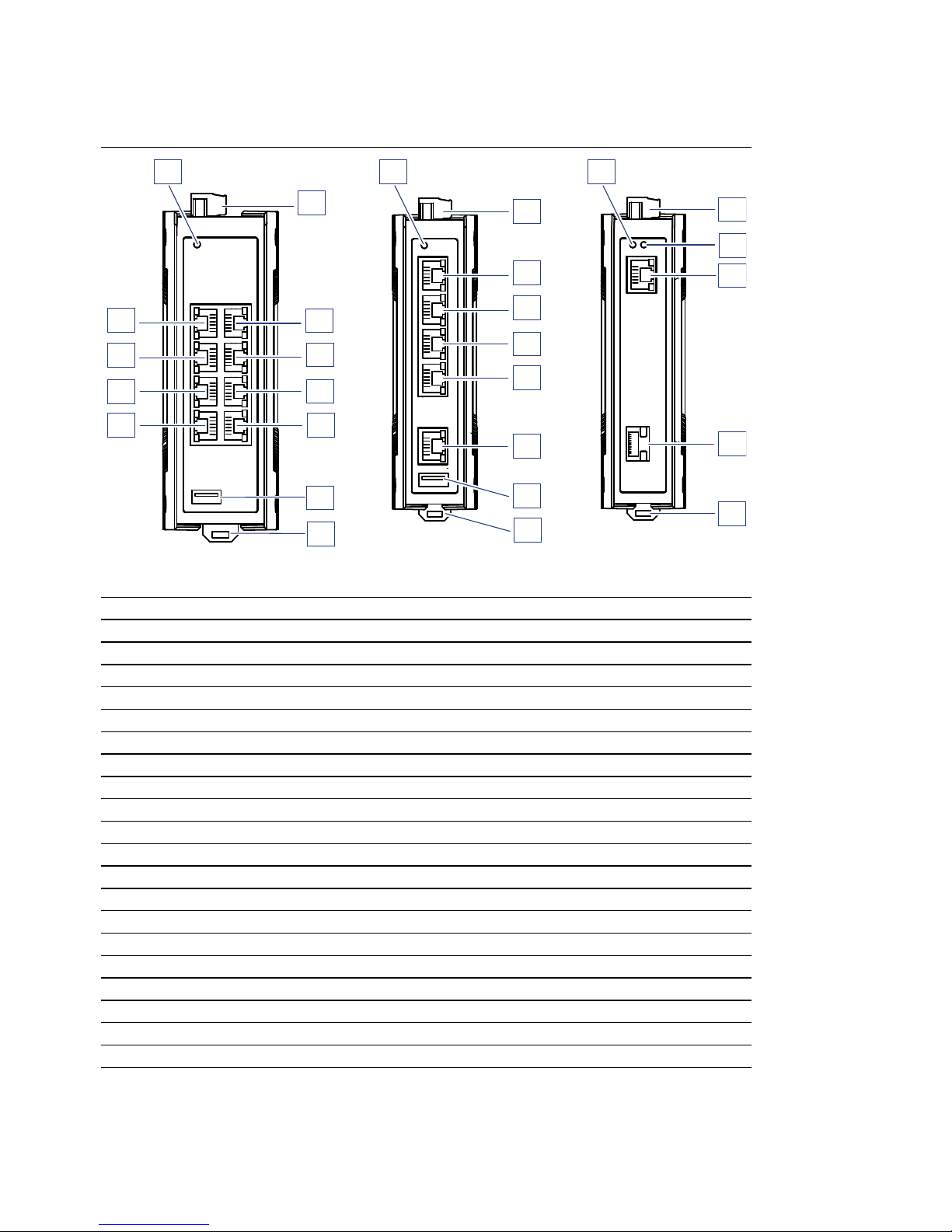
Front view using example of device variants SPIDER-PL-40...
SPIDER-PL-40-08T1...
1 LED display elements for device status
2 6-pin, pluggable terminal block for power supply and signal contact
3 ... 6 4 × RJ45 socket for 10/100/1000 Mbit/s Twisted Pair connections
7USB interface
8 Rail lock gate for DIN rail mounting
9 ... 12 4 × RJ45 socket for 10/100/1000 Mbit/s Twisted Pair connections
SPIDER-PL-40-05T1...
1 LED display elements for device status
2 6-pin, pluggable terminal block for power supply and signal contact
3 ... 7 5 × RJ45 socket for 10/100/1000 Mbit/s Twisted Pair connections
8USB interface
9 Rail lock gate for DIN rail mounting
SPIDER-PL-40-01T1...
1 LED display elements for device status
2 6-pin, pluggable terminal block for power supply and signal contact
3 LED display elements for port status
4 RJ45 socket for 10/100/1000 Mbit/s Twisted Pair connections
5 SFP slot for 100/1000 Mbit/s F/O connections
6 Rail lock gate for DIN rail mounting
2
3
4
5
6
2
3
4
5
6
7
8
1
9
SPIDER-PL-40-05T1...
SPIDER-PL-40-01T1...
1
7
2
3
4
5
6
8
SPIDER-PL-40-08T1...
1212
1111
1010
9
1
Page 15
Installation SPIDER-PL
Release 03 08/2016
15
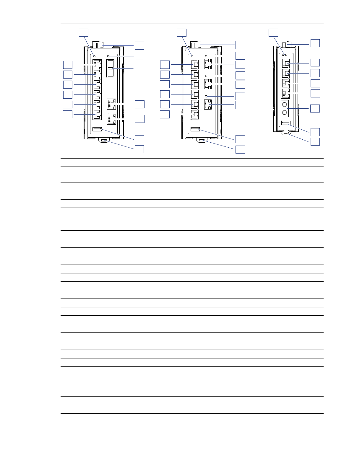
Front view using example of device variants SPIDER-PL-20...
SPIDER-PL-20-08T1...
(depending on the device variant)
1 LED display elements for device status
2 6-pin, pluggable terminal block for power supply and signal contact
3 LED display elements for port status
4 depending on device variant
DSC multimode socket for 100 Mbit/s F/O connections
DSC singlemode socket for 100 Mbit/s F/O connections
5 ... 6 2 × RJ45 socket for 10/100 Mbit/s twisted pair connections
7 USB interface
8 Rail lock gate for DIN rail mounting
9 ... 14 6 × RJ45 socket for 10/100 Mbit/s twisted pair connections
SPIDER-PL-20-06T1...
1 LED display elements for device status
2 6-pin, pluggable terminal block for power supply and signal contact
3, 5, 7 LED display elements for port status
4, 6, 8 SFP slot for 100 Mbit/s F/O connections
9 USB interface
10 Rail lock gate for DIN rail mounting
11 ... 16 6 × RJ45 socket for 10/100 Mbit/s twisted pair connections
SPIDER-PL-20-04T1...
1 LED display elements for device status
2 6-pin, pluggable terminal block for power supply and signal contact
3 ... 6 4 × RJ45 socket for 10/100 Mbit/s twisted pair connections
7 depending on device variant
ST multimode socket for 100 Mbit/s F/O connections
DSC multimode socket for 100 Mbit/s F/O connections
DSC singlemode socket for 100 Mbit/s F/O connections
8 USB interface
9 Rail lock gate for DIN rail mounting
SPIDER-PL-20-06T1...
SPIDER-PL-20-04T1
...
SPIDER-PL-20-08T1...
1010
9
14
14
13
12
12
1111
1
7
2
3
4
5
6
8
1
1616
1515
1414
1313
1212
1111
9
2
4
5
6
7
8
1010
3
2
3
4
5
6
7
8
9
1
Page 16

16
Installation SPIDER-PL
Release 03 08/2016
1.4 Power supply
You have the following options to supply your device with voltage:
Power supply via a 6-pin terminal block
A 6-pin terminal block is available for the power supply to the device.
You will find more information here:
See “Installing terminal blocks, switching on the supply voltage” on
page 28.
1.5 Ethernet ports
You can connect end devices and other segments to the device ports using
twisted pair cables or optical fibers (F/O).
You find information on pin assigments for making patch cables here:
“Pin assignments” on page 17
10/100/1000 Mbit/s twisted pair port
This port is an RJ45 socket.
The 10/100/1000 Mbit/s twisted pair port offers you the ability to connect
network components according to the IEEE 802.3 10BASE-T/100BASETX/1000BASE-T standard.
This port supports:
Autonegotiation
Autopolarity
Autocrossing (if autonegotiation is activated)
1000 Mbit/s half duplex, 1000 Mbit/s full duplex
100 Mbit/s half-duplex mode, 100 Mbit/s full duplex mode
10 Mbit/s half-duplex mode, 10 Mbit/s full duplex mode
10/100 Mbit/s twisted pair port
This port is an RJ45 socket.
The 10/100 Mbit/s twisted pair port offers you the ability to connect
network components according to the IEEE 802.3 10BASE-T/100BASETX standard.
This port supports:
Autonegotiation
Autopolarity
Autocrossing (if autonegotiation is activated)
100 Mbit/s half-duplex mode, 100 Mbit/s full duplex mode
10 Mbit/s half-duplex mode, 10 Mbit/s full duplex mode
Page 17

Installation SPIDER-PL
Release 03 08/2016
17
100/1000 Mbit/s F/O port
This port is an SFP slot.
The 100/1000 Mbit/s F/O port offers you the ability to connect network
components according to the IEEE 802.3 100BASE-FX/1000BASESX/1000BASE-LX standard.
This port supports:
1000 Mbit/s full duplex when using a Gigabit Ethernet SFP transceiver
100 Mbit/s half duplex, 100 Mbit/s full duplex when using a Fast
Ethernet SFP transceiver
100 Mbit/s F/O port
The 100 Mbit/s F/O port offers you the ability to connect network
components according to the IEEE 802.3 100BASE-FX standard.
This port supports:
100 Mbit/s half-duplex mode, 100 Mbit/s full duplex mode
State on delivery:
100 Mbit/s, full duplex
1.5.1 Pin assignments
RJ45 Pin 10/100 Mbit/s 1000 Mbit/s
MDI mode
1 TX+ BI_DA+
2TX− BI_DA−
3 RX+ BI_DB+
4 — BI_DC+
5— BI_DC−
6RX− BI_DB−
7 — BI_DD+
8— BI_DD−
MDI-X mode
1 RX+ BI_DB+
2RX− BI_DB−
3 TX+ BI_DA+
4 — BI_DD+
5— BI_DD−
6TX− BI_DA−
7 — BI_DC+
8— BI_DC−
1
2
3
4
5
6
7
8
Page 18

18
Installation SPIDER-PL
Release 03 08/2016
1.6 Display elements
After the supply voltage is switched on, the device performs a self-test.
During this process, various LEDs light up.
1.6.1 Device state
These LEDs provide information about conditions which affect the operation
of the whole device.
LED Display Color Activity Meaning
Power Supply voltage — None Supply voltage is too low
Yellow Lights up Device variants with redundant power
supply:
Supply voltage 1 or 2 is on
Green Lights up Device variants with redundant power
supply:
Supply voltages 1 and 2 are on
Page 19

Installation SPIDER-PL
Release 03 08/2016
19
1.6.2 Port state
These LEDs display port-related information.
SP
(data rate)
Color Activity Meaning
— None Device detects an invalid or missing
link
Yellow Flashes 1 time a period 10 Mbit/s connection
Yellow Flashing 2 times a
period
100 Mbit/s connection
Yellow Flashes 3 times a
period
1000 Mbit/s connection
LS/DA
(link status/data)
Color Activity Meaning
— None Device detects an invalid or missing
link
Green Lights up Device detects a valid link
Green flashing Device is transmitting and/or
receiving data
yellow/greenFlashing alternately Update of the configuration via the
USB interface
SPSP
LS/DALS/DA
Page 20

20
Installation SPIDER-PL
Release 03 08/2016
2 Configuration interface
2.1 USB interface
The USB interface allows you to connect the a storage medium. This is for
transfering configuration data.
The USB interface has the following properties:
Connectors: type A
Supports the USB master mode
Supports USB 2.0
Supplies current of max. 500 mA
Voltage not potential-separated
1
2
3
4
Pin
1
2
3
4
Function
VCC (VBus)
- Data
+ Data
Ground (GND)
Page 21

Installation SPIDER-PL
Release 03 08/2016
21
3 Signal contact
The potential-free signal contact (relay contact, closed circuit) reports
through a break in contact:
The failure of at least one supply voltage.
The device is not operational.
Connection failure to at least one port.
The link state can be masked for each port using the configuration. In the
state of delivery, link monitoring is inactive.
Figure Pin Function
1 + 24 V DC
2FAULT
30 V
40 V
5FAULT
6 + 24 V DC
+24 V
+24 V
0 V
0 V
Page 22

22
Installation SPIDER-PL
Release 03 08/2016
4 Installation
The devices have been developed for practical application in a harsh
industrial environment.
On delivery, the device is ready for operation.
Perform the following steps to install and configure the device:
Checking the package contents
Mounting the device
Installing an SFP transceiver (optional)
Connecting the terminal block
Operating the device
Connecting data cables
Configuration (optional)
4.1 Checking the package contents
Proceed as follows:
Check whether the package includes all items named in the section
“Scope of delivery” on page 46.
Check the individual parts for transport damage.
Page 23

Installation SPIDER-PL
Release 03 08/2016
23
4.2 Mounting the device
You have the following options for mounting your device:
Installing the device onto the DIN rail
Mounting on a flat surface
4.2.1 Installing the device onto the DIN rail
Prerequisite:
The device is for mounting on a 35 mm DIN rail in accordance with DIN EN
60715.
Proceed as follows:
Slide the upper snap-in guide of the device into the DIN rail.
Use a screwdriver to pull the rail lock gate downwards.
Snap in the device by releasing the rail lock slide.
2
1
Page 24

24
Installation SPIDER-PL
Release 03 08/2016
4.2.2 Mounting on a flat surface
Proceed as follows:
Attach the wall mounting plate to a flat surface of the wall using screws.
You will find the dimensions necessary for mounting the device in the
illustration.
Mount the device on the wall mounting plate. Insert the upper snap-in
guide of the device into the rail and press it down against the rail until it
snaps into place.
Two models of wall mounting plates are available.
See “Accessories” on page 48.
20
0.8
25
1
52,7
2.07
35
1.38
O
6,5
0.26
42
1.65
57,5
2.26
35,75
1.41
24,25
0.95
O
6,5
0
.26
35
1.38
mm
inch
20
0.8
25
1
52,7
2.07
35
1.38
O
6,5
0.26
72
2.83
87,5
3.44
65,75
2.59
54,25
2.14
O
6,5
0.26
35
1.38
mm
inch
Page 25

Installation SPIDER-PL
Release 03 08/2016
25
4.3 Grounding the device
Prerequisite:
Use a wire diameter for the ground conductor that is no smaller than the
diameter of the supply voltage connection, however of at least 0.5 mm²
(AWG20).
Proceed as follows:
Ground the device via the ground screw.
The grounding screw is located on the topside as shown in the illustration.
Page 26

26
Installation SPIDER-PL
Release 03 08/2016
4.4 Installing an SFP transceiver (optional)
Prerequisite:
Use only Hirschmann SFP transceivers which are suitable for usage with
the device.
See “Accessories” on page 48.
Proceed as follows:
Remove the protection cap from the SFP transceiver.
Push the transceiver with the lock closed into the slot until it latches in.
Page 27

Installation SPIDER-PL
Release 03 08/2016
27
4.5 Connecting the terminal block
The supply voltage can be connected redundantly. Both inputs are
uncoupled. There is no distributed load. With redundant supply, the power
supply unit with the higher output voltage supplies the device on its own. The
supply voltage is electrically isolated from the housing.
For the supply voltage to be connected, perform the following steps:
Remove the power connector from the device.
Connect the wires according to the pin assignment on the device with the
clamps.
Note: With a non-redundant supply of the supply voltage, the device reports
the loss of a supply voltage. You can prevent this message by applying the
supply voltage via both inputs, or by changing the configuration.
WARNING
ELECTRIC SHOCK
Connect only a supply voltage that corresponds to the type plate of your
device.
Never insert sharp objects (small screwdrivers, wires, etc.) into the
connection terminals for electric conductors, and do not touch the terminals.
Observe the maximum values for the contact load of the signal contact.
Failure to follow these instructions can result in death, serious injury,
or equipment damage.
Figure Pin Function
1 + 24 V DC
2FAULT
30 V
40 V
5FAULT
6 + 24 V DC
+24 V
+24 V
0 V
0 V
Page 28

28
Installation SPIDER-PL
Release 03 08/2016
4.6 Operating the device
Perform the following steps to start up the device:
Installing terminal blocks, switching on the supply voltage
Connecting data cables
4.6.1 Installing terminal blocks, switching on the supply
voltage
By connecting the supply voltage via the terminal block, you start the
operation of the device.
4.6.2 Connecting data cables
Note the following general recommendations for data cable connections in
environments with high electrical interference levels:
Keep the length of the data cables as short as possible.
Use optical data cables for the data transmission between the buildings.
When using copper cables, provide a sufficient separation between the
power supply cables and the data cables. Ideally, install the cables in
separate cable channels.
Verify that power supply cables and data cables do not run parallel over
longer distances, and that ideally they are installed in separate cable
channels. If reducing the inductive coupling is necessary, verify that the
power supply cables and data cables cross at a 90° angle.
Use shielded cables (SF/UTP cables as per ISO/IEC 11801:2002).
Connect the data cables according to your requirements.
Page 29

Installation SPIDER-PL
Release 03 08/2016
29
5 Configuration (optional)
With its default settings, the device is ready for operation ex works.
You have the option to change the settings according to your requirements
using the USB interface.
You will find the configuration parameters in a separate overview.
See table 2 on page 31.
Prerequisite:
Install the Switch Programming Tool on your computer. You can download
the software for free on the internet from the Hirschmann product pages:
www.hirschmann.com/en/QR/SPIDER-PL-Downloads .
Proceed as follows:
Connect a storage medium to your PC.
Start the Switch Programming Tool.
Select your device variant from the drop-down list “Device Type”.
Page 30

30
Installation SPIDER-PL
Release 03 08/2016
Modify the parameters in the highlighted areas according to your
requirements.
Save the configuration file to the storage medium.
Disconnect the storage medium from your PC.
You have changed the settings according to your requirements. Transfer
the configuration data to your device by following these steps:
Make sure the device is switched off.
Connect the storage medium to the device.
Switch on the device.
The SPIDER device reads the csv file on the storage medium and adopts
the settings. During this time, the LED “LS/DA” flashes alternately in
yellow/green.
Page 31

Installation SPIDER-PL
Release
03
08/2016
31
Parameter Values Default values Comment
global PSU alarm PSU 1/2 enabled / disabled PSU 1 / 2 enabled
Aging time Aging time in s 300 s
QoS 802.1p mapping VLAN Priority 0 ... 7
Traffic Class 0 ... 3
VLAN Priority
0
1
2
3
4
5
6
7
Traffic Class
1
0
0
1
2
2
3
3
QoS DSCP mapping DSCP value 0 ... 63
Traffic Class 0 ... 3
See table 3.
per port Flow control enabled / disabled disabled
Port admin state enabled / disabled enabled
Jumbo frames enabled / disabled disabled Only on GE ports
Broadcast storm protection enabled / disabled disabled Ingress filtering
Broadcast storm threshold 0% ... 100% 100%
Multicast storm protection enabled / disabled disabled Ingress filtering
Multicast storm threshold 0% ... 100% 100%
QoS Trust Mode untrusted, trustDot1p, trustIpDscp trustDot1 This also includes VLAN 0 mode for
Profinet applications.
Port based priority 0 .. 7 0
Link alarm enabled / disabled disabled
Table 2: Configuration parameters
Page 32

32
Installation SPIDER-PL
Release
03
08/2016
per TP port Autonegotiation enabled / disabled enabled
Speed 100 Mbit/s, 10 Mbit/s 100 Mbit/s Only if autonegotiation is disabled,
no forced mode 1000 Mbit/s
Duplex mode FDX / HDX FDX Only if autonegotiation is disabled
Autocrossing enabled / disabled enabled Only if autonegotiation is disabled
MDI state MDI-X MDI-X Only if autonegotiation is disabled
EEE enabled / disabled disabled Only for GE ports
per Fiber
port
Duplex mode FDX / HDX FDX
d2/d1 0 1 2 3 4 5 6
0: 1001233
1: 1001233
2: 1002233
3: 1002233
4: 101223
5: 101223
6: 101223
7: 101223
8: 001233
9: 001233
Table 3: DSCP mapping table
Table 2: Configuration parameters
Page 33

Installation SPIDER-PL
Release 03 08/2016
33
5.1 Configuration readout
You have the option to read out the configuration using a storage medium.
Proceed as follows:
Create a text file in the root directory of the storage medium.
Rename the text file to “ShowRunningConfiguration.txt”.
Connect the storage medium to the device.
Restart the device by disconnecting the power supply for a moment.
When the text file “ShowRunningConfiguration.txt” in the root directory
of the device is found, the device creates a file with the current
configuration.
You will find this file in the root directory of the storage medium under the
name “RunningConfig.txt”.
Page 34

34
Installation SPIDER-PL
Release 03 08/2016
6 Monitoring the ambient air temperature
Operate the device below the specified maximum ambient air temperature
exclusively.
See “General technical data” on page 38.
The ambient air temperature is the temperature of the air at a distance of 2 in
(5 cm) from the device. It depends on the installation conditions of the device,
e.g. the distance from other devices or other objects, and the output of
neighboring devices.
Page 35

Installation SPIDER-PL
Release 03 08/2016
35
7 Maintenance and service
When designing this device, Hirschmann largely avoided using high-wear
parts. The parts subject to wear and tear are dimensioned to last longer
than the lifetime of the product when it is operated normally. Operate this
device according to the specifications.
Relays are subject to natural wear. This wear depends on the frequency
of the switching operations. Check the resistance of the closed relay
contacts and the switching function depending on the frequency of the
switching operations.
Depending on the degree of pollution in the operating environment, check
at regular intervals that the ventilation slots in the device are not
obstructed.
Note: You will find information about the complaints and returns procedures
on the Internet under
http://www.beldensolutions.com/en/Service/Repairs/index.phtml .
Page 36

36
Installation SPIDER-PL
Release 03 08/2016
8 Disassembly
8.1 Removing an SFP transceiver (optional)
Proceed as follows:
Pull the SFP transceiver out of the slot by means of the opened lock.
Close the SFP transceiver with the protective cap.
1
2
Page 37

Installation SPIDER-PL
Release 03 08/2016
37
8.2 Removing the device
Proceed as follows:
Disconnect the data cables.
Disable the supply voltage.
Disconnect the terminal blocks.
Disconnect the grounding.
Insert a screwdriver horizontally below the housing into the locking gate.
Without tilting the screwdriver, pull the locking gate down and tilt the
device upwards.
WARNING
ELECTRIC SHOCK
Disconnect the grounding only after disconnecting all other cables.
Failure to follow these instructions can result in death, serious injury,
or equipment damage.
2
1
Page 38

38
Installation SPIDER-PL
Release 03 08/2016
9 Technical data
General technical data
Dimensions
W × H × D
SPIDER-PL-20... See “Dimension drawings” on
page 39.
SPIDER-PL-40...
Power supply Rated voltage range DC 9.6 V DC ... 32 V DC
9.6 V DC ... 60 V DC
Rated voltage range AC 18 V AC ... 30 V AC
Connection type 6-pin terminal block for the
supply voltage
Power loss buffer > 10 ms
Back-up fuse ≤ 4 A, slow blow
“FAULT”
signal contact
Switching current max. 1 A, SELV
Switching voltage max. 60 V DC or max. 30 V AC,
SELV
Climatic
conditions during
operation
Ambient air temperature
a
a. Temperature of the ambient air at a distance of 2 inches (5 cm) from the device
−40 °F ... +158 °F
(−40 °C ... +70 °C)
Derating
b
b. For device variant SPIDER-PL-20-06T1Z6Z6Z6TZ9HHHH, the maximum permitted
ambient air temperature has to be reduced to 140 °F (60 °C).
Humidity 10 % ... 95 %
Air pressure minimum 700 hPa
(+9842 ft; +3000 m)
Climatic
conditions during
storage
Ambient air temperature
a
−40 ºF ... +185 ºF
(−40 ºC ... +85 ºC)
Humidity 10 % ... 95 %
(non-condensing)
Air pressure minimum 700 hPa
(+9842 ft; +3000 m)
Pollution degree 2
Protection classes Laser protection Class 1 in compliance with IEC
60825-1
Degree of protection IP40
Page 39

Installation SPIDER-PL
Release 03 08/2016
39
Dimension drawings
Figure 1: Dimensions of device variants SPIDER-PL-20...
SPIDER-PL-20-04T1...
135
5.3
39
1.5
9,9
0.3
mm
inch
113
4.4
4,2
0.1
18
0.7
135
5.3
56
2.2
9,9
0.3
SPIDER-PL-20-08T1...
135
5.3
56
2.2
9,9
0.3
SPIDER-PL-20-06T1...
Page 40

40
Installation SPIDER-PL
Release 03 08/2016
Figure 2: Dimensions of device variants SPIDER-PL-40...
18
0.7
113
4.4
4,2
0.1
mm
inch
135
5.3
49
1.9
9,9
0.3
SPIDER-PL-40-08T1...
SPIDER-PL-40-05T1...
135
5.3
39
1.5
9,9
0.3
SPIDER-PL-40-01T1...
135
5.3
39
1.5
9,9
0.3
Page 41

Installation SPIDER-PL
Release
03
08/2016
41
EMC
EMC interference emission Standard
applications
a
a. EN 61131-2, CE, FCC – applies to all devices
Merchant Navy
b
b. Merchant Navy – applies to devices with the approval codes WU, U9, UY, UX, UT, VU
Railway
applications
(trackside)
c
c. EN 50121-4 – applies to devices with the approval codes UT, T9, TY, VT, R9, RT, RY
Sub-station
applications
d
d. EN 61850-3, IEEE 1613 – applies to devices with the approval codes V9, VY, VU, VT, R9
Radiated emission
EN 55022 Class A Class A Class A Class A
GL Guidelines — EMC 1 — —
FCC 47 CFR Part 15 Class A Class A Class A Class A
EN 61000-6-4 Fulfilled Fulfilled Fulfilled Fulfilled
Conducted emission
EN 55022 Supply connection Class A Class A Class A Class A
GL Guidelines Supply connection — EMC 1 — —
FCC 47 CFR Part 15 Supply connection Class A Class A Class A Class A
EN 61000-6-4 Supply connection Fulfilled Fulfilled Fulfilled Fulfilled
EN 55022 Telecommunication
connections
Class A Class A Class A Class A
EN 61000-6-4 Telecommunication
connections
Fulfilled Fulfilled Fulfilled Fulfilled
EMC interference immunity Standard
applications
a
Marine
applications
b
Railway
applications
(trackside)
c
Sub-station
applications
d
Electrostatic discharge
EN 61000-4-2
IEEE C37.90.3
Contact discharge ±4kV ± 6kV ± 6kV ±8kV
EN 61000-4-2
IEEE C37.90.3
Air discharge ±8kV ±8kV ±8kV ±15kV
Page 42

42
Installation SPIDER-PL
Release
03
08/2016
Electromagnetic field
EN 61000-4-3 10 V/m 10 V/m 20 V/m 10 V/m
IEEE 1613 — — — 35 V/m
Fast transients (burst)
EN 61000-4-4
IEEE C37.90.1
Supply connection ± 2 kV ± 2 kV ± 2 kV ± 4 kV
EN 61000-4-4
IEEE C37.90.1
Data line ±4kV ±4kV ± 2kV ±4kV
Voltage surges - DC supply connection
EN 61000-4-5 line/ground ± 2 kV ± 2 kV ± 2 kV ± 2 kV
IEEE 1613 line/ground — — — ± 5 kV
EN 61000-4-5 line/line ± 1 kV ± 1 kV ± 1 kV ± 1 kV
Voltage surges - data line
EN 61000-4-5 line/ground ± 1 kV ± 1 kV ± 2 kV ± 2 kV
Conducted disturbances
EN 61000-4-6 150 kHz ... 80 MHz 10 V 10 V 10 V 10 V
Damped vibration – DC supply connection
EN 61000-4-12
IEEE C37.90.1
line/ground — — — 2.5 kV
EN 61000-4-12
IEEE C37.90.1
line/line — — — 1 kV
Damped oscillation - data line
EN 61000-4-12
IEEE C37.90.1
line/ground — — — 2.5 kV
EN 61000-4-12 line/line — — — ± 1 kV
Pulse magnetic fields
EN 61000-4-9 — — 300 A/m —
EMC interference immunity Standard
applications
a
Marine
applications
b
Railway
applications
(trackside)
c
Sub-station
applications
d
Page 43

Installation SPIDER-PL
Release
03
08/2016
43
Stability Standard
applications
a
Marine
applications
b
Railway
applications
(trackside)
c
Sub-station
applications
d
IEC 60068-2-6, test Fc Vibration 5 Hz ... 8.4 Hz with
0.14 in. (3.5 mm)
amplitude
2 Hz ... 13.2 Hz
with
0.04 in. (1 mm)
amplitude
— 2 Hz ... 9 Hz with
0.12 in. (3 mm)
amplitude
8.4 Hz ... 150 Hz
with 1 g
13.2 Hz ... 200 Hz
with 0.7 g
— 9 Hz ... 200 Hz
with 1 g
— — — 200 Hz ... 500 Hz
with 1.5 g
IEC 60068-2-27, test Ea Shock 15 g at 11 ms — — 10 g at 11 ms
Page 44

44
Installation SPIDER-PL
Release 03 08/2016
Network range
Note: The line lengths specified for the transceivers apply for the
respective fiber data (fiber attenuation and BLP/dispersion).
Product
code
M-SFP-...
Wave
length
Fiber System
attenuatio
n
Example
for F/O
line length
a
a. including 3 dB system reserve when compliance with the fiber data is observed
Fiber
attenuatio
n
BLPb/
dispersion
b. Using the bandwidth length product is inappropriate for expansion calculations.
-SX/LC... MM 850 nm 50/125 µm 0-7.5 dB 0-550 m 3.0 dB/km 400 MHz×km
-SX/LC... MM 850 nm 62.5/125 µm 0-7.5 dB 0-275 m 3.2 dB/km 200 MHz×km
-MX/LC
EEC
MM 1310 nm 50/125 µm 0-12 dB 0-1.5 km 1.0 dB/km 800 MHz×km
-MX/LC
EEC
MM 1310 nm 62.5/125 µm 0-12 dB 0-500 m 1.0 dB/km 500 MHz×km
-LX/LC... MM 1310 nm
c
c. With F/O adapter compliant with IEEE 802.3-2002 clause 38 (single-mode fiber offset-
launch mode conditioning patch cord)
50/125 µm 0-10.5 dB 0-550 m 1.0 dB/km 800 MHz×km
-LX/LC... MM 1310 nm
c
62.5/125 µm 0-10.5 dB 0-550 m 1.0 dB/km 500 MHz×km
-LX/LC... SM 1310 nm 9/125 µm 0-10.5 dB 0-20 km
d
d. Including 2.5 dB system reserve when compliance with the fiber data is observed
0.4 dB/km 3.5 ps/(nm×km)
-LX+/LC... SM 1310 nm 9/125 µm 5-20 dB 14-42 km 0.4 dB/km 3.5 ps/(nm×km)
-LH/LC... LH 1550 nm 9/125 µm 5-22 dB 23-80 km 0.25 dB/km 19 ps/(nm×km)
-LH+/LC LH 1550 nm 9/125 µm 15-30 dB 71-108 km 0.25 dB/km 19 ps/(nm×km)
-LH+/LC LH 1550 nm 9/125 µm 15-30 dB 71-128 km 0.21 dB/km
(typically)
19 ps/(nm×km)
Table 4: Fiber port 1000BASE-FX (SFP fiber optic Gigabit Ethernet Transceiver)
Product
code
M-SFPBIDI...
Wave
length
TX
Wave
length
RX
Fiber System
attenuat
ion
Example
for F/O
line
length
a
a. including 3 dB system reserve when compliance with the fiber data is observed
Fiber
attenuatio
n
Dispersion
Type A
LX/LC
EEC
SM 1310 nm 1550 nm 9/125 µm 0-11 dB 0-20 km 0.4 dB/km 3.5 ps/(nm×km)
Type B
LX/LC
EEC
SM 1550 nm 1310 nm 9/125 µm 0-11 dB 0-20 km 0.25 dB/km 19 ps/(nm×km)
Type A
LH/LC
EEC
LH 1490 nm 1590 nm 9/125 µm 5-24 dB 23-80 km 0.25 dB/km 19 ps/(nm×km)
Type B
LH/LC
EEC
LH 1590 nm 1490 nm 9/125 µm 5-24 dB 23-80 km 0.25 dB/km 19 ps/(nm×km)
Table 5: F/O port (bidirectional Gigabit Ethernet SFP Transceiver)
Page 45

Installation SPIDER-PL
Release 03 08/2016
45
MM = Multimode, SM = Singlemode, LH = Singlemode Longhaul
Product
code
M-FASTSFP-...
Wave
length
Fiber System
attenuatio
n
Example
for F/O line
length
a
a. including 3 dB system reserve when compliance with the fiber data is observed
Fiber
attenuation
BLP/
dispersion
-MM/LC... MM 1310 nm 50/125 µm 0-8 dB 0-5 km 1.0 dB/km 800 MHz×km
-MM/LC... MM 1310 nm 62.5/125 µm 0-11 dB 0-4 km 1.0 dB/km 500 MHz×km
-SM/LC... SM 1310 nm 9/125 µm 0-13 dB 0-25 km 0.4 dB/km 3.5 ps/(nm×km)
-SM+/LC... SM 1310 nm 9/125 µm 10-29 dB 25-65 km 0.4 dB/km 3.5 ps/(nm×km)
-LH/LC... SM 1550 nm 9/125 µm 10-29 dB 47-104 km 0.25 dB/km 19 ps/(nm×km)
-LH/LC... SM 1550 nm 9/125 µm 10-29 dB 55-140 km 0.18 dB/km
b
b. with ultra-low-loss optical fiber
18 ps/(nm×km)
Table 6: Fiber port 100BASE-FX (SFP fiber optic Fast Ethernet Transceiver)
Product
code
Wave
length
Fiber System
attenuatio
n
Example
for F/O line
length
a
a. including 3 dB system reserve when compliance with the fiber data is observed
Fiber
attenuati
on
BLP/
dispersion
-M2, -M4 MM 1300 nm 50/125 µm 0-8 dB 0-5 km 1.0 dB/km 800 MHz×km
-M2, -M4 MM 1300 nm 62.5/125 µm 0-11 dB 0-4 km 1.0 dB/km 500 MHz×km
-S2 SM 1300 nm 9/125 µm 0-16 dB 0-30 km 0.4 dB/km 3.5 ps/(nm×km)
Table 7: F/O port 100BASE-FX
10/100/1000 Mbit/s twisted pair port
Length of a twisted pair segment max. 100 m (for cat5e cable)
Page 46

46
Installation SPIDER-PL
Release 03 08/2016
Power consumption/power output
Scope of delivery
No. Device name Maximum power
consumption
Maximum power
output
1 SPIDER-PL-20-01.............HH-.. 3.8 W 13.1 BTU(IT)/h
2 SPIDER-PL-20-01.............HV-.. 4.4 W 15.1 BTU(IT)/h
3 SPIDER-PL-20-04.............HH-.. 4.3 W 14.7 BTU(IT)/h
4 SPIDER-PL-20-04.............HV-.. 4.9 W 16.7 BTU(IT)/h
5 SPIDER-PL-20-05.............HH-.. 2.4 W 8.0 BTU(IT)/h
6 SPIDER-PL-20-05.............HV-.. 3.0 W 10.4 BTU(IT)/h
7 SPIDER-PL-20-06.............HH-.. 9.0 W 30.7 BTU(IT)/h
8 SPIDER-PL-20-06.............HV-.. 8.6 W 29.5 BTU(IT)/h
9 SPIDER-PL-20-07.............HH-.. 6.9 W 23.7 BTU(IT)/h
10 SPIDER-PL-20-07.............HV-.. 6.9 W 23.5 BTU(IT)/h
11 SPIDER-PL-20-08...2.........HH-.. 5.0 W 16.9 BTU(IT)/h
12 SPIDER-PL-20-08...2.........HV-.. 5.2 W 17.7 BTU(IT)/h
13 SPIDER-PL-20-08..99.........HH-.. 2.6 W 8.8 BTU(IT)/h
14 SPIDER-PL-20-08..99.........HV-.. 3.1 W 10.6 BTU(IT)/h
15 SPIDER-PL-40-01.............HH-.. 4.0 W 13.8 BTU(IT)/h
16 SPIDER-PL-40-01.............HV-.. 4.7 W 16.0 BTU(IT)/h
17 SPIDER-PL-40-04.............HH-.. 5.9 W 20.0 BTU(IT)/h
18 SPIDER-PL-40-04.............HV-.. 6.1 W 21.0 BTU(IT)/h
19 SPIDER-PL-40-05.............HH-.. 4.3 W 14.8 BTU(IT)/h
20 SPIDER-PL-40-05.............HV-.. 5.0 W 17.0 BTU(IT)/h
21 SPIDER-PL-40-08.............HH-.. 6.0 W 20.4 BTU(IT)/h
22 SPIDER-PL-40-08.............HV-.. 7.9 W 26.8 BTU(IT)/h
Table 8: Power consumption/power output of the device variants SPIDER-PL-20...
and SPIDER-PL-40... .
Number Scope of delivery
1× Device
1 × Terminal block for supply voltage and signal contact
1 × General safety instructions
Page 47

Installation SPIDER-PL
Release 03 08/2016
47
Order number
Device Order number
SPIDER-PL-20-01T1M29999TZ9HHHH 942-141-022
SPIDER-PL-20-01T1S29999TZ9HHHH 942-141-023
SPIDER-PL-20-04T1M29999TZ9HHHH 942-141-024
SPIDER-PL-20-04T1M49999TZ9HHHH 942-141-025
SPIDER-PL-20-04T1S29999TZ9HHHH 942-141-026
SPIDER-PL-20-05T1999999TZ9HHHH 942-141-016
SPIDER-PL-20-06T1Z6Z6Z6TZ9HHHH 942-141-027
SPIDER-PL-20-07T1M2M299TZ9HHHH 942-141-030
SPIDER-PL-20-07T1S2S299TZ9HHHH 942-141-031
SPIDER-PL-20-08T1M29999TZ9HHHH 942-141-028
SPIDER-PL-20-08T1999999TZ9HHHH 942-141-017
SPIDER-PL-20-08T1S29999TZ9HHHH 942-141-029
SPIDER-PL-40-01T1O69999TZ9HHHH 942-141-033
SPIDER-PL-40-04T1O69999TZ9HHHH 942-141-034
SPIDER-PL-40-05T1999999TZ9HHHH 942-141-019
SPIDER-PL-40-08T1999999TZ9HHHH 942-141-020
Page 48

48
Installation SPIDER-PL
Release 03 08/2016
Accessories
Note that products recommended as accessories may have different
characteristics to those of the device, which may limit the application
range of the overall system. For example, if you add an accessory with IP
20 to a device with IP 65, the IP of the overall system is reduced to 20.
Other accessories Order number
6-pin terminal block (50 pcs.) 943 845-013
Rail Power Supply RPS 30 943 662-003
Rail Power Supply RPS 80 EEC 943 662-080
Rail Power Supply RPS 120 EEC (CC) 943 662-121
Wall mounting plate for DIN rail mounting, width 1.58 in. (40 mm) 942 177-001
Wall mounting plate for DIN rail mounting, width 2.76 in. (70 mm) 942 177-002
Fast-Ethernet-SFP-Transceiver Order number
M-FAST SFP-TX/RJ45 942 098-001
M-FAST SFP-TX/RJ45 EEC 942 098-002
M-FAST SFP-MM/LC 943 865-001
M-FAST SFP-MM/LC EEC 943 945-001
M-FAST SFP-SM/LC 943 866-001
M-FAST SFP-SM/LC EEC 943 946-001
M-FAST SFP-SM+/LC 943 867-001
M-FAST SFP-SM+/LC EEC 943 947-001
M-FAST SFP-LH/LC 943 868-001
M-FAST SFP-LH/LC EEC 943 948-001
SFP-FAST-MM/LC
a
a. You will find further information on the certificates on the Internet on the Hirschmann product
pages (www.hirschmann.com).
942 194-001
SFP-FAST-MM/LC EEC
a
942 194-002
SFP-FAST-SM/LC
a
942 195-001
SFP-FAST-SM/LC EEC
a
942 195-002
Bidirectional Gigabit Ethernet SFP transceiver Order number
M-SFP-BIDI Type A LX/LC EEC 943 974-001
M-SFP-BIDI Type B LX/LC EEC 943 974-002
M-SFP-BIDI Type A LH/LC EEC 943 975-001
M-SFP-BIDI Type B LH/LC EEC 943 975-002
M-SFP-BIDI Bundle LX/LC EEC (type A + B) 943 974-101
M-SFP-BIDI Bundle LH/LC EEC (type A + B) 943 975-101
Gigabit Ethernet SFP transceiver Order number
M-SFP-TX/RJ45 943 977-001
M-SFP-SX/LC 943 014-001
M-SFP-SX/LC EEC 943 896-001
M-SFP-MX/LC EEC 942 108-001
M-SFP-LX/LC 943 015-001
M-SFP-LX/LC EEC 943 897-001
Page 49

Installation SPIDER-PL
Release 03 08/2016
49
M-SFP-LX+/LC 942 023-001
M-SFP-LX+/ LC EEC 942 024-001
M-SFP-LH/LC 943 042-001
M-SFP-LH/LC EEC 943 898-001
M-SFP-LH+/LC 943 049-001
SFP-GIG-LX/LC
a
942 196-001
SFP-GIG-LX/LC EEC
a
942 196-002
a. You will find further information on the certificates on the Internet on the Hirschmann product
pages (www.hirschmann.com).
Gigabit Ethernet SFP transceiver Order number
Page 50

50
Installation SPIDER-PL
Release 03 08/2016
Underlying technical standards
The device has an approval based on a specific standard only if the
approval indicator appears on the device casing.
If your device has a shipping approval according to Germanischer Lloyd,
you find the approval mark printed on the device label. You will find out
whether your device has other shipping approvals on the Hirschmann
website under www.hirschmann.com in the product information.
The device generally fulfills the technical standards named in their current
versions.
Standard
ATEX (2014/34/EU) ATEX – Intended use of equipment and protection systems in
potentially explosive areas.
CSA C22.2 No. 142 Canadian National Standard(s) – Process Control Equipment –
Industrial Products
ISA 12.12.01 Nonincendive Electrical Equipment for Use in Class I and II,
Division 2 and Class III, Divisions 1 and 2 Hazardous (Classified)
Locations
ECE Nr. 10 E type approval for use in vehicles
FCC 47 CFR Part 15 Code of Federal Regulations
Germanischer Lloyd Rules for Classification and Construction VI-7-2 – GL
IEC/EN 61850-3 Communication networks and systems in substations – Part 3:
General requirements
IEC 60825-1 Safety of Laser Products
IEEE 1613 IEEE Standard Environmental and Testing Requirements for
Communication Networking Devices in Electric Power Substations
EN 50121-4 Railway applications – EMC – Emission and immunity of the
signaling and telecommunications apparatus (Rail Trackside)
EN 55022 Information technology equipment – Radio disturbance
characteristics – Limits and methods of measurement
EN 60950-1 Information technology equipment – Safety – Part 1: General
requirements
EN 60950-22 Installations of IT equipment – Security – Part 22: Outdoor
equipments
EN 61131-2 Programmable controllers – Part 2: Equipment requirements and
tests
UL/IEC 61010-1,
UL/IEC 61010-2-201
Safety for Control Equipment
NEMA TS 2 Traffic Controller Assemblies with NTCIP Requirements
(environmental requirements)
RCM Australian Regulatory Compliance Mark (RCM)
Australian Radiocommunications Standard 2008,
Radiocommunications Act 1992
Table 9: List of the technical standards
Page 51

Installation SPIDER-PL
Release 03 08/2016
51
A Further Support
Technical Questions
For technical questions, please contact any Hirschmann dealer in your
area or Hirschmann directly.
You will find the addresses of our partners on the Internet at
http://www.hirschmann.com.
A list of local telephone numbers and email addresses for technical
support directly from Hirschmann is available at
https://hirschmann-support.belden.eu.com.
This site also includes a free of charge knowledge base and a software
download section.
Hirschmann Competence Center
The Hirschmann Competence Center is ahead of its competitors:
Consulting incorporates comprehensive technical advice, from system
evaluation through network planning to project planning.
Training offers you an introduction to the basics, product briefing and
user training with certification.
The current technology and product training courses can be found at
http://www.hicomcenter.com
Support ranges from the first installation through the standby service
to maintenance concepts.
With the Hirschmann Competence Center, you have decided against
making any compromises. Our client-customized package leaves you
free to choose the service components you want to use.
Internet:
http://www.hicomcenter.com
Page 52

 Loading...