

Hirschmann RSR20-0900, RSR30-0703, RSR20-0800, RSR30-0603, RSR30-0802 User Manual
Installation RSR20/RSR30
Release 04 10/2015
Technical Support
https://hirschmann-support.belden.eu.com
User Manual
Installation
Industrial Ethernet Rail Switch Rugged
RSR20/RSR30 Family
5
7
9
6
8
10
5
7
9
6
8
10
3
5
7
9
4
6
8
10
3
5
7
9
4
6
8
10
3
5
7
4
6
8
1
3
5
7
2
4
6
8

The naming of copyrighted trademarks in this manual, even when not specially indicated, should
not be taken to mean that these names may be considered as free in the sense of the trademark
and tradename protection law and hence that they may be freely used by anyone.
© 2015 Hirschmann Automation and Control GmbH
Manuals and software are protected by copyright. All rights reserved. The copying, reproduction,
translation, conversion into any electronic medium or machine scannable form is not permitted,
either in whole or in part. An exception is the preparation of a backup copy of the software for
your own use. The end user license on the provided CD/DVD is effective for devices with
embedded software.
The performance features described here are binding only if they have been expressly agreed
when the contract was made. This publication was created by Hirschmann Automation and
Control GmbH to the best of its knowledge. Hirschmann reserves the right to change the content
of this publication at any time without notice. Hirschmann does not give any warranty or
assurance with respect to the correctness or accuracy of the details in this publication.
Hirschmann accepts no liability for damage in any way related to the use of the network
components or their operating system software. In addition, we refer to the conditions of use
specified in the license contract.
You find the latest version of this manual on the internet at Hirschmann product pages
(www.hirschmann.com).
Hirschmann Automation and Control GmbH
Stuttgarter Str. 45-51
72654 Neckartenzlingen
Germany
Tel.: +49 1805 141538
RSR20/RSR30 039 698-002-04-1015

Installation RSR20/RSR30
Release 04 10/2015
3
Content
Safety Information 5
About this manual 14
Key 15
1 Description 16
1.1 General description of the device 16
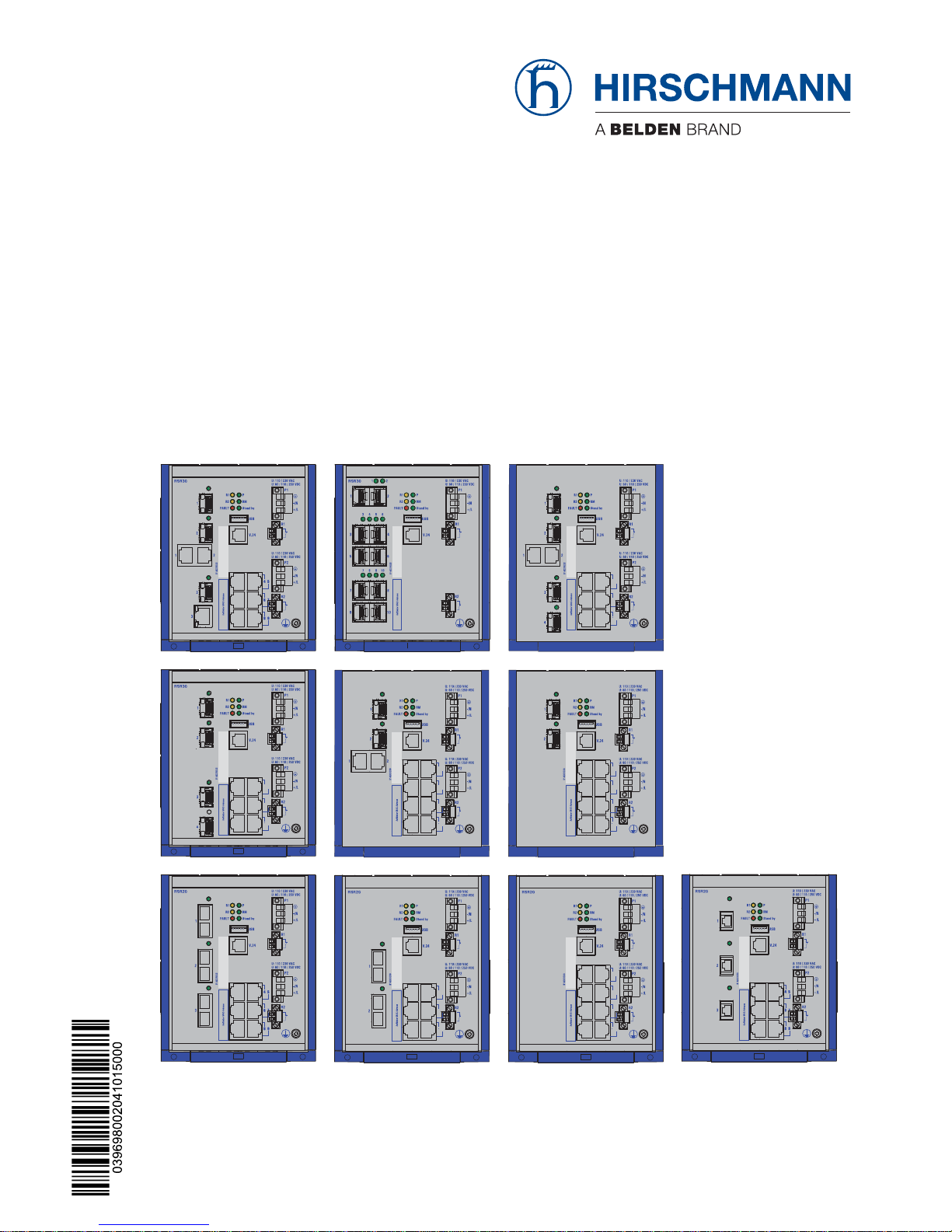
1.2 Description of the device variants 17
1.2.1 Combination options RSR20/RSR30 17
1.2.2 Port number and media for RSR20-... 20
1.2.3 Port number and media for RSR30-... 25
1.3 Power supply 32
1.3.1 Supply voltage with the characteristic value K 32
1.3.2 Supply voltage with the characteristic value C 32
1.4 Ethernet ports 32
1.4.1 10/100/1000 Mbit/s twisted pair port 32
1.4.2 10/100 Mbit/s twisted pair port 33
1.4.3 100/1000 Mbit/s F/O port 33
1.4.4 1000 Mbit/s F/O port 33
1.4.5 100 Mbit/s F/O port 34
1.4.6 Gigabit combo port 34
1.4.7 Pin assignments 35
1.5 Display elements 36
1.5.1 Device status 36
1.5.2 Port status 38
1.6 Management interfaces 39
1.6.1 USB interface 39
1.6.2 V.24 interface (external management) 39
1.7 Signal contacts 40
2 Installation 41
2.1 Checking the package contents 41
2.2 Installing and grounding the device 41
2.2.1 Snapping a unit onto the DIN rail 42
2.2.2 Mounting on a vertical flat surface 43
2.2.3 Grounding 44
2.3 Installing an SFP transceiver (optional) 44
2.4 Connecting the terminal block 44

4
Installation RSR20/RSR30
Release 04 10/2015
2.4.1 Supply voltage 46
2.4.2 Supply voltage with the characteristic value K 46
2.4.3 Supply voltage with the characteristic value C 47
2.4.4 Signal contact 48
2.5 Mounting a terminal block 48
2.6 Operating the device 48
2.7 Connecting data cables 49
2.8 Insert data in label area 49
3 Making basic settings 50
4 Monitoring the ambient air temperature 51
5 Maintenance and service 52
6Disassembly 53
6.1 Removing the device 53
6.2 Removing an SFP transceiver (optional) 53
7 Technical Data 54
A Further support 65
Installation RSR20/RSR30
Release 04 10/2015
5
Safety Informat ion
General safety instructions
You operate this device with electricity. Improper usage of the device
entails the risk of physical injury or significant property damage. The
proper and safe operation of this device depends on proper handling
during transportation, proper storage and installation, and careful
operation and maintenance.
Before connecting any cable, read this document, and the safety
instructions and warnings.
Operate the device with undamaged components exclusively.
The device is free of any service components. In case of a damaged
or malfunctioning device, turn off the supply voltage and return the
device to Hirschmann for inspection.
Intended usage
Use the product only for the application cases described in the
Hirschmann product information, including this manual.
Operate the product only according to the technical specifications.
See “General technical data” on page 54.
Connect to the product only components suitable for the requirements
of the specific application case.
Installation site requirements
Install the device in a fire enclosure according to EN 60950-1.
Install this device only in a switch cabinet or in a restricted access
location, to which maintenance staff have exclusive access.
WARNING
UNCONTROLLED MACHINE ACTIONS
To avoid uncontrolled machine actions caused by data loss, configure all
the data transmission devices individually.
Before you start any machine which is controlled via data transmission, be
sure to complete the configuration of all data transmission devices.
Failure to follow these instructions can result in death, serious injury,
or equipment damage.

6
Installation RSR20/RSR30
Release 04 10/2015
Device casing
Only technicians authorized by the manufacturer are permitted to open
the casing.
Never insert pointed objects (narrow screwdrivers, wires, etc.) into the
device or into the connection terminals for electric conductors. Do not
touch the connection terminals.
Keep the ventilation slits free to ensure good air circulation.
See “General technical data” on page 54.
Install the device in the vertical position.
At ambient temperatures > 60 °C:
The surfaces of the device casing may become hot. Avoid touching the
device while it is operating.
Qualification requirements for personnel
Allow qualified personnel exclusively to perform any work on the
device.
Qualified personnel are characterized by the following points:
The qualified personnel has received an appropriate training. Proper
training as well as a practical knowledge and experience constitute the
qualification. This qualification is the requirement to connect, to ground
and to label power circuits, devices, and systems in accordance with
current safety engineering standards.
The qualified personnel are aware of the hazards associated with their
tasks.
The qualified personnel know proper measures against such hazards
to minimize the risk for themselves and others.
The qualified personnel participate in regular training.
National and international safety regulations
Verify that the electrical installation meets local or nationally applicable
safety regulations.
Grounding
The device is grounded by the separate ground screw on the front panel.
Use a wire diameter for the ground conductor that is no smaller than
the diameter of the supply voltage connection, however of at least
0.75 mm² (AWG18).
Ground the device before connecting any other cables.
Disconnect the grounding only after disconnecting all other cables.
Shielding ground
The overall shield of a connected shielded twisted pair cable is connected
to the ground connector on the front panel as a conductor.
Beware of possible short circuits when connecting a cable section with
conductive shielding braiding.

Installation RSR20/RSR30
Release 04 10/2015
7
Supply voltage
The supply voltage is electrically isolated from the housing.
The devices are designed for operation with safety extra-low voltage.
Connect only safety extra-low voltage circuits with voltage restrictions
in line with IEC/EN 60950-1 to the supply voltage connections and
signal contacts.
Connect only a supply voltage that corresponds to the type plate of
your device.
Ground the device before connecting any other cables.
Only for device variants featuring supply voltage with the characteristic
value K:
Before connecting the electrical wires, always verify that all the
following requirements are met:
The power supply conforms to overvoltage category I or II.
The voltage supply has an easily accessible disconnecting device
(e.g. a switch or a plug). This disconnecting device is clearly
identified. So in the case of an emergency, it is clear which
disconnecting device belongs to which power supply cable.
The electrical wires are voltage-free.
Supply with AC voltage:
A fuse is located in the outer conductor of the power supply.
The neutral conductor is on ground potential at both voltage inputs.
Otherwise, a fuse is also located in the neutral conductor.
Regarding the properties of this fuse: See “General technical data”
on page 54.
Supply with DC voltage:
A fuse suitable for DC voltage is located in the plus conductor of the
power supply.
The minus conductor is on ground potential. Otherwise, a fuse is
also located in the minus conductor.
Regarding the properties of this fuse: See “General technical data”
on page 54.
The wire diameter of the power supply cable is at least 0.75 mm²
(North America: AWG18) on the supply voltage input.
The cross-section of the protective conductor is the same size as
or bigger than the cross-section of the power supply cables.
The cables used are permitted for the temperature range of the
application case.
Relevant for North America:
The power supply cables are suitable for ambient air temperatures
of at least 167 °F (75 °C). The wires of the power supply cables are
made of copper.
Start connecting the electrical wires only if all the above safety
requirements are fulfilled.

8
Installation RSR20/RSR30
Release 04 10/2015
Only for device variants featuring supply voltage with the characteristic
value C:
The power supply is Class 2 compliant.
The power supply conforms to overvoltage category I or II.
The voltage supply has an easily accessible disconnecting device
(e.g. a switch or a plug). This disconnecting device is clearly
identified. So in the case of an emergency, it is clear which
disconnecting device belongs to which power supply cable.
The electrical wires are voltage-free.
A fuse suitable for DC voltage is located in the plus conductor of the
power supply.
The minus conductor is on ground potential. Otherwise, a fuse is
also located in the minus conductor.
Regarding the properties of this fuse: See “General technical data”
on page 54.
The wire diameter of the power supply cable is at least 0.75 mm²
(North America: AWG18) on the supply voltage input.
The cables used are permitted for the temperature range of the
application case.
Relevant for North America:
The power supply cables are suitable for ambient air temperatures
of at least 167 °F (75 °C). The wires of the power supply cables are
made of copper.
Start connecting the electrical wires only if all the above safety
requirements are fulfilled.
Internal fuses are only triggered if there is a fault in the device. In case
of damage or malfunction of the device, turn off the supply voltage and
return the device to the plant for inspection.
For supply voltage connections with protective conductor connection:
First connect the protective conductor before connecting the wires for
the supply voltage.
If your device comprises a 2nd supply voltage connection of this type:
First connect the protective conductor before connecting the wires for
the supply voltages.
Enable the supply voltage for the device only when the following
requirements are fulfilled:
the housing is closed
the terminal blocks are wired correctly
the terminal blocks for the power supply are connected

Installation RSR20/RSR30
Release 04 10/2015
9
Relevant for use in explosion hazard areas (Hazardous
Locations, Class I, Division 2):
SUITABLE FOR USE IN CLASS I, DIVISION 2, GROUPS A, B, C AND D
HAZARDOUS LOCATIONS, OR IN NON-HAZARDOUS LOCATIONS
ONLY.
Substitution of any components may impair suitability for Class I,
Division 2.
The USB connector is for temporary connection only. Do not use,
connect or disconnect unless the area is known to be non-hazardous.
Connection or disconnection in an explosive atmosphere could result in
an explosion.
Do not disconnect equipment unless power has been turned off or the
area is known to be free of ignitable concentrations.
Avertissement - Risque d'explosion - Ne pas débrancher tant que le
circuit est sous tension à moins que l'emplacement soit connu pour ne
contenir aucune concentration de gaz inflammable.
Avertissement - Risque d'explosion - La substitution de tout composant
peut rendre ce matériel incompatible pour une utilisation en classe I,
division 2.

10
Installation RSR20/RSR30
Release 04 10/2015
Title: Control Drawing for RSR20 / RSR30 family
Date: 2010-01-20 Document No.: 000144941DNR
Rev.
1.1
Page 1 of 2
5
7
9
6
8
10
P1
P2
Fault
Fault
IP54 enclosure
HAZARDOUS LOCATION
Non
Hazardous
Location
1
RSRxx
Non-Hazardous LocationHazardous Location
Power supply (redundant)
Type “K”: 110–230 V AC or 60–250 V DC
Type “C”: 24–48 V DC
(protective earthing conductors Type “K” only)
Fault contacts. Equipment with nonincendive eld wiring parameters:
V < 30 V I < 90 mA L
i
< 0.5 ȝH C
i
< 20 pF
Data communication Ethernet Ports
ACA21 USB AutoCon guration Adapter
For Maintenance only – See Installation Instructions
V.24 Interface (External Management)
Installation RSR20/RSR30
Release 04 10/2015
11
Title: Control Drawing for RSR20 / RSR30 family
Date: 2010-01-20 Document No.: 000144941DNR
Rev.
1.1
Page 2 of 2
1
Notes:
The nonincendive eld wiring circuit concept allows interconnection of nonincendive eld wiring apparatus and associated nonin
cendive eld wiring apparatus using any of the wiring methods permitted for unclassi ed locations when certain parameter condi
tions are met.
C
a
C
i
+ C
Cable
; L
a
L
i
+ L
Cable
Nonincendive field wiring circuits must be wired in accordance with the National Electrical Code (NEC), NFPA 70, article 501.
Nonincendive Field Wiring Parameters:
Entity Parameters for
Class I, Division 2 Groups A, B, C, D
V
max
[V]
I
max
[mA]
C
i
[pF]
L
i
[ȝH]
Connector: Contacts:
30 90 20 0.5
2 pole Fault contacts
WARNING!
EXPLOSION HAZARD – SUBSTITUTION OF ANY COMPONENTS MAY IMPAIR SUITABILITY FOR HAZARDOUS
LOCATIONS OR EXPLOSIVE ATMOSPHERES.
WARNING – EXPLOSION HAZARD – DO NOT DISCONNECT EQUIPMENT UNLESS POWER HAS BEEN SWITCHED OFF
OR THE AREA IS KNOWN TO BE NON-HAZARDOUS.
DO NOT OPEN WHEN ENERGIZED.

12
Installation RSR20/RSR30
Release 04 10/2015
Casing
Only technicians authorized by the manufacturer are permitted to open
the casing.
Never insert pointed objects (narrow screwdrivers, wires, etc.) into the
device or into the connection terminals for electric conductors. Do not
touch the connection terminals.
Keep the ventilation slits free to ensure good air circulation.
See “General technical data” on page 54.
Install the device in the vertical position.
At ambient temperatures > 60 °C:
The surfaces of the device casing may become hot. Avoid touching the
device while it is operating.
CE marking
The labeled devices comply with the regulations contained in the following
European directive(s):
In accordance with the above-named EU directive(s), the EU conformity
declaration will be at the disposal of the relevant authorities at the
following address:
Hirschmann Automation and Control GmbH
Stuttgarter Str. 45-51
72654 Neckartenzlingen
Tel.: +49 1805 141538
The product can be used in the industrial sector.
Interference immunity: EN 61000-6-2
Emitted interference: EN 55022
Safety: EN 60950-1
The assembly guidelines provided in these instructions must be strictly
adhered to in order to observe the EMC threshold values.
Device variant Directive
All variants 2011/65/EU (RoHS)
Directive of the European Parliament and of the Council on the
restriction of the use of certain hazardous substances in
electrical and electronic equipment.
2004/108/EG (EMV)
Directive of the European Parliament and the council for
standardizing the regulations of member states with regard to
electromagnetic compatibility.
Only for device variants
featuring supply voltage with
the characteristic value K:
2011/65/EU (RoHS)
Directive of the European Parliament and of the Council on the
restriction of the use of certain hazardous substances in
electrical and electronic equipment.

Installation RSR20/RSR30
Release 04 10/2015
13
Warning! This is a class A device. This device can cause interference in
living areas, and in this case the operator may be required to take
appropriate measures.
LED or laser components
LED or LASER components according to IEC 60825-1 (2014):
CLASS 1 LASER PRODUCT
CLASS 1 LED PRODUCT
FCC note
This device complies with part 15 of the FCC rules. Operation is subject
to the following two conditions: (1) this device may not cause harmful
interference; (2) this device must accept any interference received,
including interference that may cause undesired operation.
Appropriate testing has established that this device fulfills the
requirements of a class A digital device in line with part 15 of the FCC
regulations.
These requirements are designed to provide sufficient protection against
interference where the device is being used in a business environment.
The device creates and uses high frequencies and can also radiate these
frequencies. If it is not installed and used in accordance with this
operating manual, it can cause radio transmission interference. The use
of this device in a residential area can also cause interference, and in this
case the user is obliged to cover the costs of removing the interference.
Recycling note
After usage, this device must be disposed of properly as electronic waste,
in accordance with the current disposal regulations of your county, state,
and country.

14
Installation RSR20/RSR30
Release 04 10/2015
About this manual
The document “User Manual Installation” contains a device description,
safety instructions, a description of the display and further information that
you need to install the device before you start its configuration.
The following manuals are available as PDF files on the CD-ROM supplied:
“Installation” user manual
“Basic Configuration” user manual
“Redundancy Configuration” user manual
“Graphical User Interface” reference manual
“Command Line Interface” reference manual
The Industrial HiVision Network Management Software provides you with
additional options for smooth configuration and monitoring:
ActiveX control for SCADA integration
Auto-topology discovery
Browser interface
Client/server structure
Event handling
Event log
Simultaneous configuration of multiple devices
Graphical user interface with network layout
SNMP/OPC gateway

Installation RSR20/RSR30
Release 04 10/2015
15
Key
The symbols used in this manual have the following meanings:
List
Work step
Subheading

16
Installation RSR20/RSR30
Release 04 10/2015
1 Description
1.1 General description of the device
You can choose from between a wide range of variants. You have the option
to set up your device individually based on different criteria:
Number of Ports
Data Rate
Types of connectors
Temperature range
Supply voltage range
Approvals
The RSR20/RSR30 devices are designed for the special requirements of
industrial automation. They meet the relevant industry standards, provide
very high operational reliability, even under extreme conditions, and also
long-term reliability and flexibility.
The devices allow you to set up switched industrial Ethernet networks that
conform to the IEEE 802.3 standard.
The devices work without a fan.
If desired, the power is supplied redundantly.
The following installation options are available:
simply snapping them onto a DIN rail
Mounting on a flat surface
You have the option of choosing various media to connect to the end devices
and other network components:
twisted pair cable
multimode F/O
singlemode F/O
The ring redundancy concept allows the network to be reconfigured quickly
after a failure.
This gives you a quick overview of the product configuration through:
diagnosis displays
displaying the operating parameters
a label area for the IP address
There are convenient options for managing the device. Administer your
devices via:
a Web browser
Telnet
SSH

Installation RSR20/RSR30
Release 04 10/2015
17
HiDiscovery (Software for commissioning the device)
A network management software (e.g., Industrial HiVision)
a V.24 interface (locally on the device)
The devices provide you with a large range of functions, which the manuals
for the operating software inform you about. You will find these manuals in
the form of PDF files on the enclosed CD/DVD; it is also available for
downloading on the Internet on the Hirschmann product pages
(www.hirschmann.com).
The Hirschmann network components help you ensure continuous
communication across all levels of the enterprise.
1.2 Description of the device variants
The RSR20 device variants are Rugged Rail Switches with 8 to 9 Fast
Ethernet ports (10/100 Mbit/s).
The RSR30 device variants are Rugged Rail Switches with 2 to 3 Gigabit
Ethernet ports (1000 Mbit/s) and 6 to 8 Fast Ethernet ports (10/100 Mbit/s).
1.2.1 Combination options RSR20/RSR30
The product designation of your device is made from combining the desired
product characteristics in accordance with the following table. The short
designation is in column 3.
You have numerous options of combining the device characteristics. You can
determine the possible combinations using the configurator which is
available in the Belden E-Catalog (www.e-catalog.beldensolutions.com) on
the web page of the device.

18
Installation RSR20/RSR30
Release 04 10/2015
Position Characteristic Charac
teristic
value
Property
1 to 5 Product RSR20 Rail Switch Rugged without gigabit ports
RSR30 Rail Switch Rugged with gigabit ports
6 - (hyphen) 7 to 8 Number of 100 Mbit/s
ports
06 6 × 100 Mbit/s Ethernet
07 7 × 100 Mbit/s Ethernet
08 8 × 100 Mbit/s Ethernet
09 9 × 100 Mbit/s Ethernet
9 and 10 Number of
1000 Mbit/s ports
00 0 × 1000 Mbit/s Ethernet
02 2 × 1000 Mbit/s Ethernet
03 3 × 1000 Mbit/s Ethernet
11 and 12 Port 1 and 2 or Port 1 CC 2 × Combo-Port 100/1000 Mbit/s Ethernet
OO 2 × SFP slot 1000 Mbit/s Ethernet
MM 2 × Multimode FX (DSC)
JJ 2 × Multimode FX (MTRJ)
NN 2 × Multimode FX (ST)
VV 2 × Singlemode FX (DSC)
UU 2 × Singlemode FX (ST)
LL 2 × Singlemode Long Haul FX (DSC)
GG 2 × Singlemode Long Haul FX (DSC) 200 km
O7 1 × Combo-Port 100/1000 Mbit/s Ethernet
O6 1 × SFP slot 1000 Mbit/s Ethernet
T1 1 × Twisted Pair TX (RJ45 socket)
M2 1 × Multimode FX (DSC)
M3 1 × Multimode FX (MTRJ)
M4 1 × Multimode FX (ST)
S2 1 × Singlemode FX (DSC)
S4 1 × Singlemode FX (ST)
L2 1 × Singlemode Long Haul FX (DSC)
G2 1 × Singlemode Long Haul FX (DSC) 200 km
Table 1: Combination options for the RSR20/RSR30 device variants

Installation RSR20/RSR30
Release 04 10/2015
19
13 and 14 Port 2 or Port 3 or
Port 3 and 4
ZZ 2 × SFP slot (100 Mbit/s)
O7 1 × Combo-Port 100/1000 Mbit/s Ethernet
O6 1 × SFP slot 1000 Mbit/s Ethernet
T1 1 × Twisted Pair TX (RJ45 socket)
M2 1 × Multimode FX (DSC)
M3 1 × Multimode FX (MTRJ)
M4 1 × Multimode FX (ST)
S2 1 × Singlemode FX (DSC)
S4 1 × Singlemode FX (ST)
L2 1 × Singlemode Long Haul FX (DSC)
G2 1 × Singlemode Long Haul FX (DSC) 200 km
15 and 16 Remaining ports T1 1 × Twisted Pair TX (RJ45 socket)
Z6 1 × SFP slot (100 Mbit/s)
17 Temperature range S Standard +32 °F to +140 °F (0 °C to +60 °C)
U Extended −40 °F to +185 °F (−40 °C to +85 °C )
F Extended −40 °F to +185 °F (−40 °C to +85 °C )
and conformal coating
18 Voltage range 1 C See “General technical data” on page 54.
K See “General technical data” on page 54.
19 Voltage range 2 9 Not present
C See “General technical data” on page 54.
K See “General technical data” on page 54.
20 Approvals H CE; UL508; GL; IEC61850; IEEE 1613 substation;
EN 50121-4 railway (along track)
C CE; UL508; GL; IEC61850; IEEE 1613 substation;
EN 50121-4 railway (along track)
21 Software variant P Professional
Position Characteristic Charac
teristic
value
Property
Table 1: Combination options for the RSR20/RSR30 device variants

20
Installation RSR20/RSR30
Release 04 10/2015
1.2.2 Port number and media for RSR20-...
To put together your personal RSR20 device in the above table (see table 1),
you have the following combination options
(“?” = any value from the “Characteristic value column):
Position
1 to 10
Position
11 to 12
Position
13 to 14
Position
15 to 16
Position17Position
18 to 19
Position
20 to 21
RSR20-0900 JJ M3 T1 ? KK, K9, KC, CC ?P
-“- MM M2, M4, S2,
S4, L2, G2
-“- -“- -“- -“-
-“- NN -“- -“- -“- -“- -“-
-“- VV -“- -“- -“- -“- -“-
-“- UU -“- -“- -“- -“- -“-
-“- LL -“- -“- -“- -“- -“-
-“- GG -“- -“- -“- -“- -“-
Table 2: Combination options for RSR20-0900...
Position
1 to 10
Position
11 to 12
Position
13 to 14
Position
15 to 16
Position17Position
18 to 19
Position
20 to 21
RSR20-0800 T1 T1 T1 ? KK, K9, KC, CC ?P
-“- M2 M2, M4, S2,
S4, L2, G2
-“- -“- -“- -“-
-“- M4 -“- -“- -“- -“- -“-
-“- S2 -“- -“- -“- -“- -“-
-“- S4 -“- -“- -“- -“- -“-
-“- L2 -“- -“- -“- -“- -“-
-“- G2 -“- -“- -“- -“- -“-
Table 3: Combination options for RSR20-0800...
 Loading...