

Page 1

User Manual
Basic Configuration
Industrial ETHERNET (Gigabit) Switch
RS20/RS30/RS40, MS20/MS30, OCTOPUS, PowerMICE,
RSR20/RSR30, MACH 100, MACH 1000, MACH 4000
Basic Configuration
Release 6.0 07/2010
Technical Support
HAC.Support@Belden.com
Page 2

The naming of copyrighted trademarks in this manual, even when not specially indicated, should
not be taken to mean that these names may be considered as free in the sense of the trademark
and tradename protection law and hence that they may be freely used by anyone.
© 2010Hirschmann Automation and Control GmbH
Manuals and software are protected by copyright. All rights reserved. The copying, reproduction,
translation, conversion into any electronic medium or machine scannable form is not permitted,
either in whole or in part. An exception is the preparation of a backup copy of the software for
your own use. For devices with embedded software, the end-user license agreement on the
enclosed CD applies.
The performance features described here are binding only if they have been expressly agreed
when the contract was made. This document was produced by Hirschmann Automation and
Control GmbH according to the best of the company's knowledge. Hirschmann reserves the right
to change the contents of this document without prior notice. Hirschmann can give no guarantee
in respect of the correctness or accuracy of the information in this document.
Hirschmann can accept no responsibility for damages, resulting from the use of the network
components or the associated operating software. In addition, we refer to the conditions of use
specified in the license contract.
You can get the latest version of this manual on the Internet at the Hirschmann product site
(www.hirschmann-ac.de).
Printed in Germany
Hirschmann Automation and Control GmbH
Stuttgarter Str. 45-51
72654 Neckartenzlingen
Germany
Tel.: +49 1805 141538
Rel. 6.0 1-01-07/2010 13.7.10
Page 3

Contents
Contents
About this Manual 9
Key 11
Introduction 13
1 Access to the user interfaces 15
1.1 System Monitor 16
1.2 Command Line Interface 18
1.3 Web-based Interface 21
2 Entering the IP Parameters 25
2.1 IP Parameter Basics 27
2.1.1 IP address (version 4) 27
2.1.2 Netmask 28
2.1.3 Classless Inter-Domain Routing 31
2.2 Entering IP parameters via CLI 33
2.3 Entering the IP Parameters via HiDiscovery 36
2.4 Loading the system configuration from the ACA 39
2.5 System configuration via BOOTP 41
2.6 System Configuration via DHCP 46
2.7 System Configuration via DHCP Option 82 49
2.8 Web-based IP Configuration 50
2.9 Faulty Device Replacement 52
3 Loading/saving settings 53
3.1 Loading settings 54
3.1.1 Loading from the local non-volatile memory 55
3.1.2 Loading from the AutoConfiguration Adapter 55
3.1.3 Loading from a file 56
3.1.4 Resetting the configuration to the state on delivery 58
3.2 Saving settings 59
3.2.1 Saving locally (and on the ACA) 59
Basic Configuration
Release 6.0 07/2010
3
Page 4

Contents
3.2.2 Saving to a file on URL 60
3.2.3 Saving to a binary file on the PC 61
3.2.4 Saving as a script on the PC 62
4 Loading Software Updates 63
4.1 Loading the Software manually from the ACA 65
4.1.1 Selecting the software to be loaded 66
4.1.2 Starting the software 67
4.1.3 Performing a cold start 67
4.2 Automatic software update by ACA 68
4.3 Loading the software from the tftp server 70
4.4 Loading the Software via File Selection 72
5 Configuring the Ports 73
6 Protection from Unauthorized Access 77
6.1 Protecting the device 78
6.2 Password for SNMP access 79
6.2.1 Description of password for SNMP access 79
6.2.2 Entering the password for SNMP access 80
6.3 Telnet/Web/SSH Access 84
6.3.1 Description of Telnet Access 84
6.3.2 Description of Web Access 84
6.3.3 Description of SSH Access 85
6.3.4 Enabling/disabling Telnet/Web/SSH Access 85
6.4 Restricted Management Access 87
6.5 HiDiscovery Access 89
6.5.1 Description of the HiDiscovery Protocol 89
6.5.2 Enabling/disabling the HiDiscovery Function 89
6.6 Port Authentication IEEE 802.1X 94
6.6.1 Description of Port Authentication according to
IEEE 802.1X 94
6.6.2 Authentication Process according to IEEE 802.1X 95
6.6.3 Preparing the Device for the
IEEE 802.1X Port Authentication 95
6.6.4 IEEE 802.1X Settings 96
7 Synchronizing the System Time in the Network 97
7.1 Entering the Time 98
Basic Configuration
4
Release 6.0 07/2010
Page 5

Contents
7.2 SNTP 100
7.2.1 Description of SNTP 100
7.2.2 Preparing the SNTP Configuration 101
7.2.3 Configuring SNTP 102
7.3 Precision Time Protocol 106
7.3.1 Description of PTP Functions 106
7.3.2 Preparing the PTP Configuration 110
7.3.3 Application Example 112
7.4 Interaction of PTP and SNTP 117
8 Network Load Control 119
8.1 Direct Packet Distribution 120
8.1.1 Store-and-forward 120
8.1.2 Multi-Address Capability 120
8.1.3 Aging of Learned Addresses 121
8.1.4 Entering Static Addresses 122
8.1.5 Disabling the Direct Packet Distribution 123
8.2 Multicast Application 125
8.2.1 Description of the Multicast Application 125
8.2.2 Example of a Multicast Application 126
8.2.3 Description of IGMP Snooping 127
8.2.4 Setting IGMP Snooping 128
8.2.5 Description of GMRP 133
8.2.6 Setting GMRP 135
8.3 Rate Limiter 137
8.3.1 Description of the Rate Limiter 137
8.3.2 Rate Limiter Settings (PowerMICE and MACH 4000) 138
8.3.3 Rate Limiter settings for
RS20/RS30/40, MS20/MS30, RSR20/RSR30,
MACH 100, MACH 1000 and OCTOPUS 139
8.4 QoS/Priority 141
8.4.1 Description of Prioritization 141
8.4.2 VLAN tagging 142
8.4.3 IP ToS / DiffServ 144
8.4.4 Management prioritization 148
8.4.5 Handling of Received Priority Information 148
8.4.6 Handling of Traffic Classes 149
8.4.7 Setting prioritization 149
8.5 Flow Control 154
8.5.1 Description of Flow Control 154
8.5.2 Setting the Flow Control 156
8.6 VLANs 157
Basic Configuration
Release 6.0 07/2010
5
Page 6

Contents
8.6.1 VLAN Description 157
8.6.2 Examples of VLANs 158
9 Operation Diagnosis 175
9.1 Sending Traps 176
9.1.1 List of SNMP Traps 177
9.1.2 SNMP Traps during Boot 178
9.1.3 Configuring Traps 179
9.2 Monitoring the Device Status 181
9.2.1 Configuring the Device Status 182
9.2.2 Displaying the Device Status 183
9.3 Out-of-band Signaling 184
9.3.1 Controlling the Signal Contact 185
9.3.2 Monitoring the Device Status via the Signal Contact 185
9.3.3 Monitoring the Device Functions via the Signal
Contact 186
9.3.4 Monitoring the Fan 187
9.4 Port Status Indication 190
9.5 Event Counter at Port Level 191
9.5.1 Detecting Non-matching Duplex Modes 192
9.6 Displaying the SFP Status 196
9.7 TP Cable Diagnosis 197
9.8 Topology Discovery 198
9.8.1 Description of Topology Discovery 198
9.8.2 Displaying the Topology Discovery Results 200
9.9 Detecting IP Address Conflicts 203
9.9.1 Description of IP Address Conflicts 203
9.9.2 Configuring ACD 204
9.9.3 Displaying ACD 205
9.10 Detecting Loops 206
9.11 Reports 207
9.12 Monitoring Data Traffic at Ports (Port Mirroring) 209
9.13 Syslog 212
Basic Configuration
6
Release 6.0 07/2010
Page 7

Contents
9.14 Event Log 215
A Setting up the Configuration Environment 217
B General Information 239
C Index 247
D Further Support 251
Basic Configuration
Release 6.0 07/2010
7
Page 8

Contents
Basic Configuration
8
Release 6.0 07/2010
Page 9

About this Manual
About this Manual
The “Basic Configuration” user manual contains the information you need to
start operating the device. It takes you step by step from the first startup
operation through to the basic settings for operation in your environment.
The following thematic sequence has proven itself in practice:
X Set up device access for operation by entering the IP parameters
X Check the status of the software and update it if necessary
X If a configuration already exists, load/store it
X Configure the ports
X Set up protection from unauthorized access
X Optimize the data transmission with network load control
X Synchronize system time in the network
X Function diagnosis
X Store the newly created configuration to nonvolatile memory
The “Installation” user manual contains a device description, safety
instructions, a description of the display, and the other information that you
need to install the device.
The “Redundancy Configuration” user manual contains the information you
need to select a suitable redundancy procedure and configure that
procedure.
The “Industry Protocols” user manual describes how the device is connected
by means of a communication protocol commonly used in the industry, such
as EtherNet/IP and PROFINET IO.
The "Web-based Interface" reference manual contains detailed information
on using the Web interface to operate the individual functions of the device.
Basic Configuration
Release 6.0 07/2010
9
Page 10

About this Manual
The "Command Line Interface" reference manual contains detailed
information on using the Command Line Interface to operate the individual
functions of the device.
The Network Management Software HiVision/Industrial HiVision provides
you with additional options for smooth configuration and monitoring:
X Configuration of multiple devices simultaneously.
X Graphical interface with network layouts.
X Auto-topology discovery.
X Event log.
X Event handling.
X Client / Server structure.
X Browser interface
X ActiveX control for SCADA integration
X SNMP/OPC gateway
10
Basic Configuration
Release 6.0 07/2010
Page 11

Key
Key
The designations used in this manual have the following meanings:
X List
Work step
Link Indicates a cross-reference with a stored link
Note: A note emphasizes an important fact or draws your
Courier ASCII representation in user interface
Execution in the Web-based Interface user interface
Execution in the Command Line Interface user interface
Subheading
attention to a dependency.
Symbols used:
WLAN access point
Router with firewall
Switch with firewall
Router
Switch
Basic Configuration
Release 6.0 07/2010
11
Page 12
Key
Bridge
Hub
A random computer
Configuration Computer
Server
PLC Programmable logic
controller
I/O Robot
12
Basic Configuration
Release 6.0 07/2010
Page 13

Introduction
Introduction
The device has been developed for practical application in a harsh industrial
environment. Accordingly, the installation process has been kept simple.
Thanks to the selected default settings, you only have to enter a few settings
before starting to operate the device.
Note: The changes you make in the dialogs are copied into the volatile
memory of the device when you click on "Set".
To save the changes into the permanent memory of the device select the
non-volatile memory location in the Basic Settings:Load/Save dialog
and click "Save".
Basic Configuration
Release 6.0 07/2010
13
Page 14

Introduction
14
Basic Configuration
Release 6.0 07/2010
Page 15

Access to the user interfaces
1 Access to the user interfaces
The device has 3 user interfaces, which you can access via different
interfaces:
X System monitor via the V.24 interface (out-of-band)
X Command Line Interface (CLI) via the V.24 connection (out-of-band) as
well as Telnet or SSH (in-band)
X Web-based interface via Ethernet (in-band).
Basic Configuration
Release 6.0 07/2010
15
Page 16

Access to the user interfaces
1.1 System Monitor
The system monitor enables you to
X select the software to be loaded
X perform a software update
X start the selected software
X shut down the system monitor
X delete the configuration saved and
X display the boot code information.
1.1 System Monitor
Opening the system monitor
Use the terminal cable (see accessories) to connect
– the V.24 socket (RJ11) to
– a terminal or a COM port of a PC with terminal emulation based on
VT100
(for the physical connection, see the "Installation" user manual).
Speed 9,600 Baud
Data 8 bit
Parity none
Stopbit 1 bit
Handshake off
Table 1: Data transfer parameters
Start the terminal program on the PC and set up a connection with the
device.
When you boot the device, the message
"Press <1> to enter System Monitor 1"
appears on the terminal.
16
Basic Configuration
Release 6.0 07/2010
Page 17

Access to the user interfaces
< Device Name (Boot) Release: 1.00 Build: 2005-09-17 15:36 >
Press <1> to enter System Monitor 1 ...
1
1.1 System Monitor
Figure 1: Screen display during the boot process
Press the <1> key within one second to start system monitor 1.
System Monitor
(Selected OS: L3P-01.0.00-K16 (2005-10-31 19:32))
1 Select Boot Operating System
2 Update Operating System
3 Start Selected Operating System
4 End (reset and reboot)
5 Erase main configuration file
sysMon1>
Figure 2: System monitor 1 screen display
Select a menu item by entering the number.
To leave a submenu and return to the main menu of system monitor 1,
press the <ESC> key.
Basic Configuration
Release 6.0 07/2010
17
Page 18

Access to the user interfaces
1.2 Command Line Interface
1.2 Command Line Interface
The Command Line Interface enables you to use the functions of the device
via a local or remote connection.
The Command Line Interface provides IT specialists with a familiar
environment for configuring IT devices.
The script compatibility of the Command Line Interface enables you, among
other things, to feed multiple devices with the same configuration data, to
create and apply partial configurations or to compare 2 configuration by
comparing the script files.
You will find a detailed description of the Command Line Interface in the
"Command Line Interface" reference manual.
You can access the Command Line Interface via
X the V.24 port (out-of-band)
X Telnet (in-band)
X SSH (in-band)
Note: To facilitate making entries, CLI gives you the option of abbreviating
keywords. Type in the beginning of a keyword. When you press the tab key,
CLI completes the keyword.
Opening the Command Line Interface
Connect the device to a terminal or to the COM port of a PC using
terminal emulation based on VT100 and press any key (see on
page 16 “Opening the system monitor“) or
call up the Command Line Interface via Telnet.
A window for entering the user name appears on the screen.
Up to five users can access the Command Line Interface.
18
Basic Configuration
Release 6.0 07/2010
Page 19

Access to the user interfaces
Copyright (c) 2004-2009 Hirschmann Automation and Control GmbH
All rights reserved
PowerMICE Release L3P-05.1.00
(Build date 2009-10-11 12:13)
System Name: PowerMICE
Mgmt-IP : 10.0.1.105
1.Router-IP: 0.0.0.0
Base-MAC : 00:80:63:51:74:00
System Time: 2009-10-11 13:14:15
User:
1.2 Command Line Interface
Figure 3: Logging in to the Command Line Interface program
Enter a user name. The default setting for the user name is admin .
Press the Enter key.
Enter the password. The default setting for the password is private .
Press the Enter key.
You can change the user name and the password later in the
Command Line Interface.
Please note that these entries are case-sensitive.
The start screen appears.
Basic Configuration
Release 6.0 07/2010
19
Page 20

Access to the user interfaces
NOTE: Enter '?' for Command Help. Command help displays all options
that are valid for the 'normal' and 'no' command forms. For
the syntax of a particular command form, please consult the
documentation.
(Hirschmann Product) >
1.2 Command Line Interface
Figure 4: CLI screen after login
20
Basic Configuration
Release 6.0 07/2010
Page 21

Access to the user interfaces
1.3 Web-based Interface
1.3 Web-based Interface
The user-friendly Web-based interface gives you the option of operating the
device from any location in the network via a standard browser such as
Mozilla Firefox or Microsoft Internet Explorer.
As a universal access tool, the Web browser uses an applet which
communicates with the device via the Simple Network Management Protocol
(SNMP).
The Web-based interface allows you to graphically configure the device.
Opening the Web-based Interface
To open the Web-based interface, you need a Web browser (a program
that can read hypertext), for example Mozilla Firefox version 1 or later, or
Microsoft Internet Explorer version 6 or later.
Note: The Web-based interface uses Java software 6 (“Java™ Runtime
Environment Version 1.6.x”).
Install the software from the enclosed CD-ROM. To do this, you go to
“Additional Software”, select Java Runtime Environment and click on
“Installation”.
Figure 5: Installing Java
Basic Configuration
Release 6.0 07/2010
21
Page 22

Access to the user interfaces
1.3 Web-based Interface
Start your Web browser.
Check that you have activated JavaScript and Java in your browser
settings.
Establish the connection by entering the IP address of the device
which you want to administer via the Web-based management in the
address field of the Web browser. Enter the address in the following
form:
http://xxx.xxx.xxx.xxx
The login window appears on the screen.
Figure 6: Login window
Select the desired language.
In the drop-down menu, you select
– user, to have read access, or
– admin, to have read and write access
to the device.
The password "public", with which you have read access, appears in
the password field. If you wish to have write access to the device, then
highlight the contents of the password field and overwrite it with the
password "private" (default setting).
Click on OK.
Basic Configuration
22
Release 6.0 07/2010
Page 23

Access to the user interfaces
1.3 Web-based Interface
The website of the device appears on the screen.
Note: The changes you make in the dialogs are copied to the device
when you click "Set". Click "Reload" to update the display.
Note: You can block your access to the device by entering an incorrect
configuration.
Activating the function "Cancel configuration change" in the "Load/Save"
dialog enables you to return automatically to the last configuration after a
set time period has elapsed. This gives you back your access to the
device.
Basic Configuration
Release 6.0 07/2010
23
Page 24

Access to the user interfaces
1.3 Web-based Interface
24
Basic Configuration
Release 6.0 07/2010
Page 25

Entering the IP Parameters
2 Entering the IP Parameters
The IP parameters must be entered when the device is installed for the first
time.
The device provides 7 options for entering the IP parameters during the first
installation:
X Entry using the Command Line Interface (CLI).
You choose this “out of band” method if
X you preconfigure your device outside its operating environment
X you do not have network access (“in-band”) to the device
(see page 33 “Entering IP parameters via CLI“).
X Entry using the HiDiscovery protocol.
You choose this “in-band” method if the device is already installed in the
network or if you have another Ethernet connection between your PC and
the device
(see page 36 “Entering the IP Parameters via HiDiscovery“).
X Configuration using the AutoConfiguration Adapter (ACA).
You choose this method if you are replacing a device with a device of the
same type and have already saved the configuration on an ACA(see
page 39 “Loading the system configuration from the ACA“).
X Using BOOTP.
You choose this “in-band” method if you want to configure the installed
device using BOOTP. You need a BOOTP server for this. The BOOTP
server assigns the configuration data to the device using its MAC address
(see page 41 “System configuration via BOOTP“). Because the device is
delivered with “DHCP mode” as the entry for the configuration data
reference, you have to reset this to the BOOTP mode for this method.
X Configuration via DHCP.
You choose this “in-band” method if you want to configure the installed
device using DHCP. You need a DHCP server for this. The DHCP server
assigns the configuration data to the device using its MAC address or its
system name (see page 46 “System Configuration via DHCP“).
Basic Configuration
Release 6.0 07/2010
25
Page 26

Entering the IP Parameters
X Using DHCP Option 82.
You choose this “in-band” method if you want to configure the installed
device using DHCP Option 82. You need a DHCP server with Option 82
for this. The DHCP server assigns the configuration data to the device
using its physical connection (see page 49 “System Configuration via
DHCP Option 82“).
X Configuration via the Web-based interface.
If the device already has an IP address and can be reached via the
network, then the Web-based interface provides you with another option
for configuring the IP parameters.
26
Basic Configuration
Release 6.0 07/2010
Page 27

Entering the IP Parameters
2.1 IP Parameter Basics
2.1 IP Parameter Basics
2.1.1 IP address (version 4)
The IP addresses consist of 4 bytes. These 4 bytes are written in decimal
notation, separated by a decimal point.
Since 1992, five classes of IP address have been defined in the RFC 1340.
Class Network
address
A 1 byte 3 bytes 1.0.0.0 to 126.255.255.255
B 2 bytes 2 bytes 128.0.0.0 to 191.255.255.255
C 3 bytes 1 byte 192.0.0.0 to 223.255.255.255
D 224.0.0.0 to 239.255.255.255
E 240.0.0.0 to 255.255.255.255
Table 2: IP address classes
Host address Address range
The network address is the fixed part of the IP address. The worldwide
leading regulatory board for assigning network addresses is the IANA
(Internet Assigned Numbers Authority). If you require an IP address block,
contact your Internet service provider. Internet service providers should
contact their local higher-level organization:
X APNIC (Asia Pacific Network Information Center) - Asia/Pacific Region
X ARIN (American Registry for Internet Numbers) - Americas and Sub-
Sahara Africa
X LACNIC (Regional Latin-American and Caribbean IP Address Registry) –
Latin America and some Caribbean Islands
X RIPE NCC (Réseaux IP Européens) - Europe and Surrounding Regions
Basic Configuration
Release 6.0 07/2010
27
Page 28

Entering the IP Parameters
Net ID - 7 bits Host ID - 24 bits0
I
I
I
0
I
III
0
III0
Net ID - 14 bits
Net ID - 21 bits
Multicast Group ID - 28 bits
reserved for future use - 28 b its
Class A
Class B
Host ID - 16 bits
Host ID - 8 bit s
Class C
Class D
Class E
2.1 IP Parameter Basics
Figure 7: Bit representation of the IP address
An IP address belongs to class A if its first bit is a zero, i.e. the first decimal
number is less than 128. The IP address belongs to class B if the first bit is a
one and the second bit is a zero, i.e. the first decimal number is between 128
and 191. The IP address belongs to class C if the first two bits are a one, i.e.
the first decimal number is higher than 191.
Assigning the host address (host id) is the responsibility of the network
operator. He alone is responsible for the uniqueness of the IP addresses he
assigns.
2.1.2 Netmask
Routers and gateways subdivide large networks into subnetworks. The
netmask assigns the IP addresses of the individual devices to a particular
subnetwork.
The division into subnetworks with the aid of the netmask is performed in
much the same way as the division of the network addresses (net id) into
classes A to C.
The bits of the host address (host id) that represent the mask are set to one.
The remaining bits of the host address in the netmask are set to zero (see
the following examples).
28
Basic Configuration
Release 6.0 07/2010
Page 29

Entering the IP Parameters
255.255.192.0
Decimal notation
11111111.11111111.11000000.00000000
Binary notation
Subnetwork mask bits
Class B
129.218.65.17
Decimal notation
10000001.11011010.01000001.00010001
binary notation
128 < 129 ≤ 191 ➝ Class B
Subnetwork 1
Network address
129.218.129.17
Decimal notation
10000001.11011010.10000001.00010001
binary notation
128 < 129 ≤ 191 ➝ Class B
Subnetwork 2
Network address
Example of a netmask:
2.1 IP Parameter Basics
Example of IP addresses with subnetwork assignment when the above
subnet mask is applied:
Basic Configuration
Release 6.0 07/2010
29
Page 30

Entering the IP Parameters
Romeo
LAN 1
Lorenzo
LAN 2
Juliet
2.1 IP Parameter Basics
Example of how the network mask is used
In a large network it is possible that gateways and routers separate the
management agent from its management station. How does addressing
work in such a case?
Figure 8: Management agent that is separated from its management station by a
router
The management station "Romeo" wants to send data to the
management agent "Juliet". Romeo knows Juliet's IP address and also
knows that the router "Lorenzo" knows the way to Juliet.
Romeo therefore puts his message in an envelope and writes Juliet's IP
address as the destination address. For the source address he writes his
own IP address on the envelope.
Romeo then places this envelope in a second one with Lorenzo's MAC
address as the destination and his own MAC address as the source. This
process is comparable to going from layer 3 to layer 2 of the ISO/OSI base
reference model.
Finally, Romeo puts the entire data packet into the mailbox. This is
comparable to going from layer 2 to layer 1, i.e. to sending the data packet
over the Ethernet.
30
Basic Configuration
Release 6.0 07/2010
Page 31

Entering the IP Parameters
2.1 IP Parameter Basics
Lorenzo receives the letter and removes the outer envelope. From the
inner envelope he recognizes that the letter is meant for Juliet. He places
the inner envelope in a new outer envelope and searches his address list
(the ARP table) for Juliet's MAC address. He writes her MAC address on
the outer envelope as the destination address and his own MAC address
as the source address. He then places the entire data packet in the mail
box.
Juliet receives the letter and removes the outer envelope. She finds the
inner envelope with Romeo's IP address. Opening the inner envelope and
reading its contents corresponds to transferring the message to the higher
protocol layers of the SO/OSI layer model.
Juliet would now like to send a reply to Romeo. She places her reply in an
envelope with Romeo's IP address as destination and her own IP address
as source. But where is she to send the answer? For she did not receive
Romeo's MAC address. It was lost when Lorenzo replaced the outer
envelope.
In the MIB, Juliet finds Lorenzo listed under the variable
hmNetGatewayIPAddr as a means of communicating with Romeo. She
therefore puts the envelope with the IP addresses in a further envelope
with Lorenzo's MAC destination address.
The letter now travels back to Romeo via Lorenzo, the same way the first
letter traveled from Romeo to Juliet.
2.1.3 Classless Inter-Domain Routing
Class C with a maximum of 254 addresses was too small, and class B with
a maximum of 65534 addresses was too large for most users, as they would
never require so many addresses. This resulted in ineffective usage of the
class B addresses available.
Class D contains reserved multicast addresses. Class E is reserved for
experimental purposes. A gateway not participating in these experiments
ignores datagrams with these destination addresses.
Basic Configuration
Release 6.0 07/2010
31
Page 32

Entering the IP Parameters
IP address, decimal
149.218.112.1
149.218.112.127
CIDR notation: 149.218.112.0/25
Mask bits
Network mask,
decimal
255.255.255.128
IP address, hexadecimal
10010101 11011010 01110000 00000001
10010101 11011010 01110000 01111111
25 mask bits
2.1 IP Parameter Basics
Since 1993, RFC 1519 has been using Classless Inter Domain Routing
(CIDR) to provide a solution to get around these problems. CIDR overcomes
these class boundaries and supports classless address ranges.
With CIDR, you enter the number of bits that designate the IP address range.
You represent the IP address range in binary form and count the mask bits
that designate the netmask. The netmask indicates the number of bits that
are identical to the network part for all IP addresses in a given address range.
Example:
The combination of a number of class C address ranges is known as
“supernetting”. This enables you to subdivide class B address ranges to a
very fine degree.
32
Basic Configuration
Release 6.0 07/2010
Page 33

Entering the IP Parameters
Entering IP addresses
Connect the PC with terminal
program started to the RJ11 socket
Command Line Interface
starts after key press
Log in and change to the
Privileged EXEC Mode
Switch off DHCP,
enter and save IP parameters
End of entering IP addresses
2.2 Entering IP parameters via CLI
2.2 Entering IP parameters via
CLI
If you do not configure the system via BOOTP/DHCP, DHCP Option 82, the
HiDiscovery protocol or the AutoConfiguration AdapterACA, then you
perform the configuration via the V.24 interface using the CLI.
Figure 9: Flow chart for entering IP addresses
Note: If there is no terminal or PC with terminal emulation available in the
vicinity of the installation location, you can configure the device at your own
workstation, then take it to its final installation location.
Basic Configuration
Release 6.0 07/2010
33
Page 34

Entering the IP Parameters
2.2 Entering IP parameters via CLI
Set up a connection to the device (see on page 18 “Opening the
Command Line Interface“).
The start screen appears.
NOTE: Enter '?' for Command Help. Command help displays all options
that are valid for the 'normal' and 'no' command forms. For
the syntax of a particular command form, please consult the
documentation.
(Hirschmann PowerMICE) >
Deactivate DHCP.
Enter the IP parameters.
X Local IP address
On delivery, the device has the local IP address 0.0.0.0.
X Netmask
If your network has been divided up into subnetworks, and if these are
identified with a netmask, then the netmask is to be entered here.
The default setting of the netmask is 0.0.0.0.
X IP address of the gateway
This entry is only required if the device and the management station or
tftp server are located in different subnetworks (see page 30
“Example of how the network mask is used“).
Enter the IP address of the gateway between the subnetwork with the
device and the path to the management station.
The default setting of the IP address is 0.0.0.0.
Save the configuration entered using
copy system:running-config nvram:startup-config.
34
Basic Configuration
Release 6.0 07/2010
Page 35

Entering the IP Parameters
enable Switch to the Privileged EXEC mode.
network protocol none Deactivate DHCP.
network parms 10.0.1.23
255.255.255.0
copy system:running-config
nvram:startup-config
2.2 Entering IP parameters via CLI
Assign the device the IP address 10.0.1.23 and
the netmask 255.255.255.0. You have the option
of also assigning a gateway address.
Save the current configuration to the non-volatile
memory.
After entering the IP parameters, you can easily configure the device via the
Web-based interface (see the “Web-based Interface” reference manual).
Basic Configuration
Release 6.0 07/2010
35
Page 36

Entering the IP Parameters
2.3 Entering the IP Parameters via HiDiscovery
2.3 Entering the IP Parameters via HiDiscovery
The HiDiscovery protocol enables you to assign IP parameters to the device
via the Ethernet.
You can easily configure other parameters via the Web-based interface (see
the "Web-based Interface" reference manual).
Install the HiDiscovery software on your PC. The software is on the CD
supplied with the device.
To install it, you start the installation program on the CD.
Note: The installation of HiDiscovery includes the installation of the software
package WinPcap Version 3.1.
If an earlier version of WinPcap is on the PC, the follow the suggestion in the
set-up to uninstall it.
A newer version remains intact during the installationHiDiscovery. However,
this cannot be guaranteed for all future versions of WinPcap. In the event that
the installation of HiDiscovery has overwritten a newer version of WinPcap,
you uninstall WinPcap 3.1 and then re-install the new version.
Start the HiDiscovery program.
36
Basic Configuration
Release 6.0 07/2010
Page 37

Entering the IP Parameters
2.3 Entering the IP Parameters via HiDiscovery
Figure 10: HiDiscovery
When HiDiscovery is started, it automatically searches the network for those
devices which support the HiDiscovery protocol.
HiDiscovery uses the first PC network card found. If your computer has
several network cards, you can select these in HiDiscovery on the toolbar.
HiDiscovery displays a line for every device which reacts to the HiDiscovery
protocol.
HiDiscovery enables you to identify the devices displayed.
Select a device line.
Click on the signal symbol in the tool bar to set the LEDs for the selected
device flashing. To switch off the flashing, click on the symbol again.
By double-clicking a line, you open a window in which you can enter the
device name and the IP parameters.
Basic Configuration
Release 6.0 07/2010
37
Page 38

Entering the IP Parameters
Figure 11: HiDiscovery - assigning IP parameters
2.3 Entering the IP Parameters via Hi-
Note: When the IP address is entered, the device copies the local
configuration settings (see on page 53 “Loading/saving settings“).
Discovery
Note: For security reasons, switch off the HiDiscovery function for the device
in the Web-based interface, after you have assigned the IP parameters to the
device (see on page 50 “Web-based IP Configuration“).
Note: Save the settings so that you will still have the entries after a restart
(see on page 53 “Loading/saving settings“).
38
Basic Configuration
Release 6.0 07/2010
Page 39

Entering the IP Parameters
2.4 Loading the system configuration from the ACA
2.4 Loading the system
configuration from the ACA
The AutoConfiguration Adapter (ACA) is a device for
X storing the configuration data of a device and
X storing the device software.
In the case of a device becoming inoperative, the ACA makes it possible to
easily transfer the configuration data by means of a substitute device of the
same type.
When you start the device, it checks for an ACA. If it finds an ACA with a valid
password and valid software, the device loads the configuration data from
the ACA.
The password is valid if
X the password in the device matches the password in the ACA or
X the preset password is entered in the device.
To save the configuration data on the ACA(see on page 59 “Saving locally
(and on the ACA)“).
Basic Configuration
Release 6.0 07/2010
39
Page 40

Entering the IP Parameters
2
1
4
0
3
1
0
3a
1
0
5
4a
1
2.4 Loading the system configuration
from the ACA
Figure 12: Flow chart of loading configuration dats from the ACA
1 – Device start-up
2 – ACA plugged-in?
3 – Password in device and ACA identical?
3a – Default password in device?
4 – Load configuration from ACA,
ACA LEDs flashing synchronously
4a –Load configuration from local memory,
ACA LEDs flashing alternately
5 – Configuration data loaded
40
Basic Configuration
Release 6.0 07/2010
Page 41

Entering the IP Parameters
2.5 System configuration via BOOTP
2.5 System configuration via
BOOTP
When it is started up via BOOTP (bootstrap protocol), a device receives its
configuration data in accordance with the “BOOTP process” flow chart (see
fig. 13).
Note: In its delivery state, the device gets its configuration data from the
DHCP server.
Activate BOOTP to receive the configuration data (see on page 50 “Web-
based IP Configuration“), or see the CLI:
enable Switch to the Privileged EXEC mode.
network protocol bootp Activate BOOTP.
copy system:running-config
nvram:startup-config
y Confirm save.
Activate BOOTP.
Provide the BOOTP server with the following data for a device:
# /etc/bootptab for BOOTP-daemon bootpd
#
# gw -- gateway
# ha -- hardware address
# ht -- hardware type
# ip -- IP address
# sm -- subnet mask
# tc -- template
.global:\
:gw=0.0.0.0:\
:sm=255.255.240.0:
Basic Configuration
Release 6.0 07/2010
41
Page 42

Entering the IP Parameters
switch_01:ht=ethernet:ha=008063086501:ip=10.1.112.83:tc=.global:
switch_02:ht=ethernet:ha=008063086502:ip=10.1.112.84:tc=.global:
.
.
2.5 System configuration via BOOTP
Lines that start with a ‘#’ character are comment lines.
The lines under “.global:” make the configuration of several devices easier.
With the template (tc) you allocate the global configuration data (tc=.global:)
to each device .
The direct allocation of hardware address and IP address is performed in the
device lines (switch-0...).
Enter one line for each device.
After ha= enter the hardware address of the device.
After ip= enter the IP address of the device.
In the appendix under “Setting up a DHCP/BOOTP Server“ on page 218, you
will find an example for the configuration of a BOOTP/DHCP server.
42
Basic Configuration
Release 6.0 07/2010
Page 43

Entering the IP Parameters
2
DHCP
or
BOOTP?
Send
DHCP/
BOOTP
Requests
Reply from
DHCP/BOOTP
server?
Ye s
Ye s
Save IP parameter
and config file URL
locally
initialize IP stack
with IP parameters
No
No*
1
Start-up
Device in initalization
Device runs with
settings from
local flash
Device is manageable
Load default
configuration
2.5 System configuration via BOOTP
Figure 13: Flow chart for the BOOTP/DHCP process, part 1
* see fig. 14
Basic Configuration
Release 6.0 07/2010
43
Page 44

Entering the IP Parameters
Load transferred
config file
No
Yes
Load remote
configuration from
URL of DHCP?
No*
Yes
Start tftp process
with config
file URL of DHCP
tftp
successful?
Save transferred
config file local
and set
boot configuration
to local
2
Loading of
configurations data
is complete
2.5 System configuration via BOOTP
Figure 14: Flow chart for the BOOTP/DHCP process, part 2
44
Basic Configuration
Release 6.0 07/2010
Page 45

Entering the IP Parameters
2.5 System configuration via BOOTP
Note: The loading process started by DHCP/BOOTP (see on page 218
“Setting up a DHCP/BOOTP Server“) shows the selection of "from URL &
save locally" in the "Load" frame. If you get an error message when saving a
configuration, this could be due to an active loading process. DHCP/BOOTP
only finishes a loading process when a valid configuration has been loaded.
If DHCP/BOOTP does not find a valid configuration, then finish the loading
process by loading the local configuration in the "Load" frame.
Basic Configuration
Release 6.0 07/2010
45
Page 46

Entering the IP Parameters
2.6 System Configuration via DHCP
2.6 System Configuration via
DHCP
The DHCP (Dynamic Host Configuration Protocol) is a further development
of BOOTP, which it has replaced. The DHCP additionally allows the
configuration of a DHCP client via a name instead of via the MAC address.
For the DHCP, this name is known as the “client identifier” in accordance with
rfc 2131.
The device uses the name entered under sysName in the system group of
the MIB II as the client identifier. You can enter this system name directly via
SNMP, the Web-based management (see system dialog), or the Command
Line Interface.
During startup operation, a device receives its configuration data according
to the “DHCP process” flowchart (see fig. 13).
The device sends its system name to the DHCP server. The DHCP server
can then use the system name to allocate an IP address as an alternative to
the MAC address.
In addition to the IP address, the DHCP server sends
– the netmask
– the default gateway (if available)
– the tftp URL of the configuration file (if available).
The device accepts this data as configuration parameters (see on page 50
“Web-based IP Configuration“).
If an IP address was assigned by a DHCP server, it will be permanently
saved locally.
46
Basic Configuration
Release 6.0 07/2010
Page 47

Entering the IP Parameters
Option Meaning
1 Subnet Mask
2 Time Offset
3Router
4 Time server
12 Host Name
61 Client Identifier
66 TFTP Server Name
67 Bootfile Name
Table 3: DHCP options which the device requests
2.6 System Configuration via DHCP
The advantage of using DHCP instead of BOOTP is that the DHCP server
can restrict the validity of the configuration parameters (“Lease”) to a specific
time period (known as dynamic address allocation). Before this period
(“Lease Duration”) elapses, the DHCP client can attempt to renew this lease.
Alternatively, the client can negotiate a new lease. The DHCP server then
allocates a random free address.
To avoid this, most DHCP servers provide the explicit configuration option of
always assigning a specific client the same IP address based on a unique
hardware ID (known as static address allocation).
On delivery, DHCP is activated.
As long as DHCP is activated, the device attempts to obtain an IP address.
If it cannot find a DHCP server after restarting, it will not have an IP address.
To activate/deactivate DHCP (see on page 50 “Web-based IP
Configuration“).
Note: When using HiVision network management, ensure that DHCP always
allocates the original IP address to each device.
In the appendix, you will find an example for the configuration of a BOOTP/
DHCP server (see on page 218 “Setting up a DHCP/BOOTP Server“).
Basic Configuration
Release 6.0 07/2010
47
Page 48

Entering the IP Parameters
2.6 System Configuration via DHCP
Example of a DHCP configuration file:
# /etc/dhcpd.conf for DHCP Daemon
#
subnet 10.1.112.0 netmask 255.255.240.0 {
option subnet-mask 255.255.240.0;
option routers 10.1.112.96;
}
#
# Host berta requests IP configuration
# with her MAC address
#
host berta {
hardware ethernet 00:80:63:08:65:42;
fixed-address 10.1.112.82;
}
#
# Host hugo requests IP configuration
# with his client identifier.
#
host hugo {
#
option dhcp-client-identifier "hugo";
option dhcp-client-identifier 00:68:75:67:6f;
fixed-address 10.1.112.83;
server-name "10.1.112.11";
filename "/agent/config.dat";
}
Lines that start with a '#' character are comment lines.
The lines preceding the individually listed devices refer to settings that apply
to all the following devices.
The fixed-address line assigns a permanent IP address to the device.
For further information, please refer to the DHCP server manual.
48
Basic Configuration
Release 6.0 07/2010
Page 49

Entering the IP Parameters
PLC
Switch (Option 82)
IP =
10.0.1.100
IP =
10.0.1.100
MAC address =
00:80:63:10:9a:d7
DHCP server
IP =
10.0.1.1
MACH 4002
2.7 System Configuration via DHCP Option 82
2.7 System Configuration via
DHCP Option 82
As with the classic DHCP, on startup an agent receives its configuration data
according to the “BOOTP/DHCP process” flow chart (see fig. 13).
While the system configuration is based on the classic DHCP protocol on the
device being configured (see on page 46 “System Configuration via DHCP“),
Option 82 is based on the network topology. This procedure gives you the
option of always assigning the same IP address to any device which is
connected to a particular location (port of a device) on the LAN.
The installation of a DHCP server is described in the chapter “Setting up a
DHCP Server with Option 82“ on page 224.
Figure 15: Application example of using Option 82
Basic Configuration
Release 6.0 07/2010
49
Page 50

Entering the IP Parameters
2.8 Web-based IP Configuration
2.8 Web-based IP Configuration
With the Basic Settings:Network dialog you define the source from
which the device gets its IP parameters after starting, and you assign the IP
parameters and VLAN ID and configure the HiDiscovery access.
Figure 16: Network Parameters Dialog
Under “Mode”, you enter where the device gets its IP parameters:
X In the BOOTP mode, the configuration is via a BOOTP or DHCP
server on the basis of the MAC address of the device (see page 218
“Setting up a DHCP/BOOTP Server“).
X In the DHCP mode, the configuration is via a DHCP server on the
basis of the MAC address or the name of the device (see page 224
“Setting up a DHCP Server with Option 82“).
X In the “local” mode the net parameters in the device memory are used.
Basic Configuration
50
Release 6.0 07/2010
Page 51

Entering the IP Parameters
2.8 Web-based IP Configuration
Enter the parameters on the right according to the selected mode.
You enter the name applicable to the DHCP protocol in the “Name” line in
the system dialog of the Web-based interface.
The “VLAN” frame enables you to assign a VLAN to the agent. If you enter
0 here as the VLAN ID (not included in the VLAN standard version), the
agent will then be accessible from all VLANs.
The HiDiscovery protocol allows you to allocate an IP address to the
device on the basis of its MAC address. Activate the HiDiscovery protocol
if you want to allocate an IP address to the device from your PC with the
enclosed HiDiscovery software (state on delivery: operation “on”, access
“read-write”).
Note: Save the settings so that you will still have the entries after a restart
(see on page 53 “Loading/saving settings“).
Basic Configuration
Release 6.0 07/2010
51
Page 52

Entering the IP Parameters
2.9 Faulty Device Replacement
2.9 Faulty Device Replacement
The device provides 2 plug-and-play solutions for replacing a faulty device
with a device of the same type (faulty device replacement):
X Configuring the new device using an AutoConfiguration Adapter(see on
page 39 “Loading the system configuration from the ACA“) or
X configuration via DHCP Option 82 (see on page 224 “Setting up a DHCP
Server with Option 82“)
In both cases, when the new device is started, it is given the same
configuration data that the replaced device had.
Note: If you replace a device with DIP switches, please ensure that the DIP
switch settings are identical.
Note: If you want to access the device via SSH, you also need an SSH key.
To transfer the SSH key of the old device to the new one, you have the
following options:
- If you have already created the key and saved it outside the device (e.g. on
your administration workstation), load the saved key onto the new device
(see on page 234 “Uploading the SSH Host Key“).
- Otherwise create a new SSH key and load it onto the new device (see on
page 233 “Preparing Access via SSH“). Note that the new device now
identifies itself by means of another key.
52
Basic Configuration
Release 6.0 07/2010
Page 53

Loading/saving settings
3 Loading/saving settings
The device saves settings such as the IP parameters and the port
configuration in the temporary memory. These settings are lost when you
switch off orreboot the device.
The device enables you to
X load settings from a non-volatile memory into the temporary memory
X save settings from the temporary memory in a non-volatile memory.
If you change the current configuration (for example, by switching a port off),
the Web-based interface changes the “load/save” symbol in the navigation
tree from a disk symbol to a yellow triangle. After saving the configuration,
the Web-based interface displays the “load/save” symbol as a disk again.
Basic Configuration
Release 6.0 07/2010
53
Page 54

Loading/saving settings
3.1 Loading settings
3.1 Loading settings
When it is restarted, the device loads its configuration data from the local
non-volatile memory, provided you have not activated BOOTP/DHCP and no
ACA is connected to the device.
During operation, the device allows you to load settings from the following
sources:
X the local non-volatile memory
X from the AutoConfiguration Adapter. If an ACA is connected to the device,
the device automatically loads its configuration from the ACA during the
boot procedure.
X a file in the connected network (setting on delivery)
X a binary file or an editable and readable script on the PC and
X the firmware (restoration of the configuration on delivery).
Note: When loading a configuration, do not access the device until it has
loaded the configuration file and has made the new configuration settings.
Depending on the complexity of the configuration settings, this procedure
may take 10 to 200 seconds.
54
Basic Configuration
Release 6.0 07/2010
Page 55

Loading/saving settings
3.1 Loading settings
3.1.1 Loading from the local non-volatile memory
When loading the configuration data locally, the device loads the
configuration data from the local non-volatile memory if no ACA is connected
to the device.
Select the
Basics: Load/Save dialog.
In the "Load" frame, click "from Device".
Click "Restore".
enable Switch to the Privileged EXEC mode.
copy nvram:startup-config
system:running-config
The device loads the configuration data from the
local non-volatile memory.
3.1.2 Loading from the AutoConfiguration Adapter
If a ACA is connected to the device, the device automatically loads its
configuration from the ACA during the boot procedure.
The chapter “Saving locally (and on the ACA)“ on page 59 describes how to
save a configuration file on an ACA.
Note: The device allows you to trigger the following events when the
configuration stored on the ACA does not match that in the device:
X an alarm (trap) is sent (see on page 179 “Configuring Traps“),
X the device status is updated (see on page 181 “Monitoring the Device
Status“),
X the status of the signal contacts is updated (see on page 185 “Controlling
the Signal Contact“).
Basic Configuration
Release 6.0 07/2010
55
Page 56

Loading/saving settings
3.1 Loading settings
3.1.3 Loading from a file
The device allows you to load the configuration data from a file in the
connected network if there is no AutoConfiguration Adapter connected to the
device.
Select the
Basics: Load/Save dialog.
In the "Load" frame, click
X "from URL" if you want the device to load the configuration data
from a file and retain the locally saved configuration.
X "from URL & save to Switch" if you want the device to load the
configuration data from a file and save this configuration locally.
X "via PC" if you want the device to load the configuration data from
a file from the PC and retain the locally saved configuration.
In the "URL" frame, enter the path under which the device will find
the configuration file, if you want to load from the URL.
Click "Restore".
The URL identifies the path to the tftp server from which the device
loads the configuration file. The URL is in the format
tftp://IP address of the tftp server/path name/file name
(e.g. tftp://10.1.112.5/switch/config.dat).
Example of loading from a tftp server
Before downloading a file from the tftp server, you have to save the
configuration file in the corresponding path of the tftp servers with
the file name, e.g. switch/switch_01.cfg (see on page 60
“Saving to a file on URL“)
In the "URL" line, enter the path of the tftp server, e.g. tftp://
10.1.112.214/switch/switch_01.cfg.
56
Basic Configuration
Release 6.0 07/2010
Page 57

Loading/saving settings
3.1 Loading settings
Figure 17: Load/Save dialog
enable Switch to the Privileged EXEC mode.
copy tftp://10.1.112.159/
switch/config.dat
nvram:startup-config
The device loads the configuration data from a
tftp server in the connected network.
Note: The loading process started by DHCP/BOOTP (see on page 41
“System configuration via BOOTP“) shows the selection of "from URL & save
locally" in the "Load" frame. If you get an error message when saving a
configuration, this could be due to an active loading process. DHCP/BOOTP
only finishes a loading process when a valid configuration has been loaded.
If DHCP/BOOTP does not find a valid configuration, then finish the loading
process by loading the local configuration in the "Load" frame.
Basic Configuration
Release 6.0 07/2010
57
Page 58

Loading/saving settings
3.1 Loading settings
3.1.4 Resetting the configuration to the state on delivery
The device enables you to
X reset the current configuration to the state on delivery. The locally saved
configuration is kept.
X reset the device to the state on delivery. After the next restart, the IP
address is also in the state on delivery.
Select the
Basics: Load/Save dialog.
Make your selection in the "Delete" frame.
Click "Delete configuration".
Setting in the system monitor
Select 5 “Erase main configuration file”
This menu item allows you to reset the device to its state on delivery. The
device saves configurations other than the original one in its Flash
memory in the configuration file *.cfg.
Press the Enter key to delete the configuration file.
58
Basic Configuration
Release 6.0 07/2010
Page 59

Loading/saving settings
3.2 Saving settings
3.2 Saving settings
In the "Save" frame, you have the option to
X save the current configuration on the device
X save the current configuration in binary form in a file under the specified
URL, or as an editable and readable script
X save the current configuration in binary form or as an editable and
readable script on the PC.
3.2.1 Saving locally (and on the ACA)
The device allows you to save the current configuration data in the local nonvolatile memory and the ACA.
Select the
Basics: Load/Save dialog.
In the “Save” frame, click “to Device”.
Click on “Save”.
The device saves the current configuration data in the local nonvolatile memory and, if an ACA is connected, also in the ACA.
enable Switch to the Privileged EXEC mode.
copy system:running-config
nvram:startup-config
The device saves the current configuration data
in the local non-volatile memory and, if an ACA is
connected, also on the ACA.
Basic Configuration
Release 6.0 07/2010
59
Page 60

Loading/saving settings
3.2 Saving settings
Note: After you have successfully saved the configuration on the device, the
device sends an alarm (trap) hmConfigurationSavedTrap together with
the information about the AutoConfiguration Adapter (ACA), if one is
connected. When you change the configuration for the first time after saving
it, the device sends a trap hmConfigurationChangedTrap.
Note: The device allows you to trigger the following events when the
configuration stored on the ACA does not match that in the device:
X an alarm (trap) is sent (see on page 179 “Configuring Traps“),
X the device status is updated (see on page 182 “Configuring the Device
Status“),
X the status of the signal contacts is updated (see on page 185 “Controlling
the Signal Contact“).
3.2.2 Saving to a file on URL
The device allows you to save the current configuration data in a file in the
connected network.
Note: The configuration file includes all configuration data, including the
password. Therefore pay attention to the access rights on the tftp server.
60
Basic Configuration
Release 6.0 07/2010
Page 61

Loading/saving settings
3.2 Saving settings
Select the
Basics: Load/Save dialog.
In the “Save” frame, click “to URL (binary)”
to receive a binary file, or “to URL (script)”
to receive an editable and readable script.
In the “URL” frame, enter the path under which you want the device
to save the configuration file.
The URL identifies the path to the tftp server on which the device saves
the configuration file. The URL is in the format
tftp://IP address of the tftp server/path name/file name
(e.g. tftp://10.1.112.5/switch/config.dat).
Click "Save".
enable Switch to the Privileged EXEC mode.
copy nvram:startup-config
tftp://10.1.112.159/
switch/config.dat
copy nvram:script
tftp://10.0.1.159/switch/
config.txt
The device saves the configuration data in a
binary file on a tftp server in the connected
network
The device saves the configuration data in a
script file on a tftp server in the connected
network.
3.2.3 Saving to a binary file on the PC
The device allows you to save the current configuration data in a binary file
on your PC.
Select the
Basics: Load/Save dialog.
In the "Save" frame, click "on the PC (binary)".
Basic Configuration
Release 6.0 07/2010
61
Page 62

Loading/saving settings
3.2 Saving settings
In the save dialog, enter the name of the file in which you want the
device to save the configuration file.
Click "Save".
3.2.4 Saving as a script on the PC
The device allows you to save the current configuration data in an editable
and readable file on your PC.
Select the
Basics: Load/Save dialog.
In the "Save" frame, click "on the PC (script)".
In the save dialog, enter the name of the file in which you want the
device to save the configuration file.
Click "Save".
62
Basic Configuration
Release 6.0 07/2010
Page 63

Loading Software Updates
4 Loading Software Updates
Hirschmann never stops working on improving the performance of its
products. So it is possible that you may find a more up to date release of the
device software on the Hirschmann Internet site (www.hirschmann.com)
than the release saved on your device.
Checking the installed software release
Select the Basics:Software dialog.
This dialog shows you the variant, the release number and the date
of the software saved on the device.
X “Stored Version”: the software in the non-volatile memory
X “Running Version”: the software currently being used
X “Backup Version”: the backup software in the non-volatile
memory
enable Switch to the Privileged EXEC mode.
show sysinfo Display the system information.
Alarm...................................... None
System Description......................... Hirschmann Railswitch
System Name................................ RS-1F1054
System Location............................ Hirschmann Railswitch
System Contact............................. Hirschmann Automation
and Control GmbH
System Up Time............................. 0 days 0 hrs 45 mins
57 secs
System Date and Time (local time zone)..... 2009-11-12 14:15:16
System IP Address.......................... 10.0.1.13
Boot Software Release...................... L2B-05.2.00
Boot Software Build Date................... 2009-11-12 13:14
OS Software Release........................ L2B-03.1.00
OS Software Build Date..................... 2009-11-12 13:14
Hardware Revision.......................... 1.22 / 4 / 0103
Hardware Description....................... RS20-1600T1T1SDAEHH
Serial Number.............................. 943434023000001191
Base MAC Address........................... 00:80:63:1F:10:54
Number of MAC Addresses.................... 32 (0x20)
Basic Configuration
Release 6.0 07/2010
63
Page 64

Loading Software Updates
Loading the software
The device gives you 4 options for loading the software:
X manually from the ACA 21 USB (out-of-band),
X automatically from the ACA 21 USB (out-of-band),
X via TFTP from a tftp server (in-band) and
X via a file selection dialog from your PC.
Note: The existing configuration of the device is still there after the new
software is installed.
64
Basic Configuration
Release 6.0 07/2010
Page 65

Loading Software Updates
4.1 Loading the Software manually from the ACA
4.1 Loading the Software
manually from the ACA
You can connect the ACA 21-USB to a USB port of your PC like a
conventional USB stick and copy the device software into the main directory
of the ACA 12-USB.
Connect the ACA 21-USB onto which you copied the device software with
the USB port of the device.
Open the system monitor (see page 16 “Opening the system monitor“).
Select 2 and press the Enter key to copy the software from the ACA 21-
USB into the local memory of the device. At the end of the update, the
system monitor asks you to press any key to continue.
Select 3 to start the new software on the device.
The system monitor offers you additional options in connection with the
software on your device:
X selecting the software to be loaded
X starting the software
X performing a cold start
Basic Configuration
Release 6.0 07/2010
65
Page 66

Loading Software Updates
4.1 Loading the Software manually
from the ACA
4.1.1 Selecting the software to be loaded
In this menu item of the system monitor, you select one of two possible
software releases that you want to load.
The following window appears on the screen:
Select Operating System Image
(Available OS: Selected: 05.0.00 (2009-08-07 06:05), Backup: 04.2.00
(2009-07-06 06:05 (Locally selected: 05.0.00 (2009-08-07 06:05))
1 Swap OS images
2 Copy image to backup
3 Test stored images in Flash mem.
4 Test stored images in USB mem.
5 Apply and store selection
6 Cancel selection
Figure 18: Update operating system screen display
Swap OS images
The memory of the device provides space for two images of the software.
This gives you the ability to load a new version of the software without
deleting the existing version.
Select 1 to load the other software in the next booting process.
Copy image to backup
Select 2 to save a copy of the active software.
66
Basic Configuration
Release 6.0 07/2010
Page 67

Loading Software Updates
4.1 Loading the Software manually
from the ACA
Test stored images in flash memory
Select 3 to check whether the images of the software stored in the
flash memory contain valid codes.
Test stored images in USB memory
Select 4, to check whether the images of the software stored in the
ACA 21-USB contain valid codes.
Apply and store selection
Select 5 to confirm the software selection and to save it.
Cancel selection
Select 6 to leave this dialog without making any changes.
4.1.2 Starting the software
This menu item (Start Selected Operating System) of the system monitor
allows you to start the software selected.
4.1.3 Performing a cold start
This menu item (End (reset and reboot)) of the system monitor allows you to
reset the hardware of the device and perform a restart.
Basic Configuration
Release 6.0 07/2010
67
Page 68

Loading Software Updates
4.2 Automatic software update by ACA
4.2 Automatic software update
by ACA
For a software update via the ACA, first copy the new device software into
the main directory of the AutoConfiguration Adapter. If the version of the
software on the ACA is newer or older than the version on the device, the
device performs a software update.
Note: Software versions with release 06.0.00 and higher in the non-
volatile memory of the device support the software update via the
ACA. If the device software is older, you have the option of loading the
software manually from the ACA(see page 65).
Give the file the name that matches the device type and the software
variant, e.g. rsL2P.bin for device type RS2 with the software variant L2P.
Please note the case-sensitivity here.
If you have copied the software from a CD-ROM or from a Web server of
the manufacturer, the software already has the correct file name.
Also create an empty file with the name “autoupdate.txt” in the main
directory of the ACA. Please note the case-sensitivity here.
Connect the AutoConfiguration Adapter to the device and restart the
device.
The device automatically performs the following steps:
– During the booting process, it checks whether an ACA is connected.
– It checks whether the ACA has a file with the name “autoupdate.txt” in
the main directory.
– It checks whether the ACA has a software file with a name that
matches the device type in the main directory.
– If compares the software version stored on the ACA with the one
stored on the device.
– If these conditions are fulfilled, the device loads the software from the
ACA to its non-volatile memory as the main software.
– The device keeps a backup of the existing software in the non-volatile
memory.
– The device then performs a cold start, during which it loads the new
software from the non-volatile memory.
68
Basic Configuration
Release 6.0 07/2010
Page 69

Loading Software Updates
4.2 Automatic software update by
ACA
One of the following messages in the log file indicates the result of the update
process:
X S_watson_AUTOMATIC_SWUPDATE_SUCCESSFUL: Update
completed successfully.
X S_watson_AUTOMATIC_SWUPDATE_FAILED_WRONG_FILE: Update
failed. Reason: incorrect file.
X S_watson_AUTOMATIC_SWUPDATE_FAILED_SAVING_FILE: Update
failed. Reason: error when saving.
In your browser, click on “Reload” so that you can use the Web-based
interface to access the device again after it is booted.
Basic Configuration
Release 6.0 07/2010
69
Page 70

Loading Software Updates
4.3 Loading the software from the tftp server
4.3 Loading the software from
the tftp server
For a tftp update, you need a tftp server on which the software to be loaded
is stored (see on page 228 “TFTP Server for Software Updates“).
Select the Basics:Software dialog.
The URL identifies the path to the software stored on the tftp server. The URL
is in the format
tftp://IP address of the tftp server/path name/file name
(e.g. tftp://192.168.1.1/device/device.bin).
70
Basic Configuration
Release 6.0 07/2010
Page 71

Loading Software Updates
4.3 Loading the software from the tftp
Enter the path of the device software.
Click on "Update" to load the software from the tftp server to the
device.
server
Figure 19: Software update dialog
After successfully loading it, you activate the new software: Select
the dialog Basic Settings:Restart and perform a cold start.
In a cold start, the device reloads the software from the non-volatile
memory, restarts, and performs a self-test.
After booting the device, click "Reload" in your browser to access the
device again.
enable Switch to the Privileged EXEC mode.
copy tftp://10.0.1.159/
rsL2E.bin system:image
Transfer the "rsL2E.bin" software file to the device
from the tftp server with the IP address 10.0.1.159.
Basic Configuration
Release 6.0 07/2010
71
Page 72

Loading Software Updates
4.4 Loading the Software via File Selection
4.4 Loading the Software via File
Selection
For an HTTP software update (via a file selection window), the device
software must be on a data carrier that you can access via a file selection
window from your workstation.
Select the Basics:Software dialog.
In the file selection frame, click on “...”.
In the file selection window, select the device software (name type:
*.bin, e.g. device.bin) and click on “Open”.
Click on “Update” to transfer the software to the device.
The end of the update is indicated by one of the following messages:
X Update completed successfully.
X Update failed. Reason: incorrect file.
X Update failed. Reason: error when saving.
X File not found (reason: file name not found or does not exist).
X Connection error (reason: path without file name).
After the update is completed successfully, you activate the new
software:
Select the Basic settings: Restart dialog and perform a cold
start.
In a cold start, the device reloads the software from the non-volatile
memory, restarts, and performs a self-test.
In your browser, click on “Reload” so that you can access the device
again after it is booted.
72
Basic Configuration
Release 6.0 07/2010
Page 73

Configuring the Ports
5 Configuring the Ports
The port configuration consists of:
X Switching the port on and off
X Selecting the operating mode
X Activating the display of connection error messages
X Configuring Power over ETHERNET.
Switching the port on and off
In the state on delivery, all the ports are switched on. For a higher level of
access security, switch off the ports at which you are not making any
connection.
Select the
Basics:Port Configuration dialog.
In the "Port on" column, select the ports that are connected to
another device.
Selecting the operating mode
In the state on delivery, all the ports are set to the “Automatic
configuration” operating mode.
Note: The active automatic configuration has priority over the manual
configuration.
Select the
Basics:Port Configuration dialog.
If the device connected to this port requires a fixed setting
– select the operating mode (transmission rate, duplex mode) in
the "Manual configuration" column and
– deactivate the port in the "Automatic configuration" column.
Basic Configuration
Release 6.0 07/2010
73
Page 74

Configuring the Ports
Displaying connection error messages
In the state on delivery, the device displays connection errors via the
signal contact and the LED display. The device allows you to suppress
this display, because you do not want to interpret a switched off device as
an interrupted connection, for example.
Select the
Basics:Port Configuration dialog.
In the "Propagate connection error" column, select the ports for
which you want to have link monitoring.
Configuring Power over ETHERNET
Devices with Power over ETHERNET (PoE) media modules or PoE ports
enable you to supply current to terminal devices such as IP phones via
the twisted-pair cable. PoE media modules and PoE ports support Power
over ETHERNET according to IEEE 802.3af.
On delivery, the Power over ETHERNET function is activated globally and
at all ports.
Nominal power for MS20/30, MACH 1000 and PowerMICE:
The device provides the nominal power for the sum of all PoE ports plus
a surplus. Because the PoE media module gets its PoE voltage
externally, the device does not know the possible nominal power.
The device therefore assumes a “nominal power” of 60 Watt per PoE
media module for now.
Nominal power for HS600x:
The device provides the nominal power for the sum of all PoE ports plus
a surplus. Because the PoE media module gets its PoE voltage
externally, the device does not know the possible nominal power.
The device therefore assumes a “nominal power” of 60 Watts per PoE
media module for now.
Nominal power for OCTOPUS 8M-PoE:
The device provides the nominal power for the sum of all PoE ports plus
a surplus. Because the device gets its PoE voltage externally, the device
does not know the possible nominal power.
The device therefore assumes a “nominal power” of 15 Watt per PoE port
for now.
74
Basic Configuration
Release 6.0 07/2010
Page 75

Configuring the Ports
Nominal power for MACH 4000:
The device provides the nominal power for the sum of all PoE ports plus
a surplus. Should the connected devices require more PoE power than is
provided, the device then switches PoE off at the ports. Initially, the device
switches PoE off at the ports with the lowest PoE priority. If multiple ports
have the same priority, the device first switches PoE off at the ports with
the higher port number.
Select the
Basics:Power over Ethernet dialog.
With “Function on/off” you turn the PoE on or off.
With “Send Trap” you can get the device to send a trap in the
following cases:
– If a value exceeds/falls below the performance threshold.
– If the PoE supply voltage is switched on/off at at least one port.
Enter the power threshold in “Threshold”. When this value is
exceeded/not achieved, the device will send a trap, provided that
“Send trap” is enabled. For the power threshold you enter the power
yielded as a percentage of the nominal power.
“Nominal Power” displays the power that the device nominally
provides for all PoE ports together.
“Reserved Power” displays the maximum power that the device
provides to all the connected PoE devices together on the basis of
their classification.
“Delivered Power” shows how large the current power requirement
is at all PoE ports.
Basic Configuration
Release 6.0 07/2010
75
Page 76
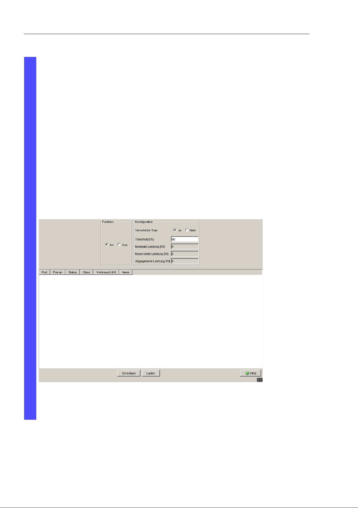
Configuring the Ports
The difference between the "nominal" and "reserved" power indicates
how much power is still available to the free PoE ports.
In the “POE on” column, you can enable/disable PoE at this port.
The “Status” column indicates the PoE status of the port.
In the “Priority” column (MACH 4000), set the PoE priority of the port
to “low”, “high” or “critical”.
The “Class” column shows the class of the connected device:
ClassMaximum power delivered
0: 15.4 W = state on delivery
1: 4.0 W
2: 7.0 W
3: 15,4 W
4: reserved, treat as class 0
The “Name” column indicates the name of the port, see
Basic settings:Port configuration.
Figure 20: Power over Ethernet dialog
76
Basic Configuration
Release 6.0 07/2010
Page 77

Protection from Unauthorized Access
6 Protection from Unauthorized
Access
The device provides you with the following functions to help you protect it
against unauthorized access.
X Password for SNMP access
X Telnet/Web/SSH access disabling
X Restricted management access
X HiDiscovery function disabling
X Port access control via IP or MAC address
X Port authentication according to IEEE 802.1X
Basic Configuration
Release 6.0 07/2010
77
Page 78

Protection from Unauthorized Access
6.1 Protecting the device
6.1 Protecting the device
If you want to maximize the protection of the device against unauthorized
access in just a few steps, you can perform some or all of the following steps
on the device:
Deactivate SNMPv1 and SNMPv2 and select a password for SNMPv3
access other than the standard password (see on page 80 “Entering the
password for SNMP access“).
Deactivate Telnet access.
Deactivate web access after you have downloaded the applet for the webbased interface onto your management station. You can start the webbased interface as an independent program and thus have SNMP access
to the device.
If necessary, deactivate SSH access (see on page 85 “Enabling/disabling
Telnet/Web/SSH Access“).
Deactivate HiDiscovery access.
Note: Make sure to retain at least one option to access the device. V.24
access is always possible, since it cannot be deactivated.
78
Basic Configuration
Release 6.0 07/2010
Page 79

Protection from Unauthorized Access
6.2 Password for SNMP access
6.2 Password for SNMP access
6.2.1 Description of password for SNMP access
A network management station communicates with the device via the Simple
Network Management Protocol (SNMP).
Every SNMP packet contains the IP address of the sending computer and the
password with which the sender of the packet wants to access the device
MIB.
The device receives the SNMP packet and compares the IP address of the
sending computer and the password with the entries in the device MIB.
If the password has the appropriate access right, and if the IP address of the
sending computer has been entered, then the device will allow access.
In the delivery state, the device is accessible via the password "public" (read
only) and "private" (read and write) to every computer.
To help protect your device from unwanted access:
First define a new password with which you can access from your
computer with all rights.
Treat this password as confidential, because everyone who knows the
password can access the device MIB with the IP address of your
computer.
Limit the access rights of the known passwords or delete their entries.
Basic Configuration
Release 6.0 07/2010
79
Page 80

Protection from Unauthorized Access
6.2 Password for SNMP access
6.2.2 Entering the password for SNMP access
Select the Security:Password/SNMP Access dialog.
This dialog gives you the option of changing the read and read/write
passwords for access to the device via the Web-based interface, via the
CLI, and via SNMPv3 (SNMP version 3). Please note that passwords
are case-sensitive.
Set different passwords for the read password and the read/write
password so that a user that only has read access (user name “user”)
does not know, or cannot guess, the password for read/write access
(user name “admin”).
If you set identical passwords, when you attempt to write this data the
device reports a general error.
The Web-based interface and the user interface (CLI) use the same
passwords as SNMPv3 for the users “admin” and “user”.
Select “Modify Read-Only Password (User)” to enter the read
password.
Enter the new read password in the “New Password” line and repeat
your entry in the “Please retype” line.
Select “Modify Read-Write Password (Admin)” to enter the read/
write password.
Enter the read/write password and repeat your entry.
"Data encryption" encrypts the data of the Web-based management
that is transferred between your PC and the device with SNMPv3.
You can set the "Data encryption" differently for access with a read
password and access with a read/write password.
80
Basic Configuration
Release 6.0 07/2010
Page 81

Protection from Unauthorized Access
6.2 Password for SNMP access
Figure 21: Password/SNMP Access dialog
Note: If you do not know a password with “read/write” access, you will
not have write access to the device.
Note: For security reasons, the device does not display the passwords.
Make a note of every change. You cannot access the device without a
valid password.
Note: For security reasons, SNMPv3 encrypts the password. With the
“SNMPv1” or “SNMPv2” setting in the dialog Security:SNMPv1/v2
access, the device transfers the password unencrypted, so that this
can also be read.
Note: Use between 5 and 32 characters for the password in SNMPv3,
since many applications do not accept shorter passwords.
Basic Configuration
Release 6.0 07/2010
81
Page 82

Protection from Unauthorized Access
6.2 Password for SNMP access
Select the Security:SNMPv1/v2 access dialog.
With this dialog you can select the access via SNMPv1 or SNMPv2.
In the state on delivery, both protocols are activated. You can thus
manage the device with HiVision and communicate with earlier
versions of SNMP.
If you select SNMPv1 or SNMPv2, you can specify in the table via which
IP addresses the device may be accessed, and what kinds of
passwords are to be used.
Up to 8 entries can be made in the table.
For security reasons, the read password and the read/write password
must not be identical.
Please note that passwords are case-sensitive.
Index Serial number for this table entry
Password Password with which this computer can access the
device. This password is independent of the SNMPv2
password.
IP address IP address of the computer that can access the device.
IP mask IP mask for the IP address
Access
mode
The access mode determines whether the computer has
read-only or read-write access.
Active Enable/disable this table entry.
82
Basic Configuration
Release 6.0 07/2010
Page 83

Protection from Unauthorized Access
6.2 Password for SNMP access
Figure 22: SNMPv1/v2 access dialog
To create a new line in the table click "Create entry".
To delete an entry, select the line in the table and click "Delete".
Basic Configuration
Release 6.0 07/2010
83
Page 84

Protection from Unauthorized Access
6.3 Telnet/Web/SSH Access
6.3 Telnet/Web/SSH Access
6.3.1 Description of Telnet Access
The Telnet server of the device allows you to configure the device by using
the Command Line Interface (in-band). You can deactivate the Telnet server
if you do not want Telnet access to the device.
On delivery, the server is activated.
After the Telnet server has been deactivated, you will no longer be able to
access the device via a new Telnet connection. If a Telnet connection already
exists, it is kept.
Note: The Command Line Interface (out-of-band) and the
Security:Telnet/Web access dialog in the Web-based interface allow
you to reactivate the Telnet server.
6.3.2 Description of Web Access
The Web server of the device allows you to configure the device by using the
Web-based interface. Deactivate the Web server if you do not want the
device to be accessed from the Web.
On delivery, the server is activated.
84
Basic Configuration
Release 6.0 07/2010
Page 85

Protection from Unauthorized Access
6.3 Telnet/Web/SSH Access
After the Web server has been switched off, it is no longer possible to log in
via a Web browser. The login in the open browser window remains active.
6.3.3 Description of SSH Access
The SSH server of the device allows you to configure the device by using the
Command Line Interface (in-band). You can deactivate the SSH server to
disable SSH access to the device.
On delivery, the server is deactivated.
After the SSH server has been deactivated, you will no longer be able to
access the device via a new SSH connection. If an SSH connection already
exists, it is kept.
Note: The Command Line Interface (out-of-band) and the
Security:Telnet/Web access dialog in the Web-based interface allow
you to reactivate the SSH server.
Note: To be able to access the device via SSH, you need a key that has to
be installed on the device (see the "Basic Configuration" user manual).
6.3.4 Enabling/disabling Telnet/Web/SSH Access
Select the Security:Telnet/Web/SHH access dialog.
Disable the server to which you want to refuse access.
Basic Configuration
Release 6.0 07/2010
85
Page 86

Protection from Unauthorized Access
enable Switch to the Privileged EXEC mode.
configure Switch to the Configuration mode.
lineconfig Switch to the configuration mode for CLI.
transport input telnet Enable Telnet server.
no transport input telnet Disable Telnet server.
exit Switch to the Configuration mode.
ip http server Enable Web server.
no ip http server Disable Web server.
ip ssh Enable SSH function on Switch
no ip ssh Disable SSH function on Switch
6.3 Telnet/Web/SSH Access
86
Basic Configuration
Release 6.0 07/2010
Page 87

Protection from Unauthorized Access
6.4 Restricted Management Access
6.4 Restricted Management
Access
The device allows you to differentiate the management access to the device
based on IP address ranges, and to differentiate these based on
management services (http, snmp, telnet, ssh). You thus have the option to
set finely differentiated management access rights.
If you only want the device, which is located, for example, in a production
plant, to be managed from the network of the IT department via the Web
interface, but also want the administrator to be able to access it remotely via
SSH, you can achieve this with the “Restricted management access”
function.
You can configure this function using the Web-based interface or the CLI.
The Web-based interface provides you with an easy configuration option.
Make sure you do not unintentionally block your access to the device. The
CLI access to the device via V.24 provided at all times is excluded from the
function and cannot be restricted.
In the following example, the IT network has the address range 192.168.1.0/
24 and the remote access is from a mobile phone network with the IP
address range 109.237.176.0 - 109.237.176.255.
The device is always ready for the SSH access (see on page 233 “Preparing
Access via SSH“) and the SSH client application already knows the
fingerprint of the host key on the device.
Parameter Value
IT network address 192.168.1.0
IT network netmask 255.255.255.0
Desired management access from the IT network http, snmp
Mobile phone network address 109.237.176.0
Mobile phone network netmask 255.255.255.0
Desired management access from the mobile phone
network
ssh
Table 4: Example parameter for the restricted management access
Basic Configuration
Release 6.0 07/2010
87
Page 88

Protection from Unauthorized Access886.4 Restricted Management Access
enable Switch to the Privileged EXEC mode.
show network mgmt-access Display the current configuration.
network mgmt-access add Create an entry for the IT network. This is given
the smallest free ID - in the example, 2.
network mgmt-access modify 2
ip 192.168.1.0
network mgmt-access modify 2
netmask 255.255.255.0
network mgmt-access modify 2
telnet disable
network mgmt-access modify 2
ssh disable
network mgmt-access add Create an entry for the mobile phone network. In
network mgmt-access modify 3
ip 109.237.176.0
network mgmt-access modify 3
netmask 255.255.255.0
network mgmt-access modify 3
http disable
network mgmt-access modify 3
snmp disable
network mgmt-access modify 3
telnet disable
network mgmt-access status 1
disable
network mgmt-access
operation enable
show network mgmt-access Display the current configuration of the function.
copy system:running-config
nvram:startup-config
Set the IP address of the entry for the IT network.
Set the netmask of the entry for the IT network.
Deactivate telnet for the entry of the IT network.
Deactivate SSH for the entry of the IT network.
the example, this is given the ID 3.
Set the IP address of the entry for the mobile
phone network.
Set the netmask of the entry for the mobile phone
network.
Deactivate http for the entry of the mobile phone
network.
Deactivate snmp for the entry of the mobile phone
network.
Deactivate telnet for the entry of the mobile phone
network.
Deactivate the preset entry.
Activates the function immediately.
Save the entire configuration in the non-volatile
memory.
Basic Configuration
Release 6.0 07/2010
Page 89

Protection from Unauthorized Access
6.5 HiDiscovery Access
6.5 HiDiscovery Access
6.5.1 Description of the HiDiscovery Protocol
The HiDiscovery protocol allows you to allocate an IP address to the device
on the basis of its MAC address (see on page 36 “Entering the IP Parameters
via HiDiscovery“). HiDiscovery is a Layer 2 protocol.
Note: For security reasons, restrict the HiDiscovery function for the device or
disable it after you have assigned the IP parameters to the device.
6.5.2 Enabling/disabling the HiDiscovery Function
Select the Basics:Network dialog.
Disable the HiDiscovery function in the "HiDiscovery Protocol" frame
or limit the access to "read-only".
enable Switch to the Privileged EXEC mode.
network protocol hidiscovery
off
network protocol hidiscovery
read-only
network protocol hidiscovery
read-write
Disable HiDiscovery function.
Enable HiDiscovery function with "read-only"
access
Enable HiDiscovery function with "read-write"
access
d
Basic Configuration
Release 6.0 07/2010
89
Page 90

Protection from Unauthorized Access
6.5 HiDiscovery Access
6.5.3 Description of the Port Access Control
You can configure the device in such a way that it helps to protect every port
from unauthorized access. Depending on your selection, the device checks
the MAC address or the IP address of the connected device.
The following functions are available for monitoring every individual port:
X The device can distinguish between authorized and unauthorized access
and supports two types of access control:
X Access for all:
– no access restriction.
– MAC address 00:00:00:00:00:00 or
– IP address 0.0.0.0.
X Access exclusively for defined MAC and IP addresses:
– only devices with defined MAC or IP addresses have access.
– You can define up to 10 IP addresses, MAC addresses or maskable
MAC addresses.
X The device can react to an unauthorized access attempt in 3 selectable
ways:
X none: no response
X trapOnly: message by sending a trap
X portDisable: message by sending a trap and disabling the port
6.5.4 Application Example for Port Access Control
You have a LAN connection in a room that is accessible to everyone. To set
the device so that only defined users can use the LAN connection, activate
the port access control on this port. An unauthorized access attempt will
cause the device to shut down the port and alert you with an alarm message.
The following is known:
90
Basic Configuration
Release 6.0 07/2010
Page 91

Protection from Unauthorized Access
Parameter Value Explanation
Allowed IP Addresses 10.0.1.228
10.0.1.229
Action portDisable Disable the port with the corresponding entry in the
The defined users are the device with the
IP address 10.0.1.228 and the device with the
IP address 10.0.1.229
port configuration table (see on page 73
“Configuring the Ports“) and send an alarm
6.5 HiDiscovery Access
Prerequisities for further configuration:
X The port for the LAN connection is enabled and configured correctly (see
on page 73 “Configuring the Ports“)
X Prerequisites for the device to be able to send an alarm (trap) (see on
page 179 “Configuring Traps“):
– You have entered at least one recipient
– You have set the flag in the “Active” column for at least one recipient
– In the “Selection” frame, you have selected “Port Security”
Basic Configuration
Release 6.0 07/2010
91
Page 92

Protection from Unauthorized Access
Configure the port security.
6.5 HiDiscovery Access
Select the Security:Port Security dialog.
In the “Configuration” frame, select “IP-Based Port Security”.
In the table, click on the row of the port to be protected, in the
“Allowed IP addresses” cell.
Enter in sequence:
– the IP subnetwork group: 10.0.1.228
– a space character as a separator
– the IP address: 10.0.1.229
Entry:
10.0.1.228 10.0.1.229
In the table, click on the row of the port to be protected, in the
“Action” cell, and select portDisable.
Figure 23: Port Security dialog
92
Basic Configuration
Release 6.0 07/2010
Page 93

Protection from Unauthorized Access
6.5 HiDiscovery Access
Save the settings in the non-volatile memory.
Select the dialog Basic Settings:Load/Save.
In the “Save” frame, select “To Device” for the location and click
“Save” to permanently save the configuration in the active
configuration.
Basic Configuration
Release 6.0 07/2010
93
Page 94

Protection from Unauthorized Access946.6 Port Authentication IEEE 802.1X
802.1X SupplicantSwitch/AuthenticatorRADIUS Server
6.6 Port Authentication IEEE 802.1X
6.6.1 Description of Port Authentication according to IEEE 802.1X
The port-based network access control is a method described in the standard
IEEE 802.1X to protect IEEE 802 networks from unauthorized access. The
protocol controls the access to a port by authenticating and authorizing a
device that is connected to this port of the device.
The authentication and authorization is performed by the authenticator, in
this case the device. The device authenticates (or does not authenticate) the
supplicant (the querying device, e.g. a PC), which means that it permits the
access to the services it provides (e.g. access to the network to which the
device is connected), or else refuses it. In the process, the device accesses
an external authentication server (RADIUS server), which checks the
authentication data of the supplicant. The device exchanges the
authentication data with the supplicant via the Extensible Authentication
Protocol over LANs (EAPOL), and with the RADIUS server via the RADIUS
protocol.
Figure 24: Radius server connection
Basic Configuration
Release 6.0 07/2010
Page 95

Protection from Unauthorized Access
6.6 Port Authentication IEEE 802.1X
6.6.2 Authentication Process according to IEEE 802.1X
A supplicant attempts to communicate via a device port.
X The device requests authentication from the supplicant. At this time, only
EAPOL traffic is allowed between the supplicant and the device.
X The supplicant replies with its identification data.
X The device forwards the identification data to the authentication server.
X The authentication server responds to the request in accordance with the
access rights.
X The device evaluates this response and provides the supplicant with
access to this port (or leaves the port in the blocked state).
6.6.3 Preparing the Device for the IEEE 802.1X Port Authentication
Configure your own IP parameters (for the device).
Globally enable the 802.1X port authentication function.
Set the 802.1X port control to "auto". The default setting is "force-
authorized".
Enter the "shared secret" between the authenticator and the Radius
server. The shared secret is a text string specified by the RADIUS server
administrator.
Enter the IP address and the port of the RADIUS server. The default UDP
port of the RADIUS server is port 1812.
Basic Configuration
Release 6.0 07/2010
95
Page 96

Protection from Unauthorized Access966.6 Port Authentication IEEE 802.1X
6.6.4 IEEE 802.1X Settings
Configurating the RADIUS Server
Select the Security:802.1x Port Authentication:RADIUS
Server dialog.
This dialog allows you to enter the data for 1, 2 or 3 RADIUS servers.
Click "Create entry" to open the dialog window for entering the IP
address of a RADIUS server.
Confirm the IP address entered using "OK".
You thus create a new row in the table for this RADIUS server.
In the "Shared secret" column you enter the character string which
you get as a key from the administrator of your RADIUS server.
With "Primary server" you name this server as the first server which
the device should contact for port authentication queries. If this
server is not available, the device contacts the next server in the
table.
"Selected server" shows which server the device actually sends its
queries to.
With "Delete entry" you delete the selected row in the table.
Selecting Ports
Select the Security:802.1x Port Authentication:Port
Configuration dialog.
In the "Port control" column you select "auto" for the ports for which
you want to activate the port-related network access control.
Activating Access Control
Select the Security:802.1x Port
Authentication:Global dialog.
With "Function" you enable the function.
Basic Configuration
Release 6.0 07/2010
Page 97

Synchronizing the System Time in the Network
7 Synchronizing the System
Time in the Network
The actual meaning of the term “real time” depends on the time requirements
of the application.
The device provides two options with different levels of accuracy for
synchronizing the time in your network.
If you only require an accuracy in the order of milliseconds, the Simple
Network Time Protocol (SNTP) provides a low-cost solution. The accuracy
depends on the signal runtime.
IEEE 1588 with the Precision Time Protocol (PTP) achieves accuracies in
the order of fractions of microseconds. This superior method is suitable for
process control, for example.
Examples of application areas include:
X log entries
X time stamping of production data
X production control, etc.
Select the method (SNMP or PTP) that best suits your requirements. You can
also use both methods simultaneously if you consider that they interact.
Basic Configuration
Release 6.0 07/2010
97
Page 98

Synchronizing the System Time in the
Network
7.1 Entering the Time
7.1 Entering the Time
If no reference clock is available, you have the option of entering the system
time in a device and then using it like a reference clock (see on page 102
“Configuring SNTP“), (see on page 112 “Application Example“).
Note: When setting the time in zones with summer and winter times, make
an adjustment for the local offset. The device can also get the SNTP server
IP address and the local offset from a DHCP server.
Select the Time dialog.
With this dialog you can enter time-related settings independently of the
time synchronization protocol selected.
X The “IEEE 1588 time” displays the time determined using PTP.
The “SNTP time” displays the time with reference to Universal Time
Coordinated (UTC).
The display is the same worldwide. Local time differences are not
taken into account.
X The “System time” uses the “IEEE 1588 / SNTP time”, allowing for
the local time difference from “IEEE 1588 / SNTP time”.
“System time” = “IEEE 1588 / SNTP time” + “Local offset”.
X “Time source” displays the source of the following time data. The
device automatically selects the source with the greatest accuracy.
Possible sources are: local and sntp. The source is initially
local. If SNTP is activated and if the device receives a valid SNTP
packet, the device sets its time source to sntp.
98
Basic Configuration
Release 6.0 07/2010
Page 99

Synchronizing the System Time in the
7.1 Entering the Time
Network
With “Set time from PC”, the device takes the PC time as the system
time and calculates the IEEE 1588 / SNTP time using the local time
difference.
“IEEE 1588 / SNTP time” = “System time” - “Local offset”
The “Local Offset” is for displaying/entering the time difference
between the local time and the “IEEE 1588 / SNTP time”.
With “Set offset from PC”, the agent determines the time zone on
your PC and uses it to calculate the local time difference.
enable Switch to the Privileged EXEC mode.
configure Switch to the Configuration mode.
sntp time <YYYY-MM-DD
HH:MM:SS>
sntp client offset <-1000 to
1000>
Set the system time of the device.
Enter the time difference between the local time
and the "IEEE 1588 / SNTP time".
Basic Configuration
Release 6.0 07/2010
99
Page 100

Synchronizing the System Time in the
GPS
NTPServer
ServerClient
Client
Client
Switch
PLC
ServerClient
Switch
ServerClient
Switch
192.168.1.1 192.168.1.2 192.168.1.3
192.168.1.0
7.2 SNTP
Network
7.2 SNTP
7.2.1 Description of SNTP
The Simple Network Time Protocol (SNTP) enables you to synchronize the
system time in your network.
The device supports the SNTP client and the SNTP server function.
The SNTP server makes the UTC (Universal Time Coordinated) available.
UTC is the time relating to the coordinated world time measurement. The
time displayed is the same worldwide. Local time differences are not taken
into account.
The SNTP client obtains the UTC from the SNTP server.
Figure 25: SNTP cascade
100
Basic Configuration
Release 6.0 07/2010
 Loading...