

Hirschmann RSPM20-4Z64Z6, RSPM22-4T14T1, RSPM20-4T14T1, RSPM20-4T14Z6, RSPM22-4T14Z6 User Manual
Installation RSPM
Release 15 04/2018
Technical support
https://hirschmann-support.belden.eu.com
User Manual
Installation
Industrial Ethernet Rail Switch Power Media module
RSPM

The naming of copyrighted trademarks in this manual, even when not specially indicated, should
not be taken to mean that these names may be considered as free in the sense of the trademark
and tradename protection law and hence that they may be freely used by anyone.
© 2018 Hirschmann Automation and Control GmbH
Manuals and software are protected by copyright. All rights reserved. The copying, reproduction,
translation, conversion into any electronic medium or machine scannable form is not permitted,
either in whole or in part. An exception is the preparation of a backup copy of the software for
your own use.
The performance features described here are binding only if they have been expressly agreed
when the contract was made. This document was produced by Hirschmann Automation and
Control GmbH according to the best of the company's knowledge. Hirschmann reserves the right
to change the contents of this document without prior notice. Hirschmann can give no guarantee
in respect of the correctness or accuracy of the information in this document.
Hirschmann can accept no responsibility for damages, resulting from the use of the network
components or the associated operating software. In addition, we refer to the conditions of use
specified in the license contract.
You can get the latest version of this manual on the Internet at the Hirschmann product site
(www.hirschmann.com).
Hirschmann Automation and Control GmbH
Stuttgarter Str. 45-51
72654 Neckartenzlingen
Germany
RSPM 26.04.2018

Installation RSPM
Release 15 04/2018
3
Contents
Safety instructions 5
About this manual 14
Key 15
1 Description 16
1.1 General description 16
1.2 Device name and product code 17
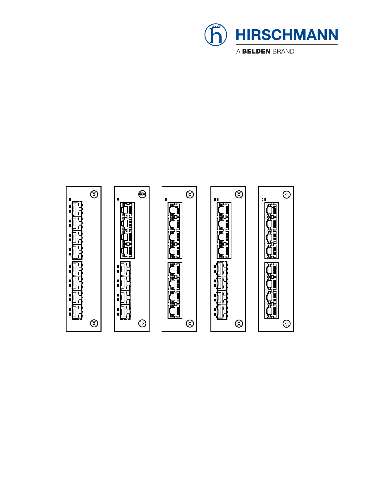
1.3 Media module variants 19
1.3.1 Port configuration 19
1.3.2 Media module slots on the RSPE device 20
1.4 Ethernet ports 21
1.4.1 100 Mbit/s F/O port 21
1.4.2 10/100 Mbit/s twisted pair port 21
1.4.3 Support of PoE(+) 22
1.5 Display elements 23
1.5.1 Media module status 23
1.5.2 Port status 24
2 Installation 25
2.1 Checking the package contents 25
2.2 Mounting a media module 25
2.3 Installing an SFP transceiver (optional) 26
2.4 Connecting data cables 26
3 Maintenance and service 27
4 Disassembly 28
4.1 Removing an SFP transceiver (optional) 28
4.2 Removing a media module 28
5 Technical data 29
6 Scope of delivery, order numbers and
accessories 35

4
Installation RSPM
Release 15 04/2018
6.1 Scope of delivery 35
6.2 Accessories 35
7 Underlying technical standards 37
A Further support 38

Installation RSPM
Release 15 04/2018
5
Safety instructions
General safety instructions
You operate this device with electricity. Improper usage of the device
entails the risk of physical injury or significant property damage. The
proper and safe operation of this device depends on proper handling
during transportation, proper storage and installation, and careful
operation and maintenance procedures.
Before connecting any cable, read this document, and the safety
instructions and warnings.
Operate the device with undamaged components exclusively.
The device is free of any service components. In case of a damaged
or malfunctioning the device, turn off the supply voltage and return the
device to Hirschmann for inspection.
Certified usage
Use the product only for the application cases described in the
Hirschmann product information, including this manual.
Operate the product only according to the technical specifications.
See “Technical data” on page 29.
Connect to the product only components suitable for the requirements
of the specific application case.
Qualification requirements for personnel
Only allow qualified personnel to work on the device.
Qualified personnel have the following characteristics:
Qualified personnel are properly trained. Training as well as practical
knowledge and experience make up their qualifications. This is the
prerequisite for grounding and labeling circuits, devices, and systems
in accordance with current standards in safety technology.
Qualified personnel are aware of the dangers that exist in their work.
Qualified personnel are familiar with appropriate measures against
these hazards in order to reduce the risk for themselves and others.
Qualified personnel receive training on a regular basis.
National and international safety regulations
Verify that the electrical installation meets local or nationally applicable
safety regulations.

6
Installation RSPM
Release 15 04/2018
Shielding ground
The overall shield of a connected shielded twisted pair cable is connected
to the grounding connector on the front panel as a conductor.
Beware of possible short circuits when connecting a cable section with
conductive shielding braiding.
ESD Guidelines
The modules are equipped with electrostatically sensitive components.
These can be destroyed, or their life cycles reduced, by the effects of an
electrical field or by a charge equalization if the connections are touched.
You will find information about electrostatically endangered assemblies in
DIN EN 61340-5-1 (2007-08) and DIN EN 61340-5-2 (2007-08).

Installation RSPM
Release 15 04/2018
7
ATEX directive 2014/34/EU – specific regulations for safe
operation
The following applies to RSPM devices if you operate them in areas with
explosive gases according to ATEX directive 2014/34/EU:
List of standards:
EN 60079-0:2012, A11:2013
EN 60079-15:2010
Certificate No.: DEKRA 15ATEX0016X
Use only device variants featuring supply voltage with characteristic
value CC.
Make sure that the device has the following label:
II 3G Ex nA IIC T4 Gc DEKRA 15ATEX0016X
for RSPM types
Environmental class and temperature code for RSPM types:
T4: 0 °C ≤ Ta ≤ +60 °C for “S“ types or
T4: −40 °C ≤ Ta ≤ +70 °C for “T“ or “E“ types
Ambient rating and temperature code for RSPM types:
T4: 0 °C ≤ Ta ≤ +60 °C for “S” types or
T4: −40 °C ≤ Ta ≤ +70 °C for “T” or “E” types
The modules shall be installed in a suitable enclosure in accordance
with IEC 60079-15 providing a degree of protection of at least IP54
according to IEC 60529, taking into account the environmental
conditions under which the equipment will be used.
When the temperature under rated conditions exceeds 158 °F (70 °C)
at the cable or conduit entry point, or 176 °F (80 °C) at the branching
point of the conductors, the temperature specification of the selected
cable and cable entries shall be in compliance with the actual
measured temperature values.
Provisions shall be made to prevent the rated voltage from being
exceeded by transient disturbances of more than 119 V.
Connectors shall be connected or disconnected exclusively in dead-
voltage state.
The USB port must not be connected.

8
Installation RSPM
Release 15 04/2018
Relevant for use in explosion hazard areas (Hazardous
Locations, Class I, Division 2)
The relay connections are to be installed and used within their Entity
Parameters as per Control Drawing 000182303DNR.
Avertissement - Risque d'explosion - Ne pas débrancher tant que le
circuit est sous tension à moins que l'emplacement soit connu pour ne
contenir aucune concentration de gaz inflammable.
Avertissement - Risque d'explosion - La substitution de tout composant
peut rendre ce matériel incompatible pour une utilisation en classe I,
division 2.

Installation RSPM
Release 15 04/2018
9
Control Drawing for RSPE devices according to Class , Division 2 Hazardous Locations
Rev.: 1 Document No.: 000182303DNR Page 1/2
For Use in Hazardous Locations Class I Division 2 Groups A, B, C, D:
Only allowed for RSPE/RSPM model No´s. which are individually labeled
“FOR USE IN HAZARDOUS LOCATIONS”.
This equipment is suitable for use in Class I, Division 2,
Groups A, B, C, and D OR non-hazardous locations only.
Nonincendive eld wiring circuits must be wired in accordance with the National Electrical Code
(NEC), NFPA 70, article 501.
WARNING – EXPLOSION HAZARD
Substitution of any components may impair suitability for hazardous locations or explosive
atmospheres.
WARNING – EXPLOSION HAZARD
Do not disconnect equipment unless power has been switched off or the area is known to be
known to be non-hazardous.
10
Installation RSPM
Release 15 04/2018
Control Drawing for RSPE devices according to Class , Division 2 Hazardous Locations
Rev.: 1 Document No.: 000182303DNR Page 2/2
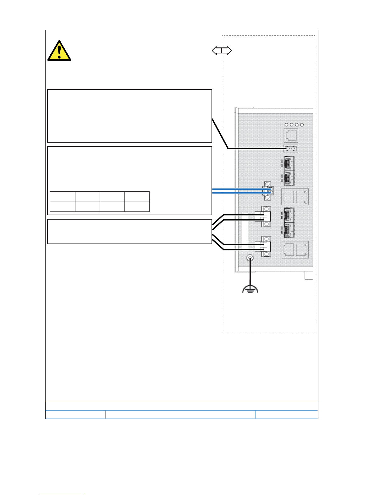
Ordinary Location,
Non-Hazardous Area,
Non-Explosive Atmosphere
Explosive Atmosphere
Class , Division 2
Groups A, B, C, D
Hazardous Location
RSPE - Industrial Ethernet
Rail Switch Power Enhanced
Relay
USB
P1
P2
The earth conductor must
be at least of the same
wire size (mm² or
AWG)
as the supply conductors.
Temperature Code: T4
Ambient Temperature rating:
Ta: 0 °C to +60 °C for “S” temperature types
Ta: í40 °C to +70 °C for “T” or “E” temperature types
(Refer to the temperature code of the type designation on the
device.)
Power Supply connectors
*) Notes:
The nonincendive eld wiring circuit concept allows interconnection
of nonincendive eld wiring apparatus and associated nonincendive
eld wiring apparatus using any of the wiring methods permitted for
unclassi ed locations when certain parametric conditions are met.
Capacity: Ca Ci + C
Cable
; Inductivity: La Li + L
Cable
WARNING!
The USB is for temporary connection only, for maintenance
use. Do not use, connect or disconnect unless the area is
known to be non-hazardous.
Connection or disconnection in an explosive atmosphere
could result in an explosion.
The maximum cable length has to be determined as follows:
(a) max. Cable Length < (La í Li) / Cable
L
(”CableL” denotes the inductance per unit length of used cable)
and
(b) max. Cable Length < (Ca í Ci) / Cable
C
(“CableC” denotes the capacitance per unit length of used cable)
The lower value of (a) and (b) is to apply.
Relay contacts:
Equipment with nonincendive eld wiring parameters.
Polarity is not relevant.
The relay terminals are dependent upon the following
Entity parameters:
U
i
I
i
C
i
L
i
30 V 90 mA 2 nF 1 H
Installation RSPM
Release 15 04/2018
11
IECEx – Certification Scheme for Explosive Atmospheres
For RSPM devices labeled with an IECEx certificate number, the following
applies:
List of standards:
IEC 60079-0:2011+Cor.2012+Cor.2013
IEC 60079-15:2010
The device is suitable for use in an area with a degree of soiling of 2
as per IEC 60664-1.
Make sure that the device has the following label:
Ex nA IIC T4 Gc IECEx DEK 15.0013X
for RSPM types
Environmental class and temperature code for RSPM types:
T4: 0 °C ≤ Ta ≤ +60 °C for “S“ types or
T4: −40 °C ≤ Ta ≤ +70 °C for “T“ or “E“ types
The modules shall be installed in a suitable enclosure in accordance
with IEC 60079-15 providing a degree of protection of at least IP54
according to IEC 60529, taking into account the environmental
conditions under which the equipment will be used.
When the temperature under rated conditions exceeds 70 °C at the
cable or conduit entry point, or 80 °C at the branching point of the
conductors, the temperature specification of the selected cable and
cable entries shall be in compliance with the actual measured
temperature values.
Provisions shall be made to prevent the rated voltage from being
exceeded by transient disturbances of more than 119 V.
Connectors shall be connected or disconnected exclusively in dead-
voltage state.
The USB port shall remain disconnected.

12
Installation RSPM
Release 15 04/2018
CE marking
The statements in this chapter refer only to media modules which are
correctly mounted in a RSPE basic device (see on page 25 “Mounting a
media module”).
The labeled devices comply with the regulations contained in the following
European directive(s):
2011/65/EU (RoHS)
Directive of the European Parliament and of the Council on the restriction
of the use of certain hazardous substances in electrical and electronic
equipment.
2014/30/EU (EMC)
Directive of the European Parliament and the council for standardizing the
regulations of member states with regard to electromagnetic
compatibility.
In accordance with the above-named EU directive(s), the EU conformity
declaration will be at the disposal of the relevant authorities at the
following address:
Hirschmann Automation and Control GmbH
Stuttgarter Str. 45-51
72654 Neckartenzlingen
www.hirschmann.com
The device can be used in the industrial sector.
Interference immunity: EN 61000-6-2
Emitted interference: EN 55032
Reliability: EN 60950-1
You find more information on technical standards here:
“Technical data” on page 29
Warning! This is a class A device. This device can cause interference in
living areas, and in this case the operator may be required to take
appropriate measures.
LED or laser components
LED or LASER components according to IEC 60825-1 (2014):
CLASS 1 LASER PRODUCT
CLASS 1 LED PRODUCT
 Loading...