

Hirschmann RSPL 20, RSPL30 User Manual
Installation RSPL 20/30
Release 04 02/2013
Technical support
https://hirschmann-support.belden.eu.com
User Manual
Installation
Industrial Ethernet Rail Switch Power Lite
RSPL 20/30

The naming of copyrighted trademarks in this manual, even when not specially indicated, should
not be taken to mean that these names may be considered as free in the sense of the trademark
and tradename protection law and hence that they may be freely used by anyone.
© 2013 Hirschmann Automation and Control GmbH
Manuals and software are protected by copyright. All rights reserved. The copying, reproduction,
translation, conversion into any electronic medium or machine scannable form is not permitted,
either in whole or in part. An exception is the preparation of a backup copy of the software for
your own use. For devices with embedded software, the end-user license agreement on the
enclosed CD/DVD applies.
The performance features described here are binding only if they have been expressly agreed
when the contract was made. This document was produced by Hirschmann Automation and
Control GmbH according to the best of the company's knowledge. Hirschmann reserves the right
to change the contents of this document without prior notice. Hirschmann can give no guarantee
in respect of the correctness or accuracy of the information in this document.
Hirschmann can accept no responsibility for damages, resulting from the use of the network
components or the associated operating software. In addition, we refer to the conditions of use
specified in the license contract.
You can get the latest version of this manual on the Internet at the Hirschmann product site
(www.hirschmann.com).
Printed in Germany
Hirschmann Automation and Control GmbH
Stuttgarter Str. 45-51
72654 Neckartenzlingen
Germany
Tel.: +49 1805 141538
Installation RSPL 20/30 040 016-001-04-0213 - 19.02.2013

Installation RSPL 20/30
Release 04 02/2013
3
Contents
Safety instructions 5
About this manual 12
Key 12
1 Device description 13
1.1 General device description 13
1.2 Device name and product code 14
1.3 Combination options 17
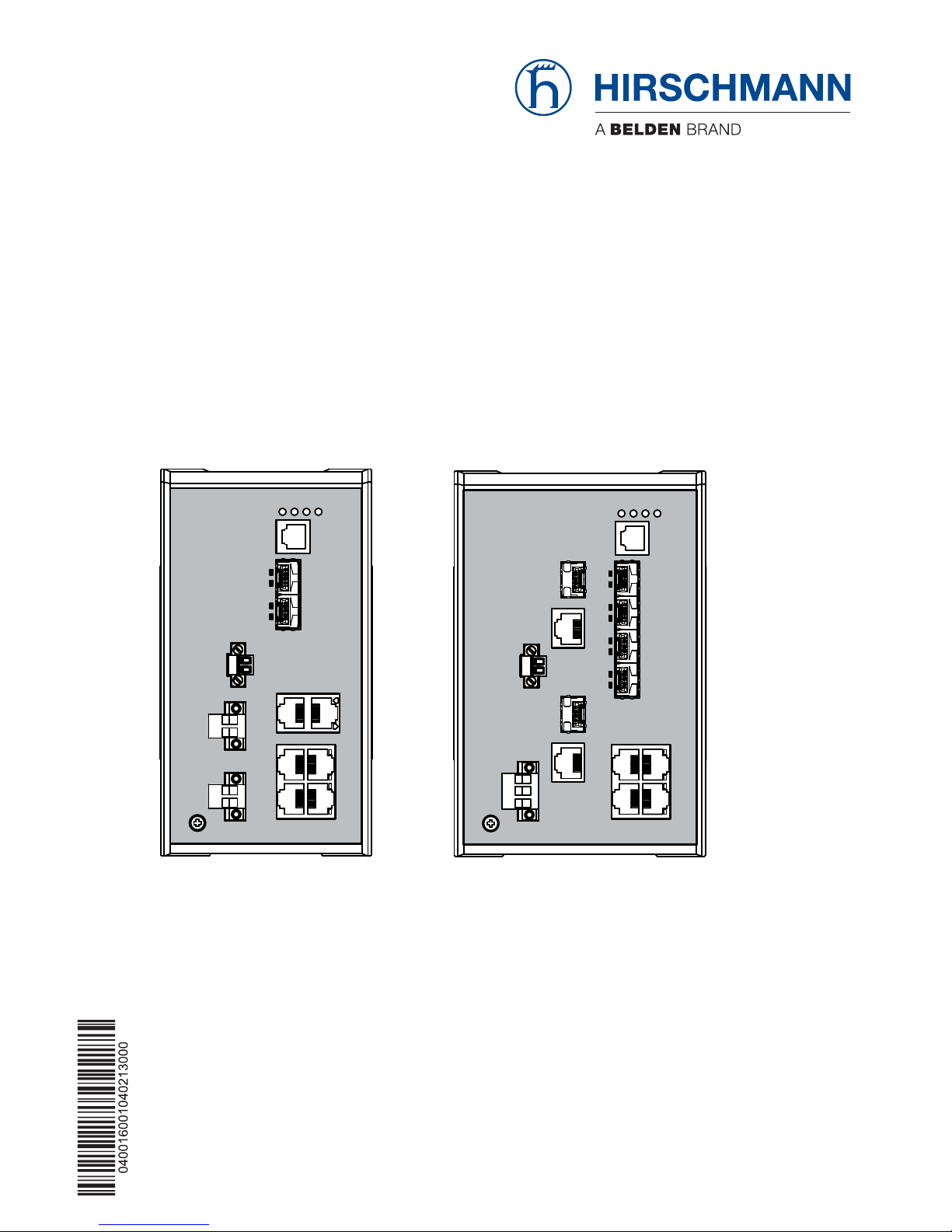
1.4 Device views 18
1.4.1 Front view 18
1.4.2 Rear view 20
1.5 Power supply 20
1.5.1 Operating voltage type M9 20
1.5.2 Operating voltage type CC 20
1.6 Ethernet ports 21
1.6.1 Gigabit combo port (optional) 21
1.6.2 10/100 Mbit/s twisted pair connection 22
1.6.3 100 Mbit/s F/O connection 22
1.7 Display elements 23
1.7.1 Device state 23
1.7.2 Port state 24
1.8 Management interfaces 24
1.8.1 V.24 interface (external management) 24
1.8.2 SD card interface 25
1.9 Signal contact 26
2 Device installation 27
2.1 Unpacking and checking 27
2.2 Installing the SD card (optional) 27
2.3 Installing the device and grounding 28
2.3.1 Mounting on the DIN rail 28
2.3.2 Grounding 29
2.4 Installing the SFP transceivers (optional) 29
2.5 Connecting the terminal blocks 30

4
Installation RSPL 20/30
Release 04 02/2013
2.6 Mounting the terminal blocks and switching on the supply
voltage 33
2.7 Connecting the data lines 33
2.7.1 Gigabit combo port (optional) 33
2.7.2 100 Mbit/s F/O connection 34
2.7.3 10/100 Mbit/s twisted pair connection 34
2.8 Insert data in label area 34
3 Basic set-up 35
4 Monitoring the ambient air temperature 36
5 Maintenance and service 37
6Disassembly 38
6.1 Disassembling the device 38
6.2 Removing the SFP transceivers 39
7 Technical data 40
A Further Support 52
Installation RSPL 20/30
Release 04 02/2013
5
Safety instructions
Certified usage
Only use the device for application cases that are described in the
Hirschmann product information, including this manual. Only operate the
device according to the technical specifications.
Supply voltage
Note: The supply voltage is only connected with the chassis via protective
elements.
Only for device variants with operating voltage type M9:
For the supply voltage to be connected, make sure the following
requirements are met:
The power supply conforms to overvoltage category I or II.
The voltage supply has an easily accessible disconnecting device
(e.g. a switch or a plug). This disconnecting device is clearly
identified so that in the case of an emergency, it is clear which
disconnecting device belongs to which line.
The lines to be connected are voltage-free.
Supply with DC voltage:
A fuse suitable for DC voltage is located in the plus conductor of the
power supply. A fuse is also located in the minus conductor, if this
is not grounded.
Regarding the properties of this fuse: See “General technical data”
on page 40.
Supply with AC voltage:
A fuse is located in the outer conductor of the power supply. A fuse
is also located in the neutral conductor, if this is not grounded.
Regarding the properties of this fuse: See “General technical data”
on page 40.
AC voltage Supply: the wire diameter for the input supply line is at
least 0.75 mm² (North America: AWG18).
DC voltage Supply: the wire diameter for the input supply line is at
least 1 mm² (North America: AWG16).
WARNING
ELECTRIC SHOCK
Ground the device before connecting the power supply.
Only connect a supply voltage as described in the data plate of your device.
Failure to follow these instructions can result in death, serious injury,
or equipment damage.
6
Installation RSPL 20/30
Release 04 02/2013
The cross-section of the protective conductor cable is the same
size as or bigger than the cross-section of the voltage supply
cables.
The connection cables used are permitted for the specified
temperature range.
Relevant for North America:
The power supply lines are made up of copper wire (75 °C).
Only for device variants with operating voltage type CC:
For every supply voltage to be connected, make sure the following
requirements are met:
The power supply corresponds to Class 2.
The power supply conforms to overvoltage category I or II.
The voltage supply has an easily accessible disconnecting device
(e.g. a switch or a plug). This disconnecting device is clearly
identified so that in the case of an emergency, it is clear which
disconnecting device belongs to which line.
The lines to be connected are voltage-free.
A fuse suitable for DC voltage is located in the plus conductor of the
power supply. A fuse is also located in the minus conductor, if this
is not grounded.
Regarding the properties of this fuse: See “General technical data”
on page 40.
The wire diameter for the input supply line is at least 1 mm² (North
America: AWG16).
The connection cables used are permitted for the specified
temperature range.
Relevant for North America:
The power supply lines are made up of copper wire (75 °C).
WARNING
ELECTRIC SHOCK
Only start connecting the supply voltage if all the above mentioned
requirements are fulfilled.
Failure to follow these instructions can result in death, serious injury,
or equipment damage.

Installation RSPL 20/30
Release 04 02/2013
7
Make sure that the electrical installation meets local or nationally
applicable safety regulations.
Use undamaged parts.
The device does not contain any service components. Internal fuses
are only triggered if there is a fault in the device. If the device is not
functioning correctly, or if it is damaged, switch off the voltage supply
and return the device to the plant for inspection.
Connect the protective conductor with the ground screw before you
set up the other connections. When removing the connections, you
remove the protective conductor last.
For supply voltages with protective conductor connections: first
connect the protective conductor before connecting the lines for the
supply voltages.
Only switch on the supply voltage for the device when the following
prerequisites are fulfilled:
The housing is closed
The terminal blocks are wired correctly
The terminal blocks for the voltage supply are connected
Shielded ground
The shielded ground wire of the twisted pairs lines is connected to the
front panel as a conductor.
Beware of possible short circuits when connecting a cable section with
conductive shield braiding.
8
Installation RSPL 20/30
Release 04 02/2013
Housing
Only technicians authorized by the manufacturer are permitted to open
the housing.
WARNING
ELECTRIC SHOCK
Never insert sharp objects (small screwdrivers, wires, etc.) into the inside of
the device.
Never insert sharp objects (small screwdrivers, wires, etc.) into the
connection terminals for the supply voltage or the signal contact, and do not
touch the terminals!
Failure to follow these instructions can result in death, serious injury,
or equipment damage.
WARNING
FIRE HAZARD
Install the device in a fire protected enclosure according to EN 60950-1.
Failure to follow these instructions can result in death, serious injury,
or equipment damage.
WARNING
Only for device variants with operating voltage type M9:
ELECTRIC SHOCK
Only install this device in a switch cabinet or in an operating site with limited
access, to which only maintenance staff have access.
Failure to follow these instructions can result in death, serious injury,
or equipment damage.

Installation RSPL 20/30
Release 04 02/2013
9
The device is grounded by the separate ground screw on the front panel.
Make sure that the electrical installation meets local or nationally
applicable safety regulations.
Keep the ventilation slits free to ensure good air circulation.
Make sure there is at least 10 cm of space in front of the ventilation
slits of the housing.
Install the device in the vertical position.
Environment
Operate the device at the specified surrounding air temperature
(temperature of the surrounding air at a distance of up to 1.97 in (5 cm)
from the device) and relative air humidity specified in the technical data.
When you are selecting the installation location, make sure you
observe the climatic threshold values specified in the technical data.
Use the device in an environment within the pollution degree specified
in the technical data.
Qualification requirements for personnel
Qualified personnel as understood in this manual and the warning signs,
are persons who are familiar with the setup, assembly, startup, and
operation of this product and are appropriately qualified for their job. This
includes, for example, those persons who have been:
trained or directed or authorized to switch on and off, to ground and to
label power circuits and devices or systems in accordance with current
safety engineering standards;
trained or directed in the care and use of appropriate safety equipment
in accordance with the current standards of safety engineering;
trained in providing first aid.
General safety instructions
This device is operated by electricity. You must follow precisely the
prescribed safety requirements for the voltage connections in this
document.
See “Supply voltage” on page 5.

10
Installation RSPL 20/30
Release 04 02/2013
Non-observance of these safety instructions can cause material damage
and/or injuries.
Only appropriately qualified personnel should work on this device or in
its vicinity. The personnel must be thoroughly familiar with all the
warnings and maintenance procedures outlined in this operating
manual.
The proper and safe operation of this device depends on proper
handling during transportation, proper storage and assembly, and
conscientious operation and maintenance procedures.
Never start operation with damaged components.
Only use the devices in accordance with this manual. In particular,
observe all warnings and safety-related information.
Any work that may be required on the electrical installation may only
be carried out by personnel trained for this purpose.
Note: LED or LASER components in compliance with IEC 60825-1
(2007):
CLASS 1 LASER PRODUCT
CLASS 1 LED PRODUCT
National and international safety regulations
Make sure that the electrical installation meets local or nationally
applicable safety regulations.
CE marking
The labeled devices comply with the regulations contained in the following
European directive(s):
In accordance with the above-named EU directive(s), the EU conformity
declaration will be at the disposal of the relevant authorities at the
following address:
Device variant Directive
All variants 2004/108/EG (EMV)
Directive of the European Parliament and the council for
standardizing the regulations of member states with regard to
electromagnetic compatibility.
2011/65/EU (RoHS)
Directive of the European Parliament and of the Council on the
restriction of the use of certain hazardous substances in
electrical and electronic equipment.
Only for device variants with
operating voltage type M9:
2006/95/EC
Directive of the European Parliament and the council for
standardizing the regulations of member states with regard to
electrical equipment to be used within specific voltage ranges.

Installation RSPL 20/30
Release 04 02/2013
11
Hirschmann Automation and Control GmbH
Stuttgarter Str. 45-51
72654 Neckartenzlingen
Germany
Tel.: +49 1805 141538
The product can be used in the industrial sector.
Interference immunity: EN 61000-6-2
Emitted interference: EN 55022
Reliability: EN 60950-1
You will find more information on norms and standards here:
“Technical data” on page 40
Warning! This is a class A device. This device can cause interference in
living areas, and in this case the operator may be required to take
appropriate measures.
Note: The assembly guidelines provided in these instructions must be
strictly adhered to in order to observe the EMC threshold values.
FCC note
This device complies with part 15 of the FCC rules. Operation is subject
to the following two conditions: (1) this device may not cause harmful
interference; (2) this device must accept any interference received,
including interference that may cause undesired operation.
Appropriate testing has established that this device fulfills the
requirements of a class A digital device in line with part 15 of the FCC
regulations.
These requirements are designed to provide sufficient protection against
interference when the device is being used in a business environment.
The device creates and uses high frequencies and can also radiate high
frequencies, and if it is not installed and used in accordance with this
operating manual, it can cause radio transmission interference. The use
of this device in a living area can also cause interference, and in this case
the user is obliged to cover the costs of removing the interference.
Recycling note
After usage, this device must be disposed of properly as electronic waste,
in accordance with the current disposal regulations of your county, state,
and country.

12
Installation RSPL 20/30
Release 04 02/2013
About this manual
The “Installation” user manual contains a device description, safety
instructions, a description of the display, and the other information that you
need to install the device.
The following manuals are available as PDF files on the CD/DVD supplied:
Installation user manual
Basic Configuration user manual
Redundancy Configuration user manual
Reference manual for the graphical user interface
Command Line Interface user manual
The Industrial HiVision Network Management Software provides you with
additional options for smooth configuration and monitoring:
Simultaneous configuration of multiple devices
Graphical user interface with network layout
Auto-topology discovery
Event log
Event handling
Client/server structure
Browser interface
ActiveX control for SCADA integration
SNMP/OPC gateway.
Key
The symbols used in this manual have the following meanings:
Listing
Work step
Subheading

Installation RSPL 20/30
Release 04 02/2013
13
1 Device description
1.1 General device description
You can choose from between a wide range of variants. You have the option
to set up your device individually based on different criteria:
Number of ports
Transmission speed
Types of connectors
Temperature range
Voltage range
Certifications
The RSPL 20/30 devices are designed for the special requirements of
industrial automation. They meet the relevant industry standards, provide
very high operational reliability, even under extreme conditions, and also
provide long-term reliability and flexibility.
The devices allow you to set up switched industrial Ethernet networks that
conform to the IEEE 802.3 standard.
The devices work without a fan.
The devices are mounted very quickly by snapping them onto the DIN rail.
You have the option to choose various media to connect terminal devices
and other infrastructure components:
twisted pair cable
multimode F/O
singlemode F/O
The redundancy concept allows the network to be reconfigured quickly.
There are convenient options for managing the device. Administer your
devices via:
a Web browser
SSH
Telnet
HiDiscovery (Software for putting the device into operation)
management software (such as Industrial HiVision)
a V.24 interface (locally on the device)
The devices provide you with a large range of functions, which the manuals
for the operating software inform you about. You will find these manuals as
PDF files on the enclosed CD/DVD, or you can download them from the
Internet on the Hirschmann product pages (www.hirschmann.com).

14
Installation RSPL 20/30
Release 04 02/2013
The Hirschmann network components help you ensure continuous
communication across all levels of the company.
1.2 Device name and product code
The device name corresponds to the product code. The product code is
made up of characteristics with defined positions. The characteristic values
stand for specific product properties.
Item Characteristic Character
istic value
Description
1 ... 4 Product RSPL Rail Switch Power Lite
5 ... 6 Data rate 20 Switch fast Ethernet
30 Switch with gigabit ports
7 (hyphen) –
8 ... 9 Number:
10
a
/100 Mbit/s ports
08 8 × (10/)100 Mbit/s ports
10 ... 11 Number:
10b/100/1000 Mbit/s
ports
00 0 × (10/)100/1000 Mbit/s ports
02 2 × (10/)100/1000 Mbit/s ports
12 ... 14 Configuration of the
uplink ports
2Z6 2 × SFP slot for 100 Mbit/s F/O connection
2O7 2 × (10/)100/1000 Mbit/s combo ports
15 ... 16 Configuration of the
other ports
TT 6 × RJ-45 socket for 10/100 Mbit/s twisted-
pair connection
YT 2 × SFP slot for 100 Mbit/s F/O connection
All others: RJ-45 socket for 10/100 Mbit/s twisted-
pair connection
ZT 4 × RJ-45 socket for 10/100 Mbit/s twisted-
pair connection
4 × SFP slot for 100 Mbit/s F/O connection
17 (hyphen) –
18 Temperature range S Standard +32 °F ... +140 °F (0 °C ...
+60 °C)
T Extended −40 °F ... +158 °F (−40 °C
... +70 °C)
E Extended with
conformal coating
−40 °F ... +158 °F (−40 °C
... +70 °C)
19 ... 20 Operating voltage CC 2 voltage inputs for redundant voltage supply
Rated voltage range DC
24 V ... 48 V Class 2
M9 1 voltage input
Rated voltage range AC
110 V ... 230 V, 50 Hz ... 60 Hz
Rated voltage range DC
110 V ... 250 V
Table 1: Device name and product code

Installation RSPL 20/30
Release 04 02/2013
15
21 ... 22 Certificates and
declarations
c
Z9 CE, FCC, EN 61131-2, EN 60950-1
Y9 “Z9” + cUL 508, (UL 60950-1)
X9 “Z9” + cUL 508, (UL 60950-1), ISA 12.12 Class 1
Div. 2
V9 “Z9” + IEC 61850-3, IEEE 1613
Substation applications
VY “V9” + cUL 508, (UL 60950-1)
Substation applications
VT “V9” + cUL 508, (UL 60950-1), EN 50121-4
Sub-station and railway applications (trackside)
T9 “Z9” + EN 50121-4
Railway applications (trackside)
TY “T9” + cUL 508, (UL 60950-1)
Railway applications (trackside)
23 ... 24 Customization HS Hirschmann Standard
a. Only for twisted pair connections
b. Only for twisted pair connections
c. Certificates and declarations in brackets are being prepared.
Item Characteristic Character
istic value
Description
Table 1: Device name and product code
16
Installation RSPL 20/30
Release 04 02/2013
Figure 1: Example of a device name:
RSPL20-08002Z6TT-SCCZ9HS
,WHP
563/
=
77
6
=
&&
3URGXFW
'HVFULSWLRQ
'DWDUDWH)DVW(WKHUQHW
²
1XPEHURI0ELWVSRUWV
&RQILJXUDWLRQRIWKHXSOLQNSRUWV
[6)3VORWVIRU0ELWV)2
&RQILJXUDWLRQRIWKHRWKHUSRUWV
[5-VRFNHWVIRU0ELWV73
&XVWRPHUVSHFLILFYHUVLRQ
+LUVFKPDQQ6WDQGDUG
7HPSHUDWXUHUDQJH
6WDQGDUG&&
2SHUDWLQJYROWDJH
YROWDJHLQSXWV9'&9'&&ODVV
&HUWLILFDWHVDQGGHFODUDWLRQV
&()&&(1(1
+6
5DLO6ZLWFK3RZHU/LWH
1XPEHURI0ELWVSRUWV
²

Installation RSPL 20/30
Release
04
02/2013
17
1.3 Combination options
Item 1 ... 4 5 ... 6 7 8 ... 9 10 ... 11 12 ... 14 15 ... 16 17 18 19 ... 20 21 ... 22 23 ... 24
Characte
ristic
Product Data
rate
Number:
10
a
/100
Mbit/s ports
a. Only for twisted pair connections
Number:
10b/100/1000
Mbit/s ports
b. Only for twisted pair connections
Configuration
of the uplink
ports
Configura
tion of the
other
ports
Temperature
range
Operating
voltage
Certificates and
declarations
Customization
Charact
eristic
value
RSPL 20 – 08 00 2Z6 TT; YT – S; T; E CC; M9 Z9; Y9; X9; V9;
VY; VT; T9; TY
HS
30 – 08 02 2O7 YT; ZT – S; T; E CC; M9 Z9; Y9; X9; V9;
VY; VT; T9; TY
HS
Table 2: Combination options of the RSPL 20/30 device variants
 Loading...