

Hirschmann RSP 25, RSP 20, RSP 30, RSP 35 User Manual
Installation RSP 20/25/30/35
Release 15 12/2017
Technical support
https://hirschmann-support.belden.eu.com
User Manual
Installation
Industrial Ethernet Rail Switch Power
RSP 20/25/30/35

The naming of copyrighted trademarks in this manual, even when not specially indicated, should
not be taken to mean that these names may be considered as free in the sense of the trademark
and tradename protection law and hence that they may be freely used by anyone.
© 2017 Hirschmann Automation and Control GmbH
Manuals and software are protected by copyright. All rights reserved. The copying, reproduction,
translation, conversion into any electronic medium or machine scannable form is not permitted,
either in whole or in part. An exception is the preparation of a backup copy of the software for
your own use.
The performance features described here are binding only if they have been expressly agreed
when the contract was made. This document was produced by Hirschmann Automation and
Control GmbH according to the best of the company's knowledge. Hirschmann reserves the right
to change the contents of this document without prior notice. Hirschmann can give no guarantee
in respect of the correctness or accuracy of the information in this document.
Hirschmann can accept no responsibility for damages, resulting from the use of the network
components or the associated operating software. In addition, we refer to the conditions of use
specified in the license contract.
You can get the latest version of this manual on the Internet at the Hirschmann product site
(www.hirschmann.com).
Hirschmann Automation and Control GmbH
Stuttgarter Str. 45-51
72654 Neckartenzlingen
Germany
Installation RSP 20/25/30/35 21.12.2017

Installation RSP 20/25/30/35
Release 15 12/2017
3
Contents
Safety instructions 5
About this manual 16
Key 17
1 Description 18
1.1 General description 18
1.2 Device name and product code 19
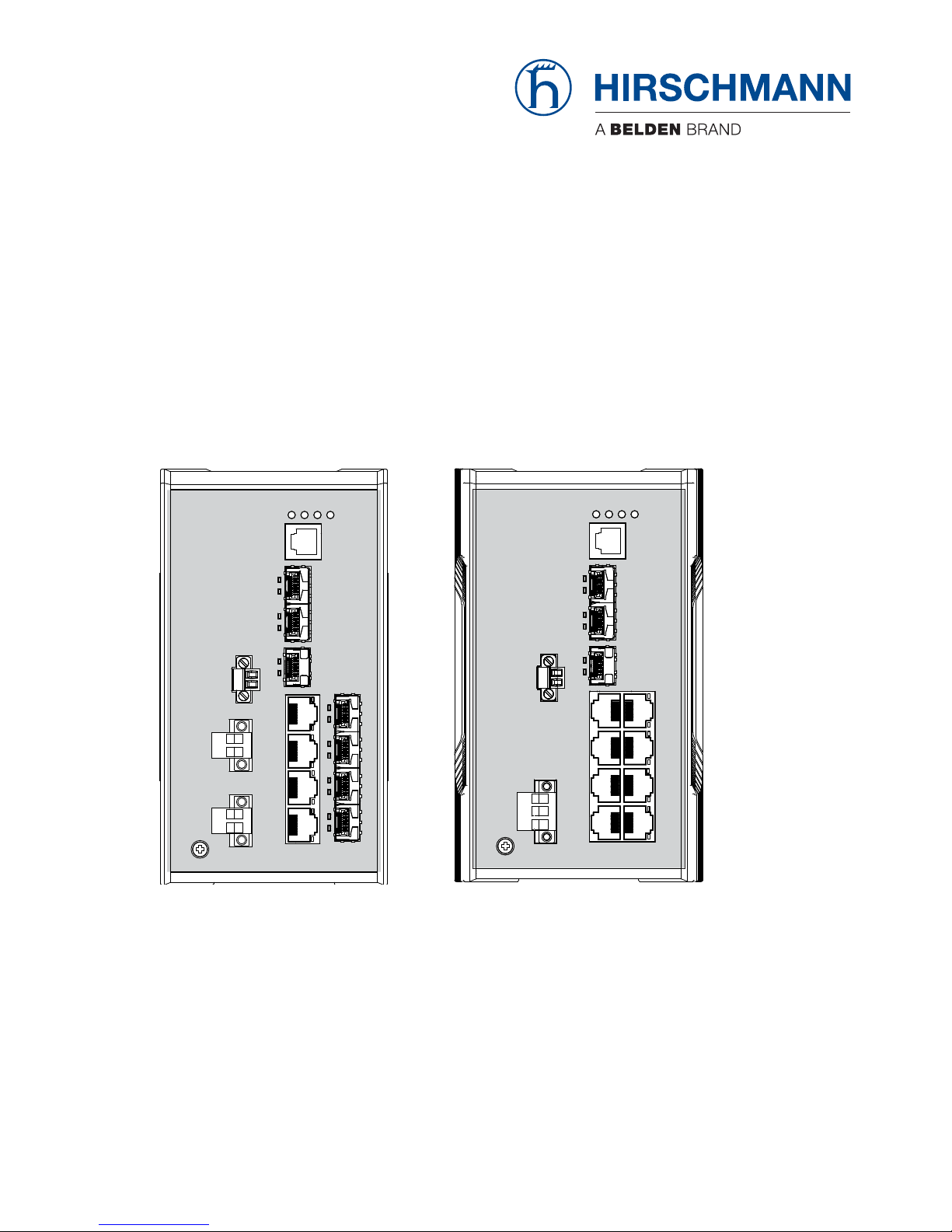
1.3 Device views 22
1.3.1 Front view 22
1.3.2 Rear view 23
1.4 Power supply 24
1.4.1 Supply voltage with the characteristic value K9 24
1.4.2 Supply voltage with the characteristic value KK 24
1.4.3 Supply voltage with the characteristic value TT 24
1.4.4 Supply voltage with the characteristic value CC 24
1.5 Ethernet ports 25
1.5.1 10/100 Mbit/s twisted pair port 25
1.5.2 100/1000 Mbit/s twisted pair port (optional) 25
1.5.3 100 Mbit/s F/O port 25
1.5.4 100/1000 Mbit/s F/O port (optional) 26
1.5.5 Pin assignments 26
1.6 Display elements 27
1.6.1 Device state 27
1.6.2 Port status 28
1.7 Management interfaces 29
1.7.1 V.24 interface (external management) 29
1.7.2 SD card interface 29
1.8 Signal contact 30
2 Installation 31
2.1 Checking the package contents 31
2.2 Installing the SD card (optional) 32
2.3 Installing and grounding the device 32
2.3.1 Installing the device onto the DIN rail 33
2.3.2 Grounding the device 34
2.4 Installing an SFP transceiver (optional) 34

4
Installation RSP 20/25/30/35
Release 15 12/2017
2.5 Connecting the terminal blocks 35
2.5.1 Supply voltage with the characteristic value K9 35
2.5.2 Supply voltage with the characteristic value KK 37
2.5.3 Supply voltage with the characteristic value CC 39
2.5.4 Supply voltage with the characteristic value TT 40
2.5.5 Signal contact 41
2.6 Operating the device 41
2.7 Connecting data cables 42
2.8 Filling out the inscription label 42
3 Making basic settings 43
4 Upgrading Software 44
5 Monitoring the ambient air temperature 45
6 Maintenance and service 46
7Disassembly 47
7.1 Removing the device 47
7.2 Removing an SFP transceiver (optional) 48
8 Technical data 49
8.1 General technical data 49
8.2 Power consumption/power output 52
8.3 Dimension drawings 53
8.4 EMC and immunity 54
8.5 Network range 57
8.6 Scope of delivery, order numbers and accessories 60
9 Underlying technical standards 63
A Further support 64
Installation RSP 20/25/30/35
Release 15 12/2017
5
Safety instructions
General safety instructions
You operate this device with electricity. Improper usage of the device
entails the risk of physical injury or significant property damage. The
proper and safe operation of this device depends on proper handling
during transportation, proper storage and installation, and careful
operation and maintenance procedures.
Before connecting any cable, read this document, and the safety
instructions and warnings.
Operate the device with undamaged components exclusively.
The device is free of any service components. In case of a damaged
or malfunctioning the device, turn off the supply voltage and return the
device to Hirschmann for inspection.
Certified usage
Use the product only for the application cases described in the
Hirschmann product information, including this manual.
Operate the product only according to the technical specifications.
See “Technical data” on page 49.
Connect to the product only components suitable for the requirements
of the specific application case.
Installation site requirements
Install the device in a fire enclosure according to EN 60950-1.
Only for device variants featuring supply voltage with characteristic
value K9 or KK:
Install this device solely in a switch cabinet or in an operating site with
restricted access, to which maintenance staff have exclusive access.
Install the device at ambient temperatures greater than 113 °F (45 °C)
in “restricted access locations” based on EN 60950-1 exclusively.
WARNING
UNCONTROLLED MACHINE ACTIONS
To avoid uncontrolled machine actions caused by data loss, configure all
the data transmission devices individually.
Before you start any machine which is controlled via data transmission, be
sure to complete the configuration of all data transmission devices.
Failure to follow these instructions can result in death, serious injury,
or equipment damage.

6
Installation RSP 20/25/30/35
Release 15 12/2017
Device casing
Only technicians authorized by the manufacturer are permitted to open
the housing.
Never insert pointed objects (narrow screwdrivers, wires, etc.) into the
device or into the connection terminals for electric conductors. Do not
touch the connection terminals.
Keep the ventilation slits free to ensure good air circulation.
Mount the device in the vertical position.
At ambient temperatures > 140 °F (60 °C):
The surfaces of the device housing may become hot. Avoid touching
the device while it is operating.
Qualification requirements for personnel
Only allow qualified personnel to work on the device.
Qualified personnel have the following characteristics:
Qualified personnel are properly trained. Training as well as practical
knowledge and experience make up their qualifications. This is the
prerequisite for grounding and labeling circuits, devices, and systems
in accordance with current standards in safety technology.
Qualified personnel are aware of the dangers that exist in their work.
Qualified personnel are familiar with appropriate measures against
these hazards in order to reduce the risk for themselves and others.
Qualified personnel receive training on a regular basis.
National and international safety regulations
Verify that the electrical installation meets local or nationally applicable
safety regulations.
Grounding the device
Grounding the device is by means of a separate ground connection on the
device.
Ground the device before connecting any other cables.
Disconnect the grounding only after disconnecting all other cables.
Ground the device via the ground screw.
Shielding ground
The overall shield of a connected shielded twisted pair cable is connected
to the ground connector on the front panel as a conductor.
Beware of possible short circuits when connecting a cable section with
conductive shielding braiding.
Requirements for connecting electrical wires
Before connecting the electrical wires, always verify that the
requirements listed are complied with.

Installation RSP 20/25/30/35
Release 15 12/2017
7
All of the following requirements are complied with:
The electrical wires are voltage-free.
The cables used are permitted for the temperature range of the application case.
Table 1: General requirements for connecting electrical wires
All of the following requirements are complied with:
The voltage connected complies with the requirements for a safety extra-low voltage
(SELV) as per IEC/EN 60950-1.
The connected voltage is limited by a current limitation device or a fuse.
Observe the electrical threshold values for the signal contact.
See “General technical data” on page 49.
Table 2: General requirements for connecting the signal contact
Device variant Requirements
All variants All of the following requirements are complied with:
The supply voltage corresponds to the voltage specified on the type
plate of the device.
The power supply conforms to overvoltage category I or II.
The power supply has an easily accessible disconnecting device (for
example a switch or a plug). This disconnecting device is clearly
identified. So in the case of an emergency, it is clear which
disconnecting device belongs to which power supply cable.
The cross-section of the ground conductor is the same size as or
bigger than the cross-section of the power supply cables.
Relevant for North America:
The power supply cables are suitable for ambient air temperatures of
at least 167 °F (75 °C). The power supply cable wires are made of
copper.
Only for device
variants featuring
supply voltage with
the characteristic
value CC:
The wire diameter of the power supply cable is at least 0.75 mm² (North
America: AWG18) on the supply voltage input.
The following requirements are alternatively complied with:
Alternative 1 The power supply complies with the requirements
for a limited power source (LPS) as per EN 60950-1.
Alternative 2 Relevant for North America:
The power supply complies with the requirements
according to NEC Class 2.
Alternative 3 All of the following requirements are complied with:
The power supply complies with the
requirements for a safety extra-low voltage
(SELV) as per IEC/EN 60950-1.
A fuse suitable for DC voltage is located in the
plus conductor of the power supply.
The minus conductor is on ground potential.
Otherwise, a fuse is also located in the minus
conductor.
Regarding the properties of this fuse:
See “General technical data” on page 49.
Table 3: Requirements for connecting the supply voltage

8
Installation RSP 20/25/30/35
Release 15 12/2017
Supply voltage
The supply voltage is connected to the device casing through protective
elements exclusively.
For supply voltage connections with protective conductor connection:
First connect the protective conductor before connecting the wires for
the supply voltage.
For device variants featuring supply voltage with characteristic value
CC and TT:
For the redundant power supply, only use voltage sources whose
negative terminal is grounded. The use of different voltage sources
can lead to equipment damage.
Only device variants
featuring supply
voltage with
characteristic value
TT:
The wire diameter of the power supply cable is at least 0.75 mm² (North
America: AWG18) on the supply voltage input.
The following requirements are alternatively complied with:
Alternative 1 The power supply complies with the requirements
for a limited power source (LPS) as per EN 60950-1.
Alternative 2 All of the following requirements are complied with:
The power supply complies with the
requirements for a safety extra-low voltage
(SELV) as per IEC/EN 60950-1.
A fuse suitable for DC voltage is located in the
plus conductor of the power supply.
The minus conductor is on ground potential.
Otherwise, a fuse is also located in the minus
conductor.
Regarding the properties of this fuse:
See “General technical data” on page 49.
Alternative 3 Relevant for North America:
The power supply complies with the requirements
according to NEC Class 2.
Only for device
variants featuring
supply voltage with
characteristic
value K9 or KK:
All of the following requirements are complied with:
Supply with DC voltage:
A fuse suitable for DC voltage is located in the plus conductor of the
power supply.
The minus conductor is on ground potential. Otherwise, a fuse is also
located in the minus conductor.
Regarding the properties of this fuse:
See “General technical data” on page 49.
The wire diameter of the power supply cable is at least 1 mm² (North
America: AWG16) on the supply voltage input.
Supply with AC voltage:
A fuse is located in the outer conductor of the power supply.
The neutral conductor is on ground potential at both voltage inputs.
Otherwise, a fuse is also located in the neutral conductor.
Regarding the properties of this fuse:
See “General technical data” on page 49.
The wire diameter of the power supply cable is at least 0.75 mm²
(North America: AWG18) on the supply voltage input.
Device variant Requirements
Table 3: Requirements for connecting the supply voltage
Installation RSP 20/25/30/35
Release 15 12/2017
9
ATEX directive 2014/34/EU – specific regulations for safe
operation
Relevant for RSP devices when operating in explosive gas atmospheres
according to ATEX directive 2014/34/EU, the following applies:
List of standards:
EN 60079-0:2012, A11:2013
EN 60079-15:2010
Certificate No.: DEKRA 15ATEX0017X
Use only device variants featuring supply voltage with characteristic
value CC.
Make sure that the device has the following label:
II 3G Ex nA IIC T4 Gc DEKRA 15ATEX0017X
Ambient rating and temperature code for RSP types:
T4: 0 °C ≤ Ta ≤ +60 °C for “S” types or
T4: −40 °C ≤ Ta ≤ +70 °C for “T” or “E” types
The modules shall be installed in a suitable enclosure in accordance
with IEC 60079-15 providing a degree of protection of at least IP54
according to IEC 60529, taking into account the environmental
conditions under which the equipment will be used.
When the temperature under rated conditions exceeds 158 °F (70 °C)
at the cable or conduit entry point, or 176 °F (80 °C) at the branching
point of the conductors, the temperature specification of the selected
cable and cable entries shall be in compliance with the actual
measured temperature values.
Provisions shall be made to prevent the rated voltage from being
exceeded by transient disturbances of more than 119 V.
Connectors shall be connected or disconnected exclusively in dead-
voltage state.
The USB port shall remain disconnected.

10
Installation RSP 20/25/30/35
Release 15 12/2017
Relevant for use in explosion hazard areas (Hazardous
Locations, Class I, Division 2):
The relay connections are to be installed and used within their Entity
Parameters as per Control Drawing 000189237DNR.
Avertissement - Risque d'explosion - Ne pas débrancher tant que le
circuit est sous tension à moins que l'emplacement soit connu pour ne
contenir aucune concentration de gaz inflammable.
Avertissement - Risque d'explosion - La substitution de tout composant
peut rendre ce matériel incompatible pour une utilisation en classe I,
division 2.

Installation RSP 20/25/30/35
Release 15 12/2017
11
Control Drawing for RSP devices according to Class I Division 2 Hazardous Locations
Rev.: 0 Document No.: 000189237DNR Page 1/2
For Use in Hazardous Locations Class I Division 2 Groups A, B, C, D:
Only allowed for RSP 20/25/30/35 model No´s. which are individually labeled
“FOR USE IN HAZARDOUS LOCATIONS”.
Nonincendive fi eld wiring circuits must be wired in accordance with the National Electrical Code
(NEC), NFPA 70, article 501; CEC, Appendix J, Annex J18.
The earth conductor must be at least of the same wire size (mm² or AWG)
as the supply conductors.
WARNING – EXPLOSION HAZARD
Substitution of any components may impair suitability for hazardous locations or explosive
atmospheres.
WARNING – EXPLOSION HAZARD
Do not disconnect equipment unless power has been switched off or the area is known to be
known to be non-hazardous.
12
Installation RSP 20/25/30/35
Release 15 12/2017
Control Drawing for RSP devices according to Class I Division 2 Hazardous Locations
Rev.: 0 Document No.: 000189237DNR Page 2/2
Ordinary Location,
Non-Hazardous Area,
Non-Explosive Atmosphere
Explosive Atmosphere
Class I Division 2
Groups A, B, C, D
Hazardous Location
RSP
Relay
Power Supply unit type CC: 24 VDC - 48 VDC
Power Supply unit type K9: 110 VAC - 230 VAC or
60 VDC - 250 VDC
Power Supply unit type KK: 2x 110 VAC - 230 VAC or
2x 60 VDC - 250 VDC
(Refer to the power supply code of the type designation on the device.)
Temperature Code: T4
Ambient Temperature rating:
Ta: 0 °C to +60 °C for “S” temperature types
Ta: í40 °C to +70 °C for “T” or “E” temperature types
(Refer to the temperature code of the type designation on the device.)
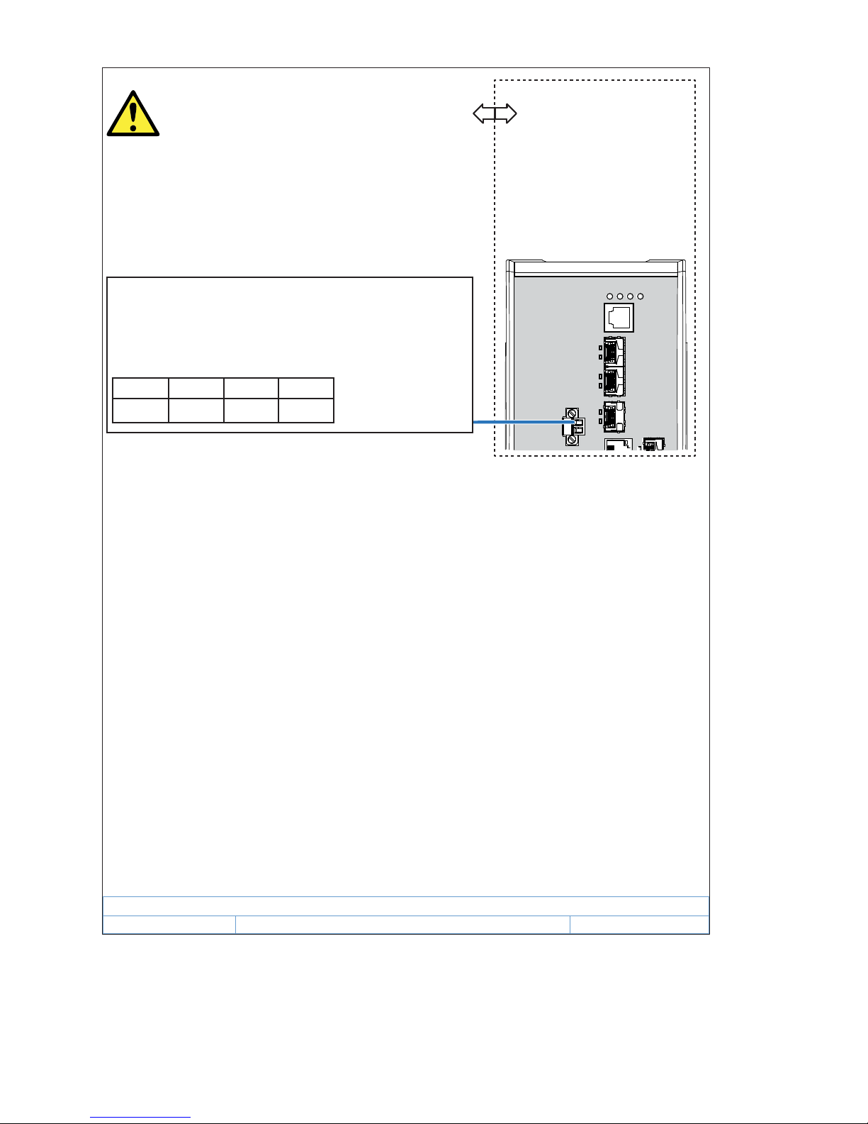
Relay contacts:
Equipment with nonincendive eld wiring parameters.
Polarity is not relevant.
The relay terminals are dependent upon the following
Entity parameters:
U
i
I
i
C
i
L
i
30 V 90 mA 2 nF 1 H
Installation RSP 20/25/30/35
Release 15 12/2017
13
IECEx – Certification Scheme for Explosive Atmospheres
For RSP devices labeled with an IECEx certificate number, the following
applies:
List of standards:
IEC 60079-0:2011+Cor.2012+Cor.2013
IEC 60079-15:2010
The equipment shall only be used in an area of not more than pollution
degree 2, as defined in IEC 60664-1.
Make sure that the device has the following label:
Ex nA IIC T4 Gc IECEx DEK 15.0014X
Environmental class and temperature code for RSP types:
T4: 0 °C ≤ Ta ≤ +60 °C for “S“ types or
T4: −40 °C ≤ Ta ≤ +70 °C for “T“ or “E“ types
The modules shall be installed in a suitable enclosure in accordance
with IEC 60079-15 providing a degree of protection of at least IP54
according to IEC 60529, taking into account the environmental
conditions under which the equipment will be used.
When the temperature under rated conditions exceeds 158 °F (70 °C)
at the cable or conduit entry point, or 176 °F (80 °C) at the branching
point of the conductors, the temperature specification of the selected
cable and cable entries shall be in compliance with the actual
measured temperature values.
Provisions shall be made to prevent the rated voltage from being
exceeded by transient disturbances of more than 119 V.
Connectors shall be connected or disconnected exclusively in dead-
voltage state.
The USB port shall remain disconnected.

14
Installation RSP 20/25/30/35
Release 15 12/2017
CE marking
The labeled devices comply with the regulations contained in the following
European directive(s):
In accordance with the above-named EU directive(s), the EU conformity
declaration will be at the disposal of the relevant authorities at the
following address:
Hirschmann Automation and Control GmbH
Stuttgarter Str. 45-51
72654 Neckartenzlingen
Germany
The product can be used in the industrial sector.
Interference immunity: EN 61000-6-2
Emitted interference: EN 55032
Reliability: EN 60950-1
You find more information on technical standards here:
“Technical data” on page 49
Warning! This is a class A device. This device can cause interference in
living areas, and in this case the operator may be required to take
appropriate measures.
Note: The assembly guidelines provided in these instructions must be
strictly adhered to in order to observe the EMC threshold values.
LED or laser components
LED or LASER components according to IEC 60825-1 (2014):
CLASS 1 LASER PRODUCT
CLASS 1 LED PRODUCT
Device variant Directive
All variants 2014/30/EU (EMC)
Directive of the European Parliament and of the Council on the
harmonisation of the laws of the Member States relating to
electromagnetic compatibility.
2011/65/EU (RoHS)
Directive of the European Parliament and of the Council on the
restriction of the use of certain hazardous substances in
electrical and electronic equipment.
Only for device variants
featuring supply voltage with
characteristic value K9 or KK:
2014/35/EU
Directive of the European Parliament and of the Council on the
harmonisation of the laws of the Member States relating to the
making available on the market of electrical equipment
designed for use within certain voltage limits.

Installation RSP 20/25/30/35
Release 15 12/2017
15
FCC note:
This device complies with part 15 of the FCC rules. Operation is subject
to the following two conditions: (1) this device may not cause harmful
interference; (2) this device must accept any interference received,
including interference that may cause undesired operation.
Appropriate testing has established that this device fulfills the
requirements of a class A digital device in line with part 15 of the FCC
regulations.
These requirements are designed to provide sufficient protection against
interference when the device is being used in a business environment.
The device creates and uses high frequencies and can also radiate these
frequencies. If it is not installed and used in accordance with this
operating manual, it can cause radio transmission interference. The use
of this device in a residential area can also cause interference, and in this
case the user is obliged to cover the costs of removing the interference.
Recycling note
After usage, this device must be disposed of properly as electronic waste,
in accordance with the current disposal regulations of your county, state,
and country.

16
Installation RSP 20/25/30/35
Release 15 12/2017
About this manual
The “Installation” user manual contains a device description, safety
instructions, a description of the display, and the other information that you
need to install the device.
The following manuals are available as PDF files on the Internet on the
Hirschmann product pages (www.hirschmann.com):
Installation user manual
Basic Configuration user manual
Redundancy Configuration user manual
Reference manual for the graphical user interface
Command Line Interface reference manual

Installation RSP 20/25/30/35
Release 15 12/2017
17
Key
The symbols used in this manual have the following meanings:
Listing
Work step
Subheading

18
Installation RSP 20/25/30/35
Release 15 12/2017
1 Description
1.1 General description
The RSP 20/25/30/35 devices are designed for the special requirements of
industrial automation. They meet the relevant industry standards, provide
very high operational reliability, even under extreme conditions, and also
long-term reliability and flexibility.
You can choose from between a wide range of variants. You have the option
to set up your device individually based on different criteria:
Number of ports
Transmission speed
Types of connectors
Temperature range
Supply voltage range
Certifications
Redundancy functions
You have the option of choosing various media to connect to the end devices
and other network components:
Multimode optical fiber
Singlemode optical fiber
Twisted pair cable
The device is mounted by latching in place on a DIN rail.
The devices work without a fan.
The redundancy concept allows the network to be reconfigured quickly.
There are convenient options for managing the device. Manage your devices
via:
a Web browser
SSH
Telnet
HiDiscovery (Software for putting the device into operation)
a V.24 interface (locally on the device)
a network management software (for example Industrial HiVision)
The devices provide you with a large range of functions, which the manuals
for the operating software inform you about. You find these manuals in the
form of PDF files for downloading on the Internet on the Hirschmann product
pages (www.hirschmann.com).

Installation RSP 20/25/30/35
Release 15 12/2017
19
The Hirschmann network components help you ensure continuous
communication across all levels of the company.
1.2 Device name and product code
The device name corresponds to the product code. The product code is
made up of characteristics with defined positions. The characteristic values
stand for specific product properties.
You have numerous options of combining the device characteristics. You can
determine the possible combinations using the Configurator which is
available in the Belden E-Catalog (www.e-catalog.beldensolutions.com) on
the web page of the device.
Item Characteristic Character
istic value
Description
1 ... 5 Product RSP20 Fast Ethernet switch
RSP25 Fast Ethernet switch with extended redundancy
function
RSP30 Gigabit Ethernet switch
RSP35 Gigabit Ethernet switch with extended
redundancy function
6 (hyphen) –
7 ... 8 Number
Fast Ethernet ports
08 8 ×
11 11 ×
9 ... 10 Number
Gigabit Ethernet ports
00 0 ×
03 3 ×
11 ... 13 Configuration of the
uplink ports
3Z6 3 × Optional SFP slot for:
100 Mbit/s twisted pair connections
100 Mbit/s F/O connections
3O6 3 × Optional SFP slot for:
100 Mbit/s twisted pair connections
1000 Mbit/s twisted pair connections
100 Mbit/s F/O connections
1000 Mbit/s F/O connections
14 ... 15 Configuration of the
other ports
TT 8 × RJ45 socket for 10/100 Mbit/s twisted pair
connections
ZT 4 × RJ45 socket for 10/100 Mbit/s twisted pair
connections
4 × Optional SFP slot for:
100 Mbit/s twisted pair connections
100 Mbit/s F/O connections
16 (hyphen) –
Table 4: Device name and product code

20
Installation RSP 20/25/30/35
Release 15 12/2017
17 Temperature range S Standard +32 °F ... +140 °F
(0 °C ... +60 °C)
T Extended −40 °F ... +158 °F
(−40 °C ... +70 °C)
E Extended with
Conformal Coating
−40 °F ... +158 °F
(−40 °C ... +70 °C)
18 ... 19 Supply voltage CC 2 voltage inputs for redundant power supply
Rated voltage range DC
24 V DC ... 48 V DC
K9 1 voltage input
Rated voltage range AC
110 V AC ... 230 V AC, 50 Hz ... 60 Hz
Rated voltage range DC
60 V DC ... 250 V DC
KK 2 voltage inputs for redundant power supply
Rated voltage range AC
110 V AC ... 230 V AC, 50 Hz ... 60 Hz
Rated voltage range DC
60 V DC ... 250 V DC
TT 2 voltage inputs for redundant power supply
Rated voltage range DC
12 V DC ... 24 V DC
20 ... 21 Certificates and
declarations
You will find detailed information on the certificates and
declarations applying to your device in a separate overview.
See table 5 on page 21.
22 ... 23 Customer-specific
version
HS Hirschmann Standard
HM Hirschmann Fast MRP
HP Hirschmann PRP
HH Hirschmann HSR
HD From software version 05.0 onward:
Hirschmann DLR
Note: You can exchange software with each other on the
following device variants:
HM
HP
HH
24 Software
configuration
E Entry (without configuration)
25 ... 26 Software level 2S HiOS Layer 2 Standard
2A HiOS Layer 2 Advanced
3S HiOS Layer 3 Standard
27 ... 31 Software version 02.0. Software version 02.0
XX.X. Current software version
Item Characteristic Character
istic value
Description
Table 4: Device name and product code
 Loading...