

Page 1
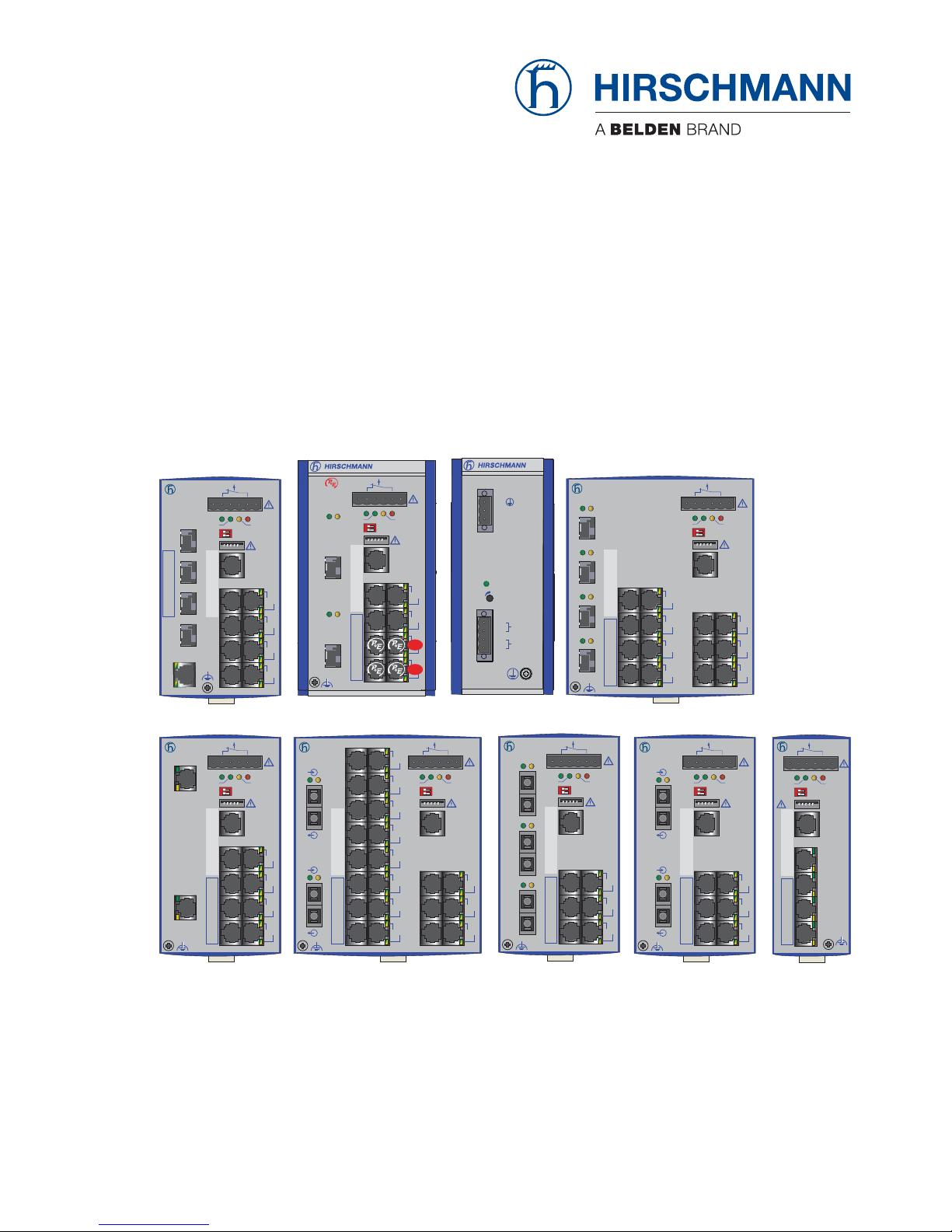
Installation RS20/22/30/32/40
Release 05 12/2015
Technical support
https://hirschmann-support.belden.eu.com
User Manual
Installation
Industrial ETHERNET Rail Switch
RS20/RS22/RS30/RS32/RS40 Family
RS30-0802...
RS30
RM
+24V(P1) 0V 0V
FAULT
+24V(P2)
Stand by
Aufkleber MAC-Adresse
IP-ADDRESS
3
5
7
9
4
6
8
10
V.24
USB
P
Stand by
FAULT
RM
ON
LS
2
DA
LS
1
DA
RS30-1602...
RS20
+24V(P1) 0V 0V
FAULT
+24V(P2)
4
6
8
5
7
9
LS DA
2
LS DA
1
LS DA
3
RS30
+24V(P1) 0V 0V
FAULT
+24V(P2)
5
7
9
11
6
8
10
12
13
15
17
14
16
18
LS DA
1
LS DA
2
LS DA
3
LS DA
4
RS20
LS DA
RM
+24V(P1) 0V 0V
FAULT
+24V(P2)
Stand by
Aufkleber MAC-Adresse
IP-ADDRESS
3
5
7
9
11
13
15
17
2
LS DA
1
4
6
8
10
12
14
16
18
19
21
23
20
22
24
V.24
USB
P
Stand by
FAULT
RM
ON
RS20
LS DA
RM
+24V(P1) 0V 0V
FAULT
+24V(P2)
Stand by
Aufkleber MAC-Adresse
IP-ADDRESS
2
LS DA
1
3
5
7
4
6
8
V.24
USB
P
Stand by
FAULT
RM
ON
RS20
RM
Stand by
Aufkleber MAC-Adresse
IP-ADDRESS
V.24
USB
P
Stand by
FAULT
RM
ON
LS
1
DA
LS
2
DA
LS
3
DA
LS
4
DA
RS20-0800...RS20-2400... RS20-0400...
RM
Stand by
Aufkleber MAC-Adresse
IP-ADDRESS
V.24
USB
P
Stand by
FAULT
RM
ON
RM
Stand by
Aufkleber MAC-Adresse
IP-ADDRESS
V.24
USB
P
Stand by
FAULT
RM
ON
RS20-0900...
RS40
+24V(P1) 0V 0V
FAULT
+24V(P2)
1
3
5
7
2
4
6
8
1
2
3
4
RM
Stand by
Aufkleber MAC-Adresse
IP-ADDRESS
V.24
USB
P
Stand by
FAULT
RM
ON
9
RS40-0009... RS32-0802... RPS90/48V HV
RPS90/48V HV
U: 110 / 230 VAC
U: 60 / 250 VDC
-/N
+/L
0V
+48V / 1,9A
48-54V
P
RS32
1
GB
2
GB
RM
Stand by
Aufkleber MAC-Adresse
IP-ADDRESS
V.24
USB
P
Stand by
FAULT
RM
ON
LS DA
LS DA
3
5
7
9
4
6
8
10
+24V(P1) 0V 0V
FAULT
+24V(P2)
FAULT
+48V(P1) 0V 0V +48V(P2)
Page 2

The naming of copyrighted trademarks in this manual, even when not specially indicated, should
not be taken to mean that these names may be considered as free in the sense of the trademark
and tradename protection law and hence that they may be freely used by anyone.
© 2015 Hirschmann Automation and Control GmbH
Manuals and software are protected by copyright. All rights reserved. The copying, reproduction,
translation, conversion into any electronic medium or machine scannable form is not permitted,
either in whole or in part. An exception is the preparation of a backup copy of the software for
your own use. For devices with embedded software, the end-user license agreement on the
enclosed CD/DVD applies.
The performance features described here are binding only if they have been expressly agreed
when the contract was made. This document was produced by Hirschmann Automation and
Control GmbH according to the best of the company's knowledge. Hirschmann reserves the right
to change the contents of this document without prior notice. Hirschmann can give no guarantee
in respect of the correctness or accuracy of the information in this document.
Hirschmann can accept no responsibility for damages, resulting from the use of the network
components or the associated operating software. In addition, we refer to the conditions of use
specified in the license contract.
You can get the latest version of this manual on the Internet at the Hirschmann product site
(www.hirschmann.com).
Hirschmann Automation and Control GmbH
Stuttgarter Str. 45-51
72654 Neckartenzlingen
Germany
Tel.: +49 1805 141538
RS20/22/30/32/40 039 692-003-05-1215
Page 3

Installation RS20/22/30/32/40
Release 05 12/2015
3
Contents
Safety instructions 5
About this Manual 18
Key 18
1 Description 19
1.1 Description of the device variants 21
1.1.1 Combination options of the device variants
RS20/RS30/RS22/RS32 23
1.1.2 Combination options for the RS40 device variants 26
1.1.3 Number of ports and media for RS20-... 27
1.1.4 Number of ports and media for RS30-... 31
1.1.5 Number of ports and media for RS40-... 34
1.2 Device variants with PoE (optional) 35
1.2.1 Number of ports and media for devices with PoE 35
1.2.2 PoE power units 37
1.3 Ethernet ports 38
1.3.1 10/100/1000 Mbit/s twisted pair port 38
1.3.2 10/100 Mbit/s twisted pair port 39
1.3.3 10/100 Mbit/s twisted-pair connection PoE
(RS22-.../RS32-...) 39
1.3.4 1000 Mbit/s F/O port 40
1.3.5 100 Mbit/s F/O port 40
1.3.6 Gigabit combo port 41
1.4 Display elements 42
1.5 Management interfaces 44
1.5.1 USB interface 44
1.5.2 V.24 interface (external management) 44
2 Installation 45
2.1 Checking the package contents 46
2.2 Installing and grounding the device 46
2.2.1 Installing the device onto the DIN rail 46
2.2.2 DIN rail mounting on ships (RS30-0802...) 48
2.2.3 Mounting on a vertical flat surface 49
2.2.4 Grounding the device 49
2.3 Installing an SFP transceiver (optional) 50
2.4 Adjust DIP switch settings 50
Page 4

4
Installation RS20/22/30/32/40
Release 05 12/2015
2.5 Connecting the terminal block 51
2.5.1 RS20/RS30/RS40: supply voltage and signal contact 51
2.5.2 RS22/RS32: supply voltage and signal contact 53
2.6 Mounting the terminal block 56
2.7 Connecting the ferrite 57
2.8 Operating the device 57
2.9 Connecting data cables 58
2.10 Filling out the inscription label 58
3 Making basic settings 59
4 Monitoring the ambient air temperature 60
5 Maintenance and service 61
6Disassembly 62
6.1 Removing the device 62
6.2 Removing an SFP transceiver (optional) 63
7 Technical data 64
A Further Support 78
Page 5
Installation RS20/22/30/32/40
Release 05 12/2015
5
Safety instructions
General safety instructions
You operate this device with electricity. Improper usage of the device
entails the risk of physical injury or significant property damage. The
proper and safe operation of this device depends on proper handling
during transportation, proper storage and installation, and careful
operation and maintenance procedures.
Before connecting any cable, read this document, and the safety
instructions and warnings.
Operate the device with undamaged components exclusively.
The device is free of any service components. In case of a damaged
or malfunctioning the device, turn off the supply voltage and return the
device to Hirschmann for inspection.
Certified usage
Use the device solely for the application cases described in the
Hirschmann product information, including this manual.
Operate the device solely according to the technical specifications.
See “Technical data” on page 64.
Installation site requirements
Install the device in a fire enclosure according to EN 60950-1.
If installed in a living area or office environment, the device must be
operated only in switch cabinets with fire protection characteristics
according to EN 60950-1.
Only when using the PoE power supply unit RPS90/48V HV:
Install the device at ambient temperatures greater than 113 °F (45 °C)
in “restricted access locations” based on EN 60950-1 exclusively.
Install this device solely in a switch cabinet or in an operating site with
restricted access, to which maintenance staff have exclusive access.
WARNING
UNCONTROLLED MACHINE ACTIONS
To avoid uncontrolled machine actions caused by data loss, configure all
the data transmission devices individually.
Before you start any machine which is controlled via data transmission, be
sure to complete the configuration of all data transmission devices.
Failure to follow these instructions can result in death, serious injury,
or equipment damage.
Page 6

6
Installation RS20/22/30/32/40
Release 05 12/2015
Device casing
Only technicians authorized by the manufacturer are permitted to open
the housing.
Never insert pointed objects (narrow screwdrivers, wires, etc.) into the
device or into the connection terminals for electric conductors. Do not
touch the connection terminals.
Keep the ventilation slits free to ensure good air circulation.
See “General technical data” on page 64.
Install the device in the vertical position.
At ambient temperatures > 140 °F (60 °C):
The surfaces of the device housing may become hot. Avoid touching
the device while it is operating.
Qualification requirements for personnel
Only allow qualified personnel to work on the device.
Qualified personnel have the following characteristics:
Qualified personnel are properly trained. Training as well as practical
knowledge and experience make up their qualifications. This is the
prerequisite for grounding and labeling circuits, devices, and systems
in accordance with current standards in safety technology.
Qualified personnel are aware of the dangers that exist in their work.
Qualified personnel are familiar with appropriate measures against
these hazards in order to reduce the risk for themselves and others.
Qualified personnel receive training on a regular basis.
National and international safety regulations
Verify that the electrical installation meets locally or nationally applicable
safety regulations.
Grounding the device
The housing is grounded via the separate ground screw on the bottom left
of the front panel.
Use a wire diameter for the ground conductor that is no smaller than
the diameter of the supply voltage connection, however of at least 1.0
mm² (AWG16).
Ground the device before connecting any other cables.
Disconnect the grounding only after disconnecting all other cables.
Shielding ground
The overall shield of a connected shielded twisted pair cable is connected
to the ground connector on the front panel as a conductor.
Beware of possible short circuits when connecting a cable section with
conductive shielding braiding.
Page 7

Installation RS20/22/30/32/40
Release 05 12/2015
7
Supply voltage
The supply voltage is electrically isolated from the housing.
The devices are designed for operation with safety extra-low voltage.
Connect only SELV circuits with voltage restrictions in line with IEC/EN
60950-1 to the supply voltage connections and signal contacts.
Connect only a supply voltage that corresponds to the type plate of
your device.
Observe the maximum values for the contact load of the signal
contact.
Relevant for North America:
The device may only be connected to a Class 2 supply voltage that
fulfills the requirements of the National Electrical Code, Table 11(b). If
the voltage is being supplied redundantly (two different voltage
sources), the combined supply voltages must fulfill the requirements of
the National Electrical Code, Table 11(b).
Relevant for North America: For use in class 2 circuits.
Use 60/75 °C (140/167 °F) or 75 °C (167 °F) copper (Cu) wire only.
Relevant for North America
for devices certified for hazardous locations:
Power, input and output (I/O) wiring must be in accordance with
Class I, Division 2 wiring methods [Article 501-4(b) of the National
Electrical Code, NFPA 70] and in accordance with the authority having
jurisdiction.
Start connecting the electrical wires only if all the above safety
requirements are fulfilled.
Enable the supply voltage for the device only when the following
requirements are fulfilled:
the housing is closed
the terminal blocks are wired correctly
the terminal blocks for the power supply are connected
Internal fuses are triggered only in the case of a detected error in the
device. In case of damage or malfunction of the device, turn off the
supply voltage and return the device to the plant for inspection.
Page 8

8
Installation RS20/22/30/32/40
Release 05 12/2015
Supply voltage for PoE power supply units (optional)
Connect the protective conductor with the ground screw before you set
up the other connections. When removing the cables, remove the
protective conductor last.
Make sure that the cross-section of the protective conductor cable is
the same size as or bigger than the cross-section of the voltage supply
cables.
Only use connection cables that are permitted for the specified
temperature range.
Connect only a supply voltage that corresponds to the type plate of
your device.
PoE power supply unit RPS90/48V LV:18 V DC to 60 V DC
PoE power supply unit RPS90/48V HV:48 V DC to 320 V DC or 90
V AC to 265 V AC
Install a suitable input fuse in the following cases:
The neutral conductor or the negative terminal of the supply voltage
is ungrounded.
For the supply voltage, you provide a DC voltage greater than
125 V DC.
See “General technical data” on page 64.
With AC power supply, use a cable cross-section of at least 0.75 mm²
(for North America AWG 18) for the current conductor at the voltage
input.
With DC power supply, use a cable cross-section of at least 1.0 mm²
(for North America AWG 16) for the current conductor at the voltage
input.
Page 9

Installation RS20/22/30/32/40
Release 05 12/2015
9
ATEX directive 94/9/EG – specific regulations for safe
operation
Relevant for RS20/22/30/32/40 devices when operating in explosive gas
atmospheres according to ATEX Directive 94/9 EC, the following applies:
List of standards:
EN 60079-0:2012 + A11:2013
EN 60079-15:2010
Certificate No.: DEKRA 11ATEX0139 X or KEMA 09ATEX0067 X.
Make sure that the device has the following label:
II 3G Ex nA IIC T4 Gc DEKRA 11ATEX0139 X
for RS20/22/30/32 types.
II 3G Ex nA IIC T3 ... T4 Gc KEMA 09ATEX0067 X
for RS40 types.
Ambient rating and temperature code for RS20 and RS30 types:
T4: 0 °C ≤ Ta ≤ +60 °C for “S” types
(item 14 of nomenclature breakdown) or
T4: −40 °C ≤ Ta ≤ +70 °C for “T” or “E” types
(item 14 of nomenclature breakdown).
Ambient rating and temperature code for RS22 and RS32 types:
T4: −40 °C ≤ Ta ≤ +50 °C for “T” or “E” types
(item 14 of nomenclature breakdown) or
T4: 0 °C ≤ Ta ≤ +50 °C for “S” types
(item 14 of nomenclature breakdown)
Ambient rating and temperature code for RS40 types:
T3: −40 °C ≤ Ta ≤ +70 °C for “T” or “E” types
(item 14 of nomenclature breakdown).
T4: −40 °C ≤ Ta ≤ +60 °Cfor “T” or “E” types
(item 14 of nomenclature breakdown).
T4: 0 °C ≤ Ta ≤ +60 °C for “S” types
(item 14 of nomenclature breakdown).
The modules shall be installed in a suitable enclosure in accordance
with EN 60079-15 providing a degree of protection of at least IP54
according to EN 60529, taking into account the environmental
conditions under which the equipment will be used.
When the temperature under rated conditions exceeds 70 °C at the
cable or conduit entry point, or 80 °C at the branching point of the
conductors, the temperature specification of the selected cable and
cable entries shall be in compliance with the actual measured
temperature values.
Page 10

10
Installation RS20/22/30/32/40
Release 05 12/2015
Provisions shall be made to prevent the rated voltage from being
exceeded by transient disturbances of more than 119 V.
Connectors shall be connected or disconnected exclusively in dead-
voltage state.
DIP switches shall be switched exclusively in dead-voltage state.
The USB port shall remain disconnected.
Page 11

Installation RS20/22/30/32/40
Release 05 12/2015
11
Relevant for use in explosion hazard areas (Hazardous
Locations, Class I, Division 2):
Relevant for North America for devices certified for Hazardous Locations:
Power, input and output (I/O) wiring must be in accordance with Class I,
Division 2 wiring methods [Article 501-4(b) of the National Electrical
Code, NFPA 70] and in accordance with the authority having jurisdiction.
SUITABLE FOR USE IN CLASS I, DIVISION 2, GROUPS A, B, C AND D
HAZARDOUS LOCATIONS, OR NON-HAZARDOUS LOCATIONS
ONLY.
WARNING – EXPLOSION HAZARD – SUBSTITUTION OF ANY
COMPONENTS MAY IMPAIR SUITABLE FOR CLASS I, DIVISION 2.
WARNING – EXPLOSION HAZARD – DO NOT DISCONNECT
EQUIPMENT WHILE THE CIRCUIT IS LIVE OR UNLESS THE AREA IS
KNOWN TO BE FREE OF IGNITABLE CONCENTRATIONS.
The USB connector is for temporary connection only. Do not use,
connect, or disconnect unless area is known to be non-hazardous.
Connection or disconnection in an explosive atmosphere could result in
an explosion.
Peripheral equipment must be suitabel for the location it is used in.
Use 60/75 °C (140/167 °F) or 75 °C (167 °F) copper (Cu) wire only.
Avertissement - Risque d'explosion - Ne pas débrancher tant que le
circuit est sous tension à moins que l'emplacement soit connu pour ne
contenir aucune concentration de gaz inflammable.
Avertissement - Risque d'explosion - La substitution de tout composant
peut rendre ce matériel incompatible pour une utilisation en classe I,
division 2.
Page 12
12
Installation RS20/22/30/32/40
Release 05 12/2015
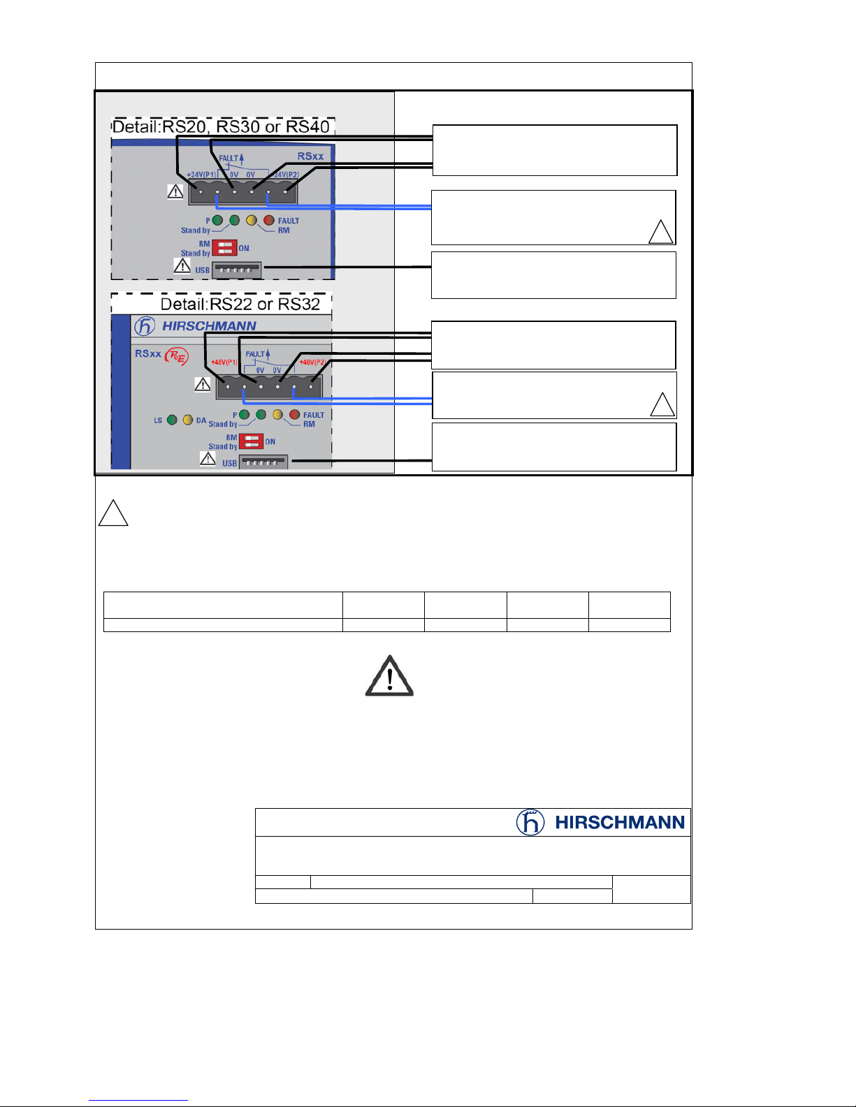
CONTROL DRAWING: Hazardous Locations Class I, Division 2, Groups A, B ,C ,D
Notes:
The nonincendive field wiring circuit concept allows interconnection of nonincendive field wiring apparatus
and associated nonincendive field wiring apparatus using any of the wiring methods permitted for
unclassified locations when certain parametric conditions are met.
C
a
Ci + C
Cable
; La Li + L
Cable
Nonincendive field wiring circuits must be wired in accordance with the National Electrical Code (NEC),
NFPA 70 , article 501.
Nonincendive Field Wiring Parameters:
Entity Parameters
... for Class I, Division 2, Groups A,B,C,D =>
V
max
[V]
I
max
[mA]
C
i
[nF]
L
i
[µH]
Fault contacts
30 90 2.5 1.0
WARNING - EXPLOSION HAZARD – SUBSTITUTION OF ANY COMPONENTS MAY IMPAIR
SUITABILITY FOR HAZARDOUS LOCATIONS OR EXPLOSIVE ATMOSPHERES.
WARNING - EXPLOSION HAZARD - DO NOT DISCONNECT EQUIPMENT UNLESS POWER HAS BEEN
SWITCHED OFF OR THE AREA IS KNOWN TO BE NON-HAZARDOUS.
DO NOT OPEN WHEN ENERGIZED.
:
CONTROL DRAWING for RS20, RS22, RS30, RS32 and RS40 Family
Size A4 Document No.: 000157671DNR Rev. 0
Date: 2011-09-21 Sheet 1 of 1
NON HAZARDOUS LOCATION
USB Port for Auto Configuration
Adapter.
P1
P2
HAZARDOUS LOCATION
Fault contacts. Equipment with nonincendive
field wiring parameters:
V<30V I<90mA L
i
<1,0µH Ci<2.5nF
USB Port for Auto Configuration Adapter.
For maintenance only – See Installation
Instructions
USB Port for Auto Configuration Adapter.
For maintenance only – See Installation
Instructions
Power supply (Redundant: P1 P2)
Type “P”: 48Vdc
(47Vdc min. … 52Vdc max.)
Fault contacts. Equipment with nonincendive
field wiring parameters:
V<30V I<90mA L
i
<1,0µH Ci<2.5nF
Power supply:
(Redundant: P1 P2)
Type “D”: 9.6Vdc – 60Vdc
P1
P2
P1
P2
Page 13

Installation RS20/22/30/32/40
Release 05 12/2015
13
IECEx – Certification Scheme for Explosive Atmospheres
For RS20/22/30/32/40 devices labeled with an IECEx certificate number,
the following applies:
List of standards:
IEC 60079-0:2011+ Corr. 2012 + Corr. 2013
IEC 60079-15:2010
The device is suitable for use in an area with a degree of soiling of 2
as per IEC 60664-1
.
Make sure that the device has the following label:
Ex nA IIC T4 Gc IECEx DEK 14.0077X
for RS20/22/30/32 types.
Ex nA IIC T3 ... T4 Gc IECEx DEK 14.0076X
for RS40 types.
Environmental class and temperature code for types RS20 and RS30:
T4: 0 °C ≤ Ta ≤ +60 °C for "S" types
(Item 14 in the schematic legend) or
T4: −40 °C ≤ Ta ≤ +70 °C for "T" or "E" types
(Item 14 in the schematic legend).
Environmental class and temperature code for types RS22 and RS32:
T4: −40 °C ≤ Ta ≤ +70 °C for "T" or "E" types
(Item 14 in the schematic legend) or
T4: 0 °C ≤ Ta ≤ +50 °C for "S" types
(Item 14 in the schematic legend) or
Environmental class and temperature code for RS40 types:
T3: −40 °C ≤ Ta ≤ +70 °C for "T" or "E" types
(Item 14 in the schematic legend) or.
T4: −40 °C ≤ Ta ≤ +60 °C for “T” or “E” types
(item 14 of nomenclature breakdown).
T4: 0 °C ≤ Ta ≤ +60 °C for “S” types
(item 14 of nomenclature breakdown).
The modules shall be installed in a suitable enclosure in accordance
with EN 60079-15 providing a degree of protection of at least IP54
according to EN 60529, taking into account the environmental
conditions under which the equipment will be used.
Page 14

14
Installation RS20/22/30/32/40
Release 05 12/2015
When the temperature under rated conditions exceeds 70 °C at the
cable or conduit entry point, or 80 °C at the branching point of the
conductors, the temperature specification of the selected cable and
cable entries shall be in compliance with the actual measured
temperature values.
Make provisions to prevent the voltage of the rated voltage
connections from exceeding the 119 V threshold due to transient
disturbances.
Connectors shall be connected or disconnected exclusively in dead-
voltage state.
DIP switches must be actuated in
de-energized stated only.
The USB port shall remain disconnected.
Page 15

Installation RS20/22/30/32/40
Release 05 12/2015
15
E marking
The labeled devices comply with the regulations contained in the following
European directive(s):
RPS90/48V LV:
72/245/EWG, 2004/104/EG, 2009/19/EG
Guideline for standardizing the regulations of member states relating to
radio interference from motor vehicles. Certified devices are marked with
an e1 type approval indicator.
For use in connection with a suitable type approved power supply only.
Page 16

16
Installation RS20/22/30/32/40
Release 05 12/2015
CE marking
The labeled devices comply with the regulations contained in the following
European directive(s):
2011/65/EU (RoHS)
Directive of the European Parliament and of the Council on the restriction
of the use of certain hazardous substances in electrical and electronic
equipment.
2004/108/EC (EMC)
Directive of the European Parliament and the council for standardizing the
regulations of member states with regard to electromagnetic
compatibility.
Applies only to power supply unit RPS90/48V HV:
2006/95/EC
Directive of the European Parliament and the council for standardizing the
regulations of member states with regard to electrical equipment to be
used within specific voltage ranges.
In accordance with the above-named EU directive(s), the EU conformity
declaration will be at the disposal of the relevant authorities at the
following address:
Hirschmann Automation and Control GmbH
Stuttgarter Str. 45-51
72654 Neckartenzlingen
Germany
Tel.: +49 1805 141538
The device can be used in the industrial sector.
Interference immunity: EN 61000-6-2
Emitted interference: EN 55022
Warning! This is a class A device. This device can cause interference in
living areas, and in this case the operator may be required to take
appropriate measures.
Note: The assembly guidelines provided in these instructions must be
strictly adhered to in order to observe the EMC threshold values.
Page 17

Installation RS20/22/30/32/40
Release 05 12/2015
17
LED or laser components
LED or LASER components according to IEC 60825-1 (2014):
CLASS 1 LASER PRODUCT
CLASS 1 LED PRODUCT
FCC note:
This device complies with part 15 of the FCC rules. Operation is subject
to the following two conditions: (1) this device may not cause harmful
interference; (2) this device must accept any interference received,
including interference that may cause undesired operation.
Appropriate testing has established that this device fulfills the
requirements of a class A digital device in line with part 15 of the FCC
regulations.
These requirements are designed to provide sufficient protection against
interference when the device is being used in a business environment.
The device creates and uses high frequencies and can also radiate these
frequencies. If it is not installed and used in accordance with this
operating manual, it can cause radio transmission interference. The use
of this device in a residential area can also cause interference, and in this
case the user is obliged to cover the costs of removing the interference.
Recycling note
After usage, this device must be disposed of properly as electronic waste,
in accordance with the current disposal regulations of your county, state,
and country.
Page 18

18
Installation RS20/22/30/32/40
Release 05 12/2015
About this Manual
The “Installation” user manual contains a device description, safety
instructions, a description of the display, and the other information that you
need to install the device.
The following manuals are available as PDF files on the CD/DVD supplied:
Installation user manual
Basic Configuration user manual
Redundancy Configuration user manual
Reference manual for the graphical user interface
Command Line Interface reference manual
The Industrial HiVision network management software provides you with
additional options for smooth configuration and monitoring:
ActiveX control for SCADA integration
Auto-topology discovery
Browser interface
Client/server structure
Event handling
Event log
Simultaneous configuration of multiple devices
Graphical user interface with network layout
SNMP/OPC gateway
Key
The symbols used in this manual have the following meanings:
Listing
Work step
Subheading
Page 19

Installation RS20/22/30/32/40
Release 05 12/2015
19
1 Description
You can choose from between a wide range of variants. You have the option
to set up your device individually based on different criteria:
Number of ports
Transmission speed
Media type
Types of connectors
Temperature range
Certifications
Software variant
The RS20/22/30/32/40 devices are designed for the special requirements of
industrial automation. They meet the relevant industry standards, provide
very high operational reliability, even under extreme conditions, and also
long-term reliability and flexibility.
The devices allow you to set up switched industrial Ethernet networks that
conform to the IEEE 802.3 standard.
The devices work without a fan.
The voltage is supplied redundantly.
The following installation options are available:
simply snapping them onto a DIN rail
mounting them on a wall (only RS22/RS32)
Depending on the device variant, you can choose various media to connect
terminal devices and other infrastructure components:
twisted pair cable
multimode F/O
singlemode F/O
The twisted pair ports support:
Autocrossing
Autonegotiation
Autopolarity
There are convenient options for managing the device. Administer your
devices via:
a Web browser
Telnet
SSH
HiDiscovery (Software for putting the device into operation)
network management software (e.g. Industrial HiVision)
a V.24 interface (locally on the device)
The ring redundancy concept allows the network to be reconfigured quickly
after a failure.
Page 20

20
Installation RS20/22/30/32/40
Release 05 12/2015
Product configuration data can be provided by:
diagnosis displays
displaying the operating parameters
a label area for the IP address
The devices provide you with a large range of functions, which the manuals
for the operating software inform you about. You will find these manuals as
PDF files on the enclosed CD/DVD, or you can download them from the
Internet on the Hirschmann product pages (www.hirschmann.com).
The Hirschmann network components help you ensure continuous
communication across all levels of the company.
Page 21
Installation RS20/22/30/32/40
Release 05 12/2015
21
1.1 Description of the device variants
The devices differ with regard to the range of software functions, the number
of interfaces, and the media type for connecting segments.
The table below shows three port categories for each product variant: uplink
ports, PoE ports and other ports. The table also shows for each product
category the number of ports you can select, and the type of ports. In the
column for the port type, the abbreviations F/O (optical fiber) and TP (twisted
pair) indicate the media type, while the abbreviations DSC, ST, SFP and
RJ45 indicate the socket type.
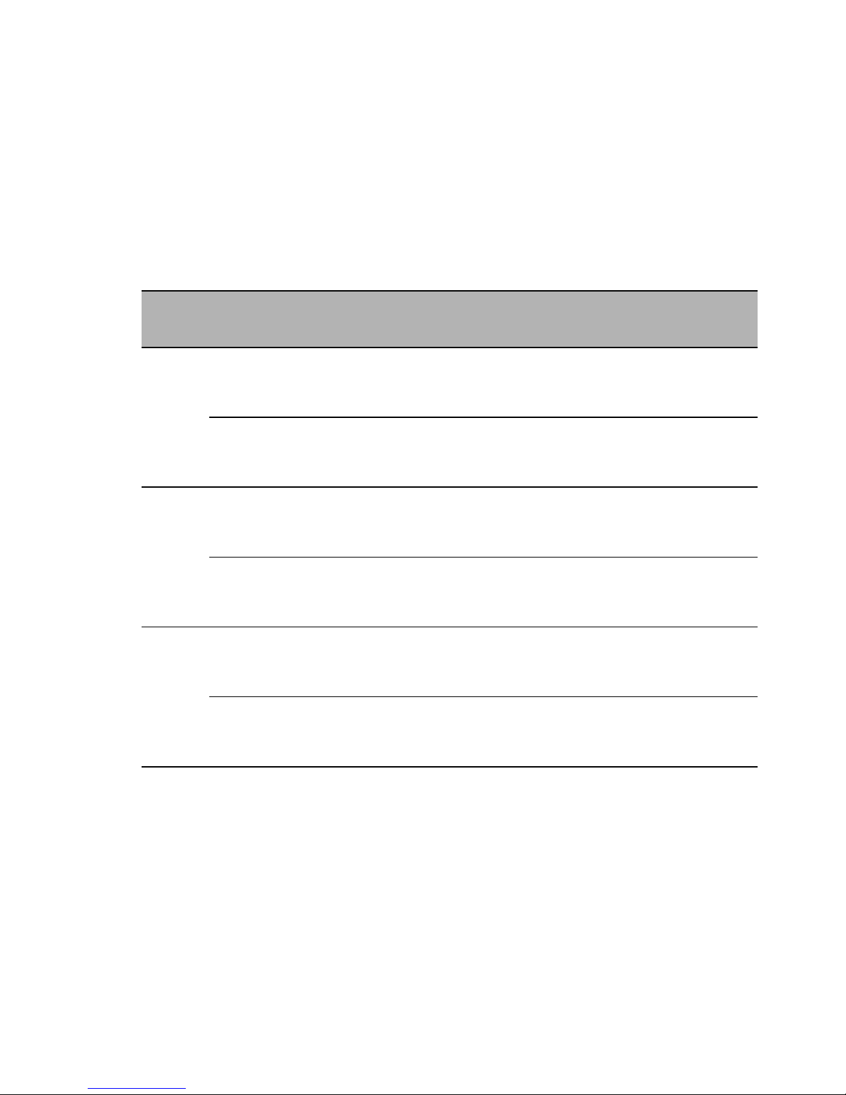
Uplink ports Other ports PoE ports included
Variant NumberType Number Type NumberType
RS20-... 2 Ports 1 and 2
10/100 Mbit/s,
media selectable,
DSC, ST, RJ45
2, 6, 14, 2210/100 Mbit/s,
TP, RJ45
——
3 Ports 1 to 3
10/100 Mbit/s,
media selectable,
DSC, ST, RJ45
6, 14, 22 10/100 Mbit/s,
TP, RJ45
——
RS22-... 2 Ports 1 and 2
10/100 Mbit/s,
media selectable,
DSC, ST, RJ45
6, 14, 22 10/100 Mbit/s,
TP, RJ45
4 10/100 Mbit/s,
TP, RJ45
3 Ports 1 to 3
10/100 Mbit/s,
media selectable,
DSC, ST, RJ45
6, 14, 22 10/100 Mbit/s,
TP, RJ45
4 10/100 Mbit/s,
TP, RJ45
RS30-... 2 Ports 1 and 2
1000 Mbit/s,
media selectable,
SFP, RJ45
8, 16, 24 10/100 Mbit/s,
TP, RJ45
——
4 Ports 1+2, 3+4
2x100/1000 Mbit/s,
2x 100 Mbit/s,
F/O, SFP
6, 14, 22 10/100 Mbit/s,
TP, RJ45
——
Table 1: Number and type of ports
Page 22

22
Installation RS20/22/30/32/40
Release 05 12/2015
RS32-... 2 Ports 1 and 2
1000 Mbit/s,
media selectable,
SFP, RJ45
8, 16, 24 10/100 Mbit/s,
TP, RJ45
4 10/100 Mbit/s,
TP, RJ45
4 Ports 1+2, 3+4
2x100/1000 Mbit/s,
2x 100 Mbit/s,
F/O, SFP
6, 14, 22 10/100 Mbit/s,
TP, RJ45
4 10/100 Mbit/s,
TP, RJ45
RS40-... 4 Ports 1 to 4
4 combo ports:
100/1000 Mbit/s,
F/O, SFP
10/100/1000 Mbit/s,
TP, RJ45
5 10/100/
1000 Mbit/s,
TP, RJ45
——
Uplink ports Other ports PoE ports included
Variant NumberType Number Type NumberType
Table 1: Number and type of ports
Page 23

Installation RS20/22/30/32/40
Release 05 12/2015
23
1.1.1 Combination options of the device variants
RS20/RS30/RS22/RS32
The product designation of your device is made from combining the desired
product characteristics in accordance with the following table. You will find
the corresponding short designation in columns 3 and 4.
Position Characteristic Ident. Ident.2 a)Property
1 to 4 Product RS20 Rail Switch without gigabit ports
RS30 Rail Switch with gigabit ports
RS22 Rail Switch without gigabit ports, with
PoE
b)c)
RS32 Rail Switch with gigabit ports, with PoE
d)e)
5 - (hyphen) 6 bis 7 Number of
10/100 Mbit/s ports
04 4 × 10/100 Mbit/s Ethernet
08 8 × 10/100 Mbit/s Ethernet
09 9 × 10/100 Mbit/s Ethernet
16 16 × 10/100 Mbit/s Ethernet
17 17 × 10/100 Mbit/s Ethernet
24 24 × 10/100 Mbit/s Ethernet
25 25 × 10/100 Mbit/s Ethernet
8 and 9 Number of
1000 Mbit/s ports
00 0 × 1000 Mbit/s Ethernet
02 2 × 1000 Mbit/s Ethernet
(not for 4-port devices)
f)
10 and 11 a)Uplink port(s)
1 port
(Ident. column)
or alternatively
2 ports
(Ident.2 column)
T1 Twisted Pair TX, RJ45
M2 MM
g)
Multimode FX, DSC, 100 Mbit/s
M4 NN
h)
Multimode FX, ST, 100 Mbit/s
S2 VV
i)
Singlemode FX, DSC, 100 Mbit/s
S4 UU
j)
Singlemode FX, ST, 100 Mbit/s
E2 EE
k)l)
Singlemode+ FX, DSC, 100 Mbit/s
L2 LL
m)
Singlemode Longhaul, DSC, 100 Mbit/s
G2 GG
n)
Singlemode Longhaul FX DSC 200 km,
100 Mbit/s
O6 OO
o)p)
SFP slot, 100q)/1000 Mbit/s
Z6 ZZ
r)s)
SFP slot, 100 Mbit/s
12 and 13 a)See items 10
and 11
14 Temperature range S Standard: +32 °F to +140 °F
(0 °C to +60 °C)
t)
T Extended −40 °F to +158 °F
(−40 °C to +70 °C )
u)v)
E Extended −40 °F to +158 °F
(−40 °C to +70 °C ),
Conformal Coating
w)x)y)
Voltage range incl.
maximum
tolerances
D
z)
9.6 V DC to 60 V DC or
18 V AC to 30 V AC
P
aa)
47 V DC to 52 V DC (PoE)
Table 2: Combination options of the device variants RS20/RS30/RS22/RS32
Page 24

24
Installation RS20/22/30/32/40
Release 05 12/2015
16 Approval A CE, UL 508, ISA 12.12.01 (UL 1604)
H CE, UL 508, ISA 12.12.01 (UL 1604), GL,
Railway (along track), Sub Station
B
ab)
CE, UL 508, ISA 12.12.01 (UL 1604), GL,
Railway (along track), Sub Station,
Hazardous Location/ATEX/IECEx
17 Software variant E Enhanced
P Professional
a. For device variants with 2 uplink ports you use the “Ident.” column for items 10+11 and for
items 12+13.
For device variants with 3 uplink ports you use the “Ident.2” column for items 10+11 and the
“Ident.” column for items 12+13.
For device variants with 4 uplink ports you use the “Ident.2” column for items 10+11 and for
items 12+13.
b. Not in combination with “04×100 Mbit/s Ethernet”.
c. The last 4 ports of the device have PoE (Power over Ethernet).
d. Not in combination with “04×100 Mbit/s Ethernet”.
e. The last 4 ports of the device have PoE (Power over Ethernet).
f. Not in combination with “04×100 Mbit/s Ethernet”.
g. For RS20-0900..., RS20-1700..., RS20-2500...;
RS22-0900..., RS22-1700..., RS22-2500...
h. For RS20-0900..., RS20-1700..., RS20-2500...;
RS22-0900..., RS22-1700..., RS22-2500...
i. For RS20-0900..., RS20-1700..., RS20-2500...;
RS22-0900..., RS22-1700..., RS22-2500...
j. For RS20-0900..., RS20-1700..., RS20-2500...;
RS22-0900..., RS22-1700..., RS22-2500...
k. For RS20-0900..., RS20-1700..., RS20-2500...;
RS22-0900..., RS22-1700..., RS22-2500...
l. Devices with ports with product code E2 or EE: only certification “A” available (see product
code for item16).
m. For RS20-0900..., RS20-1700..., RS20-2500...;
RS22-0900..., RS22-1700..., RS22-2500...
n. For RS20-0900..., RS20-1700..., RS20-2500...;
RS22-0900..., RS22-1700..., RS22-2500...
o. Not in combination with “04×100 Mbit/s Ethernet”.
p. In connection with “2nd uplink port” “ZZ” and “1st uplink port” “OO”.
q. Only for “OO” combination
r. In combination with “2nd uplink port” “ZZ” and “1st uplink port” “OO”.
s. Not in combination with “04×100 Mbit/s Ethernet”.
t. With a UL-508, ATEX/IECEx, or ISA 12.12.01 certification, the maximum operating
temperature for the standard ‘S’ temperature range for PoE-capable devices (RS22-...,
RS32-...) is +122 °F (+50 °C).
u. The extended ‘E’ temperature range for the PoE-capable devices is −40 °F to +140 °F
(−40 °C to +60 °C).
With a UL-508, ATEX/IECEx, or ISA 12.12.01 approval, the maximum operating
temperature for the extended ‘E’ temperature range for PoE-capable devices (RS22-...,
RS32-...) is +122 °F (+50 °C).
v. Not when using GG or G2 transceivers.
w. The extended ‘T’ temperature range for the PoE-capable devices is −40 °F to +140 °F
(−40 °C to +60 °C).
With a UL-508, ATEX/IECEx, or ISA 12.12.01 approval, the maximum operating
temperature for the extended ‘T’ temperature range for PoE-capable devices (RS22-...,
RS32-...) is +122 °F (+50 °C).
x. Not when using GG or G2 transceivers.
y. In combination with “2nd uplink port” “ZZ” and “1st uplink port” “OO”.
z. Not for PoE-capable devices (RS22-..., RS32-...).
aa. For PoE-capable devices (RS22-..., RS32-...).
ab. Without railway approval EN 50155 (Train).
Position Characteristic Ident. Ident.2 a)Property
Table 2: Combination options of the device variants RS20/RS30/RS22/RS32
Page 25

Installation RS20/22/30/32/40
Release 05 12/2015
25
Examples for product name
Additional examples of devices with 3 or 4 uplink ports:
RS20-0900NNM4TDAE for RS20 with 3 uplink ports (ST)
NN: 2 × Multimode FX, ST, 100 Mbit/s (ports 1 and 2)
M4: 1 × Multimode FX, ST, 100 Mbit/s (port 3)
RS30-2402OOZZTDAP for RS30 with 4 uplink ports (SFP)
OO: 2 × SFP slot, 1000 Mbit/s (ports 1 and 2)
ZZ: 2 × SFP slot, 100 Mbit/s (ports 3 und 4)
Example of device with Power over Ethernet:
RS32-0802O6T1SPAP for RS32 with 2 uplink ports and PoE
O6: 1 × SFP slot, 1000 Mbit/s (port 1)
T1: 1 × twisted pair TX, RJ45, 1000 Mbit/s (port 2)
P: Voltage range 47 V DC to 52 V DC (PoE)
RS20-
RS20- Rail Switch without gigabit ports
09
09 9 × 100 Mbit/s Ethernet ports
00
00 0 × 100 Mbit/s Ethernet ports
MM
MM Port 1 + 2 = 2 × Multimode FX, DSC, 100 Mbit/s
M2
M2 Port 3 = Multimode FX, DSC, 100 Mbit/s
S
S Temperature range: Standard: +32 °F ... +140 °F (0 °C ... +60 °C)
D
D Voltage range: 9.6 V DC to 60 V DC or 18 V AC to 30 V AC
A
A Approvals: CE, UL 508, ISA 12.12.01 (UL 1604)
P
P Software variant: Professional
Table 3: Example of RS20 with 3 uplink ports: RS20-0900MMM2SDAP
RS30-
RS30- Rail Switch with gigabit ports
08
08 8 × 100 Mbit/s Ethernet ports
02
02 2 × 100 Mbit/s Ethernet ports
O6
O6 Port 1 = SFP slot, 1000 Mbit/s
T1
T1 Port 2 = twisted pair TX, RJ45 connector, 1000 Mbit/s
T
T Temperature range Extended −40 °F to +158 °F (−40 °C to +70 °C )
D
D Voltage range: 9.6 V DC to 60 V DC or 18 V AC to 30 V AC
A
A Approvals: CE, UL 508, ISA 12.12.01 (UL 1604)
E
E Software variant: Enhanced
Table 4: Example of RS30 with 2 uplink ports: RS30-0802O6T1TDAE
Page 26

26
Installation RS20/22/30/32/40
Release 05 12/2015
1.1.2 Combination options for the RS40 device variants
The product designation of your device is made from combining the desired
product characteristics in accordance with the following table. The
corresponding short designation is in column 3.
Position Characteristic Ident. Property
1 to 4 Product RS40 Rail Switch with gigabit ports
5 - (hyphen) 6 to 7 Number of 10/100
Mbit/s ports
00 0 × 10/100 Mbit/s Ethernet
8 and 9 Number of 1000
Mbit/s ports
09 9 × 1000 Mbit/s Ethernet
10 and 11 1. + 2. Uplink port CC 2 × Combo port multirate (SFP slot:
100/1000 Mbit/s; alternatively twisted pair RJ45
socket: 10/100/1000 Mbit/s)
12 and 13 3. + 4. Uplink port CC 2 × Combo Port multirate (SFP-slot:
100/1000 Mbit/s; alternatively twisted pair RJ45
socket: 10/100/1000 Mbit/s)
14 Temperature range S Standard: +32 °F to +140 °F (0 °C to +60 °C)
T Extended: -40 °F to + 158 °F (−40 °C to +70 °C)
E Extended: −40 °F to + 158 °F (−40 °C to +70 °C),
Conformal Coating
15 Voltage range D 9.6 V DC to 60 V DC or
18 V AC to 30 V AC
16 Approval A CE, UL 508, ISA 12.12.01 (UL 1604)
H CE, UL 508, GL, Railway (along track), Sub station,
ISA 12.12.01 (UL 1604)
B CE, UL 508, GL, Railway (along track), Sub station,
ISA 12.12.01 (UL 1604), Hazardous
Location/ATEX/IECEx
17 Software variant E Enhanced
P Professional
Table 5: Combination options for the RS40 device variants
Page 27
Installation RS20/22/30/32/40
Release 05 12/2015
27
Examples for product name
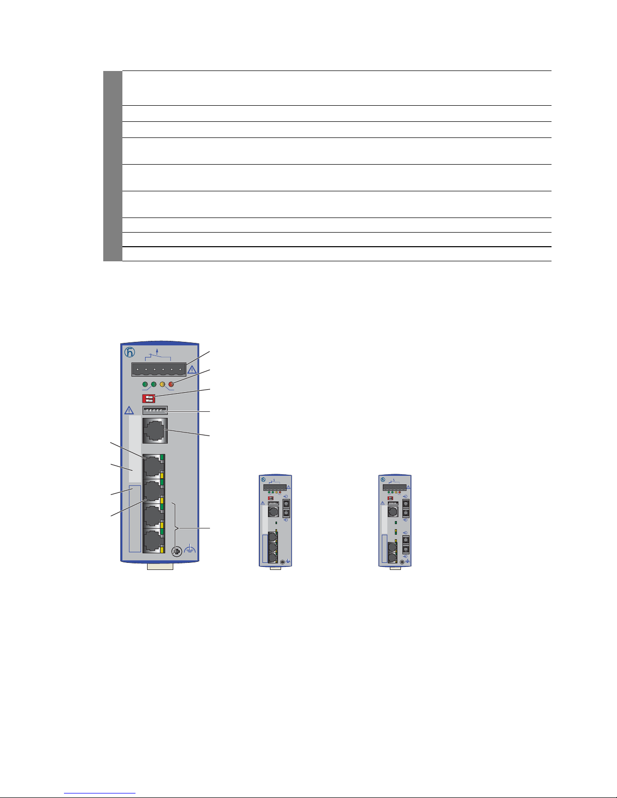
1.1.3 Number of ports and media for RS20-...
Figure 1: Device variants with 4 × 10/100 Mbit/s ports (RS20-0400...)
1 – plug-in terminal block, 6-pin
2 – LED display elements
3 – 2-pin DIP switch
4 – USB interface
5 – V.24 connection for external management
6 – ports in compliance with 10/100BASE-T(X) (RJ45 connections)
7 – port 1 + port 2, free choice of connections:
T1: Twisted-pair T(X), RJ45, 10/100 Mbit/s
RS40-
RS40- Rail Switch with gigabit ports
00
00 0 × 100 Mbit/s Ethernet ports
09
09 9 × 1000 Mbit/s Ethernet ports
CC
CC Port 1 + 2 = Combo port: SFP slot (100/1000 Mbit/s),
alternatively: RJ45 connector (10/100/1000 Mbit/s)
CC
CC Port 3 + 4 = Combo port: SFP slot (100/1000 Mbit/s),
alternatively: RJ45 connector (10/100/1000 Mbit/s)
E
E Temperature range Extended (−40 °F to +158 °F; −40 °C to +70 °C )
with Conformal Coating
D
D Voltage range: 9.6 V DC to 60 V DC or 18 V AC to 30 V AC
A
A Approvals: CE, UL 508, ISA 12.12.01 (UL 1604)
P
P Software variant: Professional
Table 6: Example of RS40 with 4 uplink ports: RS40-0009CCCCEDAP
RS20
RM
Stand by
Aufkleber MAC-Adresse
IP-ADDRESS
V.24
USB
P
Stand by
FAULT
RM
ON
LS
1
DA
LS
2
DA
LS
3
DA
LS
4
DA
1
2
3
4
5
6
7
7
8
9
RS20-0400T1T1...D... RS20-0400M2T1...D...
RS20
RM
Stand by
Aufkleber MAC-Adresse
IP-ADDRESS
V.24
USB
P
Stand by
FAULT
RM
ON
1
LS
2
DA
LS
3
DA
LS
4
DA
RS20
RM
Stand by
Aufkleber MAC-Adresse
IP-ADDRESS
V.24
USB
P
Stand by
FAULT
RM
ON
1
2
LS
3
DA
LS
4
DA
RS20-0400M2M2...D...
LS
1
DA
LS
2
DA
LS
1
DA
+24V(P1) 0V 0V
FAULT
+24V(P2)
+24V(P1) 0V 0V
FAULT
+24V(P2) +24V(P1) 0V 0V
FAULT
+24V(P2)
Page 28
28
Installation RS20/22/30/32/40
Release 05 12/2015
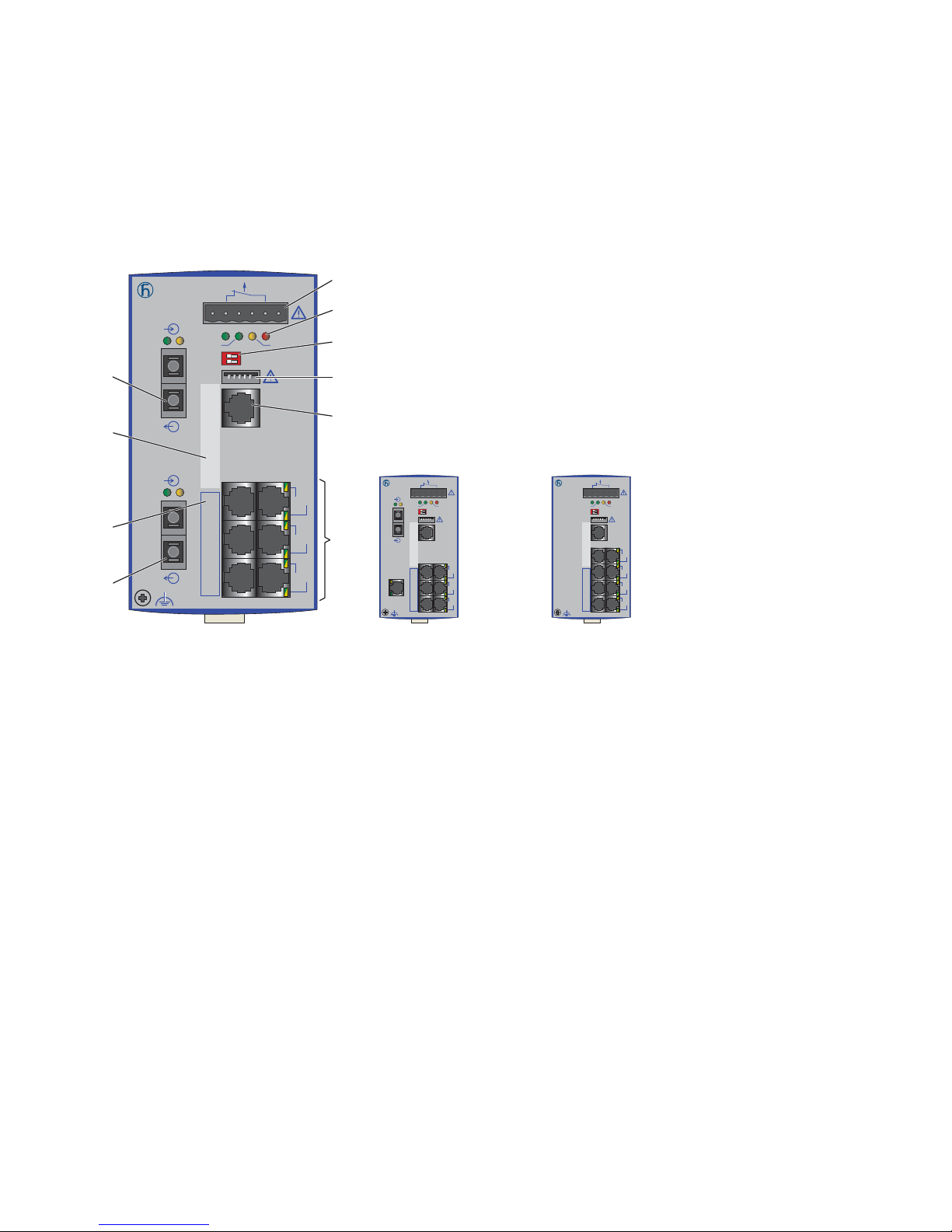
M2: Multimode FX, DSC, 100 Mbit/s
M4: Multimode FX, ST, 100 Mbit/s
S2: Singlemode FX, DSC, 100 Mbit/s
S4: Singlemode FX, ST, 100 Mbit/s
L2: Singlemode Longhaul FX, DSC, 100 Mbit/s
G2: Singlemode Longhaul+ FX, DSC, 100 Mbit/s, 200 km
8 – MAC address field
9 – IP address field
Figure 2: Device variants with 8 × 10/100 Mbit/s ports (RS20-0800...)
1 to 9 – see figure 1
RS20
LS DA
RM
+24V(P1) 0V 0V
FAULT
+24V(P2)
Sta nd by
Aufkleber MAC-Adresse
IP-ADDRESS
2
LS DA
1
3
5
7
4
6
8
V.2 4
USB
P
Sta nd by
FAULT
RM
ON
1
2
3
4
5
6
7
8
9
7
RS20-0800M2M2...D...
RS20
RM
+24V(P1) 0V 0V
FAULT
+24V(P2)
Stand by
Aufkleber MAC-Adresse
IP-ADDRESS
1
3
5
7
2
4
6
8
V.24
USB
P
Stand by
FAULT
RM
ON
RS20-0800T1T1...D...
RS20
RM
+24V(P1) 0V 0V
FAULT
+24V(P2)
Stand by
Aufkleber MAC-Adresse
IP-ADDRESS
LS DA
1
3
5
7
4
6
8
V.24
USB
P
Stand by
FAULT
RM
ON
DA
2
LS
RS20-0800M2T1...D...
Page 29
Installation RS20/22/30/32/40
Release 05 12/2015
29
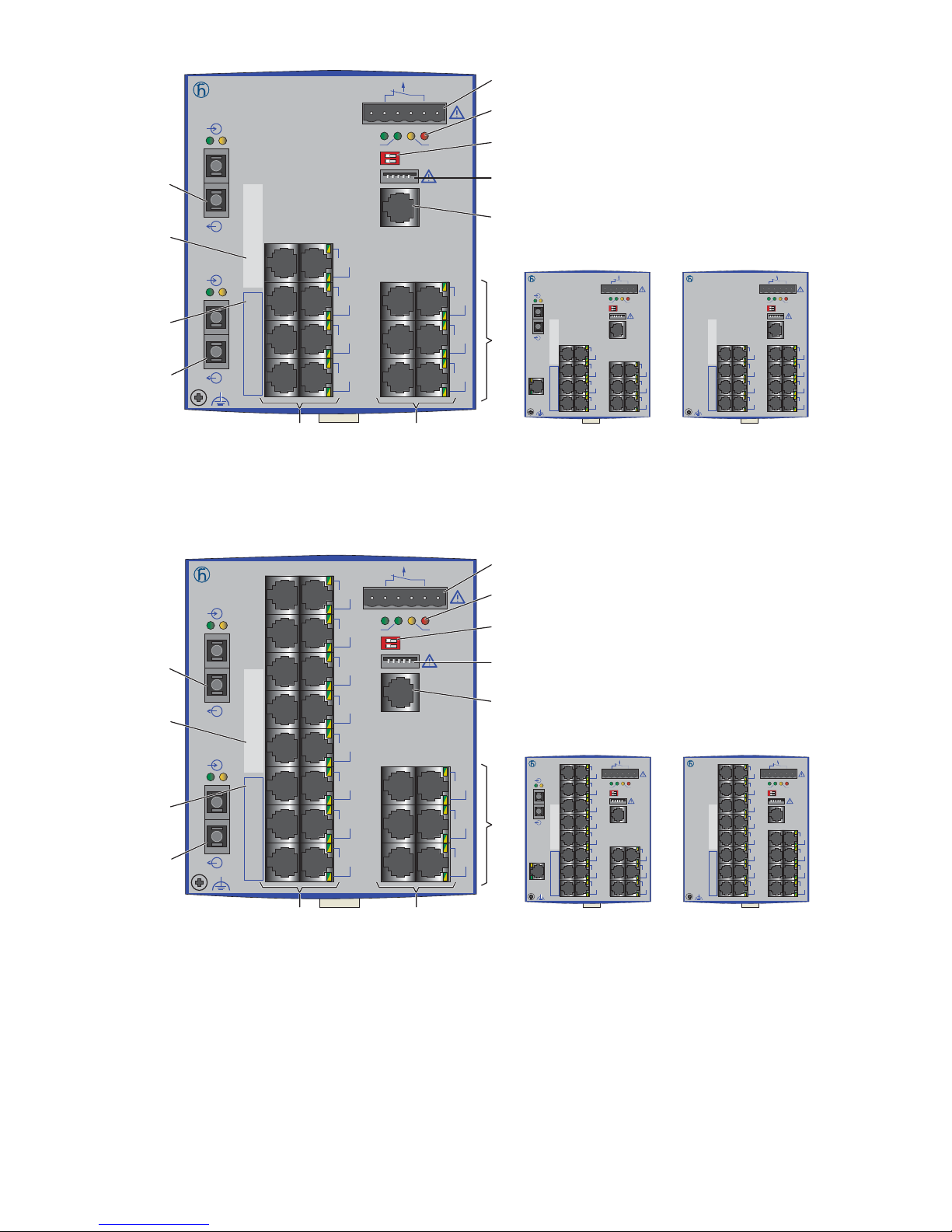
Figure 3: Device variants with 16 × 10/100 Mbit/s ports (RS20-1600...)
1 to 9 – see figure 1
Figure 4: Device variants with 24 × 10/100 Mbit/s ports (RS20-2400...)
1 to 9 – see figure 1
RS20
LS DA
RM
+24V(P1) 0V 0V
FAULT
+24V(P2)
Sta nd by
Aufkleber MAC-Adresse
IP-ADDRESS
2
LS DA
1
V.2 4
USB
P
Sta nd by
FAULT
RM
ON
3
5
7
9
4
6
8
10
11
13
15
12
14
16
RS20
RM
+24V(P1) 0V 0V
FAULT
+24V(P2)
Stand by
Aufkleber MAC-Adresse
IP-ADDRESS
LS DA
1
V.24
USB
P
Stand by
FAULT
RM
ON
3
5
7
9
4
6
8
10
11
13
15
12
14
16
2
DA
LS
1
2
3
4
5
6
66
7
8
9
7
RS20-1600M2M2...D...
RS20
RM
+24V(P1) 0V 0V
FAULT
+24V(P2)
Stand by
Aufkleber MAC-Adresse
IP-ADDRESS
1
3
5
7
2
4
6
8
9
11
13
15
10
12
14
16
V.24
USB
P
Stand by
FAULT
RM
ON
RS20-1600T1T1...D...
RS20-1600M2T1...D...
RS20
LS DA
RM
+24V(P1) 0V 0V
FAULT
+24V(P2)
Sta nd by
Aufkleber MAC-Adresse
IP-ADDRESS
3
5
7
9
11
13
15
17
2
LS DA
1
4
6
8
10
12
14
16
18
19
21
23
20
22
24
V.2 4
USB
P
Sta nd by
FAULT
RM
ON
RS20
RM
+24V(P1) 0V 0V
FAULT
+24V(P2)
Stand by
Aufkleber MAC-Adresse
IP-ADDRESS
3
5
7
9
11
13
15
17
4
6
8
10
12
14
16
18
19
21
23
20
22
24
V.24
USB
P
Stand by
FAULT
RM
ON
LS DA
1
2
DA
LS
RS20
RM
+24V(P1) 0V 0V
FAULT
+24V(P2)
Stand by
Aufkleber MAC-Adresse
IP-ADDRESS
1
3
5
7
9
11
13
15
2
4
6
8
10
12
14
16
17
19
21
23
18
20
22
24
V.24
USB
P
Stand by
FAULT
RM
ON
1
2
3
4
5
6
66
7
8
9
7
RS20-2400M2M2...D...
RS20-2400M2T1...D... RS20-2400T1T1...D...
Page 30
30
Installation RS20/22/30/32/40
Release 05 12/2015
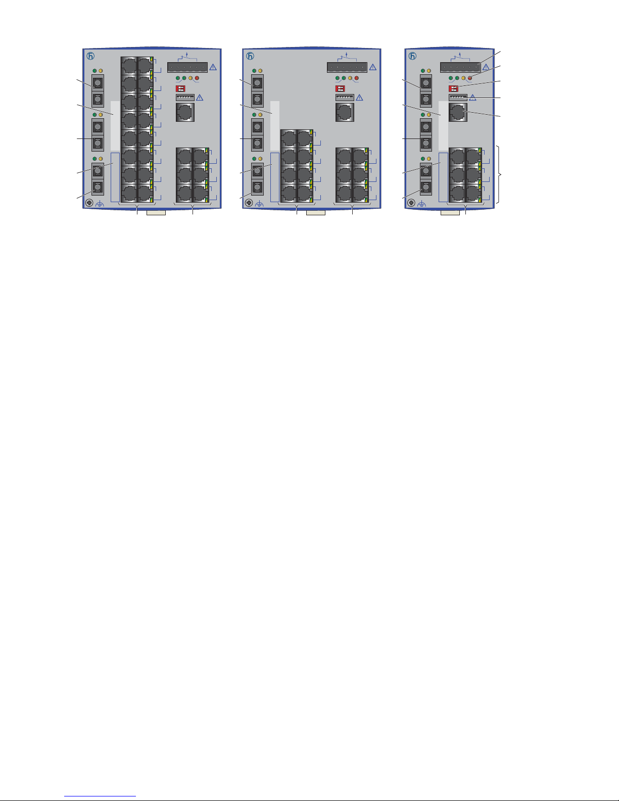
Figure 5: Device variants with 3 uplink ports (100 Mbit/s)
1 to 6 – see figure 1
7 – port 3, free choice of connection:
T1: Twisted-pair T(X), RJ45, 10/100 Mbit/s
M2: Multimode FX, DSC, 100 Mbit/s
M4: Multimode FX, ST, 100 Mbit/s
S2: Singlemode FX, DSC, 100 Mbit/s
S4: Singlemode FX, ST, 100 Mbit/s
L2: Singlemode Longhaul FX, DSC, 100 Mbit/s
G2: Singlemode Longhaul+ FX, DSC, 100 Mbit/s, 200 km
8 – MAC address field
9 – port 1 + port 2, free choice of connections:
MM: Multimode FX, DSC, 100 Mbit/s
NN: Multimode FX, ST, 100 Mbit/s
VV: Singlemode FX, DSC, 100 Mbit/s
UU: Singlemode FX, ST, 100 Mbit/s
LL: Singlemode Longhaul FX, DSC, 100 Mbit/s
GG: Singlemode Longhaul+ FX, DSC, 100 Mbit/s, 200 km
10 – IP address field
RS20
+24V(P1) 0V 0V
FAULT
+24V(P2)
4
6
8
10
12
14
16
18
5
7
9
11
13
15
17
19
20
22
24
21
23
25
RS20
+24V(P1) 0V 0V
FAULT
+24V(P2)
4
6
8
10
5
7
9
11
12
14
16
13
15
17
RS20
+24V(P1) 0V 0V
FAULT
+24V(P2)
4
6
8
5
7
9
LS DA
2
LS DA
1
LS DA
3
LS DA
2
LS DA
1
LS DA
3
LS DA
2
LS DA
1
LS DA
3
RM
Stand by
Aufkleber MAC-Adresse
IP-ADDRESS
V.24
USB
P
Stand by
FAULT
RM
ON
RM
Stand by
Aufkleber MAC-Adresse
IP-ADDRESS
V.24
USB
P
Stand by
FAULT
RM
ON
RM
Stand by
Aufkleber MAC-Adresse
IP-ADDRESS
V.24
USB
P
Stand by
FAULT
RM
ON
1
2
3
4
5
6
66666
7
9
8
10
9
7
9
8
10
9
7
9
8
10
9
RS20-2500MMM2...D... RS20-1700MMM2...D...
RS20-0900MMM2...D...
Page 31
Installation RS20/22/30/32/40
Release 05 12/2015
31
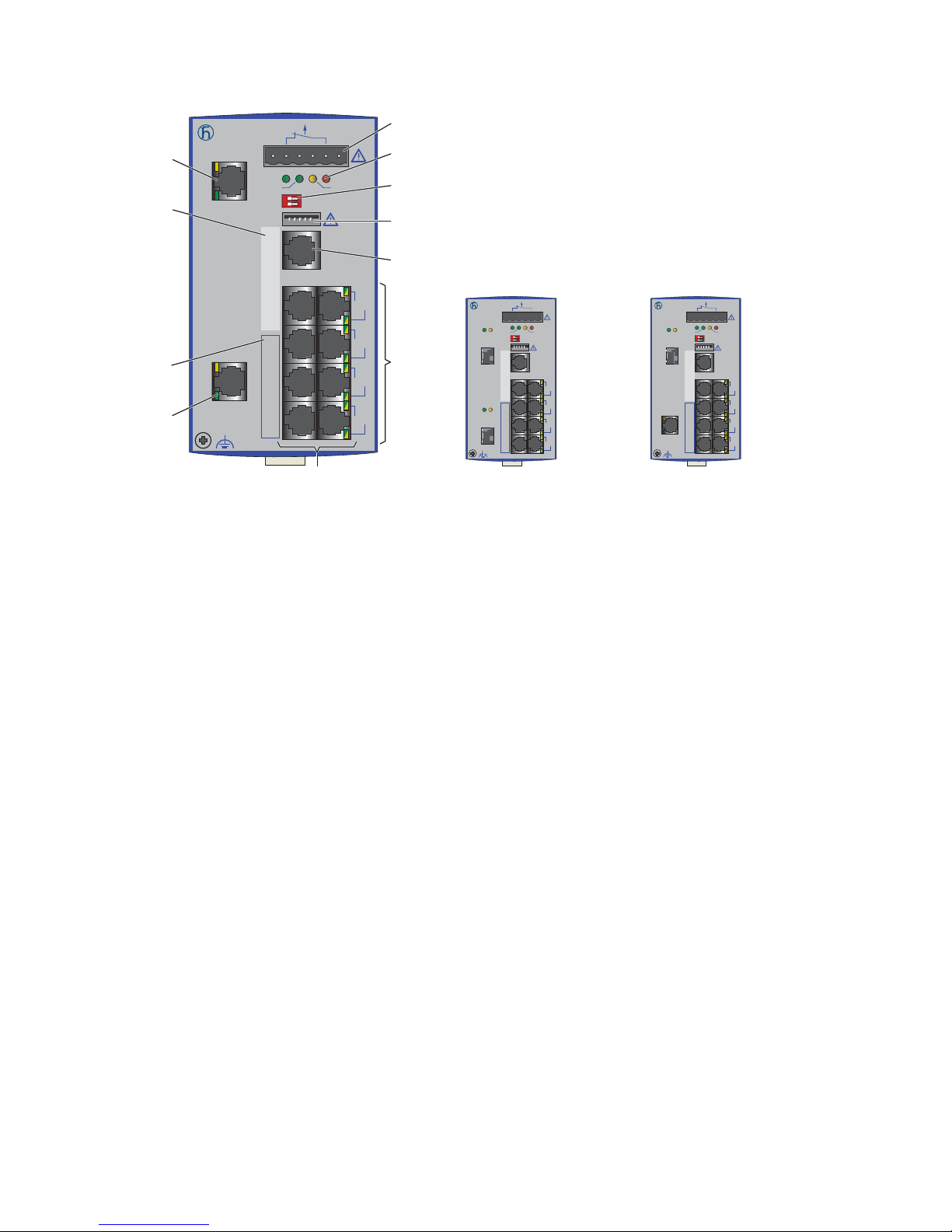
1.1.4 Number of ports and media for RS30-...
Figure 6: Device variants with 2 × 1000 Mbit/s ports and 8 × 10/100 Mbit/s ports
(RS30-0802...)
1 – plug-in terminal block, 6-pin
2 – LED display elements
3 – 2-pin DIP switch
4 – USB interface
5 – V.24 connection for external management
6 – ports in compliance with 10/100BASE-T(X) (RJ45 connections)
7 – port 1 + port 2, free choice of connections:
T1: Twisted-pair T(X), RJ45, 10/100/1000 Mbit/s
O6: SX/LX, SFP slot, 1000 Mbit/s
8 – MAC address field
9 – IP address field
RS30
RM
+24V(P1) 0V 0V
FAULT
+24V(P2)
Sta nd by
Aufkleber MAC-Adresse
IP-ADDRESS
3
5
7
9
4
6
8
10
V.2 4
USB
P
Sta nd by
FAULT
RM
ON
DA
2
LS
DA
1
LS
RS30
RM
+24V(P1) 0V 0V
FAULT
+24V(P2)
Stand by
Aufkleber MAC-Adresse
IP-ADDRESS
LS DA
1
V.24
USB
P
Stand by
FAULT
RM
ON
DA
2
LS
3
5
7
9
4
6
8
10
RS30
RM
+24V(P1) 0V 0V
FAULT
+24V(P2)
Stand by
Aufkleber MAC-Adresse
IP-ADDRESS
V.24
USB
P
Stand by
FAULT
RM
ON
LS DA
1
LS DA
2
3
5
7
9
4
6
8
10
1
2
3
4
5
6
6
7
8
9
7
RS30-0802T1T1...D...
RS30-0802O6T1...D...RS30-0802O6O6...D...
Page 32
32
Installation RS20/22/30/32/40
Release 05 12/2015
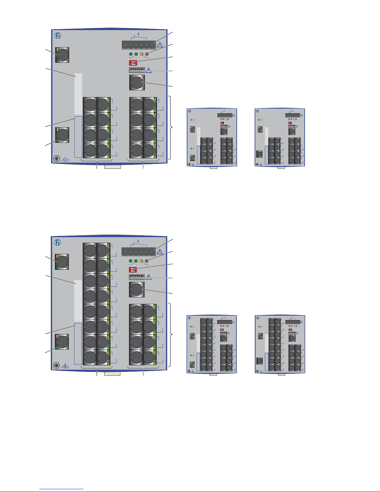
Figure 7: Device variants with 2 × 1000 Mbit/s ports and 16 × 10/100 Mbit/s ports
(RS30-1602...)
1 to 9 – see figure 6
Figure 8: Device variants with 2 × 1000 Mbit/s ports and 24 × 10/100 Mbit/s ports
(RS30-2402...)
1 to 9 – see figure 6
RS30
RM
+24V(P1) 0V 0V
FAULT
+24V(P2)
Sta nd by
Aufkleber MAC-Adresse
IP-ADDRESS
3
5
7
9
4
6
8
10
11
13
15
17
12
14
16
18
V.2 4
USB
P
Sta nd by
FAULT
RM
ON
2
DA
LS
1
DA
LS
RS30
RM
+24V(P1) 0V 0V
FAULT
+24V(P2)
Stand by
Aufkleber MAC-Adresse
IP-ADDRESS
V.24
USB
P
Stand by
FAULT
RM
ON
3
5
7
9
4
6
8
10
11
13
15
17
12
14
16
18
LS DA
1
2
DA
LS
RS30
RM
+24V(P1) 0V 0V
FAULT
+24V(P2)
Stand by
Aufkleber MAC-Adresse
IP-ADDRESS
V.24
USB
P
Stand by
FAULT
RM
ON
3
5
7
9
4
6
8
10
11
13
15
17
12
14
16
18
LS DA
1
LS DA
2
RS30-1602T1T1...D...
RS30-1602O6O6...D... RS30-1602O6T1...D...
1
2
3
4
5
6
66
7
8
9
7
RS30
RM
+24V(P1) 0V 0V
FAULT
+24V(P2)
Sta nd by
Aufkleber MAC-Adresse
IP-ADDRESS
3
5
7
9
11
13
15
17
4
6
8
10
12
14
16
18
19
21
23
25
20
22
24
26
V.2 4
USB
P
Sta nd by
FAULT
RM
ON
2
DA
LS
1
DA
LS
RS30
RM
+24V(P1) 0V 0V
FAULT
+24V(P2)
Stand by
Aufkleber MAC-Adresse
IP-ADDRESS
V.24
USB
P
Stand by
FAULT
RM
ON
3
5
7
9
11
13
15
17
4
6
8
10
12
14
16
18
19
21
23
25
20
22
24
26
LS DA
1
2
DA
LS
RS30
RM
+24V(P1) 0V 0V
FAULT
+24V(P2)
Stand by
Aufkleber MAC-Adresse
IP-ADDRESS
V.24
USB
P
Stand by
FAULT
RM
ON
3
5
7
9
11
13
15
17
4
6
8
10
12
14
16
18
19
21
23
25
20
22
24
26
LS DA
1
LS DA
2
1
2
3
4
5
6
66
7
8
9
7
RS30-2402T1T1...D...
RS30-2402O6T1...D...RS30-2402O6O6...D...
Page 33
Installation RS20/22/30/32/40
Release 05 12/2015
33
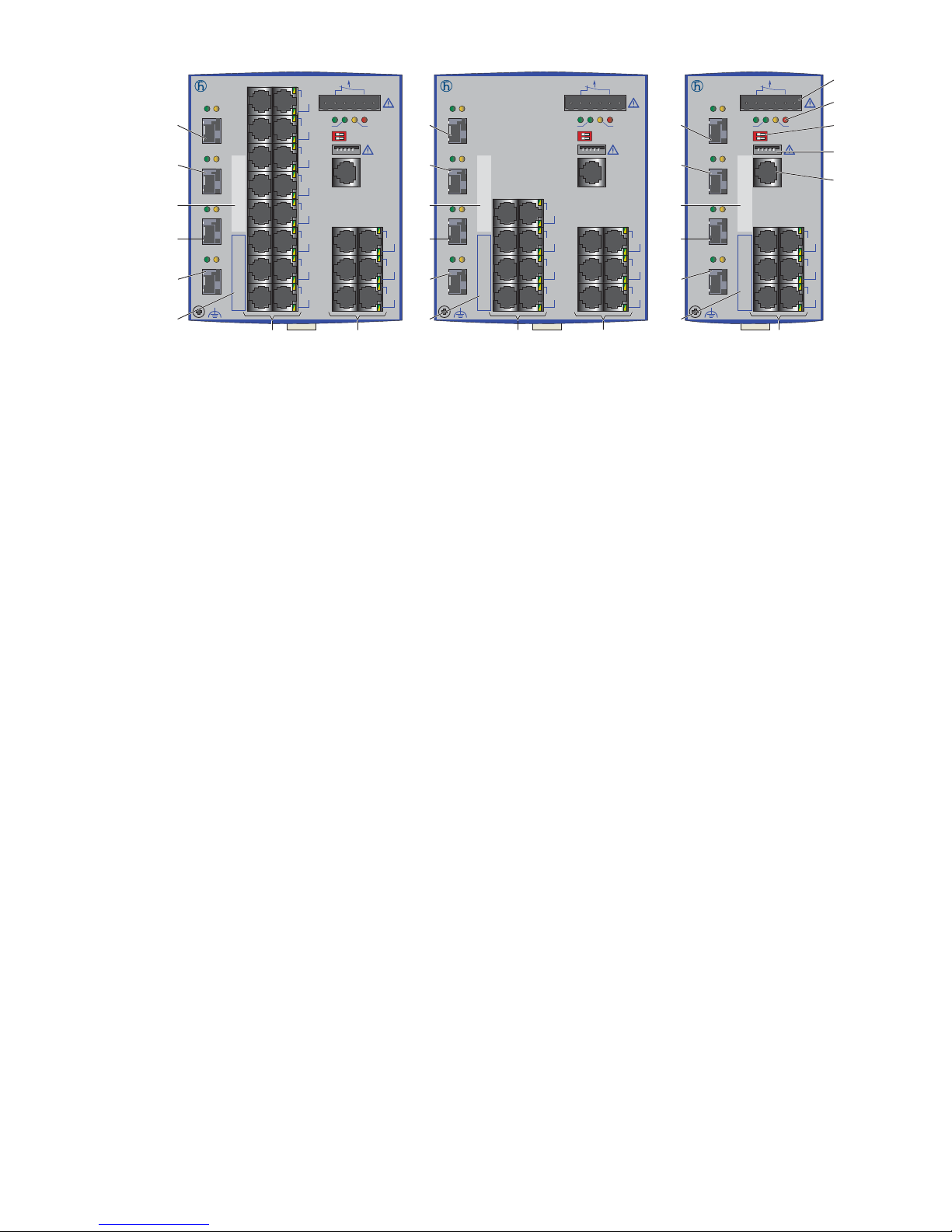
Figure 9: Device variants with 4 uplink ports
1 to 6 – see figure 6
7 – MAC address field
8 – port 3 + port 4:
ZZ: FX, SFP slot, 100 Mbit/s
9 – IP address field
10 – port 1 + port 2:
OO: FX/SX/LX, SFP slot, 100/1000 Mbit/s
RS30
+24V(P1) 0V 0V
FAULT
+24V(P2)
5
7
9
11
13
15
17
19
6
8
10
12
14
16
18
20
21
23
25
22
24
26
RS30
+24V(P1) 0V 0V
FAULT
+24V(P2)
5
7
9
11
6
8
10
12
13
15
17
14
16
18
RS30
+24V(P1) 0V 0V
FAULT
+24V(P2)
5
7
9
6
8
10
LS DA
1
LS DA
2
LS DA
3
LS DA
4
LS DA
1
LS DA
2
LS DA
3
LS DA
4
LS DA
1
LS DA
2
LS DA
3
LS DA
4
RM
Stand by
Aufkleber MAC-Adresse
IP-ADDRESS
V.24
USB
P
Stand by
FAULT
RM
ON
RM
Stand by
Aufkleber MAC-Adresse
IP-ADDRESS
V.24
USB
P
Stand by
FAULT
RM
ON
RM
Stand by
Aufkleber MAC-Adresse
IP-ADDRESS
V.24
USB
P
Stand by
FAULT
RM
ON
1
2
3
4
5
66666
7
8
8
9
10
10
7
8
8
9
10
10
7
8
8
9
10
10
RS30-2402OOZZ...D... RS30-1602OOZZ...D... RS30-0802OOZZ...D...
Page 34
34
Installation RS20/22/30/32/40
Release 05 12/2015
1.1.5 Number of ports and media for RS40-...
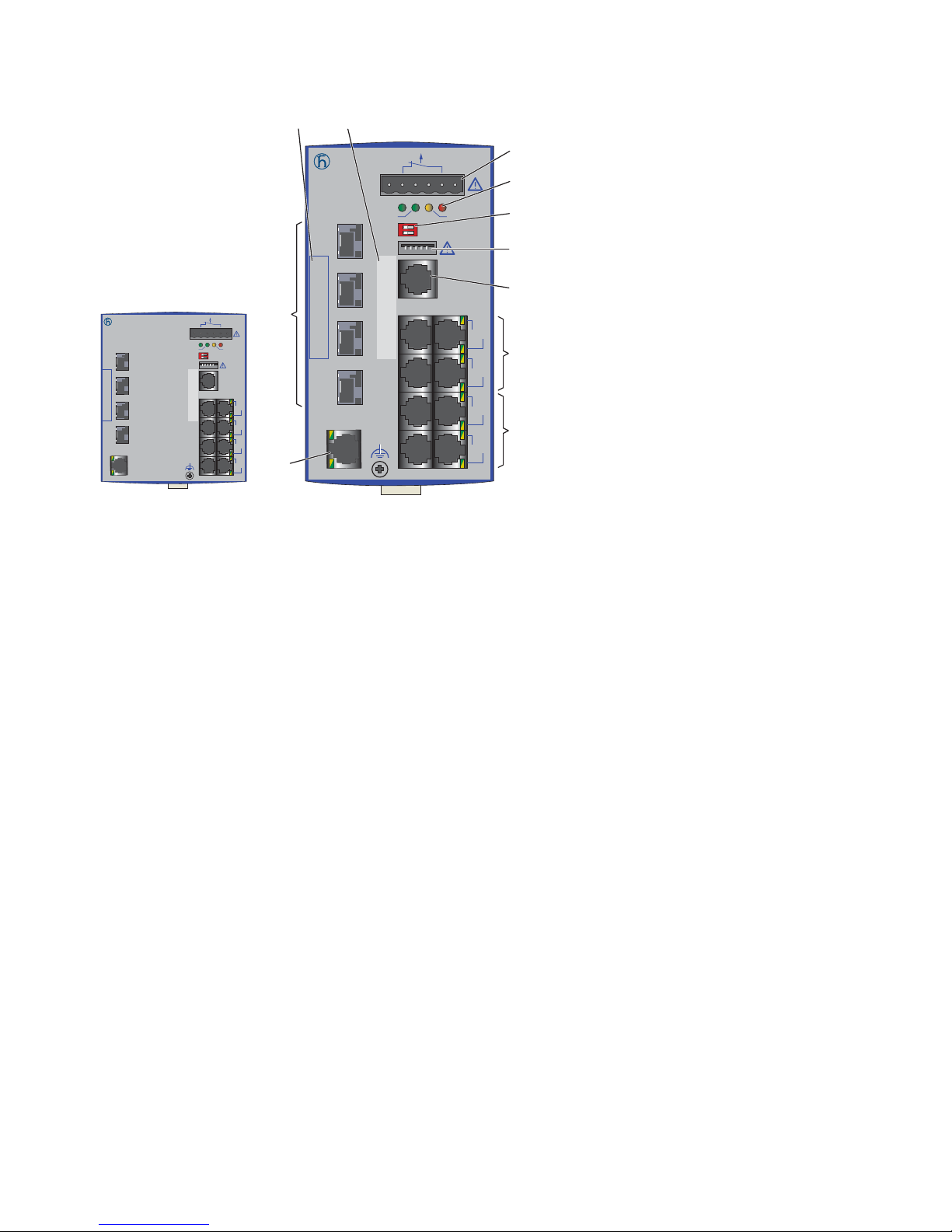
Figure 10: Device variants with 9 × 1000 Mbit/s ports (RS40-0009...)
1 to 5 and 8 to 9 – see figure 6
6 – port 1 to port 4: combo ports (CC):
FX/SX/LX, SFP slot, 100 or 1000 Mbit/s
Alternatively: T(X), RJ45 connections, 10/100/1000 Mbit/s
7 – ports in compliance with 10/100/1000BASE-T(X) (RJ45 connections)
RS40
+24V(P1) 0V 0V
FAULT
+24V(P2)
1
3
5
7
2
4
6
8
1
2
3
4
RM
Stand by
Aufkleber MAC-Adresse
IP-ADDRESS
V.24
USB
P
Stand by
FAULT
RM
ON
9
1
2
3
4
5
6
7
7
6
89
RS40-0009CCCCSD...
RS40
+24V(P1) 0V 0V
FAULT
+24V(P2)
1
3
5
7
2
4
6
8
1
2
3
4
RM
Stand by
Aufkleber MAC-Adresse
IP-ADDRESS
V.24
USB
P
Stand by
FAULT
RM
ON
9
RS40-0009CCCCED...
RS40-0009CCCCTD...
Page 35
Installation RS20/22/30/32/40
Release 05 12/2015
35
1.2 Device variants with PoE (optional)
1.2.1 Number of ports and media for devices with PoE
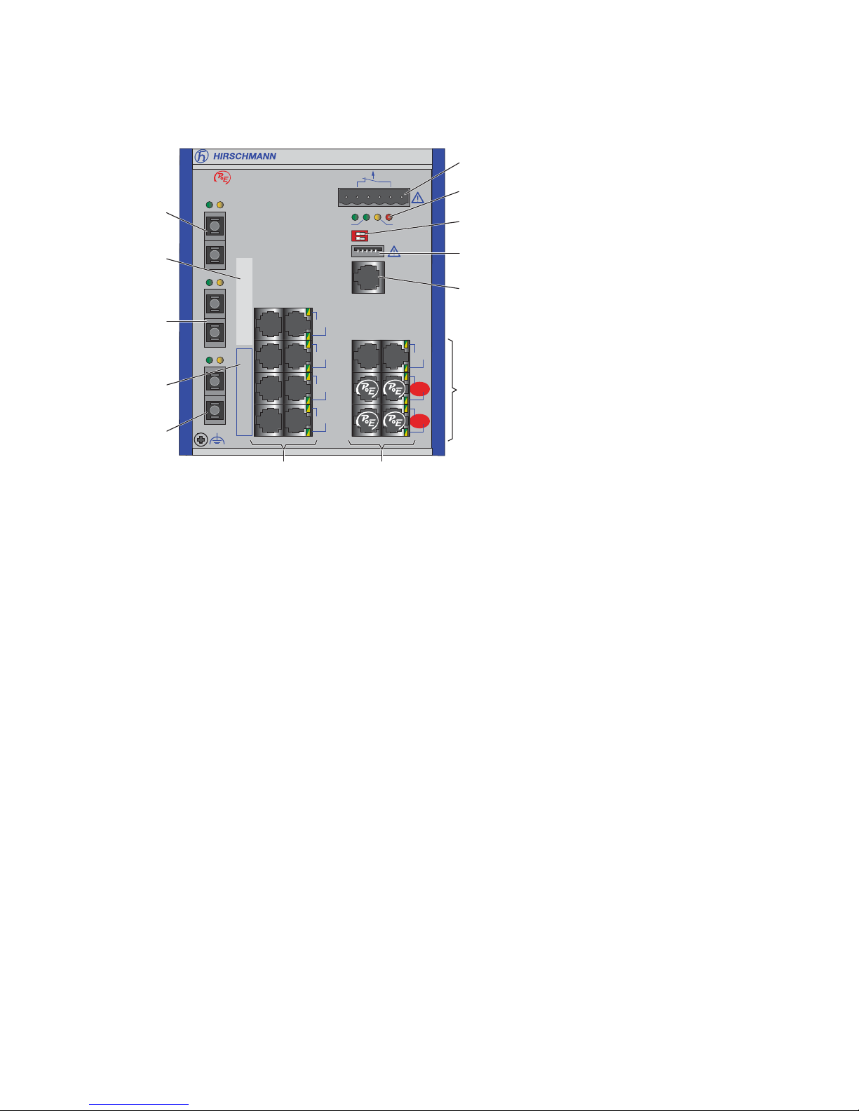
Figure 11: RS22 device variants with PoE (example: RS22-1700MMM2...P...)
1 to 5 and 7 to 9 – see figure 5
6 – ports in compliance with 10/100BASE-T(X) (RJ45 connections; the
PoE-capable ports 14 to 17 are indicated accordingly)
RS22
RM
Stand by
Aufkleber MAC-Adresse
IP-ADDRESS
V.24
USB
P
Stand by
FAULT
RM
ON
1
2
3
4
5
6
66
LS DA
2
LS DA
1
LS DA
3
7
9
8
10
9
4
6
8
10
5
7
9
11
12
14
16
13
15
17
RS22-1700MMM2...P...
FAULT
+48V(P1) 0V 0V +48V(P2)
Page 36
36
Installation RS20/22/30/32/40
Release 05 12/2015
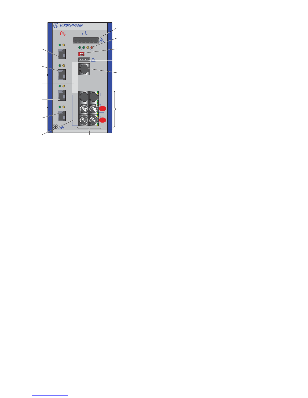
Figure 12: RS32 device variants with 4 uplink ports (example: RS32-
0802OOZZ...P...)
1 to 5 and 7 to 9 – see figure 9
6 – ports in compliance with 10/100BASE-T(X) (RJ45 connections; the
PoE-capable ports 7 to 10 are indicated accordingly)
Device variants RS22-... and RS32-... support Power over Ethernet (PoE) in
accordance with IEEE 802.3af.
They allow the connection and remote supply of, for example, IP telephones
(Voice over IP), webcams, sensors, printer servers and WLAN access points
via 10BASE-T/100BASE-TX. With PoE, these terminal devices are powered
by the twisted-pair cable.
The RS22-... and RS32-... devices provide four 10BASE-T/100BASE-TX
ports (RJ45 sockets) for connecting network segments or PoE terminal
devices (PD, Powered Device) for all IEEE802.3af classes up to a maximum
power output of 15.4 W.
The four PoE-capable ports are the four bottom ports on the right side of the
device (see figures in section “Number of ports and media for devices with
PoE” on page 35. The PoE ports are indicated in red on the device).
The voltage is supplied through the wire pairs transmitting the signal
(phantom voltage). The individual ports are not electrically insulated from
each other.
The following conditions are met in accordance with IEEE 802.3af:
Endpoint PSE
Alternative A
RS32
RM
Stand by
Aufkleber MAC-Adresse
IP-ADDRESS
V.24
USB
P
Stand by
FAULT
RM
ON
1
2
3
4
5
6
6
LS DA
1
LS DA
2
LS DA
3
LS DA
4
7
8
8
9
10
10
5
7
9
6
8
10
RS32-0802OOZZ...P...
FAULT
+48V(P1) 0V 0V +48V(P2)
Page 37
Installation RS20/22/30/32/40
Release 05 12/2015
37
1.2.2 PoE power units
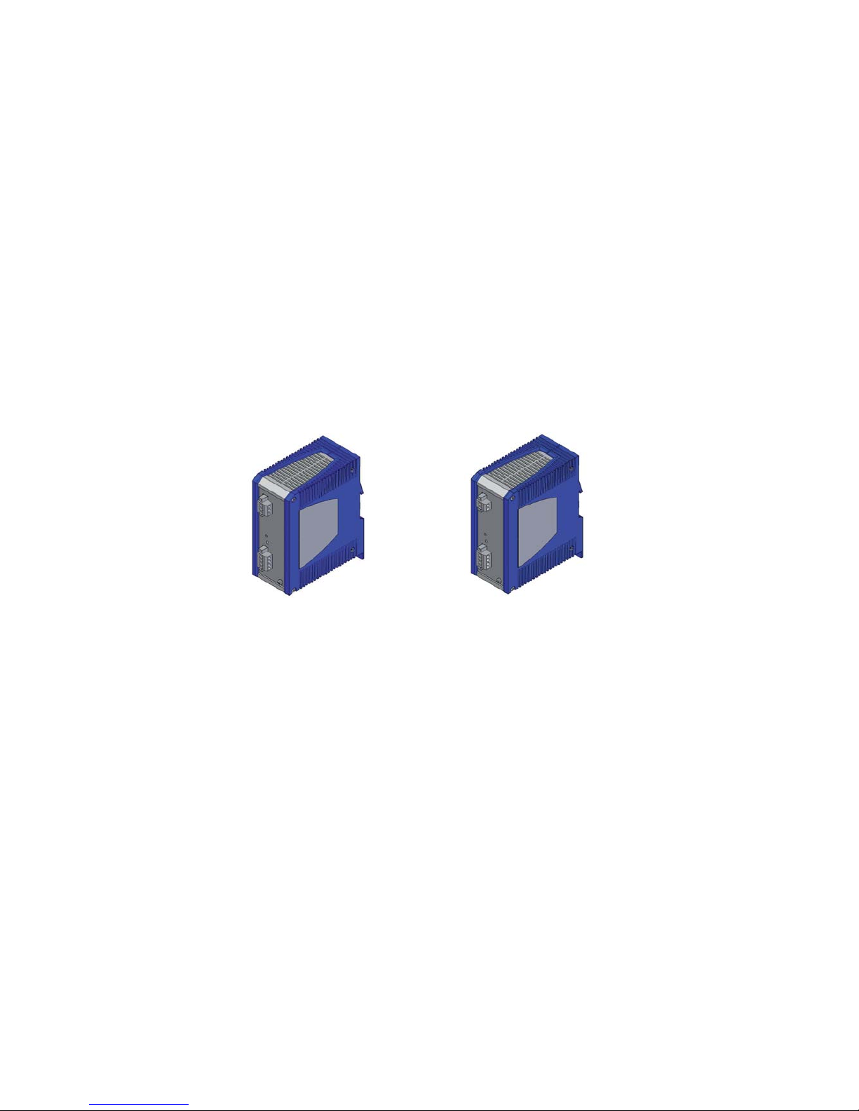
The following PoE power units are available for supplying the devices with
PoE voltage:
RPS90/48V LV: Low-voltage PoE power unit
Input voltage range: 24 V DC to 48 V DC
Power output at up to +60 °C: 90 W
Power output at +60 °C to +70 °C: 60 W
RPS90/48V HV: High-voltage PoE power unit
Input voltage range:
60 V DC to 250 V DC or 110 V AC to 230 V AC
You can choose between a DC or AC voltage connection.
Power output at up to +60 °C: 90 W
Power output at +60 °C to +70 °C: 60 W
The output voltage can be set in the range from 48 V DC to 54 V DC.
The default setting for the output voltage is 48 V DC.
RPS90/48V HV
RPS90/48V LV
Page 38
38
Installation RS20/22/30/32/40
Release 05 12/2015
1.3 Ethernet ports
You can connect end devices and other segments to the device ports using
twisted pair cables or optical fibers (F/O).
1.3.1 10/100/1000 Mbit/s twisted pair port
This port is an RJ45 socket.
The 10/100/1000 Mbit/s twisted pair port offers you the ability to connect
network components according to the IEEE 802.3 10BASE-T/100BASETX/1000BASE-T standard.
This port supports:
Autonegotiation
Autopolarity
Autocrossing (if autonegotiation is activated)
1000 Mbit/s full duplex
100 Mbit/s half-duplex mode, 100 Mbit/s full duplex mode
10 Mbit/s half-duplex mode, 10 Mbit/s full duplex mode
Delivery state: Autonegotiation activated
The socket housing is electrically connected with the front panel.
The pin assignment corresponds to MDI-X.
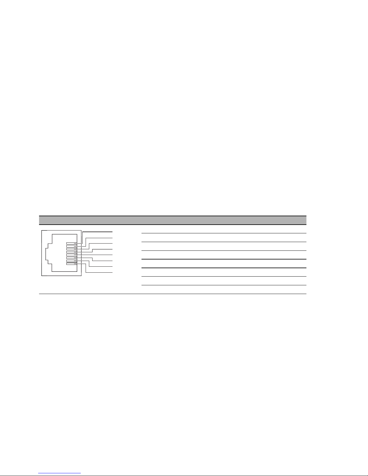
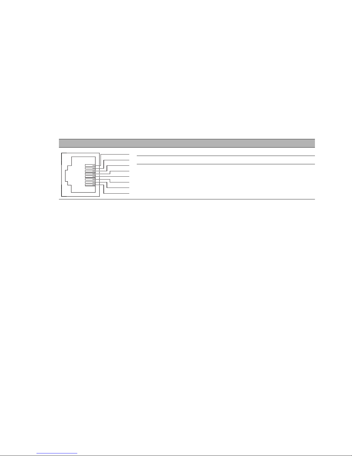
Pin Function
1BI_DB+
2BI_DB−
3BI_DA+
4 BI_DD+
5BI_DD−
6BI_DA−
7 BI_DC+
8BI_DC−
Table 7: Pin assignment of 10/100/1000 Mbit/s twisted pair port, RJ45 socket,
1000 Mbit/s mode, MDI-X mode
1
2
3
4
5
6
7
8
Page 39
Installation RS20/22/30/32/40
Release 05 12/2015
39
1.3.2 10/100 Mbit/s twisted pair port
This port is an RJ45 socket.
The 10/100 Mbit/s twisted pair port offers you the ability to connect network
components according to the IEEE 802.3 10BASE-T/100BASE-TX standard.
This port supports:
Autonegotiation
Autopolarity
Autocrossing (if autonegotiation is activated)
100 Mbit/s half-duplex mode, 100 Mbit/s full duplex mode
10 Mbit/s half-duplex mode, 10 Mbit/s full duplex mode
Delivery state: Autonegotiation activated
The socket housing is electrically connected with the front panel.
1.3.3 10/100 Mbit/s twisted-pair connection PoE
(RS22-.../RS32-...)
This port is an RJ45 socket.
The 10/100 Mbit/s PoE port allows you to connect network components as a
PoE voltage sink according to the standard IEEE 802.3 10BASET/100BASE-TX and IEEE 802.3af.
This port supports:
Autonegotiation
Autopolarity
Autocrossing (if autonegotiation is activated)
100 Mbit/s half-duplex mode, 100 Mbit/s full duplex mode
10 Mbit/s half-duplex mode, 10 Mbit/s full duplex mode
Power over Ethernet (PoE, at the last four ports of the device)
Delivery state: Autonegotiation activated
The socket housing is electrically connected with the front panel.
The PoE power is supplied via the wire pairs transmitting the signal (phantom
voltage).
Figure Pin Operation
1+2 One line pair: receiver path
3+6 One line pair: sender path
4,5,7,8 —
Table 8: Pin assignment of a TP/TX interface in MDI-X mode, RJ45 socket
1
2
3
4
5
6
7
8
Page 40

40
Installation RS20/22/30/32/40
Release 05 12/2015
1.3.4 1000 Mbit/s F/O port
This port is an SFP slot.
The 1000 Mbit/s F/O port offers you the ability to connect network
components according to the IEEE 802.3 100BASE-SX/1000BASE-LX
standard.
This port supports:
This port supports:
Autonegotiation
For device variants with the designation RS30-...02OOZZ... and RS32...02OOZZ... (4 uplink ports with SFP slot), you have the option of using
either Gigabit Ethernet SFP transceivers or Fast Ethernet SFP transceivers
at the two top ports, and Fast Ethernet SFP transceivers at the two bottom
ports.
See “Accessories” on page 75.
For the device variants RS40-..., you have the option of using either Gigabit
Ethernet SFP transceivers or Fast Ethernet SFP transceivers at the combo
ports.
See “Accessories” on page 75.
Verify that you connect LH ports only with LH ports, SX ports only with SX
ports, and LX ports only with LX ports.
1.3.5 100 Mbit/s F/O port
In device variants RS20 and RS22, these ports are DSC connectors or ST
connectors.
In device variants RS30, RS32 and RS40, these ports are SFP slots.
The 100 Mbit/s F/O port offers you the ability to connect network components
according to the IEEE 802.3 100BASE-FX standard.
This port supports:
Full or half duplex mode
Default setting: Full duplex
Note: Verify that the LH ports are connected only with LH ports, SM ports
only with SM ports, and MM ports only with MM ports.
Pin Function PoE voltage
1 RD+ Receive path Minus terminal
2RD− Receive path Minus terminal
3 TD+ Transmission path Plus terminal
6TD− Transmission path Plus terminal
4,5,7,8 —
Table 9: Pin assignment 10/100-Mbit/s PoE port, RJ45 socket, MDI-X mode,
phantom voltage
1
2
3
4
5
6
7
8
Page 41

Installation RS20/22/30/32/40
Release 05 12/2015
41
1.3.6 Gigabit combo port
You have the option of alternatively connecting a twisted pair cable via a
RJ45 socket or an optical fiber via a SFP transceiver to a combo port.
You obtain appropriate SFP transceivers as an accessory.
See “Accessories” on page 75.
By inserting a SFP transceiver, you deactivate automatically the
corresponding twisted pair interface.
10/100/1000 Mbit/s twisted pair port
See “10/100/1000 Mbit/s twisted pair port” on page 38.
100/1000 Mbit/s F/O port
This port is an SFP slot.
The 100/1000 Mbit/s F/O port offers you the ability to connect network
components according to the IEEE 802.3 100BASE-FX/1000BASESX/1000BASE-LX standard.
This port supports:
1000 Mbit/s full duplex
100 Mbit/s half-duplex mode, 100 Mbit/s full duplex mode
State on delivery:
100 Mbit/s full duplex when using a Fast Ethernet SFP transceiver
1000 Mbit/s full duplex when using a Gigabit Ethernet SFP transceiver
Media type Connection options
twisted pair cable Technical standard IEEE 802.3 10BASE-T/100BASE-
TX/1000BASE-T
Connection type RJ45
Fiber optic cable either Technical standard IEEE 802.3 100BASE-FX
Connection type Fast Ethernet SFP transceiver
or Technical standard IEEE 802.3 1000BASE-SX/LX
Connection type 1 Gigabit Ethernet SFP transceiver
Table 10: Combo ports: Connection options
Page 42
42
Installation RS20/22/30/32/40
Release 05 12/2015
1.4 Display elements
After the supply voltage is set up, the software starts and initializes itself.
Afterwards, the device performs a self-test. During this process, various
LEDs light up. The process takes around 60 seconds.
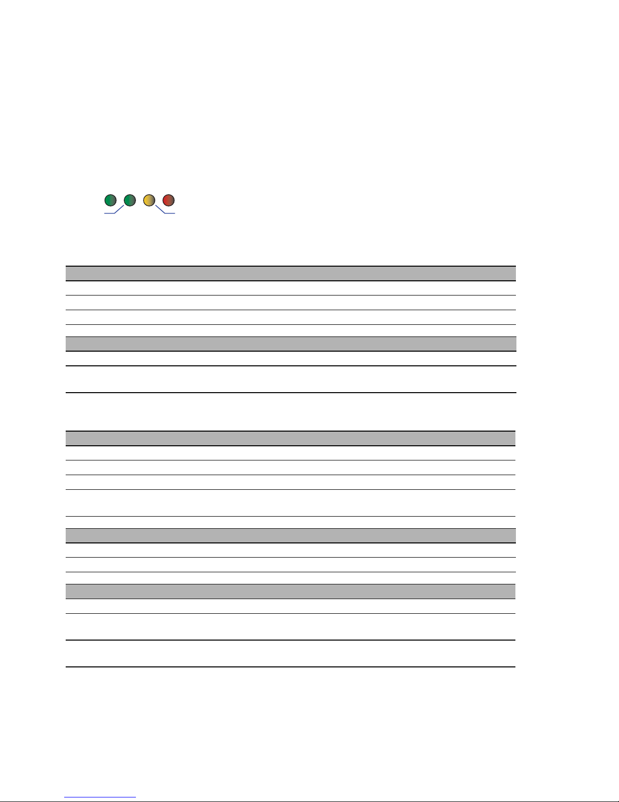
Device state
These LEDs provide information about conditions which affect the
operation of the whole device.
Figure 13: Device status LEDs
P - Power (green/yellow LED)
Glowing green Both supply voltages are on
Glowing yellow There is only one supply voltage (P1 or P2) on
Not glowing Supply voltages P1 and P2 are too low
FAULT - detected error, signal contact (red LED)
a
a. If the manual adjustment is active on the “FAULT” signal contact, then the detected error
display is independent of the setting of the signal contact.
Glowing red The signal contact is open, i.e. it is reporting a detected error.
Not glowing The signal contact is closed, i.e. it is not reporting
a detected error.
RM - Ring Manager (green/yellow LED)
Glowing green RM function active, redundant port disabled
Glowing yellow RM function active, redundant port enabled
Not glowing RM function not active
Flashing green Incorrect configuration of the HIPER-Ring (e. g. the ring is not
connected to the ring port).
Stand-by
Glowing green Stand-by mode enabled
Not glowing Stand-by mode not enabled
RM and Stand-by - display saving processes of the AutoConfiguration Adapter (ACA)
Flashing alternately Error during saving process.
LEDs flash synchronously, two
times a second
Loading configuration from the ACA.
LEDs flash synchronously,
once a second
Saving the configuration in the ACA.
P
Stand by
FAULT
RM
Page 43

Installation RS20/22/30/32/40
Release 05 12/2015
43
Port state
The green and yellow LEDs at the individual port display port-related
information. During the boot phase, these LEDs are used to display the
status of the boot procedure.
Figure 14: Port status LEDs
1 – Port status LEDs for isolated or single-row RJ45 sockets: one green
and one yellow LED per port.
2 – Port status LEDs for double-row RJ45 sockets: one LED per port,
glowing/flashing either green or yellow.
3 – Port status LEDs for DSC, ST, SFP
LS - link status (green LED)
Not glowing No valid connection.
Glowing green Valid connection.
Flashing green (1 time a period) Port is switched to stand-by.
Flashing green (3 times a
period)
Port is switched off.
DA - data (yellow LED)
Not glowing No data reception at corresponding port
Flashing yellow Data reception at corresponding port
DA
1
LS
LS DA
1132
LS
1
DA
Page 44
44
Installation RS20/22/30/32/40
Release 05 12/2015
1.5 Management interfaces
1.5.1 USB interface
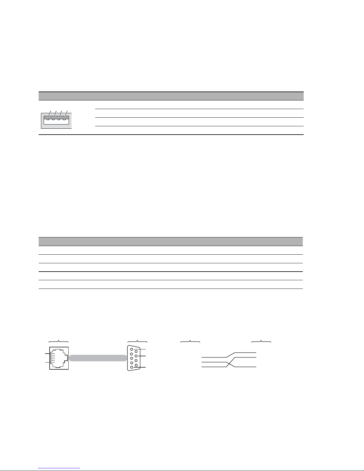
The USB socket is an interface for the local connection of an
AutoConfiguration Adapter ACA21-USB. It is used for saving/loading the
configuration data and diagnostic information, and for loading the software.
1.5.2 V.24 interface (external management)
The V.24 interface is an RJ11 socket.
At the V.24 connection, a serial interface is provided for the local connection
of an external management station (VT100 terminal or PC with
corresponding terminal emulation) or an AutoConfiguration Adapter ACA 11.
This enables you to set up a connection to the Command Line Interface (CLI)
and to the system monitor.
The socket housing is electrically connected to the front panel of the device.
The V.24 interface is not electrically isolated from the supply voltage.
Figure 15: Pin assignment of the V.24 interface and the DE9 connector
Note: The terminal cable is available as an accessory.
You will find a description of the V.24 interface in the “User Manual Basic
Configuration” document on the CD/DVD supplied.
Figure Pin Operation
1VCC (VBus)
2 − Data
3 + Data
4 Ground (GND)
Table 11: Pin assignment of the USB interface
VT 100 terminal settings
Speed 9600 Baud
Data 8 bit
Stopbit 1 bit
Handshake off
Parity none
1
2
4
3
1
1
8
5
6
2
3
5
1
2
3
4
5
6
CTS
n.c.
TX
GND
RX
RTS
RJ11
DB9
RJ11
DB9
Page 45

Installation RS20/22/30/32/40
Release 05 12/2015
45
2Installation
The devices have been developed for practical application in a harsh
industrial environment.
On delivery, the device is ready for operation.
Perform the following steps to install and configure the device:
Checking the package contents
Installing and grounding the device
Installing an SFP transceiver (optional)
Adjust DIP switch settings
Connecting the terminal block
Connecting the ferrite
Mounting the terminal block
Operating the device
Connecting data cables
Filling out the inscription label
Page 46
46
Installation RS20/22/30/32/40
Release 05 12/2015
2.1 Checking the package contents
Proceed as follows:
Check whether the package includes all items named in the section
“Scope of delivery” on page 74.
Check the individual parts for transport damage.
2.2 Installing and grounding the device
Only when using the PoE power supply unit RPS90/48V HV:
2.2.1 Installing the device onto the DIN rail
Verify that the device maintains the minimum clearing in order to meet the
climatic conditions:
Top and bottom device side: 3.94 in (10 cm)
Left and right device side: 0.79 in (2 cm)
WARNING
FIRE HAZARD
Install the device in a fire enclosure according to EN 60950-1.
Failure to follow these instructions can result in death, serious injury,
or equipment damage.
WARNING
ELECTRIC SHOCK
Install this device solely in a switch cabinet or in an operating site with
restricted access, to which maintenance staff have exclusive access.
Install the device at ambient temperatures greater than 113 °F (45 °C) in
“restricted access locations” based on EN 60950-1 exclusively.
Failure to follow these instructions can result in death, serious injury,
or equipment damage.
Page 47
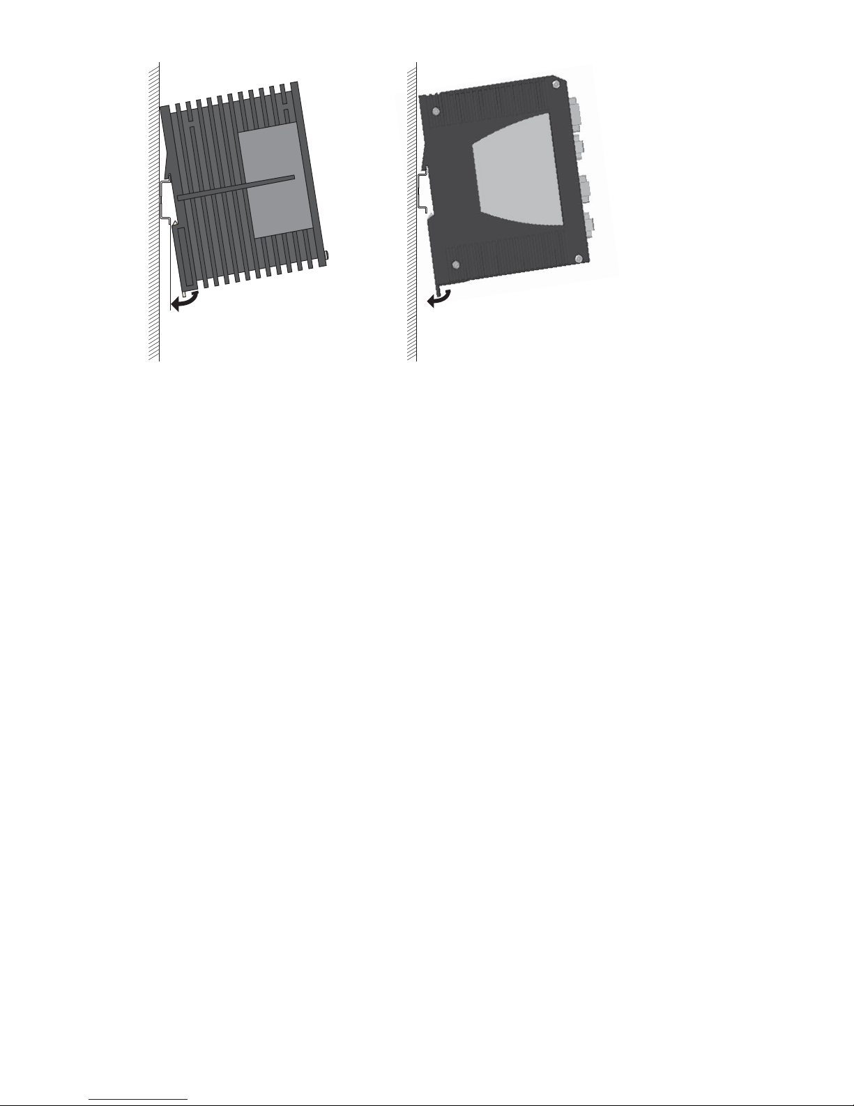
Installation RS20/22/30/32/40
Release 05 12/2015
47
To mount the device onto a horizontally mounted 35 mm DIN rail according
to DIN EN 60715, proceed as follows:
Slide the upper snap-in guide of the device into the DIN rail.
Pull down the locking gate using a screwdriver and press the lower part
of the device against the DIN rail.
Snap in the device by releasing the locking gate.
Note: The overall shield of a connected shielded twisted pair cable is
connected to the ground connector on the front panel as a conductor.
RS20/RS30/RS40
RS22/RS32
Page 48
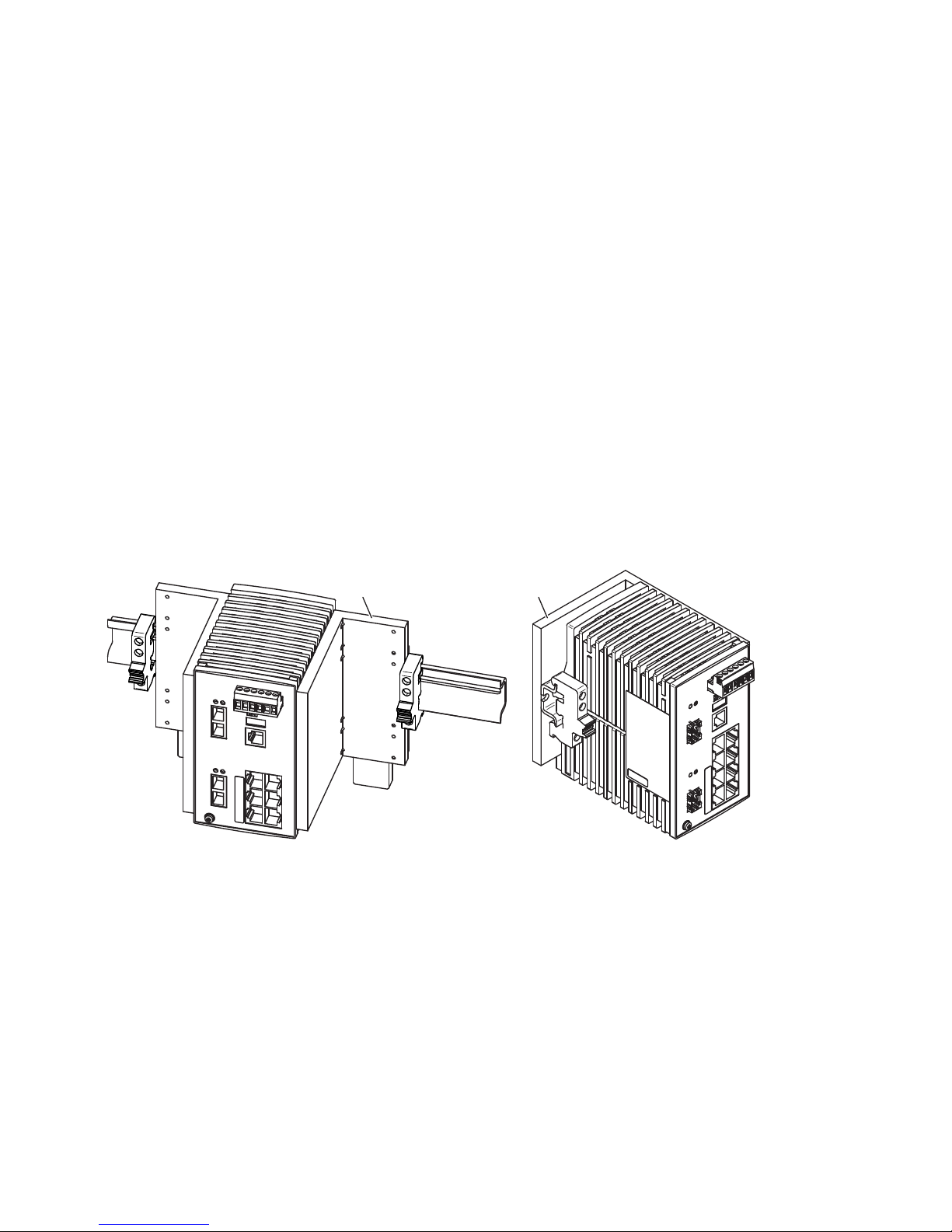
48
Installation RS20/22/30/32/40
Release 05 12/2015
2.2.2 DIN rail mounting on ships (RS30-0802...)
When you are mounting your RS30-0802... Open Rail device on a DIN rail on
ships and in similar applications, the Open Rail Mounting Kit available as an
accessory can be used to avoid excessive resonance.
You must use the Open Rail Mounting Kit with the order number
942 007-001 “Accessories” on page 75 when mounting your RS30-
0802... device on ships.
If you have very little space on your DIN rail, you can alternatively use
Open Rail Mounting Kit 942 007-101 (for mounting DIN rail on DIN rail).
Mount one mounting kit on each side of your RS30-0802... device, but at
least one mounting kit on one side of the RS30-0802... device. If possible,
position one side of the RS30-0802... device on a wall, or in a similarly
stable way. If you are positioning multiple RS30-0802... devices side by
side, mount the row of devices in the way described for a single device.
Mount a standard DIN rail stopper on both sides beside the mounting kit.
For more information on mounting the RS30-0802... on a DIN rail on ships,
see the “Open Rail Mounting Kit Mounting Instructions” manual supplied with
the Open Rail Mounting Kit.
Figure 16: Mounting the RS30-0802... on ships with the Open Rail Mounting Kit
1 - Open Rail Mounting Kit 942 007-001
2 - Open Rail Mounting Kit 942 007-101
21
Page 49
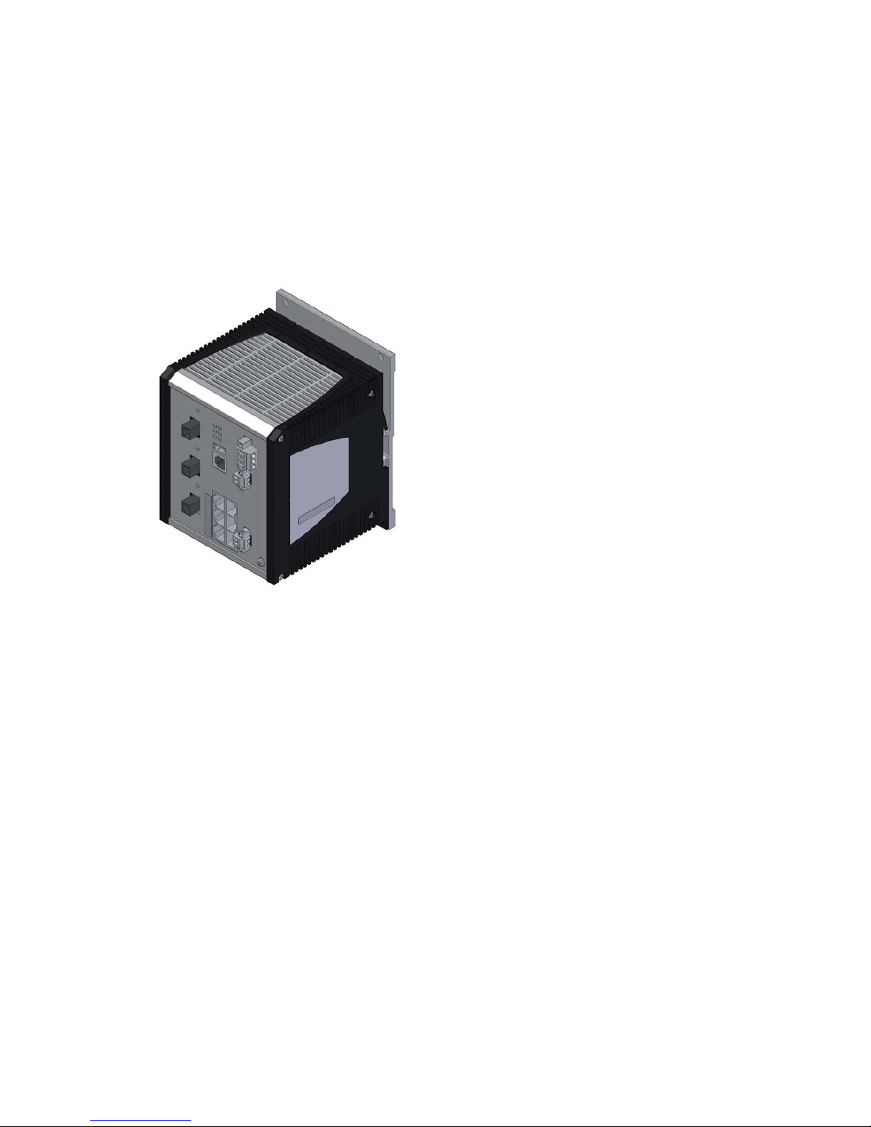
Installation RS20/22/30/32/40
Release 05 12/2015
49
2.2.3 Mounting on a vertical flat surface
Applies to the device variants RS22 and RS32:
You have the option of attaching the device to a vertical flat surface. This
requires a wall mounting plate, which you purchase as a separate accessory.
See “Accessories” on page 75.
Verify that the device maintains the minimum clearing in order to meet the
climatic conditions:
Top and bottom device side: 3.94 in (10 cm)
Left and right device side: 0.79 in (2 cm)
Mount the device on the wall plate as shown in the illustration. Insert the
upper snap-in guide of the device into the rail and press it down against
the rail until it snaps into place.
Fasten the wall plate (see on page 75 “Accessories”) on a level wall
surface using four screws.
2.2.4 Grounding the device
Use a wire diameter for the ground conductor that is no smaller than the
diameter of the supply voltage connection, however of at least 1.0 mm²
(AWG16).
With the RS20/RS30/RS40, the front panel of the device is grounded via the
separate ground screw.
With the RS22/RS32, the front panel and the metal housing of the device is
grounded via the separate ground screw.
Page 50
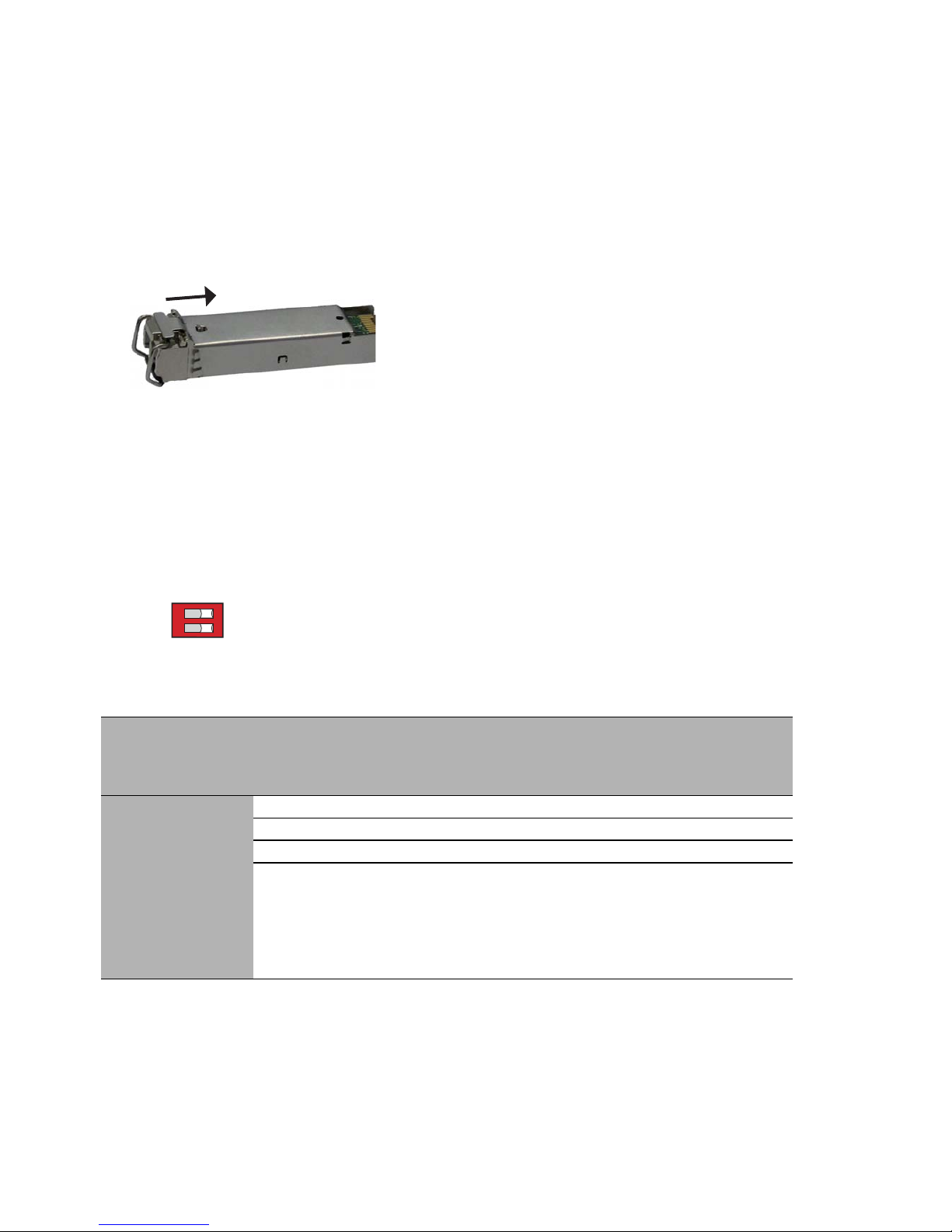
50
Installation RS20/22/30/32/40
Release 05 12/2015
2.3 Installing an SFP transceiver (optional)
Use only Hirschmann SFP transceivers which are suitable for usage with the
device.
See “Accessories” on page 75.
Proceed as follows:
Remove the protection cap from the SFP transceiver.
Push the transceiver with the lock closed into the slot until it latches in.
2.4 Adjust DIP switch settings
The 2-pin DIP switch on the front panel of the device gives you the following
options:
Figure 17: 2-pin DIP switch
Delivery state: both DIP switches “ON”.
Before starting operation of the device, check whether the default settings
of the DIP switch correspond to your requirements.
Switch
RM
Position
Switch
Stand-by
Position
Ring
redun
dancy
Coupli
ng
switch
Ring
manager
Coupli
ng
manag
er
Ring
port
Contro
l port
Coupl
ing
port
Software
configuratio
n
OFF OFF an an aus aus 1 + 2
ON OFF on on on off 1 + 2
OFF ON on on off on 1 + 2 3 4
ON ON SW
configuration
has priority
over DIP
switch
configuration
RM
Stan d b y
ON
Page 51
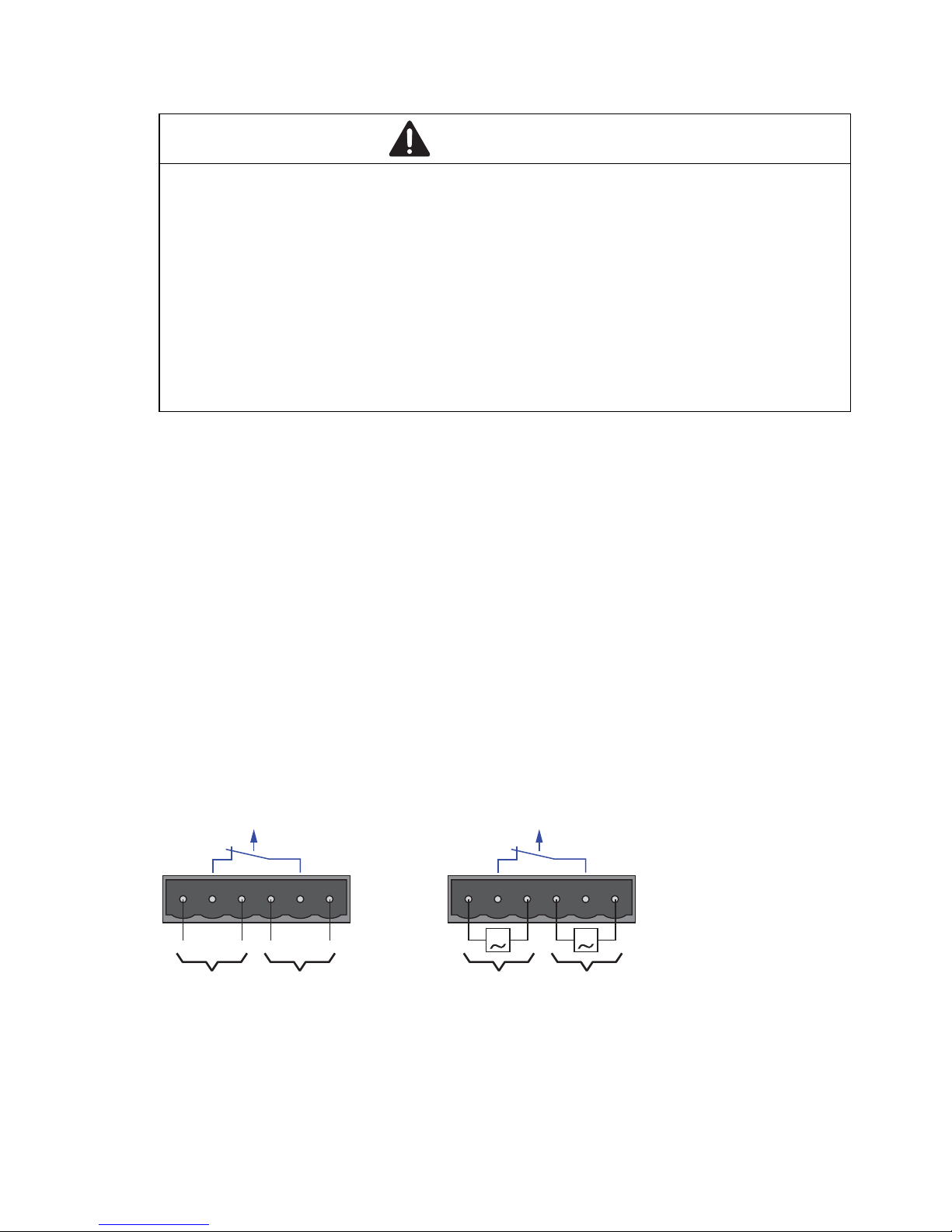
Installation RS20/22/30/32/40
Release 05 12/2015
51
2.5 Connecting the terminal block
2.5.1 RS20/RS30/RS40: supply voltage and
signal contact
The supply voltage and the signal contact are connected via a 6-pin terminal
block with a snap lock.
Supply voltage for RS20/RS30/RS40
The supply voltage can be connected redundantly. Both inputs are
uncoupled. There is no distributed load. With redundant supply, the power
supply unit with the higher output voltage supplies the device on its own.
The supply voltage is electrically isolated from the housing.
See “Insulation voltage” in section “Technical data” on page 64.
You can choose between DC or AC voltage when connecting the supply
voltage. You use the +24V and 0V pins to connect the AC voltage (see
figure 18).
Figure 18: Connecting the supply voltage at the 6-pin terminal block
1 – DC voltage, voltage range: 9.6 V DC to 60 V DC
2 – AC voltage, voltage range: 18 V AC to 30 V AC
WARNING
ELECTRIC SHOCK
Connect only a supply voltage that corresponds to the type plate of your
device.
Never insert sharp objects (small screwdrivers, wires, etc.) into the
connection terminals for electric conductors, and do not touch the terminals.
Observe the maximum values for the contact load of the signal contact.
Failure to follow these instructions can result in death, serious injury,
or equipment damage.
FAULT
G G
+24V(P1) 0V 0V +24V(P2)
FAULT
+24V(P1) 0V 0V +24V(P2)
+-
-+
1 1 2 2
Page 52

52
Installation RS20/22/30/32/40
Release 05 12/2015
With a non-redundant supply of the supply voltage, the device reports the
loss of a supply voltage. You can prevent this message by changing the
configuration in the Management.
Signal contact for RS20/RS30/RS40
The signal contact (“FAULT”, for pin assignment of terminal block, see
figure 18) monitors the functioning of the device, thus enabling remote
diagnostics. You can specify the type of function monitoring in the
Management.
You can also use the graphical user interface of the switch to switch
the signal contact manually and thus control external devices.
The potential-free signal contact (relay contact, closed circuit) reports
through a break in contact:
The detected inoperability of at least one of the two voltage supplies
(voltage supply 1 or 2 is below the threshold value).
The device is not operational.
The failure of the connection on at least one port.
The report of the link status can be masked by the Management for
each port. In the delivery state, is deactivated.
Failure of the ring redundancy reserve.
Errors detected during the self-diagnostic test.
Incorrect configuration of the HIPER-Ring or ring coupling.
The following condition is also reported in RM mode:
Ring redundancy reserve is available. On delivery, there is no ring
redundancy monitoring.
Pull the terminal block off the device and connect the power supply
and signal lines.
Page 53

Installation RS20/22/30/32/40
Release 05 12/2015
53
2.5.2 RS22/RS32: supply voltage and signal contact
The PoE voltage and the signal contact are connected via a 6-pin terminal
block with a snap lock.
The RS22/RS32 devices are supplied with PoE voltage (48 V DC safety low
voltage) via an external power supply unit.
The RS22/RS32 devices fulfill the technical data and the
certifications when using the RPS90/48V LV and RPS90/48V HV power units
from Hirschmann. Only use these power units, to ensure that the
specifications are fulfilled.
Make sure that the external power supply unit you use to provide the PoE
voltage fulfills the following basic prerequisites:
Insulation requirements according to IEEE 802.3af (insulation
resistance 48 V, output to “rest of the world” 2,250 V DC for 1 min.).
Output power < 100 W
Current limitation < 5 A
The power supply unit and the devices with PoE ports form a “limited
power source” according to IEC 60950-1.
The external PoE power supply unit must be able to provide the power
for the connected PDs (Power Devices) and for the Switch.
RPS90/48V LV: connecting the input voltage
With the RPS90/48V LV low-voltage PoE power unit, you connect a DC
supply voltage of 24 V DC to 48 V DC at the input connection.
The supply voltage is connected via pin 1 and pin 2.
First connect the protective conductor to the protective conductor
terminal.
Connect the DC voltage to the 2-pin terminal block.
Use a supply cable with a maximum length of 2 meters to the power
unit.
Figure Pin Assignment Supply voltage range
1 Minus terminal of the supply voltage Low voltage input voltage: 24
V DC to 48 V DC
2 Plus terminal of the supply voltage
Table 12: Connecting the low-voltage supply voltage at PoE power unit RPS90/48V
LV
2
1
Page 54
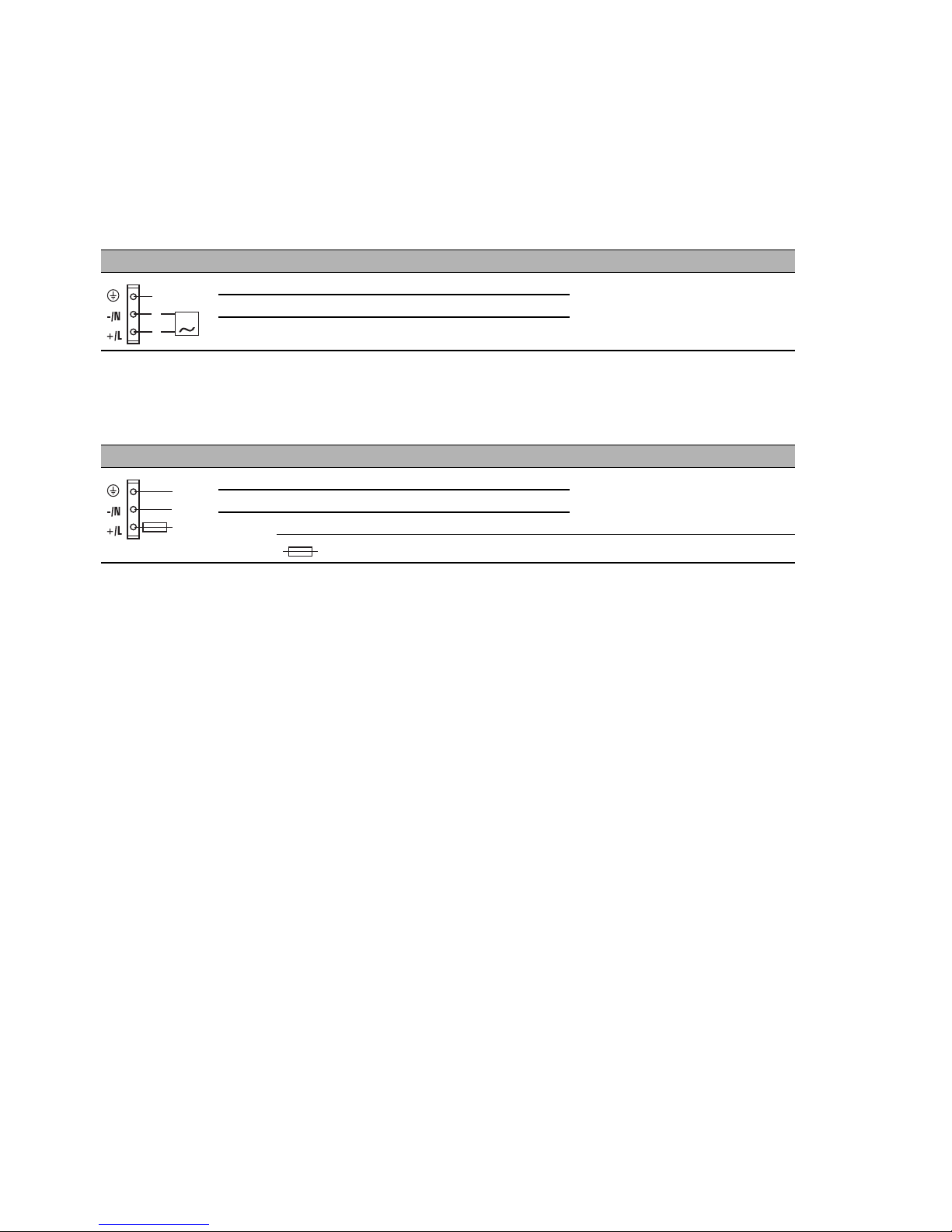
54
Installation RS20/22/30/32/40
Release 05 12/2015
RPS90/48V HV: connecting the input voltage
With the RPS90/48V HV high-voltage PoE power unit, you connect either
a DC or AC supply voltage at the input connection:
60 V DC to 250 V DC
110 V AC to 230 V AC
The supply voltage is connected via pin 2 and pin 3, and the protective
conductor is connected via pin 1.
First connect the protective conductor to the protective conductor
terminal.
Connect the supply voltage via the 3-pin terminal block. Pay attention
to the +/L and -/N connections.
If the neutral conductor or the minus terminal of the supply voltage is
not grounded, install a suitable fuse in the input line.
For supply voltages > 125 V DC:
Install a suitable external fuse in the supply voltage input line of the
plus terminal.
Use a supply cable with a maximum length of 2 meters to the power
unit.
Figure Pin Assignment Supply voltage range
1 Protective conductor High voltage input voltage:
110 V AC to 230 V AC
2 Minus terminal of the supply voltage
3 Plus terminal of the supply voltage
Table 13: Connecting the high-voltage supply voltage at PoE power unit
RPS90/48V HV (AC voltage)
Figure Pin Assignment Supply voltage range
1 Protective conductor High-voltage input voltage: 60
V DC to 250 V DC
2 Minus terminal of the supply voltage
3 Plus terminal of the supply voltage
= external fuse for supply voltages > 125 V DC
Table 14: Connecting the high-voltage supply voltage at PoE power unit
RPS90/48V HV (DC voltage)
G
1
2
3
1
2
3
Page 55
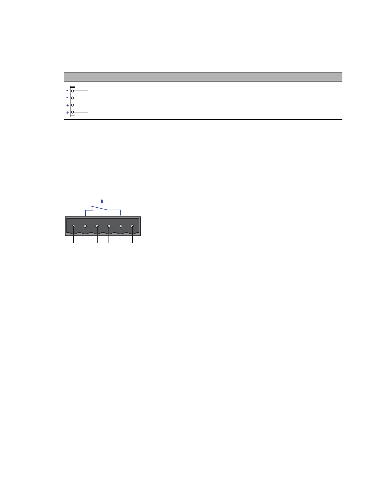
Installation RS20/22/30/32/40
Release 05 12/2015
55
RS22/RS32 supply voltage
The RPS90/48V LV and RPS90/48V HV PoE power supply units provide
an output voltage of typically 48 V DC for supplying the RS22-.../RS32-...
devices with the PoE voltage.
Connect the PoE voltage to the 6-pin terminal block for the device
included in the delivery.
Make sure the following requirements are met:
Supply line length < 0.5 m.
Figure 19: Connecting the PoE voltage at the 6-pin terminal block of the RS22/RS32
devices
Figure Pin Assignment Supply voltage range
1+2 Minus terminal of the output voltage Output voltage (PoE voltage)
range:
48 V DC to 54 V DC
(default: 48 V DC)
3+4 Plus terminal of the output voltage
Table 15: Output voltage of RPS90/48V LV and RPS90/48V HV PoE power units
1
2
3
4
FAULT
+48V(P1) 0V 0V +48V(P2)
+-
-+
Page 56

56
Installation RS20/22/30/32/40
Release 05 12/2015
RS22/RS32 signal contact
The signal contact (“FAULT”, for pin assignment of terminal block, see
figure 19) monitors the functioning of the device, thus enabling remote
diagnostics. You can specify the type of function monitoring in the
Management.
You can also use the graphical user interface of the switch to switch
the signal contact manually and thus control external devices.
The potential-free signal contact (relay contact, closed circuit) reports
through a break in contact:
The detected inoperability of at least one of the two voltage supplies
(voltage supply 1 or 2 is below the threshold value).
The device is not operational.
The failure of the connection on at least one port.
The report of the link status can be masked by the Management for
each port. In the delivery state, is deactivated.
Failure of the ring redundancy reserve.
Errors detected during the self-diagnostic test.
Incorrect configuration of the HIPER-Ring or ring coupling.
The following condition is also reported in RM mode:
Ring redundancy reserve is available. On delivery, there is no ring
redundancy monitoring.
Pull the terminal block off the device and connect the power supply
and signal lines.
2.6 Mounting the terminal block
Mount the terminal block for the voltage supply and signal contact on the
front of the device using the snap lock. Verify that the snap lock latches in
place.
Page 57
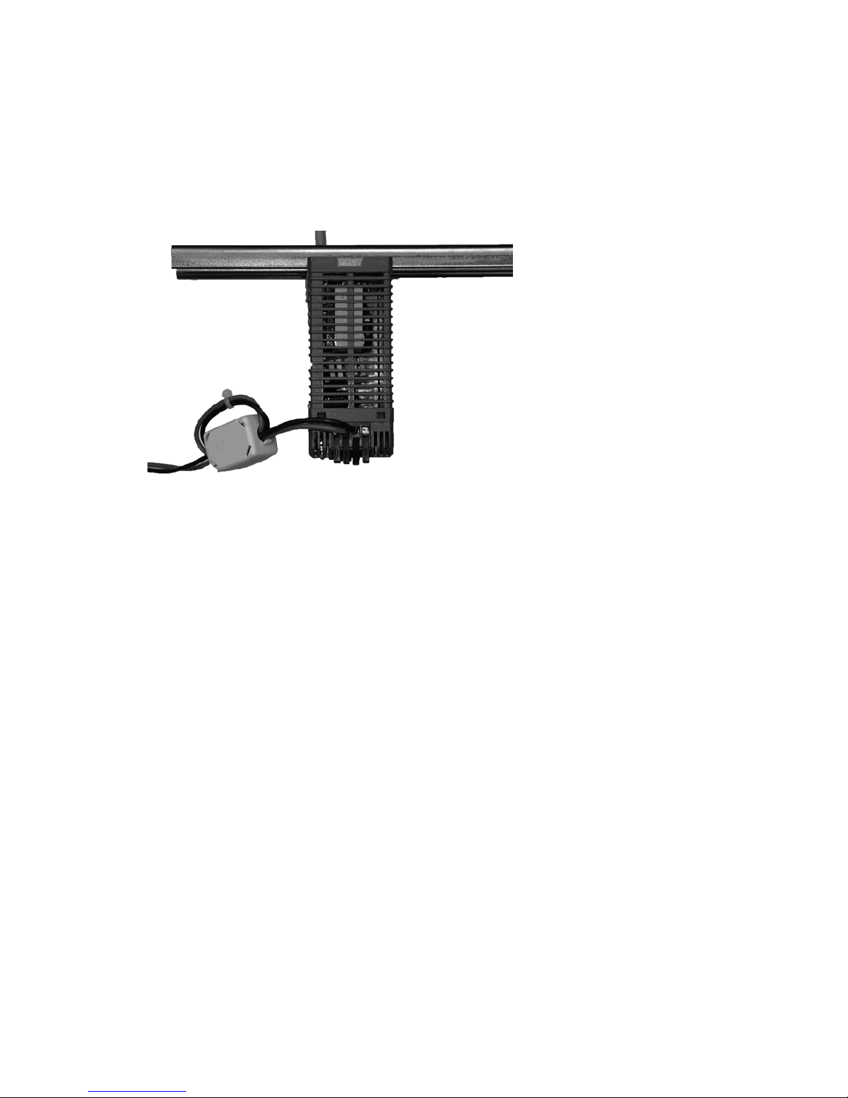
Installation RS20/22/30/32/40
Release 05 12/2015
57
2.7 Connecting the ferrite
Note: For PoE devices with 16 or more ports
(RS22-16..., RS22-17..., RS22-24... and RS22-25...):
To adhere to EMC conformity, you connect the ferrite supplied to the voltage
input via the power supply cable.
Insert both cables of the 48V output through the ferrite twice.
Lock the ferrite.
Position the ferrite as close as possible to the voltage input (max. distance
19.7 inches (50 cm)).
To open the ferrite use the key supplied.
2.8 Operating the device
By connecting the supply voltage via the terminal block, you start the
operation of the device.
Page 58
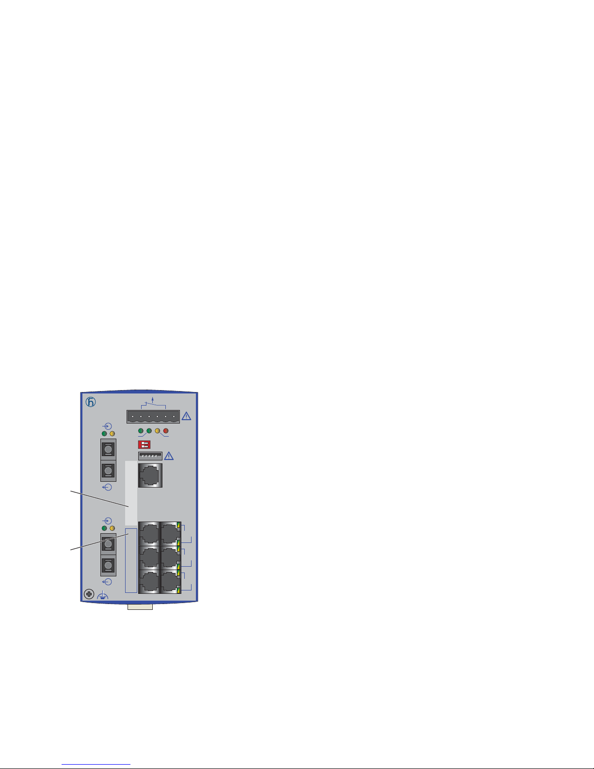
58
Installation RS20/22/30/32/40
Release 05 12/2015
2.9 Connecting data cables
Note the following general recommendations for data cable connections in
environments with high electrical interference levels:
Keep the length of the data cables as short as possible.
Use optical data cables for the data transmission between the buildings.
When using copper cables, provide a sufficient separation between the
power supply cables and the data cables. Ideally, install the cables in
separate cable channels.
Verify that power supply cables and data cables do not run parallel over
longer distances, and that ideally they are installed in separate cable
channels. If reducing the inductive coupling is necessary, verify that the
power supply cables and data cables cross at a 90° angle.
Use shielded cables (SF/UTP cables as per ISO/IEC 11801:2002).
Connect the data cables according to your requirements.
For further information see “Description of the device variants” on page 21.
2.10 Filling out the inscription label
The information field for the IP address helps you identify your device.
Figure 20: Label area for IP address of device
1 – IP address of device (label area)
2 – MAC address of device (label)
RS20
LS DA
RM
+24V(P1) 0V 0V
FAULT
+24V(P2)
Sta nd by
Aufkleber MAC-Adresse
IP-ADDRESS
2
LS DA
1
3
5
7
4
6
8
V.2 4
USB
P
Sta nd by
FAULT
RM
ON
2
1
Page 59
Installation RS20/22/30/32/40
Release 05 12/2015
59
3 Making basic settings
The IP parameters must be entered when the device is installed for the first
time. The device provides the following options for configuring IP addresses:
Configuration via V.24 connection
Configuration using the HiDiscovery protocol
Configuration via BOOTP
Configuration via DHCP
Configuration via DHCP (Option 82)
Configuration using AutoConfiguration Adapter
Further information on the basic settings of the device can be found in the
“Basic Configuration” user manual on the CD/DVD.
Default settings
IP address: The device looks for the IP address using DHCP
Password for management:
Login: user; password: public (read only)
Login: admin; password: private (read and write)
V.24 data rate: 9,600 Baud
Ring redundancy: disabled
Ethernet ports: link status is not evaluated (signal contact)
Optical 100 Mbit/s ports: 100 Mbit/s, full duplex
All other ports: autonegotiation
Ring Manager disabled (DIP switch RM and Stand-by: ON)
Stand-by coupling disabled (DIP switch RM and stand-by: ON), Port 4
= control port, Port 3 = coupling port for redundant ring coupling
Rapid Spanning Tree enabled
WARNING
UNINTENTIONAL OPERATION IN DEVICE
Install and maintain a process that assigns a unique IP address to every
device in the network.
Failure to follow these instructions can result in death, serious injury,
or equipment damage.
Page 60

60
Installation RS20/22/30/32/40
Release 05 12/2015
4 Monitoring the ambient air temperature
Operate the device below the specified maximum ambient air temperature
exclusively.
See “General technical data” on page 64.
The ambient air temperature is the temperature of the air at a distance of 2 in
(5 cm) from the device. It depends on the installation conditions of the device,
e.g. the distance from other devices or other objects, and the output of
neighboring devices.
The temperature displayed in the CLI and the GUI is the internal temperature
of the device. It is higher than the ambient air temperature. The maximum
internal temperature of the device named in the technical data is a guideline
that indicates to you that the maximum ambient air temperature has possibly
been exceeded.
Page 61

Installation RS20/22/30/32/40
Release 05 12/2015
61
5 Maintenance and service
When designing this device, Hirschmann largely avoided using high-wear
parts. The parts subject to wear and tear are dimensioned to last longer
than the lifetime of the product when it is operated normally. Operate this
device according to the specifications.
Relays are subject to natural wear. This wear depends on the frequency
of the switching operations. Check the resistance of the closed relay
contacts and the switching function depending on the frequency of the
switching operations.
Hirschmann is continually working on improving and developing their
software. Check regularly whether there is an updated version of the
software that provides you with additional benefits. You find information
and software downloads on the Hirschmann product pages on the
Internet (www.hirschmann.com).
Depending on the degree of pollution in the operating environment, check
at regular intervals that the ventilation slots in the device are not
obstructed.
Note: You will find information about the complaints and returns procedures
on the Internet under
http://www.beldensolutions.com/en/Service/Repairs/index.phtml .
Page 62
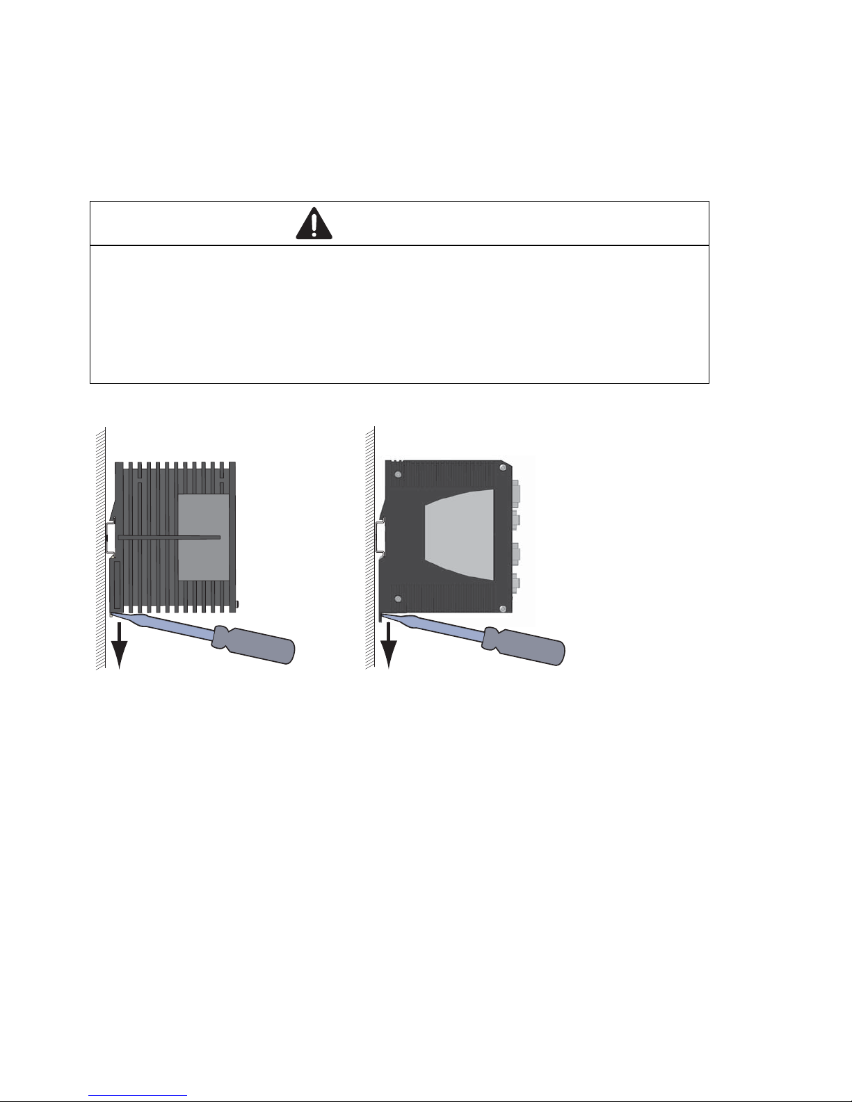
62
Installation RS20/22/30/32/40
Release 05 12/2015
6 Disassembly
6.1 Removing the device
Proceed as follows:
Disconnect the data cables.
Disable the supply voltage.
Disconnect the terminal blocks.
Disconnect the grounding.
Insert a screwdriver horizontally below the housing into the locking gate.
Without tilting the screwdriver, pull the locking gate down and tilt the
device upwards.
WARNING
ELECTRIC SHOCK
Disconnect the grounding only after disconnecting all other cables.
Failure to follow these instructions can result in death, serious injury,
or equipment damage.
RS20/RS30/RS40 RS22/RS32
Page 63
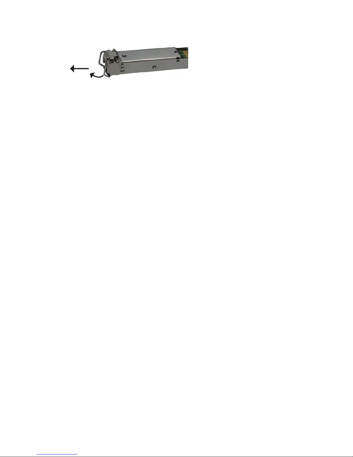
Installation RS20/22/30/32/40
Release 05 12/2015
63
6.2 Removing an SFP transceiver (optional)
Proceed as follows:
Pull the SFP transceiver out of the slot by means of the opened lock.
Close the SFP transceiver with the protective cap.
1
2
Page 64

64
Installation RS20/22/30/32/40
Release 05 12/2015
7 Technical data
General technical data
Dimensions
B × H × T
RS20-0400...
RS20-08..., RS20-09..., RS30-0802
RS20-16..., RS20-17..., RS30-1602
RS20-24..., RS20-25..., RS30-2402
RS40-0009CCCCS...
RS40-0009CCCCE...,
RS40-0009CCCCT...
1.85 in. × 5.16 in. × 4.37 in.
(47 mm × 131 mm × 111 mm)
2.91 in. × 5.16 in. × 4.37 in.
(74 mm × 131 mm × 111 mm)
4.33 in. × 5.16 in. × 4.37 in.
(110 mm × 131 mm × 111 mm)
4.33 in. × 5.16 in. × 4.37 in.
(110 mm × 131 mm × 111 mm)
2.91 in. × 5.16 in. × 4.37 in.
(74 mm × 131 mm × 111 mm)
4.33 in. × 5.16 in. × 4.37 in.
(110 mm × 131 mm × 111 mm)
RS22-08..., RS22-09..., RS32-0802
RS22-16..., RS22-17..., RS32-1602
RS22-24..., RS22-25..., RS32-2402
3.54 in. × 5.39 in. × 4.53 in.
(90 mm × 137 mm × 115 mm)
4.72 in. × 5.39 in. × 4.53 in.
(120 mm × 137 mm × 115 mm)
4.72 in. × 5.39 in. × 4.53 in.
(120 mm × 137 mm × 115 mm)
PoE power supply unit RPS
90/48V LV
PoE power supply unit RPS
90/48V HV
2.36 in. × 5.39 in. × 4.53 in.
(60 mm × 137 mm × 115 mm)
2.36 in. × 5.39 in. × 4.53 in.
(60 mm × 137 mm × 115 mm)
Weight RS20-0400...
RS20-08..., RS20-09..., RS30-0802
RS20-16..., RS20-17..., RS30-1602
RS20-24..., RS20-25..., RS30-2402
RS40-0009CCCCS...
RS40-0009CCCCE...,
RS40-0009CCCCT...
14.11 oz (400 g)
14.46 oz (410 g)
21.16 oz (600 g)
20.90 oz (650 g)
18.70 oz (530 g)
21.16 oz (600 g)
RS22-08..., RS22-09..., RS32-0802
RS22-16..., RS22-17..., RS32-1602
RS22-24..., RS22-25..., RS32-2402
28.92 oz (820 g)
40.57 oz (1150 g)
42.33 oz (1200 g)
PoE power supply unit RPS
90/48V LV
PoE power supply unit RPS
90/48V HV
27.16 oz (770 g)
26.10 oz (740 g)
Power supply
RS20-..., RS30-...,
RS40-...
Nominal voltage AC 24 V
Max. voltage range AC 18 V ... 30 V
(incl. max. tolerances)
Rated voltage range DC 12 V ... 48 V
Max. voltage range DC 9.6 V ... 60 V (incl. max. tolerances)
Connection type 6-pin terminal block with snap lock
Power loss buffer > 10 ms
Back-up fuse Nominal rating:
Characteristic:
3.5 A
slow blow
Peak inrush current < 14 A
Page 65

Installation RS20/22/30/32/40
Release 05 12/2015
65
Power supply
RS22-..., RS32-...
Nominal voltage AC 48 V
Max. voltage range AC 47 V ... 52 V
(incl. max. tolerances)
Connection type 6-pin terminal block with snap lock
Power loss buffer > 10 ms
Back-up fuse Nominal rating:
Characteristic:
3.5 A
slow blow
Peak inrush current < 14 A
PoE power unit
RPS90/48V HV
Nominal voltage AC 110 V ... 230 V, 50 Hz ... 60 Hz
Voltage range AC 90 V ... 265 V, 47 Hz ... 63 Hz
(incl. max. tolerances)
Power consumption at 110 V AC
Power consumption at 230 V AC
1.00 A
0.50 A
Nominal voltage DC 60 - 250 V
Voltage range DC 48 V ... 320 V (incl. max. tolerances)
Current consumption at 60 V DC
Current consumption at 250 V DC
1.70 A
0.39 A
Connection type 3-pin terminal block
Output voltage 48 V ... 54 V DC (variable, default
value: 48 V DC)
Power output At up to +60 °C: 90 W
At +60 °C to +70 °C: 60 W
Power loss buffer > 10 ms
Back-up fuse Nominal rating:
Characteristic:
6.3 A
slow blow
Peak inrush current < 15 A
PoE power unit
RPS90/48V LV
Nominal voltage DC 24 V ... 48 V
Voltage range DC 18 V ... 60 V (incl. max. tolerances)
Current consumption at 24 V DC
Current consumption at 48 V DC
4.20 A
2.10 A
Connection type 2-pin terminal block
Output voltage 48 V ... 54 V DC (variable, default
value: 48 V DC)
Power output At up to +60 °C: 90 W
At +60 °C to +70 °C: 60 W
Power loss buffer > 10 ms
Back-up fuse Nominal rating:
Characteristic:
10 A
slow blow
Peak inrush current < 15 A
Overload current
protection at input
Non-replaceable fuse
Insulation voltage
between supply
voltage connections
and housing
800 V DC
Protective elements limit the
insulation voltage to 90 V DC (1 mA)
“FAULT”
signal contact
Switching current max. 1 A, SELV
Switching voltage max. 60 V DC or max. 30 V AC,
SELV
Page 66

66
Installation RS20/22/30/32/40
Release 05 12/2015
Environment Storage temperature
(ambient air)
Standard: −40 °F ... +158 °F
(−40 °C ... +70 °C )
Extended −40 °F ... +185 °F
(−40 °C ... +85 °C)
Humidity 10 % ... 95 %
(non-condensing)
Air pressure Up to 2000 m (795 hPa), higher
altitudes on request
Minimum clearance around the
device
Top and bottom device side: 3.94 in
(10 cm)
Left and right device side: 0.79 in
(2 cm)
Operating
temperature
a
RS20/RS30/RS40 Standard: +32 °F ... +140 °F
(0 °C ... +60 °C)
Extended −40 °F ... +158 °F
(−40 °C ... +70 °C )
RS22-..., RS32-... Standard: 0 °C ... +60 °C
b)
Extended: −40 °F ... +140 °F
(−40 °C to +60 °C)
c)
RS40-...B... (ATEX/IECEx)
Standard (S)
Temperature code T4:
+32 °F ... +140 °F (0 °C ... +60 °C)
RS40-...B... (ATEX/IECEx)
Extended (E and T)
Temperature code T3:
−40 °F ... +158 °F
(−40 °C ... +70 °C)
Temperature code T4:
−40 °F ... +140 °F
(−40 °C ... +60 °C)
RPS90/48V HV −40 °F ... +158 °F
(−40 °C ... +70 °C)
Cold start at temperatures > −30 °C
RPS90/48V LV −40 °F ... +158 °F (−40 °C ...
+70 °C)
Cold start at temperatures > −30 °C
at an input voltage ≥ 21.6 V DC
Pollution degree 2
Protection classes Laser protection Class 1 in compliance with IEC
60825-1
Degree of protection IP20
a. Exclusively use SFP modules with the “EEC” extension at temperatures > 60 °C and < 0 °C.
b. With a UL-508, ATEX/IECEx, or ISA 12.12.01 approval, the maximum operating
temperature for the standard ‘S’ temperature range for PoE-capable devices (RS22-...,
RS32-...) is +122 °F (+50 °C).
c. With a UL-508, ATEX/IECEx, or ISA 12.12.01 approval, the maximum operating
temperature for the extended ‘E’ and ‘T’ temperature range for PoE-capable devices (RS22..., RS32-...) is +122 °F (+50 °C).
Page 67
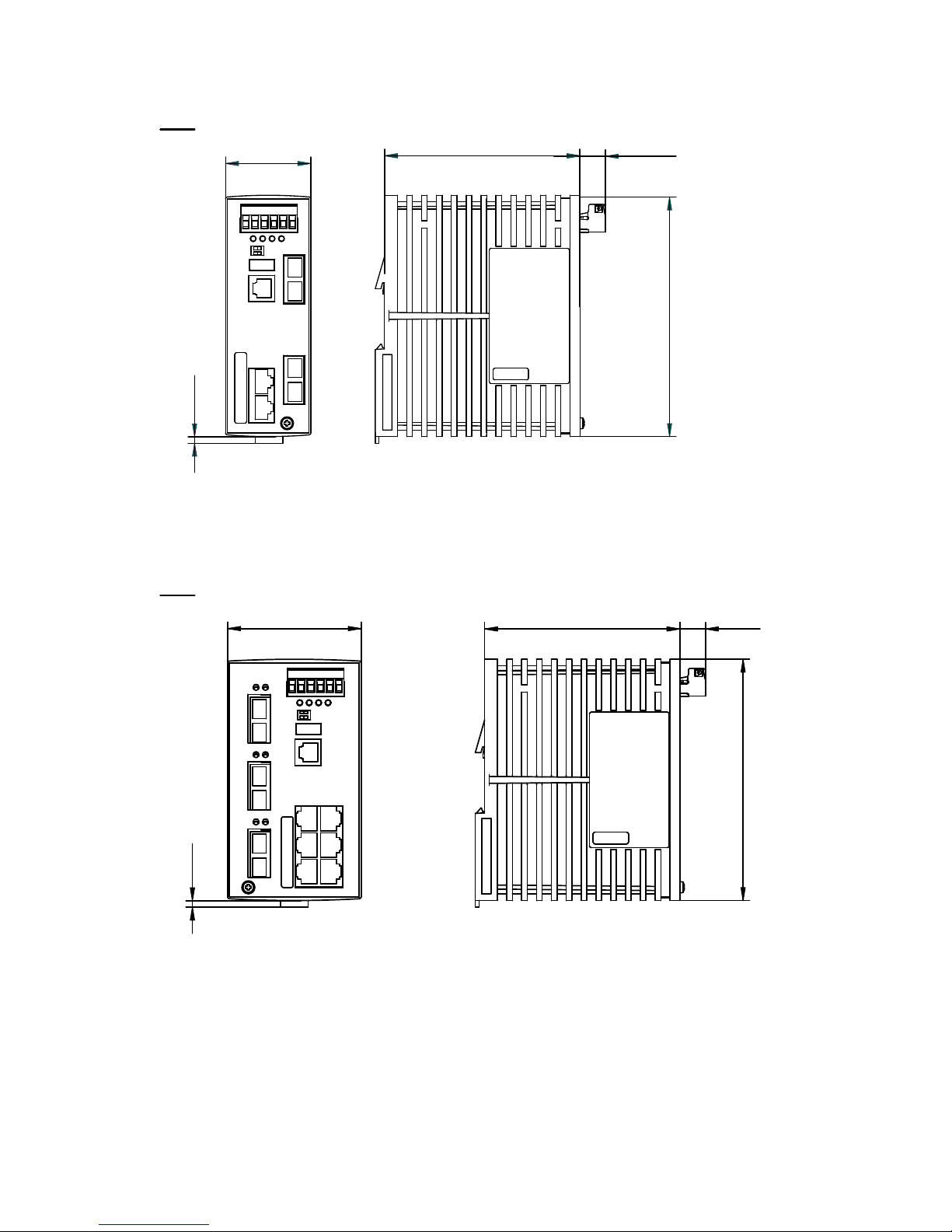
Installation RS20/22/30/32/40
Release 05 12/2015
67
Dimension drawings
Figure 21: Dimensions of device variants RS20-04...
with operating temperature characteristic value S, T and E
Figure 22: Dimensions of device variants
- RS20-08... and RS20-09... with operating temperature
characteristic value S, T and E
- RS30-08... with operating temperature characteristic value S, T and E
- RS40-09... with operating temperature characteristic value S
46
130
3,5
14
mm
inch
5.12
0.14
4.17
0.55
1.81
106
130
5.12
106
14
3,5
72
mm
inch
0.14
0.55
4.172.84
Page 68
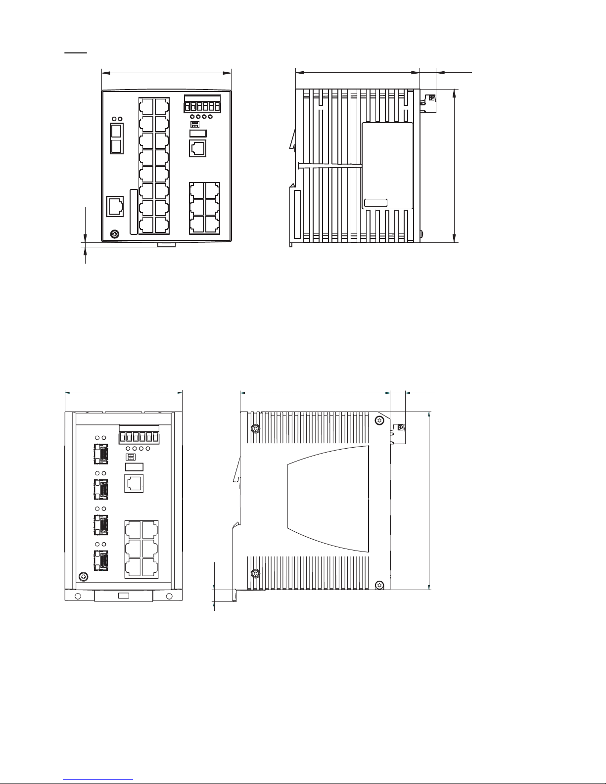
68
Installation RS20/22/30/32/40
Release 05 12/2015
Figure 23: Dimensions of device variants
- RS20-16... , RS20-17... and RS20-24... with operating temperature
characteristic value S, T and E
- RS30-16... and RS30-24... with operating temperature
characteristic value S, T and E
- RS40-09... with operating temperature characteristic value T and E
Figure 24: Dimensions of device variants RS22.../RS32... with 8 to 10 ports with
operating temperature characteristic value S, T and E
3,5
0.14
mm
inch
106 14
130
5.12
0.554.17
110
4.33
90
115
12
9
137
4.533.55 0.47
5.39
0.36
Page 69
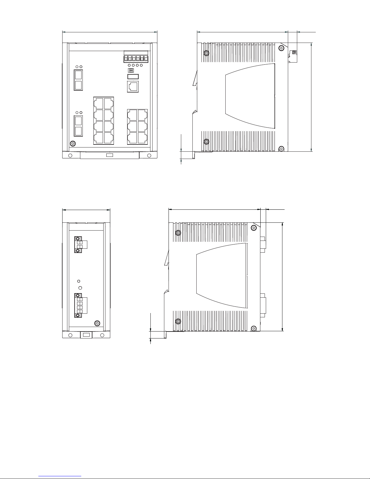
Installation RS20/22/30/32/40
Release 05 12/2015
69
Figure 25: Dimensions of device variants RS22.../RS32... with 16 to 26 ports with
operating temperature characteristic value S, T and E
Figure 26: Dimensions of RPS90/48V LV and RPS90/48V HV PoE power units
120
115
137
4.73
9
0.36
4.53
12
0.47
5.39
60
115
7,05
137
4.53 0.28
5.39
9
0.36
2.36
Page 70

70
Installation RS20/22/30/32/40
Release 05 12/2015
EMC and immunity
EMC compliance – IEC/EN 61000-6-2:2005 EMI TYPE tests,
test acc. to:
A
a)
B
a)
H
a)
IEC/EN 61000-4-2 Electrostatic discharge
Contact discharge
Air discharge
4kV
8 kV
8 kV
15 kV
8 kV
15 kV
IEC/EN 61000-4-3 Electromagnetic field
80 MHz ... 3000 MHz 10 V/m 20 V/m 20 V/m
IEC/EN 61000-4-4 Fast transients (burst)
Power line
Data line
2kV
1 kV
4kV
4kV
4kV
4kV
IEC/EN 61000-4-5 Voltage surges
Power line, line / line
Power line, line / ground
Data line
0.5 kV
1 kV
1 kV
1 kV
2kV
4kV
1 kV
2kV
4kV
IEC/EN 61000-4-6 Conducted disturbances
10 kHz - 150 kHz
150 kHz ... 80 MHz
3 V
10 V
3 V
10 V
3 V
10 V
EN 61000-4-9 Pulse magnetic fields — 300 A/m 300 A/m
EMC interference emission A
a)
B
a)
H
a)
EN 55022 Class A Yes Yes Yes
FCC 47 CFR Part 15Class A Yes Yes Yes
German Lloyd Classification + Construction Guidelines VI-
7-3 Part 1 Ed.2001
—YesYes
Stability A
a
a. Product code A: Approval = CE, UL
Product code B: Approval = CE, UL, GL, railway (along track), Sub Station, ATEX/IECEx
Produktcode H: Zulassung = CE, UL, GL, Bahn (along track), Sub Station
(See “Combination options of the device variants RS20/RS30/RS22/RS32” on page 23.
See “Combination options for the RS40 device variants” on page 26.)
B
a)
H
a)
Vibration IEC 60068-2-6 Test FC test level according
to IEC 61131-2
Yes Yes Yes
Germanischer Lloyd Guidelines for the
Performance of Type Tests Part 1
—YesYes
IEC 870-2-2 table 3 normal installation
according to EN 61850-3
—YesYes
Shock IEC 60068-2-27 Test Ea test level according
to IEC 61131-2
Yes Yes Yes
IEC 870-2-2 table 3 normal installation
according to EN 61850-3
—YesYes
Page 71

Installation RS20/22/30/32/40
Release 05 12/2015
71
Network range
Note: The line lengths specified for the transceivers apply for the
respective fiber data (fiber attenuation and BLP/dispersion).
Product
code
M-SFP-...
Wave
length
Fiber System
attenuatio
n
Example
for F/O
line length
a
a. including 3 dB system reserve when compliance with the fiber data is observed
Fiber
attenuatio
n
BLPb/
dispersion
b. Using the bandwidth length product is inappropriate for expansion calculations.
-SX/LC... MM 850 nm 50/125 µm 0-7.5 dB 0-550 m 3.0 dB/km 400 MHz×km
-SX/LC... MM 850 nm 62.5/125 µm 0-7.5 dB 0-275 m 3.2 dB/km 200 MHz×km
-MX/LC
EEC
MM 1310 nm 50/125 µm 0-12 dB 0-1.5 km 1.0 dB/km 800 MHz×km
-MX/LC
EEC
MM 1310 nm 62.5/125 µm 0-12 dB 0-500 m 1.0 dB/km 500 MHz×km
-LX/LC... MM 1310 nm
c
c. With F/O adapter compliant with IEEE 802.3-2002 clause 38 (single-mode fiber offset-
launch mode conditioning patch cord)
50/125 µm 0-10.5 dB 0-550 m 1.0 dB/km 800 MHz×km
-LX/LC... MM 1310 nm
c
62.5/125 µm 0-10.5 dB 0-550 m 1.0 dB/km 500 MHz×km
-LX/LC... SM 1310 nm 9/125 µm 0-10.5 dB 0-20 km
d
d. including 2.5 dB system reserve when compliance with the fiber data is observed
0.4 dB/km 3.5 ps/(nm×km)
LX+/LC...
SM 1310 nm 9/125 µm 5-20 dB 14-42 km 0.4 dB/km 3.5 ps/(nm×km)
-LH/LC... LH 1550 nm 9/125 µm 5-22 dB 23-80 km 0.25 dB/km 19 ps/(nm×km)
-LH+/LC LH 1550 nm 9/125 µm 15-30 dB 71-108 km 0.25 dB/km 19 ps/(nm×km)
-LH+/LC LH 1550 nm 9/125 µm 15-30 dB 71-128 km 0.21 dB/km
(typically)
19 ps/(nm×km)
Table 16: Fiber port 1000BASE-FX (SFP fiber optic Gigabit Ethernet Transceiver)
Product
code
M-SFPBIDI...
Wave
length
TX
Wave
length
RX
Fiber System
attenuat
ion
Example
for F/O
line
length
a
a. including 3 dB system reserve when compliance with the fiber data is observed
Fiber
attenuatio
n
Dispersion
Type A
LX/LC
EEC
SM 1310 nm 1550 nm 9/125 µm 0-11 dB 0-20 km 0.4 dB/km 3.5 ps/(nm×km)
Type B
LX/LC
EEC
SM 1550 nm 1310 nm 9/125 µm 0-11 dB 0-20 km 0.25 dB/km 19 ps/(nm×km)
Type A
LH/LC
EEC
LH 1490 nm 1590 nm 9/125 µm 5-24 dB 23-80 km 0.25 dB/km 19 ps/(nm×km)
Type B
LH/LC
EEC
LH 1590 nm 1490 nm 9/125 µm 5-24 dB 23-80 km 0.25 dB/km 19 ps/(nm×km)
Table 17: F/O port (bidirectional Gigabit Ethernet SFP Transceiver)
Page 72

72
Installation RS20/22/30/32/40
Release 05 12/2015
MM = Multimode, SM = Singlemode, LH = Singlemode Longhaul
Product
code
M-FASTSFP-...
Wave
length
Fiber System
attenuatio
n
Example
for F/O line
length
a
a. including 3 dB system reserve when compliance with the fiber data is observed
Fiber
attenuation
BLP/
dispersion
-MM/LC... MM 1310 nm 50/125 µm 0-8 dB 0-5 km 1.0 dB/km 800 MHz×km
-MM/LC... MM 1310 nm 62.5/125 µm 0-11 dB 0-4 km 1.0 dB/km 500 MHz×km
-SM/LC... SM 1310 nm 9/125 µm 0-13 dB 0-25 km 0.4 dB/km 3.5 ps/(nm×km)
-SM+/LC... SM 1310 nm 9/125 µm 10-29 dB 25-65 km 0.4 dB/km 3.5 ps/(nm×km)
-LH/LC... SM 1550 nm 9/125 µm 10-29 dB 47-104 km 0.25 dB/km 19 ps/(nm×km)
-LH/LC... SM 1550 nm 9/125 µm 10-29 dB 55-140 km 0.18 dB/km
b
b. with ultra-low-loss optical fiber
18 ps/(nm×km)
Table 18: Fiber port 100BASE-FX (SFP fiber optic Fast Ethernet Transceiver)
Product
code
Wave
length
Fiber System
attenuati
on
Example
for F/O line
length
a
a. including 3 dB system reserve when compliance with the fiber data is observed
Fiber
attenuation
BLP/
dispersion
-M2, -MM MM 1300 nm 50/125 µm 0-8 dB 0-5 km 1.0 dB/km 800 MHz×km
-M2, -MM MM 1300 nm 62.5/125 µm 0-11 dB 0-4 km 1.0 dB/km 500 MHz×km
-M4, -NN SM 1300 nm 62.5/125 um 0-11 dB 0-4 km 1.0 db/km 500 MHz×km
-S2, -VV SM 1300 nm 9/125 µm 0-16 dB 0-30 km 0.4 dB/km 3.5 ps/(nm×km)
-S4, -UU SM 1300 nm 9/125 um 0-16 db 0-30 km 0.4 db/km 3.5 ps/(nm×km)
-E2, EE SM+ 1300 nm 9/125 µm 7-29 dB 20-65 km 0.4 dB/km 3.5 ps/(nm×km)
-L2, -LL LH 1550 nm 9/125 µm 7-29 dB 24-86 km 0.3 dB/km 19 ps/(nm×km)
-G2, -GG LH+ 1550 nm 9/125 µm 14-47 dB 67-176 km 0.25 dB/km 19 ps/(nm×km)
Table 19: F/O port 100BASE-FX
10/100/1000 Mbit/s twisted pair port
Length of a twisted pair segment max. 100 m (for cat5e cable)
Page 73

Installation RS20/22/30/32/40
Release 05 12/2015
73
Power consumption/power output
Device name Device model Maximum
power
consumption
Power output
2 uplink ports:
RS20-0400... 2xTX port 5.3 W 18.1 Btu (IT)/h
RS20-0400... 1xFX port, 1xTX port 6.5 W 22.2 Btu (IT)/h
RS20-0400... 2xFX port 7.7 W 26.3 Btu (IT)/h
RS20-0800... RS22-0800... 2xTX port 5.3 W 18.1 Btu (IT)/h
RS20-0800... RS22-0800... 1xFX port, 1xTX port 6.5 W 22.2 Btu (IT)/h
RS20-0800... RS22-0800... 2xFX port 7.7 W 26.3 Btu (IT)/h
RS20-1600... RS22-1600... 2xTX port 9.4 W 32.1 Btu (IT)/h
RS20-1600... RS22-1600... 1xFX port, 1xTX port 10.6 W 36.2 Btu (IT)/h
RS20-1600... RS22-1600... 2xFX port 11.8 W 40.3 Btu (IT)/h
RS20-2400-... RS22-2400-... 2xTX port 12.1 W 41.3 Btu (IT)/h
RS20-2400-... RS22-2400-... 1xFX port, 1xTX port 13.3 W 45.4 Btu (IT)/h
RS20-2400-... RS22-2400-... 2xFX port 14.5 W 52.9 Btu (IT)/h
RS30-0802-... RS32-0802-... 2xTX port 8.9 W 30.4 Btu (IT)/h
RS30-0802-... RS32-0802-... 1xFX port, 1xTX port 8.6 W 29.4 Btu (IT)/h
RS30-0802-... RS32-0802-... 2xFX port 8.3 W 28.4 Btu (IT)/h
RS30-1602-... RS32-1602-... 2xTX port 13.0 W 44.4 Btu (IT)/h
RS30-1602-... RS32-1602-... 1xFX port, 1xTX port 12.7 W 43.4 Btu (IT)/h
RS30-1602-... RS32-1602-... 2xFX port 12.4 W 42.4 Btu (IT)/h
RS30-2402-... RS32-2402-... 2xTX port 15.7 W 53.6 Btu (IT)/h
RS30-2402-... RS32-2402-... 1xFX port, 1xTX port 15.4 W 52.6 Btu (IT)/h
RS30-2402-... RS32-2402-... 2xFX port 15.1 W 51.6 Btu (IT)/h
3 uplink ports:
RS20-0900-... RS22-0900-... 3xFX port 9.6 W 32.8 Btu (IT)/h
RS20-1700-... RS22-1700-... 3xFX port 13.7 W 46.7 Btu (IT)/h
RS20-2500-... RS22-2500-... 3xFX port 16.4 W 56.0 Btu (IT)/h
4 uplink ports:
RS30-0802-... RS32-0802-... 4xFX port 12.7 W 43.3 Btu (IT)/h
RS30-1602-... RS32-1602-... 4xFX port 16.8 W 57.3 Btu (IT)/h
RS30-2402-... RS32-2402-... 4xFX port 19.5 W 66.5 Btu (IT)/h
RS40-... 4xFX port 20.0 W 68.2 Btu (IT)/h
Table 20: Power consumption/power output RS20/RS30/RS40 and RS22/RS32
without PDs (powered devices)
Device name Device model Maximum
power
consumption
Power output
2 uplink ports:
RS22-0800... 2xTX port 70.9 W 31.8 Btu (IT)/h
RS22-0800... 1xFX port, 1xTX port 72.1 W 35.9 Btu (IT)/h
Table 21: Power consumption/power output RS22/RS32 with 4 x Class0 PD
(powered device)
Page 74

74
Installation RS20/22/30/32/40
Release 05 12/2015
Scope of delivery
RS22-0800... 2xFX port 73.3 W 40.0 Btu (IT)/h
RS22-1600... 2xTX port 75.0 W 45.8 Btu (IT)/h
RS22-1600... 1xFX port, 1xTX port 76.2 W 49.9 Btu (IT)/h
RS22-1600... 2xFX port 77.4 W 54.0 Btu (IT)/h
RS22-2400-... 2xTX port 77.7 W 55.0 Btu (IT)/h
RS22-2400-... 1xFX port, 1xTX port 78.9 W 59.1 Btu (IT)/h
RS22-2400-... 2xFX port 80.1 W 66.6 Btu (IT)/h
RS32-0802-... 2xTX port 74.5 W 44.1 Btu (IT)/h
RS32-0802-... 1xFX port, 1xTX port 74.2 W 43.1 Btu (IT)/h
RS32-0802-... 2xFX port 73.9 W 42.1 Btu (IT)/h
RS32-1602-... 2xTX port 78.6 W 58.1 Btu (IT)/h
RS32-1602-... 1xFX port, 1xTX port 78.3 W 57.1 Btu (IT)/h
RS32-1602-... 2xFX port 78.0 W 56.1 Btu (IT)/h
RS32-2402-... 2xTX port 81.3 W 67.3 Btu (IT)/h
RS32-2402-... 1xFX port, 1xTX port 81.0 W 66.3 Btu (IT)/h
RS32-2402-... 2xFX port 80.7 W 65.3 Btu (IT)/h
3 uplink ports:
RS22-0900-... 3xFX port 75.2 W 46.5 Btu (IT)/h
RS22-1700-... 3xFX port 79.3 W 60.4 Btu (IT)/h
RS22-2500-... 3xFX port 82.0 W 69.7 Btu (IT)/h
4 uplink ports:
RS32-0802-... 4xFX port 78.3 W 57.0 Btu (IT)/h
RS32-1602-... 4xFX port 82.4 W 71.0 Btu (IT)/h
RS32-2402-... 4xFX port 85.1 W 80.2 Btu (IT)/h
Device Scope of delivery
RS20-..., RS30-..., RS40-...,
RS22-... or RS32-...
Device
Terminal block for supply voltage and signal contact
Installation user manual and CD/DVD
RS22-16..., RS22-17...,
RS22-24..., RS22-25...
Additionally: ferrite with key
Device name Device model Maximum
power
consumption
Power output
Table 21: Power consumption/power output RS22/RS32 with 4 x Class0 PD
(powered device)
Page 75

Installation RS20/22/30/32/40
Release 05 12/2015
75
Order numbers/product description
The order numbers correspond to the product codes of the devices.
See “Combination options of the device variants
RS20/RS30/RS22/RS32” on page 23.
See “Combination options for the RS40 device variants” on page 26.
Accessories
Note that products recommended as accessories may have different
characteristics to those of the device, which may limit the application
range of the overall system. For example, if you add an accessory with IP
20 to a device with IP 65, the IP of the overall system is reduced to 20.
Gigabit Ethernet SFP transceiver Order number
M-SFP-TX/RJ45 943 977-001
The following operating conditions apply to twisted pair transceivers:
Usable with:
- HiOS as of software version 03.0.00
- Classic Switch software, as of software version 04.1.00.
- HiSecOS as of software version 01.2.00
Do not use with the following devices:
- SPIDER II
- MSP/MSM
- EES
Longer RSTP switching times and link loss detection times compared to twisted pair ports
provided by the device directly.
Not applicable for combo and Fast Ethernet ports.
Only support of the autonegotiation mode including autocrossing.
M-SFP-SX/LC 943 014-001
M-SFP-SX/LC EEC 943 896-001
M-SFP-MX/LC EEC 942 108-001
M-SFP-LX/LC 943 015-001
M-SFP-LX/LC EEC 943 897-001
M-SFP-LX+/LC 942 023-001
M-SFP-LX+/ LC EEC 942 024-001
M-SFP-LH/LC 943 042-001
M-SFP-LH/LC EEC 943 898-001
M-SFP-LH+/LC 943 049-001
Bidirectional Gigabit Ethernet SFP transceiver Order number
M-SFP-BIDI Type A LX/LC EEC 943 974-001
M-SFP-BIDI Type B LX/LC EEC 943 974-002
M-SFP-BIDI Type A LH/LC EEC 943 975-001
M-SFP-BIDI Type B LH/LC EEC 943 975-002
M-SFP-BIDI Bundle LX/LC EEC (type A + B) 943 974-101
M-SFP-BIDI Bundle LH/LC EEC (type A + B) 943 975-101
Page 76

76
Installation RS20/22/30/32/40
Release 05 12/2015
Fast Ethernet SFP transceiver Order number
M-FAST SFP-TX/RJ45 942 098-001
M-FAST SFP-TX/RJ45 EEC 942 098-002
The following operating conditions apply to twisted pair transceivers:
Usable with:
- HiOS as of software version 03.0.00
- for PRP ports on RSP devices, as of software version 02.0.01
- for PRP ports on EES devices, as of software version 02.0.02
- Classic switch software as of software version 08.0.00
- HiSecOS ab Software-Version 01.2.00
Longer RSTP switching times and link loss detection times compared to twisted pair ports
provided by the device directly.
Not applicable for combo ports.
Not applicable for ports which support only Gigabit Ethernet.
To set autocrossing manually is currently not possible.
M-FAST SFP-MM/LC 943 865-001
M-FAST SFP-MM/LC EEC 943 945-001
M-FAST SFP-SM/LC 943 866-001
M-FAST SFP-SM/LC EEC 943 946-001
M-FAST SFP-SM+/LC 943 867-001
M-FAST SFP-SM+/LC EEC 943 947-001
M-FAST SFP-LH/LC 943 868-001
M-FAST SFP-LH/LC EEC 943 948-001
Special accessories for the device variants RS22/RS32 Order number
Wall mounting plate in DIN rail design, width 4.72 in. (120 mm) 943 971-001
Wall mounting plate for DIN rail mounting, width 3.54 in. (90 mm) 943 971-002
RPS 90/48V HV (high-voltage) PoE power unit 943 979-001
RPS 90/48V HV (high-voltage) PoE power unit with conformal coating 943 979-101
RPS 90/48V LV (low-voltage) PoE power unit 943 980-001
RPS 90/48V LV (low-voltage) PoE power unit with conformal coating 943 980-101
Other accessories Order number
AutoConfiguration Adapter ACA21-USB (EEC) 943 271-003
Terminal cable 943 301-001
6-pin terminal block (50 pcs.) 943 845-006
Rail Power Supply RPS 30 943 662-003
Rail Power Supply RPS 80 EEC 943 662-080
Rail Power Supply RPS 120 EEC (CC) 943 662-121
Industrial HiVision Network Management Software 943 156-xxx
OPC server software HiOPC 943 055-001
Page 77

Installation RS20/22/30/32/40
Release 05 12/2015
77
Underlying technical standards
The device has an approval based on a specific standard only if the
approval indicator appears on the device casing.
If your device has a shipping approval according to Germanischer Lloyd,
you find the approval mark printed on the device label. You will find out
whether your device has other shipping approvals on the Hirschmann
website under www.hirschmann.com in the product information.
The device generally fulfills the technical standards named in their current
versions.
Name
CSA C22.2 No. 213 Canadian National Standard(s) for Nonincendive Electrical
Equipment for Use in Class I, Division 2 Hazardous Locations
EN 50121-4 Railway applications - EMC - emitted interference and interference
immunity for signal and telecommunication systems
EN 55022 Information technology equipment – Radio disturbance
characteristics – Limits and methods of measurement
IEC/EN 60079-15 Explosive atmospheres – Part 15: Equipment protection by type of
protection “n”
EN 60950-1 Information technology equipment – Safety – Part 1: General
requirements
EN 61000-6-2 Electromagnetic compatibility (EMC) – Part 6-2: Generic standards
– Immunity for industrial environments
EN 61131-2 Programmable controllers – Part 2: Equipment requirements and
tests
FCC 47 CFR Part 15 Code of Federal Regulations
Germanischer Lloyd Rules for Classification and Construction VI-7-2 – GL
IEC/EN 61850-3 Communication networks and systems in substations – Part 3:
General requirements
IEEE 802.1 D Switching, GARP, GMRP, Spanning Tree
IEEE 802.1 D Media access control (MAC) bridges (includes IEEE 802.1p
Priority and Dynamic Multicast Filtering, GARP, GMRP)
IEEE 802.1Q Virtual LANs (VLANs, MRP, Spanning Tree)
IEEE 802.1 Q Virtual Bridged Local Area Networks (VLAN Tagging, GVRP)
IEEE 802.1w Rapid Reconfiguration
IEEE 802.3 Ethernet
IEEE 1613 IEEE Standard Environmental and Testing Requirements for
Communication Networking Devices in Electric Power Substations
Korean Register of
Shipping
Rules for the Classification of Steel Ships – KR
UL 508 Safety for Industrial Control Equipment
Table 22: List of the technical standards
Page 78

78
Installation RS20/22/30/32/40
Release 05 12/2015
A Further Support
Technical Questions
For technical questions, please contact any Hirschmann dealer in your
area or Hirschmann directly.
You will find the addresses of our partners on the Internet at
http://www.hirschmann.com
Contact our support at
https://hirschmann-support.belden.eu.com
You can contact us
in the EMEA region at
Tel.: +49 (0)1805 14-1538
E-mail: [email protected]
in the America region at
Tel.: +1 (717) 217-2270
E-mail: [email protected]
in the Asia-Pacific region at
Tel.: +65 6854 9860
E-mail: [email protected]
Hirschmann Competence Center
The Hirschmann Competence Center is ahead of its competitors:
Consulting incorporates comprehensive technical advice, from system
evaluation through network planning to project planning.
Training offers you an introduction to the basics, product briefing and
user training with certification.
The current technology and product training courses can be found at
http://www.hicomcenter.com
Support ranges from the first installation through the standby service
to maintenance concepts.
With the Hirschmann Competence Center, you have decided against
making any compromises. Our client-customized package leaves you
free to choose the service components you want to use.
Internet:
http://www.hicomcenter.com
Page 79

Installation RS20/22/30/32/40
Release 05 12/2015
79
Page 80

 Loading...