

Hirschmann RS1-FX/FX, RS1-TX/TX, RS1-TX/FX, RS1-TX/FX-SM, RM1 Description And Operating Instructions
Page 1
1
Description and operating instructions
i Rail Switch Family
The i Rail Switch modules allow
switched Ethernet networks in accordance
with IEEE standard 802.3 using copper technology and backbones in accordance with
IEEE standard 802.3u using copper technology or optical waveguide (F/O) in line and
ring structure to be constructed. The switch
modules are plugged onto the standard bar.
The RS1s (Rail Switch) have eight 10 Mbit/s
twisted pair (TP) ports and two 100 Mbit/s
ports. Depending on the type of RS1 the
100 Mbit/s ports to attach further more RS1
are supplied with FX, TX interfaces or both.
It is possible to connect up to eight pieces
of terminal equipment or other TP segments to the 10 Mbit/s ports using TPs.
The built-in control intelligence allows the
redundant coupling of several network segments to a higher network segment.
An RM1 (Redundancy Manager) has eight
10 Mbit/s TP ports and two free slots for
100 Mbit/s modules. The 100 Mbit/s ports
allow to close a line-structured backbone to
a ring with redundancy function.
The 100 Mbit/s module ETSXM-01TP(FE)
has one TX port.
The 100 Mbit/s module ETSXM-01MM(FE)
has one FX port.
P1 123456879
10
DA / STAT
P2
FDX
Port 1 - 4
Stby
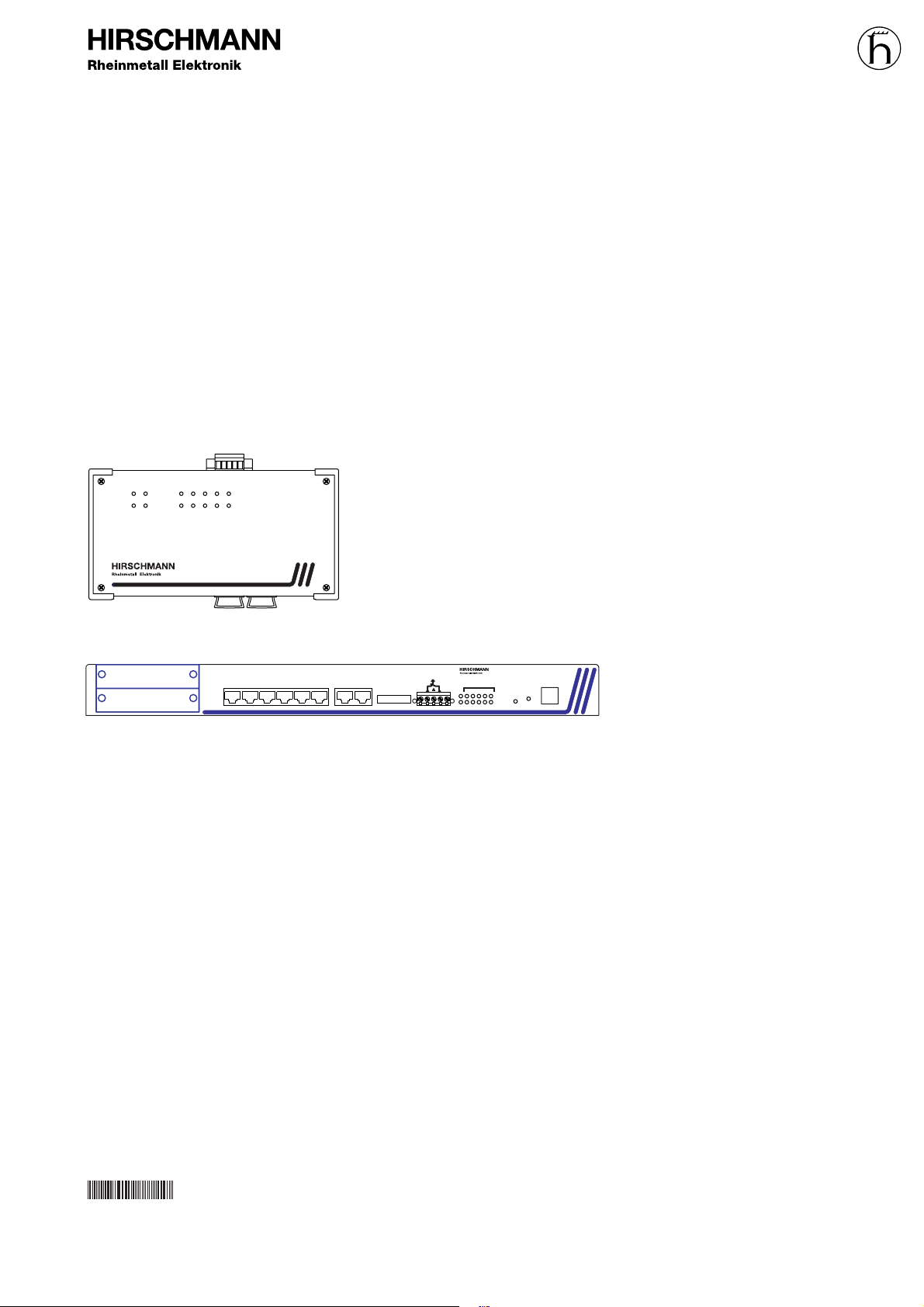
Rail Switch RS1-FX/FX
i
CPU RESET V24
+24 V +24 V*
Fault
Redundancy Manager RM1
DA/STAT
Port
P113579
246810P2
LA1
LA2
LA3
LA4
LA5
0
1
LA6
LA7
LA8
LA9
LA10
9
10
1234
758
6
RS1-…
Order no.
943 606-0…
RM1
Order no.
943 632-001
039587001010998000
Printed in Germany
Page 2

2
Safety guidelines
v
Warning!
The RS1/RM1 units are designed for
operation with safety extra-low voltage. Accordingly, only safety extralow voltages (SELV) to
IEC950/EN60950/VDE0805 may be
connected to the supply voltage
connections.
ESD protection
The 100 Mbit/s modules contain components highly sensitive to electrostatic fields.
These components can be easily destroyed
or have their lives shortened by an electrical
field or by a discharge caused by touching
the card.
For these reasons, the 100 Mbit/s modules
are delivered in a conducting ESD protective bag. This packing can be reused.
Be sure to observe the following precautions for electrostatic sensitive devices when
handling the components:
M Establish electrical potential equality between yourself and your surroundings, e.g.
with the aid of a wrist bracelet.
M Only then remove the 100 Mbit/s modules from the conducting bag.
M Store the 100 Mbit/s modules in its conducting bag whenever it is not in the chassis.
ESD protective field kits are available for
working with electrostatic sensitive devices.
You can find more information about devices vulnerable to electrostatic fields in
DIN/IEC 47 (Sec) 1330; February 1994 Edition and DIN EN 100 015.
We have checked that the contents of the
technical publication agree with the hardware and software described. However, it is
not possible to rule out deviations completely, so we are unable to guarantee complete agreement. However, the details in the
technical publication are checked regularly.
Any corrections which prove necessary are
contained in subsequent editions. We are
grateful for suggestions for improvement.
We reserve the right to make technical
modifications.
Permission is not given for the circulation
or reproduction of this document, its use or
the passing on of its contents unless granted expressly. Contravention renders the
perpetrator liable for compensation for
damages. All rights reserved, in particular
in the case of patent grant or registration of
a utility or design.
Copyright ©
© Richard Hirschmann GmbH & Co. 1998
All Rights Reserved
General
Electricity is used to operate this equipment. Comply in every detail with the safety
requirements specified in the operating
instructions regarding the voltages to
apply!
v
Warning!
If warning notes are ignored, it is
therefore possible for severe injuries
and/or material damage to occur.
Only appropriately qualified staff
should work on or near this equipment. Such staff must be thoroughly
acquainted with all the warnings
and maintenance measures contained in these operating instructions.
The proper and safe operation of
this equipment assumes proper
transport, appropriate storage and
assembly and careful operation and
maintenance.
Staff qualification
requirements
Qualified staff within the meaning of these
operating instructions or the warning notes
are persons familiar with setting up, assembling, starting up and operating this product
and who have appropriate qualifications to
cover their activities, such as:
– training or instruction/entitlement to
switch circuits and equipment/systems on
and off, earth them and identify them in
accordance with current safety standards;
– training or instruction in accordance with
current safety standards in looking after
and using appropriate safety equipment;
– first aid training.
Page 3
3
1. Functional description
The ports of an RS1/RM1 represent a terminal connection for the connected LAN segment.
1.1 FRAME-SWITCHING FUNCTIONS
Store and Forward
All data received by the RS1/RM1 from the
system bus or at the ports are stored and
checked for validity. Invalid and defective
frames as well as fragments are discarded.
The RS1/RM1 forwards the valid frames.
Multi address capability
An RS1 learns all source addresses per port.
Only packets with
– this address or
– a multi/broadcast address
in the destination address field are sent to
this port.
An RS1 learns up to 8.000 addresses. This
becomes necessary if more than one terminal device is connected to one or more
ports. In this way several independent subnetworks can be connected to an RS1.
Learn addresses
An RS1 monitors the age of the learned
addresses. The RS1 deletes address entries
from the address table which exceed a certain age (10 seconds).
Note: Restarting deletes the learned
address entries.
Operation in duplex mode
Depending on the DIP switch setting of the
RS1 the 10 MBit/s ports 1 to 4 are in the half
or fullduplex mode. The 10 Mbit/s ports 5 to
8 are in the halfduplex mode.
Each 100 Mbit/s port is in the fullduplex
mode.
1.2 SPECIFIC FUNCTIONS OF THE
TP INTERFACE
Link control
The RS1/RM1 monitors the connected TP
line segments for short-circuit or interrupt
using regular link test pulses in accordance
with IEEE standard 802.3 10BASE-T. The
RS1/RM1 does not transmit any data in an
TP segment from which it does not receive
a link test pulse.
Note: A non-occupied interface is assessed
as a line interrupt. The TP line to terminal
equipment which is switched off is likewise
assessed as a line interrupt as the deenergised bus coupler cannot transmit link
test pulses.
Auto polarity exchange
If the reception line pair is incorrectly
connected (RD+ and RD- switched) polarity
is automatically reversed.
1.3 SPECIFIC FUNCTIONS OF THE
F/O INTERFACE
Link control
According to IEEE 802.3 standard 100BASEFX an RS1/RM1 monitors the attached F/O
lines for open circuit conditions.
1.4 REDUNDANCY FUNCTIONS
Backbone as a ring
With an RM1 you can close a line structured
RS1 backbone to a redundant ring.
If one section fails the ring structure changes itself back into a line structure within
0.5 seconds at up to 50 RS1s.
Redundant coupling of segments
The built-in control intelligence of the RS1s
allows the redundant coupling of 10 MBit/s
network segments. Within 0.5 seconds an
error is detected and eliminated.
1.5 DISPLAY ELEMENTS
Equipment status
These LEDs provide information about statuses which affect the function of the entire
RS1/RM1s.
L1 – Line 1 (green LED)
– lit: – supply voltage 1 present
– lit not: – supply voltage 1 is less than 18 V,
– hardware fault in RS1/RM1
L2 – Line 2 (green LED)
– lit: – supply voltage 2 present
– lit not: – supply voltage 2 is less than 18 V,
– hardware fault in RS1/RM1
FDX – Fullduplex (Green LED, RS1)
– lit: – Full duplex mode
(10 MBit/s ports 1 to 4).
– lit not: – Half duplex mode
(10 MBit/s ports).
Stby – Standby (Green LED, RS1)
– lit: – The standby function is
enabled.
– lit not: – The standby function is
disabled.
CPU – System (Yellow/red LED, RM1)
– lit not: – Initializing, hardware self
test
– lit red: – Self test error
– flashes red (1 Hz):
– Loading software
– lit red with interruption:
– Writing to Flash EPROM
– lit yellow: – The User Interface (V.24)
is occupied
– flashes yellow (0,5 Hz):
– The system is initialized
and runs fault-free.
Port Status
These LEDs display port-related information.
DA/STAT – Data, Link status
(green/yellow LED)
– lit not: – no valid link
– lit green: – valid link
– blinking green (1 time in periodical inter-
val)
– port is switched to stand-
by (RS1, port 1, 2)
– blinking green (2 times in periodical inter-
val)
– port is autopartitioned
– blinking green (3 times in periodical inter-
val)
– port is disabled
– flashes yellow:– receiving data
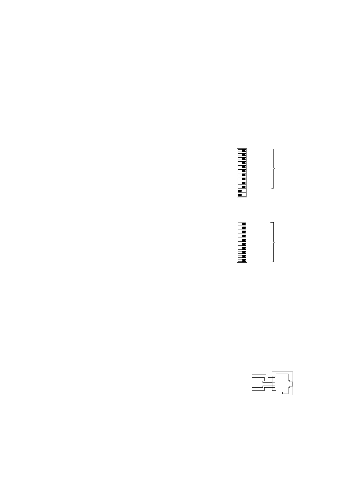
1.6 CONTROLS
12-pin DIP switch (RS1)
10-pin DIP switch (RM1)
Using the 12-pin DIP switch on the top of
the RS1 housing and the 10-pin DIP switch
on the front panel of the RM1 housing
– the message about the link statuses can
be suppressed by the indicator contact on
a port-by-port basis. Using switches LA1
to LA6, the message about the link status
of ports 1 to 6 is suppressed. State on
delivery: switch position 1 (on), i.e. message not suppressed.
– on RS1 the 10 MBit/s ports 1 to 4 can be
switched to the full duplex or half duplex
mode with the switch FDX. State of delivery: position 0 (Off), i.e. half duplex.
The 10 Mbit/s ports 5 to 8 are always in
the halfduplex mode.
– on RS1 the standby function can be enab-
led or disabled with the switch Stby .
State of delivery: position 0 (Off), i.e. normal function. In the redundant link run the
RS1 in the standby mode for redundant
coupling of 10 MBit/s network segments.
RS1 in the standby mode for redundant
coupling of 10 MBit/s network segments.
Fig. 1: 12-pin DIP switch on RS1
Fig. 2: 10-pin DIP switch on RS1
Reset push button (RM1)
Pushing the push button resets the RM1.
1.7 INTERFACES
10 Mbit/s connection
Eight 8-pin RJ45 sockets allow eight independent TP segments to be connected. The
socket casings are electrically connected to
the front panel and thus connected to the
housing of the RS1/RM1.
– Pin configuration of the RJ45 socket:
– TD+: pin 3, TD-: pin 6
– RD+: pin 1, RD-: pin 2
– remaining pins: not configured.
Fig. 3: Pin configuration of an TP interface
n.c. Pin 8
n.c. Pin 7
TD- Pin 6
n.c. Pin 5
n.c. Pin 4
Pin 3TD+
Pin 2RDPin 1RD+
LA1
LA6
Off On
LA5
LA3
LA2
LA4
Port 1
Port 6
Port 5
Port 3
Port 2
Port 4
Suppress message
about link status
via indicator contact
LA10
LA9
LA7
LA8
Port 10
Port 9
Port 7
Port 8
LA1
LA6
Off On
LA5
LA3
LA2
LA4
Port 1
Port 6
Port 5
Port 3
Port 2
Port 4
Suppress message
about link status
via indicator contact
Stby
FDX
Redundancy mode
Full Duplex
LA10
LA9
LA7
LA8
Port 10
Port 9
Port 7
Port 8
Page 4

4
supply voltage is electrically isolated from
the housing.
– Indicator contact: Contract interrupt
indicates the following by means of a
potential-free indicator contact (relay
contact, closed circuit):
– the failure of at least one of the two
supply voltages.
– a permanent fault in the RS1/RM1 (inter-
nal 5 V DC voltage, supply voltage 1 or 2
< 18 V).
– the faulty link status of at least one port.
The indication of the link state might be
masked on a port-by-port basis using
DIP switches (RS1).
– at least one port has auto partitioned.
– selft test error
RM1
– Ring monitoring is not possible, e. g.
during software initializing.
RS1 in normal mode
– short-circuited control line.
– partner device runs in normal mode.
RS1 in standby mode
– not attached, short-circuited or interrup-
ted control line.
– partner device runs in normal mode.
Note: In the case of the voltage supply
being routed without redundancy, the
RS1/RM1 indicates the failure of a supply
voltage. You can prevent this message by
feeding in the supply voltage through both
inputs.
Fig. 5: Pin configuration of 5-pin terminal
block
+24 V
+24 V
Fault
L1+
L2+
M
F1
F2
100 Mbit/s connection
Two ports allow a 100 Mbit/s backbone to
be constructed.
– RS1-FX/FX: two ports in accordance with
100BASE-FX (SC sockets, multimode)
– RS1-TX/TX: two ports in accordance with
100BASE-TX (RJ45 sockets)
– RS1-TX/FX: one port in accordance with
100BASE-FX (SC socket, multimode) and
one port in accordance with 100BASE-TX
(RJ45 socket)
– RS1-TX/FX: one port in accordance with
100BASE-FX (SC socket, singlemode) and
one port in accordance with 100BASE-T
(RJ45 socket)
– RM1: two slots for 100 Mbit/s modules
with one port each:
ETSXM-01TP(FE) with TX port,
ETSXM-01MM(FE) with one FX port
Standby-Port (RS1)
A 8-pin RJ45 socket serves for connecting
the control line for the redundancy mode.
The socket casing is electrically connected
to the front panel and thus connected to the
housing of the RS1s.
– Pin configuration of the RJ45 socket:
– Stby_Out+: Pin 3, Stby_Out-: Pin 6
– Stby_In+: Pin 1, Stby_In-: Pin 2
– remaining pins: not configured.
Fig. 4: Pin configuration of the standby
interface
5-pin terminal block
The supply voltage and the indicator
contact are connected via a 5-pin terminal
block with screw locking mechanism.
v
Warning!
The RS1/RM1 equipment is designed for operation with SELV. Only
safety extra-low voltages to
IEC950/EN60950/VDE0805 may
therefore be connected to the
supply voltage connections and to
the indicator contact.
– Voltage supply: The voltage supply can
be connected to be redundant. Both
inputs are decoupled. There is no load
distribution. With redundant supply, the
power pack supplies the RS1/RM1 alone
with the higher output voltage. The
n.c. Pin 8
n.c. Pin 7
Stby_Out- Pin 6
n.c. Pin 5
n.c. Pin 4
Pin 3Stby_Out+
Pin 2Stby_InPin 1Stby_In+
2. Configuration
2.1 LINE STRUCTURE
The RS1s enable backbones in line structures to be built up. Cascading is effected
using the 100 Mbit/s ports (see Fig. 5).
2.2 REDUNDANT RING STRUCTURE
With an RM1 you can close the two ends of
a line structured backbone to a redundant
ring (see Fig. 6)
2.3 REDUNDANT COUPLING OF NETWORK SEGMENTS
The built-in control intelligence of the RS1
allows the redundant coupling of network
segments (see Fig. 7).
The connection of two network segments is
realized via two seperate paths with an RS1
each. The RS1 in the redundant line gets the
redundancy function assigned by the DIP
switch setting standby.
The RS1 in the redundant line and the RS1
in the main line share their operating states
via the control line.
After the failure of the main line the redundant RS1 enables the redundant line immediately. If the main line is okay again, the
RS1 in the main line informs the redundant
RS1 about this. The main line will be enabled and the redundant line will be disabled.
…
RS1 RS1 RS1 RS1 RS1 RS1
Fig. 6: Line structure
Page 5

5
RM1
RS1 RS1 RS1 RS1 RS1 RS1
RS1RS1RS1RS1RS1RS1
Fig. 7: Redundant ring structure
redundante
coupling
Ring 1 <–> Ring 2
OTP OTP
OTP OTP
OTP
RM1
control line
control line
RM1
Ring 1
Ring 2
Ring 3
redundante
coupling
Ring 1 <–> Ring 3
For coupling network segments the ports 1 and 2
are to use on these RS1.
All other ports must stay free.
For coupling network segments the ports 1 or 2
are to use on these RS1.
OTP OTP OTP
RS1RS1
RS1
RS1
RS1RS1RS1
RS1
RS1RS1RS1
RS1 RS1 RS1 RS1 RS1 RS1
RS1
RS1 RS1
Fig. 8: Redundant coupling of rings
Page 6

6
3. Assembly, startup procedure
and dismantling
3.1 UNPACKING, CHECKING
M Check whether the package was delivered complete (see scope of delivery).
M Check the individual parts for transport
damage.
v
Warning!
Use only undamaged parts!
3.2 ASSEMBLY
The equipment is delivered in a ready-tooperate condition. The following procedure
is appropriate for assembly:
RS1
M Check whether the switch pre-setting
suits your requirements (see chap. 1.6).
M Pull the terminal block off the RS1 and
wire up the supply voltage and indicator
lines.
M Fit the RS1 on a 35 mm standard bar to
DIN EN 50 022.
M Suspend the upper snap-on slide bar of
the RS1 in the standard bar and press it
down towards the standard bar until it locks
in position.
M Fit the signal lines and if required the
control line.
Notes:
– The housing of the RS1 is grounded via
the standard bar. There is no separate
ground connection.
– Do not open the housing.
– The shielding ground of the twisted pair
lines which can be connected is electrical-
ly connected to the housing.
Fig. 9: Assambling the RS1
RM1
m Mounting the rubber feet
Stick the rubber feet supplied to the bottom
of the device in order to set it up as a desktop unit.
M Remove the backing from the adhesive
film of the rubber feet.
M Stick one rubber foot approx. 2 cm from
each corner of the device.
Note: The surface should be free of dust
and grease.
m Screwing on the mounting brackets
M Attach the mounting brackets supplied
as shown in Fig. 10:
M First loosen the four corresponding
screws on one side of the device
M Attach the first mounting bracket with
the 4 screws.
M Repeat on the other side.
Fig. 10: Fastening the mounting brackets
m Grounding the RM1´s
The housing of the RM1 is grounded via the
sperate grounding screw. It is on the device
back on the right next to the fan.
M Fasten the grounding cable on the
grounding screw.
m Fitting with 100 Mbit/s modules
The modules can be plugged in and pulled
off the RM1 during operation (hot swapable).
M Be sure to observe the notes on ESD
protection on page 2.
M Choose a slot.
M Remove the blind panel of the RM1 so
that you are able to plug in the module.
M Push the module in the slot’s mounting
rails on the right and left side well fitting as
far as it will go.
M Screw
– the two thumbscrews in the
front panel of the module with
– the frame of the RM1.
m Connecting the RM1
M Check whether the switch pre-setting
suits your requirements (see chap. 1.6).
M Pull the terminal block off the RM1 and
wire up the supply voltage and indicator
lines.
M Fit the signal lines.
3.3 STARTUP PROCEDURE
You start up the RS1/RM1 by connecting the
supply voltage via the 5-pin terminal block.
Lock the terminal block with the locking
screw at the side.
3.4 DISMANTLING
To dismantle the RS1 from the standard bar,
pull the RS1 downwards and on the bottom
lift the RS1 away from the standard bar.
Mounting brackets
Mounting in 19" cabinet
4. Further support
In the event of technical queries, please talk
to the Hirschmann contract partner responsible for looking after you or directly to the
Hirschmann office. You can find the addresses of our contract partners
– on the Internet
(http://www.hirschmann.de).
Our hotline is also at your disposal:
Tel. +49(7127) 14-1538 (Fax -1542)
Page 7

7
5. Technical data
General data
Operating voltage DC 18 to 32 V safety extra-low voltage (SELV) (redundant inputs decoupled)
Current consumption 500 mA (RS1) and 1.2A (RM1) respectively maximum, at 24 VDC
Overload current protection at input non-changeable thermal fuse
Dimensions W x H x D 210 mm x 125 mm x 85 mm (RS1) and 434 mm x 44 mm x 279 mm (RM1) respectively
8,3 in x 4,9 in x 3,3 in (RS1) and 17,1 in x 1,7 in x 11 in (RM1) respectively
Mass RS1 1,36 kg (3,0 lb), RM1 3,5 kg (7,7 lb)
Ambient temperature 0 ºC to + 60 ºC (RS1) and 0 ºC to + 40 ºC (RM1) respectively
Storage temperature - 40 ºC to + 80 ºC
Humidity 10% to 90% (not-condensing)
Protection class IP 20 (RS1), IP 30 (RM1)
Radio interference level EN 55022 Class B
Interference immunity EN 50082-2
Network size
TP port 10BASE-T
Length of a twisted pair segment 100 m (328 ft) maximum
TP port 100BASE-TX (ETSXM-01TP(FE), RS1-TX/TX and RS1-TX/FX)
Length of a twisted pair segment 100 m (328 ft) maximum
F/O port 100BASE-FX (ETSXM-01MM(FE), RS1-FX/FX und RS1-TX/FX)
According to IEEE 802.3u 100BASE-FX
System attenuation
50/125 µm fiber 8 dB
62,5/125 µm fiber 11 dB
10/125 µm fiber 11 dB
Wave length 1300 nm
F/O line length (example)
50/125 µm fiber 3000 m (9843 ft) maximum (data of fiber: 1,6 dB/km, 500 Mhz*km)
62,5/125 µm fiber 3000 m (9843 ft) maximum (data of fiber: 2,6 dB/km, 500 Mhz*km)
10/125 µm fiber 40 km (131.234 ft) maximum (data of fiber: 0,2 dB/km)
Scope of delivery
Rail Switch RS1 incl.
terminal block for supply voltage
description and operating instructions
Redundancy Manager RM1 incl.
terminal block for supply voltage
description and operating instructions
4 rubber feet (RM1)
1 pair mounting brackets (RM1)
Order number
Rail Switch RS1-FX/FX 943 606-031
Rail Switch RS1-TX/TX 943 606-001
Rail Switch RS1-TX/FX 943 606-032
Rail Switch RS1-TX/FX-SM 943 606-033
Redundancy Manager RM1 943 632-001
Accessories
Ethernet manual 943 320-011
100BASE-X-Module
ETSXM01TP(FE) 943 567-001
ETSXM01MM(FE) 943568-001
Page 8

8
Notes on CE identification
The link modules for Industrial
Ethernet comply with the regulations of the following European
directive:
89/336/EEC
Council Directive on the harmonisation of the legal regulations of
member states on electromagnetic
compatibility (amended by Directives 91/263/EEC, 92/31/EEC and
93/68/EEC).
Area used Requirements for
emitted interference interference immunity
Residential EN 50081-1: 1992 EN 50082-1: 1997
Industrial EN 50081-2: 1995 EN 50082-2: 1995
The product can be used in the residential
sphere (residential sphere, business and
trade sphere and small companies) and in
the industrial sphere.
The precondition for compliance with EMC
limit values is strict adherence to the construction guidelines specified in this
description and operating instructions and
in the “Industrial Twisted Pair Networks”
manual!
The EU declaration of conformity is kept
available for the responsible authorities in
accordance with the above-mentioned EU
directives at:
Richard Hirschmann GmbH & Co.
Network Systems Division
Stuttgarter Straße 45-51
D-72654 Neckartenzlingen
Tel. ++49-7127-14-1538
 Loading...