

Page 1
qSCALE i2
qSCALE i2 System
Tool Version 3.0.34
Contents
Safety Instructions
1
General Information
2
Troubleshooting
3
Commissioning
4
Maintenance and Repair
5
Appendix
6
Service Manual
Issue B – 11/2017
This document has the order number:
MAN-QS12-S-0004
Page 2

© 2016 Hirschmann Automation and Control GmbH · Mobile Machine Control Solutions · www.beldensolutions.com 2/161
qSCALE i2 Cranes (Tool Version 3.0.34) Service Manual / Issue B / 11-2017 / ac.
TABLE OF CONTENTS
1 Safety Instructions ........................................................................................... 7
2 General Information ......................................................................................... 8
2.1 Description of the System ............................................................................... 9
2.1.1 Description of System Function ............................................................. 9
2.1.2 Description of the CAN Bus System ....................................................10
2.1.3 Description of the System Components ..............................................11
3 Troubleshooting .............................................................................................14
3.1 Troubleshooting with Display ...................................................................14
3.1.1 Op-Mode Confirm Screen ....................................................................15
3.1.2 Information Selection Menu .................................................................16
3.1.3 Error Codes ..........................................................................................27
3.2 Hardware Troubleshooting ......................................................................29
3.2.1 What is Wrong? ...................................................................................29
3.2.2 Initial System Inspection ......................................................................31
3.2.3 Simple Corrective Actions ....................................................................33
3.2.4 Indicator Definitions .............................................................................34
3.2.5 Boom Angle Sensing ...........................................................................35
3.2.6 Boom Length Sensing .........................................................................38
3.2.7 Pressure Sensing ................................................................................44
3.2.8 Load Sensing .......................................................................................45
3.2.9 A2B Switch Overview ..........................................................................46
3.2.10 Slew Sensing Overview ...................................................................48
3.2.11 Tilt Sensing ......................................................................................49
3.2.12 No Console Display .........................................................................51
3.2.13 CAN Bus Communications ..............................................................52
4 Commissioning ...............................................................................................55
4.1 Adding Wireless Sensors ..............................................................................55
4.2 Sensor Calibration..........................................................................................57
4.2.1 Sensor Calibration Selection ...............................................................60
4.2.2 Boom Length Calibration .....................................................................61
4.2.3 Boom Angle Calibration .......................................................................63
4.2.4 Slew Sensor Calibration ......................................................................66
4.2.5 Tilt Sensor Calibration .........................................................................68
4.2.6 Analog Outrigger Calibration ...............................................................71
5 Maintenance and Repair ................................................................................73
5.1 Maintenance ............................................................................................73
5.2 Cleaning ...................................................................................................73
5.3 qSCALE i2 Console Software Upload .....................................................74
Page 3

© 2016 Hirschmann Automation and Control GmbH · Mobile Machine Control Solutions · www.beldensolutions.com 3/161
qSCALE i2 Cranes (Tool Version 3.0.34) Service Manual / Issue B / 11-2017 / ac.
6 Appendix .........................................................................................................76
6.1 Password Entry ........................................................................................76
6.2 Error Code Tables ...................................................................................77
6.2.1 General Errors – 00xx, 1Fxx, 2xxx, & 3xxx .........................................78
6.2.2 Limit Error Codes – 01xx, 02xx, 03xx, 04xx, & 05xx ...........................82
6.2.3 Kinematic Error Codes – 0Axx .............................................................90
6.2.4 CAN and I/O Error Codes – 11xx-1Bxx ...............................................95
6.3 Drawings ................................................................................................157
Page 4

© 2016 Hirschmann Automation and Control GmbH · Mobile Machine Control Solutions · www.beldensolutions.com 4/161
qSCALE i2 Cranes (Tool Version 3.0.34) Service Manual / Issue B / 11-2017 / ac.
VERSION OVERVIEW
Issue
Date
Description
Editor
A
6/2015
Initial Release
AC B 6/2016
Updated images and sections
AC
Page 5

© 2016 Hirschmann Automation and Control GmbH · Mobile Machine Control Solutions · www.beldensolutions.com 5/161
qSCALE i2 Cranes (Tool Version 3.0.34) Service Manual / Issue B / 11-2017 / ac.
Introduction
This manual is a component of the equipment or systems supplied by Hirschmann Automation and
Control GmbH. Keep this manual in a safe place and ensure that it is available to all users.
The contents of this manual are subject to change. Hirschmann Automation and Control GmbH do not
provide any guarantee for this material, including the associated guarantee regarding marketability and
suitability for certain intended purposes. Hirschmann Automation and Control GmbH accept no liability
for errors in the contents of the manual or for direct or indirect damage in connection with the provision
and use of the manual.
This manual is protected by copyright. All rights reserved. The manual may not be duplicated, reproduced or translated into another language, either wholly or partly, without the prior written permission of
Hirschmann Automation and Control GmbH.
The rendition of common names, trade names, trademarks etc. in this documentation should not be
construed to mean that such names, even without special identification, are free in the sense of trademark and trademark protection legislation and hence usable by anyone.
This device / system are intended exclusively for the tasks described in this manual. Any other use shall
be construed as being inappropriate. The manufacturer accepts no liability for damage caused by inappropriate or impermissible use. This device / system may only be used if it is in perfect technical condition.
Only appropriately qualified personnel may work with this device / system, i.e. persons:
who are familiar with the operation or installation and commissioning
who know the current regulations for the prevention of accidents
About this Manual
Liability Disclaimer
Copyright
Notice
Trademarks
Use for the Intended
Purpose
Qualification of the
Operating Personnel
Page 6
© 2016 Hirschmann Automation and Control GmbH · Mobile Machine Control Solutions · www.beldensolutions.com 6/161
qSCALE i2 Cranes (Tool Version 3.0.34) Service Manual / Issue B / 11-2017 / ac.
Marking of Notices
Dangers and other important notices are marked as follows in this manual:
WARNING
Warning of direct threat of personal injury and damage to property.
Instructions on precautions to avert the danger.
CAUTION
Warning of dangerous situations. Also warns of damage to property.
Instructions for averting the danger.
IMPORTANT
Warning of possibly damaging situation for the product.
Instructions for avoiding the possibly damaging situation.
NOTE
Usage instructions and information, but no dangerous situation
HINT
Supplementary comments and recommendations for the user.
Page 7
Safety Instructions
© 2016 Hirschmann Automation and Control GmbH · Mobile Machine Control Solutions · www.beldensolutions.com 7/161
qSCALE i2 Cranes (Tool Version 3.0.34) Service Manual / Issue B / 11-2017 / ac.
1 Safety Instructions
WARNING
Imminent threat of personal injury and damage to property due to incorrect system settings!
The correct adjustment of the Rated Capacity Limited (RCL) to the current set-up status is es-
sential for the correct function of the system and of the machine.
The RCL can only operate correctly if all settings are entered correctly according to the current
set-up status during the SETUP procedure.
The settings can only be carried out by operators who are completely familiar with the operation
and functions of the machine and the RCL.
The correctness of these settings must be guaranteed before starting the machine operations!
IMPORTANT
Connection to the wrong power supply will cause damage to the device.
The device may only be connected to a DC voltage source of 10 V to 30 V!
Page 8

General Information
© 2016 Hirschmann Automation and Control GmbH · Mobile Machine Control Solutions · www.beldensolutions.com 8/161
qSCALE i2 Cranes (Tool Version 3.0.34) Service Manual / Issue B / 11-2017 / ac.
2 General Information
This service manual is designed to assist a service or maintenance person in identifying system problem areas or malfunctions. A digital voltmeter with the capability to measure current will be required,
along with standard maintenance and service tools.
NOTE
Knowledge of how to use a voltmeter to measure both voltage and current is assumed.
NOTE
The qSCALE i2 contains several menus where queries and settings can be made only after entering a password.
HINT
For system operation, refer to the console Operator’s Manual.
Page 9

Description of the System
© 2016 Hirschmann Automation and Control GmbH · Mobile Machine Control Solutions · www.beldensolutions.com 9/161
qSCALE i2 Cranes (Tool Version 3.0.34) Service Manual / Issue B / 11-2017 / ac.
2.1 Description of the System
2.1.1 Description of System Function
The qSCALE i2 system is a CAN bus system comprised of an operating console, digital input/output
(DIO) extension box, length/angle cable reel, pressure transducers, and an anti-two-block switch. All
components and sensors are equipped with CAN bus controllers.
The Hirschmann Automation and Control system operates on the principle of reference/real comparison. The real value resulting from the pressure measurement is compared with the reference data
stored in the central processor memory and evaluated in the microprocessor. When limits are reached,
an overload warning signal is generated at the operator’s console. At the same time, the aggravating
crane movements, such as hoist up, telescope out, and boom down, will be stopped.
The fixed data regarding the crane, such as capacity charts, boom weights, centers of gravity, and
dimensions are stored in memory chips in the central processor unit. This data is the reference information used to calculate the operating conditions.
Boom length and boom angle are registered by the length/angle sensor mounted inside the cable reel
which is mounted on the boom. The boom length is measured by the cable reel cable, which also
serves as an electrical conductor for the anti-two block switches.
The crane load is measured by pressure transducers attached to the piston and rod side of the hoist
cylinders.
The interactive user guidance considerably simplifies the input of operating modes as well as the setting
of geometry limit values.
Page 10

Description of the System
© 2016 Hirschmann Automation and Control GmbH · Mobile Machine Control Solutions · www.beldensolutions.com 10/161
qSCALE i2 Cranes (Tool Version 3.0.34) Service Manual / Issue B / 11-2017 / ac.
2.1.2 Description of the CAN Bus System
CAN stands for “Controller Area Network” and is intended to be used as a serial bus system for a network of controllers. Each controller connected through a CAN chip is called a "node" and is mostly used
to acquire data from a sensor. All nodes are connected to a common bus and all nodes are able to
simultaneously read the data on that bus. Also, all nodes are able to transmit data on that bus, but only
one node at a given time has write access to the bus. If the message is relevant, it will be processed;
otherwise, it is ignored. The unique identifier also determines the priority of the message. The lower the
numerical value of the identifier, the higher the priority.
The cable bus is a twisted pair of shielded wire. Data can be transmitted in blocks from 0-8 bytes at a
maximum transfer rate of 1 Mbit/s for networks up to 40 meters. For longer network distances, the maximum transfer rate must be reduced to 50 Kbit/s for a 1 km network distance. CAN will operate in extremely harsh environments and the extensive error checking mechanisms ensure that any transmission errors are detected.
Page 11
Description of the System
© 2016 Hirschmann Automation and Control GmbH · Mobile Machine Control Solutions · www.beldensolutions.com 11/161
qSCALE i2 Cranes (Tool Version 3.0.34) Service Manual / Issue B / 11-2017 / ac.
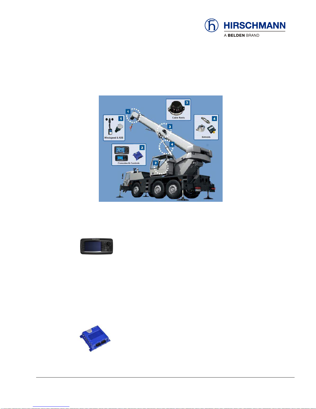
2.1.3 Description of the System Components
The qSCALE i2 system is comprised of various components. The typical relative locations of these
components are shown in the photo below.
2.1.3.1 Console (qSCALE i2)
The graphic display console houses the CPU and also displays pertinent information
regarding the RCL configuration. Refer to the Operator’s Manual for detailed operation of the console.
cSCALE Ix consoles are available in 4.3” (I2) and 7” (I3) sizes. The graphic display console displays
pertinent information regarding the RCL configuration. Refer to the Operator’s Manual for detailed operation of the console.
2.1.3.2 cSCALE DIO
The DIO module is an I/O module for the decentralized detection of analog and digital
sensor signals as well as for driving actuators and proportional valves. The DIO module is able to communicate with programmable logic controllers using the CANOpen
protocol.
Page 12

Description of the System
© 2016 Hirschmann Automation and Control GmbH · Mobile Machine Control Solutions · www.beldensolutions.com 12/161
qSCALE i2 Cranes (Tool Version 3.0.34) Service Manual / Issue B / 11-2017 / ac.
2.1.3.3 Pressure Transducers
The pressure transducers convert hydraulic pressure into an electric signal. The
pressure transducers are connected to the CAN bus junction box. One pressure
transducer is connected to the piston side of the lift cylinder and the other to the rod
side.
2.1.3.4 Cable Reel (Length-Angle Sensor)
The length-angle sensor (LWG), often referred to as the “cable reel”, is installed on
the base section of the boom can measure the length and the angle of the boom
along with transmitting signals to the boom tip.
A reeling drum drives either a potentiometer or rotary encoder to measure the length
of the boom. The length cable on the drum connects to the boom tip and can transmit signals from the
chassis through a slip ring within the LWG housing through the length cable to the boom tip.
The angle sensor is either a liquid capacitive angle sensor (WGC) or a MEMS based angle sensor
(WGX). Both length and angle sensor are connected to a CAN bus board which is connected to the bus
system.
2.1.3.5 Anti-Two-Block (A2B) Switch
The anti-two-block switch monitors the load block and its relationship with the head of
the boom. In working condition, the switch is closed. When the load block strikes the
weight, the circuit opens, disengaging a relay output. To check the cable for damage
(short circuit to ground) there is a 4.7k resistor between ground and the contact of the
switch to give a signal back to the central unit. The weight at the anti-two-block
switch keeps the switch closed until the load block strikes it.
Page 13

Description of the System
© 2016 Hirschmann Automation and Control GmbH · Mobile Machine Control Solutions · www.beldensolutions.com 13/161
qSCALE i2 Cranes (Tool Version 3.0.34) Service Manual / Issue B / 11-2017 / ac.
2.1.3.6 Slew (Angle of Rotation) Sensor
This component is an absolute rotary encoder. This slew angle is the angle (rotational
positioning) of the crane boom relative to the truck.
2.1.3.7 Tilt Sensor
This component is a MEMS based inclination sensors, applicable for all kinds of angle and
position measurements on mobile machines. Typical applications include determination of
a crane boom angle, the leveling of an undercarriage, and alignment tasks on mobile
machines.
Page 14
Troubleshooting
© 2016 Hirschmann Automation and Control GmbH · Mobile Machine Control Solutions · www.beldensolutions.com 14/161
qSCALE i2 Cranes (Tool Version 3.0.34) Service Manual / Issue B / 11-2017 / ac.
3 Troubleshooting
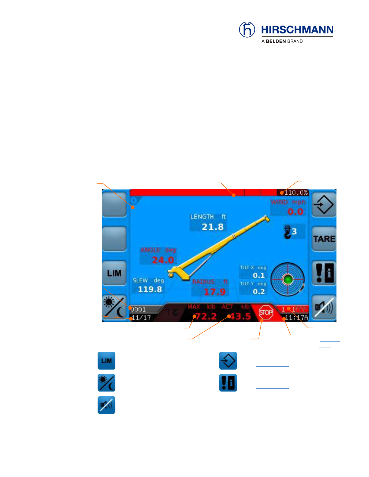
3.1 Troubleshooting with Display
The main working screen displays error codes and symbols in the status bar. The error code cause and
recommended solution can be found using the displayed code in Section 3.1.3. The status of all inputs
and outputs of the system can be checked using several screen displays on the RCL console.
When there are communication errors with safety critical sensors the system will default to maximum
system utilization. Sensors in error state will have their values turn red.
.
User Limits
(see Operators Manual)
Operation Confirm Screen
(see Section 3.1.1)
Display Day/Night Switch
(see Operators Manual)
System Event Information
(see Section 3.1.3)
Silence Alarm
(see Operators Manual)
Function
Keys
Load Capacity
(bar chart)
% Utilization
Operation
Mode
Event code,
as required
(Section
3.1.3)
Lifting Capacity
Date
Time
Warning Symbols
as required
Actual Load
Heartbeat
Page 15

Troubleshooting
© 2016 Hirschmann Automation and Control GmbH · Mobile Machine Control Solutions · www.beldensolutions.com 15/161
qSCALE i2 Cranes (Tool Version 3.0.34) Service Manual / Issue B / 11-2017 / ac.
3.1.1 Op-Mode Confirm Screen
The Op-Mode Confirm screen is the starting point to access diagnostic screens
MAIN
WORKING
SCREEN
OP-MODE
CONFIRM
Setup
(see Operator’s Manual)
Operation Mode Selection
(see Operator’s Manual)
Information Selection
(see Section 3.1.2)
Select Reeving
(see Operator’s Manual)
Graphic Tilt Screen
(see Operator’s Manual)
System Event Information
(see Section 3.1.3)
Function Keys
Page 16
Troubleshooting
© 2016 Hirschmann Automation and Control GmbH · Mobile Machine Control Solutions · www.beldensolutions.com 16/161
qSCALE i2 Cranes (Tool Version 3.0.34) Service Manual / Issue B / 11-2017 / ac.
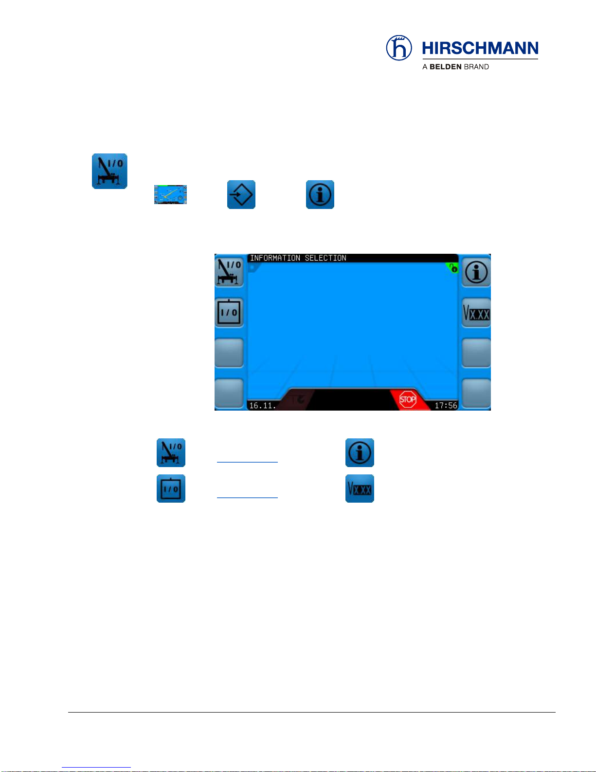
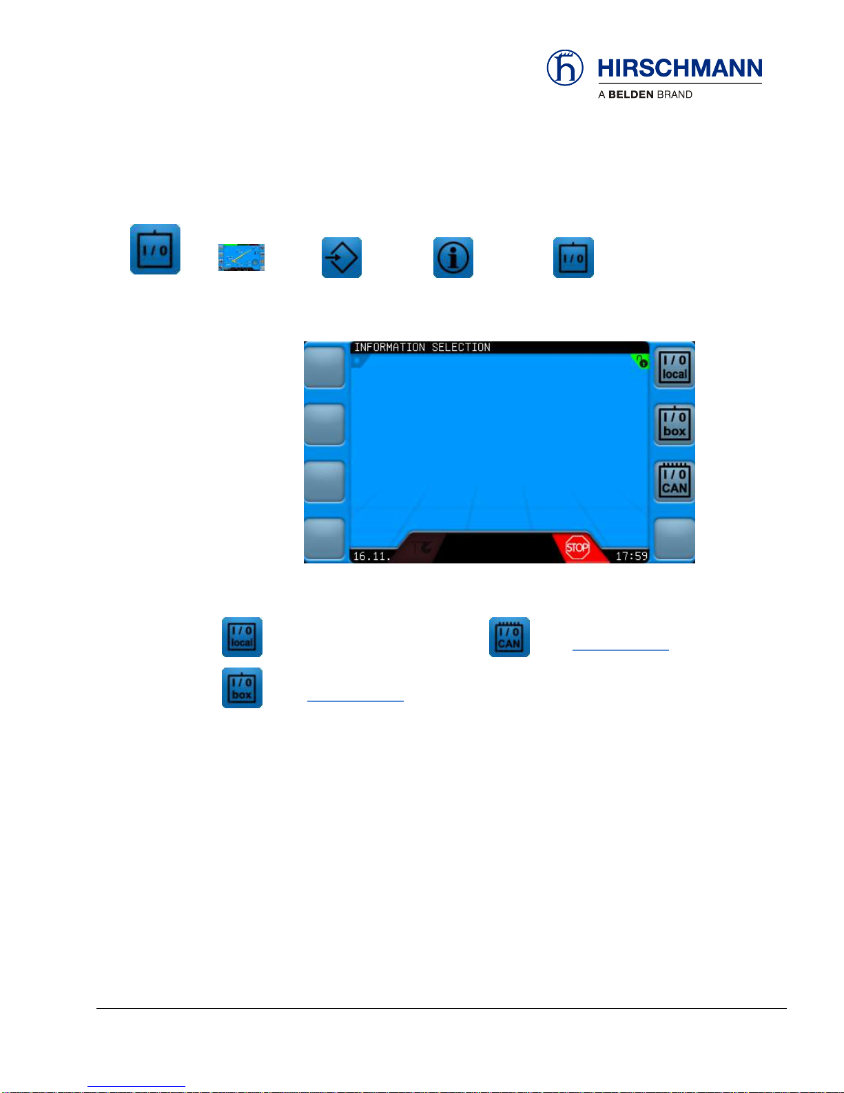
3.1.2 Information Selection Menu
The Information Selection Menu allows the user to view crane, sensor, and software version information
and is the starting point for diagnostic information.
MAIN
WORKING
SCREEN
OP-MODE
CONFIRM
INFORMATION
SELECTION
Sensor Information Screen
(see Section 3.1.2.1)
Crane Information
(see Operators Manual)
Information Selection (extended)
(see Section 3.1.2.2)
Version-Info
(see Operators Manual)
Function Keys
Page 17
Troubleshooting
© 2016 Hirschmann Automation and Control GmbH · Mobile Machine Control Solutions · www.beldensolutions.com 17/161
qSCALE i2 Cranes (Tool Version 3.0.34) Service Manual / Issue B / 11-2017 / ac.
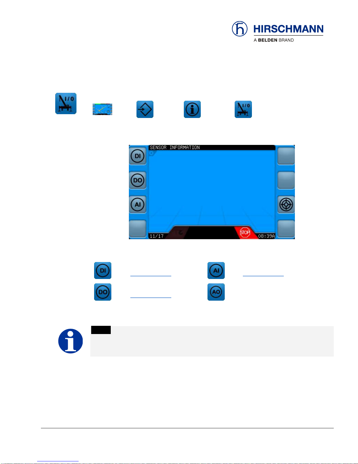
3.1.2.1 Sensor Information Menu
In this menu different information can be displayed about the defined input sensors on the crane.
MAIN
WORKING
SCREEN
OP-MODE
CONFIRM
INFORMATION
SELECTION
SENSOR
INFORMATION
Digital Input Information
(see Section 3.1.2.1.1)
Analog Input Information
(see Section 3.1.2.1.3)
Digital Output Information
(see Section 3.1.2.1.2)
Not available for this project
NOTE
Available screens will vary depending upon system configuration!
Function Keys
Page 18
Troubleshooting
© 2016 Hirschmann Automation and Control GmbH · Mobile Machine Control Solutions · www.beldensolutions.com 18/161
qSCALE i2 Cranes (Tool Version 3.0.34) Service Manual / Issue B / 11-2017 / ac.
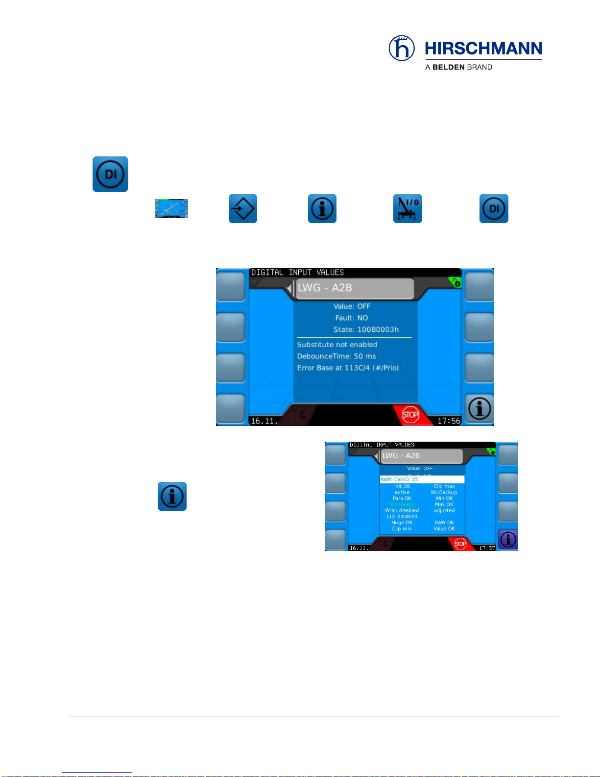
3.1.2.1.1 Digital Input Screen
The Digital Input Screen shows all of the configured digital inputs for the system, including the A2B
signal. These inputs are wired to the DIO Box; refer to your crane system wiring diagram for details.
Use the rotary knob to scroll between all available inputs.
MAIN
WORKING
SCREEN
OP-MODE
CONFIRM
INFORMATION
SELECTION
SENSOR
INFORMATION
DIGITAL
INPUTS
Additional Information
The following information can be found on this screen:
Value Current Value of the Input (False = Low, True = High)
Fault Indication whether an error has occurred
State Current Status of value
Substitute According to Project File Configuration
Debounce Time According to Project File Configuration
Error Base Base error priority of the error when error occurs
Raw Source Available in Additional Information
Function Keys
Page 19

Troubleshooting
© 2016 Hirschmann Automation and Control GmbH · Mobile Machine Control Solutions · www.beldensolutions.com 19/161
qSCALE i2 Cranes (Tool Version 3.0.34) Service Manual / Issue B / 11-2017 / ac.
3.1.2.1.2 Digital Output Screen
Digital Output Screen shows all of the configured digital outputs for the system (if there are no digital
outputs then this screen will not exist). These outputs are wired from the DIO Box; refer to your crane
system wiring diagram for details. Use the rotary knob to scroll between all available outputs.
MAIN
WORKING
SCREEN
OP-MODE
CONFIRM
INFORMATION
SELECTION
SENSOR
INFORMATION
DIGITAL
OUTPUTS
Additional Information
The following information can be found on this screen:
Value False = Low, True = High
Fault Indication whether an error has occurred calculating this value
State Current Status of value
Substitute Not Configurable
Debounce Time According to Project File I/O configuration
Error Base Base error class and priority of the sensor when an error occurs
Raw Source Available in Additional Information
Function Keys
Page 20
Troubleshooting
© 2016 Hirschmann Automation and Control GmbH · Mobile Machine Control Solutions · www.beldensolutions.com 20/161
qSCALE i2 Cranes (Tool Version 3.0.34) Service Manual / Issue B / 11-2017 / ac.
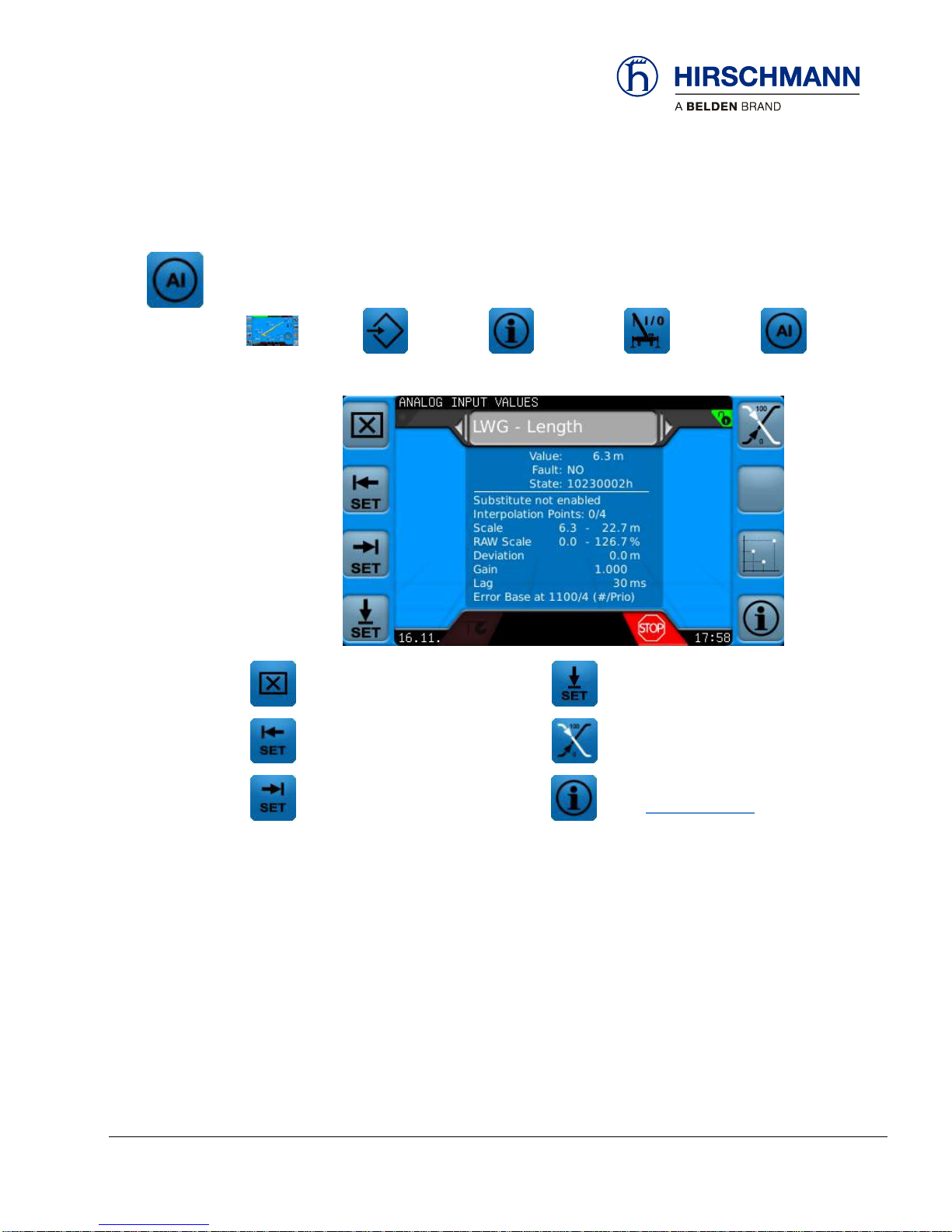
3.1.2.1.3 Analog Input Screen
Analog Input Screen shows all of the configured analog inputs for the system, including CAN sensors.
These outputs are wired from the DIO Box; refer to your crane system wiring diagram for details. Use
the rotary knob to scroll between all available outputs.
MAIN
WORKING
SCREEN
OP-MODE
CONFIRM
INFORMATION
SELECTION
SENSOR
INFORMATION
ANALOG
INPUTS
Delete Sensor Calibration
Set Zero Point Offset
Set Current Sensor Raw Value as
Raw-Value Scale Start
Inverts Raw Value
(100% minus raw value)
Set Current Sensor Raw Value as
Raw-Value Scale End
Additional Information
(see Section 3.1.2.1.4)
The following information can be found on this screen:
Value Current Value
Fault Indication whether an error has occurred calculating this value
State Current Status of value
Substitution According to Project File Configuration
Scale Scaled values are defined in the configurator
Raw Value Scaling: The start of a raw value scaling is assigned to the scale start value and
changes after sensor calibration
Deviation Offset changes after sensor calibration
Gain Filter amplification factor
Lag Filter delay
Error Base Base error class and priority of the sensor when an error occurs
Function Keys
Page 21
Troubleshooting
© 2016 Hirschmann Automation and Control GmbH · Mobile Machine Control Solutions · www.beldensolutions.com 21/161
qSCALE i2 Cranes (Tool Version 3.0.34) Service Manual / Issue B / 11-2017 / ac.
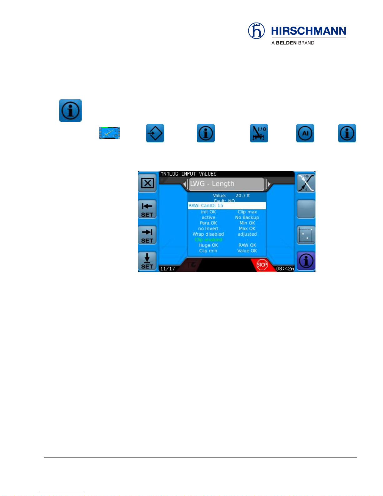
3.1.2.1.4 Extended Analog Input Information
Analog Input Screen shows all of the configured analog inputs for the system, including CAN sensors.
These outputs are wired from the DIO Box; refer to your crane system wiring diagram for details. Use
the rotary knob to scroll between all available outputs.
MAIN
WORKING
SCREEN
OP-MODE
CONFIRM
INFORMATION
SELECTION
SENSOR
INFORMATION
ANALOG
INPUTS
EXT
ANALOG
INPUT
The following information can be found on this screen:
Raw Source Value
The display of clip, wrap, and inverted as defined in Project File Configuration
Deviations from the default value are highlighted in color.
Page 22
Troubleshooting
© 2016 Hirschmann Automation and Control GmbH · Mobile Machine Control Solutions · www.beldensolutions.com 22/161
qSCALE i2 Cranes (Tool Version 3.0.34) Service Manual / Issue B / 11-2017 / ac.
3.1.2.2 Extended Information Menu
In this menu different information can be displayed about the defined sensors.
MAIN
WORKING
SCREEN
OP-MODE
CONFIRM
INFORMATION
SELECTION
EXTENDED
INFORMATION
Console I/O
Not used for this Project
CAN Sensor Information
(see Section 3.1.2.2.1)
DIO I/O
(see Section 3.1.2.2.1)
Function Keys
Page 23
Troubleshooting
© 2016 Hirschmann Automation and Control GmbH · Mobile Machine Control Solutions · www.beldensolutions.com 23/161
qSCALE i2 Cranes (Tool Version 3.0.34) Service Manual / Issue B / 11-2017 / ac.
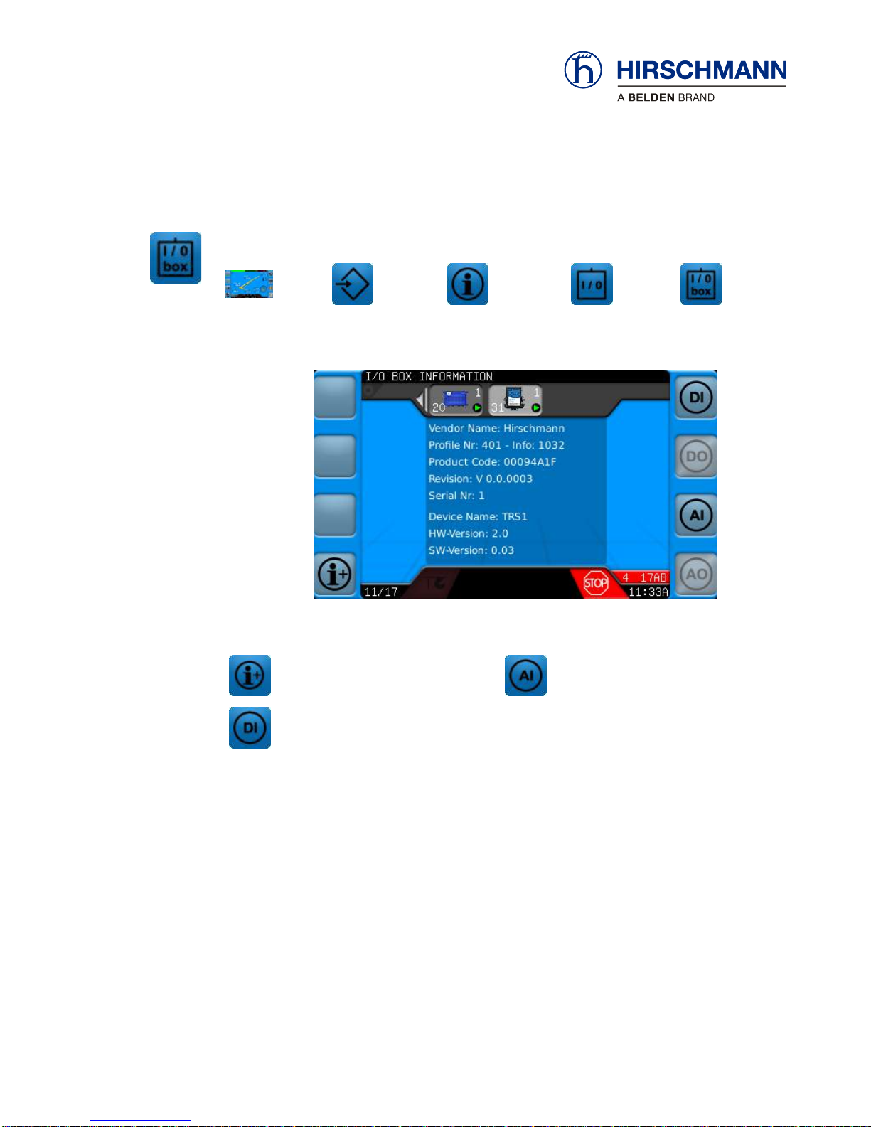
3.1.2.2.1 DIO I/O Information
I/O information for DIO Module (standard) and optional TRS10-W2 (wireless sensor receiver) are found
on this screen.
MAIN
WORKING
SCREEN
OP-MODE
CONFIRM
INFORMATION
SELECTION
EXTENDED
INFORMATION
DIO
INFO
Console I/O
Not used for this Project
Analog Input Information
(Wireless Sensor Values)
Digital Input Information
(Wireless Sensor Values)
Function Keys
Page 24
Troubleshooting
© 2016 Hirschmann Automation and Control GmbH · Mobile Machine Control Solutions · www.beldensolutions.com 24/161
qSCALE i2 Cranes (Tool Version 3.0.34) Service Manual / Issue B / 11-2017 / ac.
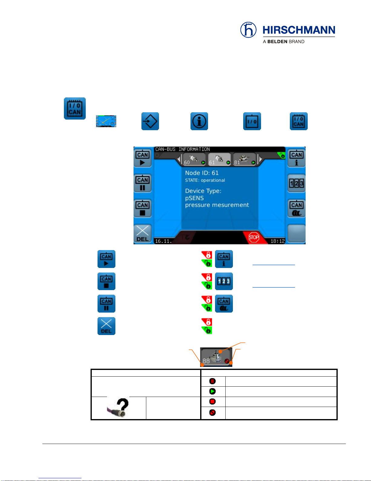
3.1.2.2.2 CAN Sensor Information
This menu shows the status of the CAN sensors. This is the place to start if a problem with a sensor is
suspected.
MAIN
WORKING
SCREEN
OP-MODE
CONFIRM
INFORMATION
SELECTION
EXTENDED
INFORMATION
CAN
INFO
Initializes Selected Sensor
Additional CAN Information
(See Section 3.1.2.2.3)
Stops Selected Sensor
PDO Raw Data Information
(See Section 3.1.2.2.4)
Sets Status to “PreOperational”
CAN Bus is Restarted
(List is Updated)
Sets the Node ID to 127
Icon
Status
Icon Shows Type of Sensor
Sensor Pre-Operational
Sensor Operational
Appears When
Node ID Differs
from Configuration
Sensor Stopped
Sensor Not Connected
Function Keys
Symbols
Status
Icon
Node
ID
Page 25

Troubleshooting
© 2016 Hirschmann Automation and Control GmbH · Mobile Machine Control Solutions · www.beldensolutions.com 25/161
qSCALE i2 Cranes (Tool Version 3.0.34) Service Manual / Issue B / 11-2017 / ac.
3.1.2.2.3 Extended CAN Information
To view additional information about a specific CAN sensor press the Extended CAN Information Function Button.
MAIN
WORKING
SCREEN
OP-MODE
CONFIRM
INFORMATIO
N SELECTION
EXTENDED
INFORMATION
CAN
INFO
EXT
CAN
INFO
Page 26
Troubleshooting
© 2016 Hirschmann Automation and Control GmbH · Mobile Machine Control Solutions · www.beldensolutions.com 26/161
qSCALE i2 Cranes (Tool Version 3.0.34) Service Manual / Issue B / 11-2017 / ac.
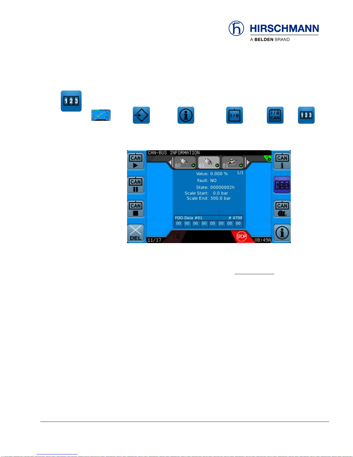
3.1.2.2.4 PDO Raw Data Transmission
To view additional information about a specific CAN sensor press the Extended CAN Information Function Button.
MAIN
WORKING
SCREEN
OP-MODE
CONFIRM
INFORMATIO
N SELECTION
EXTENDED
INFORMATION
CAN
INFO
PDO
The following information can be found on this screen:
Value Current Value of the Input (% =
𝑟𝑎𝑤𝑉𝑎𝑙𝑢𝑒−𝑠𝑐𝑎𝑙𝑒𝑆𝑡𝑎𝑟𝑡
𝑠𝑐𝑎𝑙𝑒𝐸𝑛𝑑−𝑠𝑐𝑎𝑙𝑒𝑆𝑡𝑎𝑟𝑡
)
Fault Indication whether an error has occurred
State Current Status of value
Scale Start
Scale End
PDO Data Raw CAN Value Read from the Sensor
Page 27
Troubleshooting
© 2016 Hirschmann Automation and Control GmbH · Mobile Machine Control Solutions · www.beldensolutions.com 27/161
qSCALE i2 Cranes (Tool Version 3.0.34) Service Manual / Issue B / 11-2017 / ac.
3.1.3 Error Codes
The qSCALE i2 system uses various error codes to report and log various activity. See the section in
the appendix, Error Code Tables, for a complete list of codes, their cause, and possible solution.
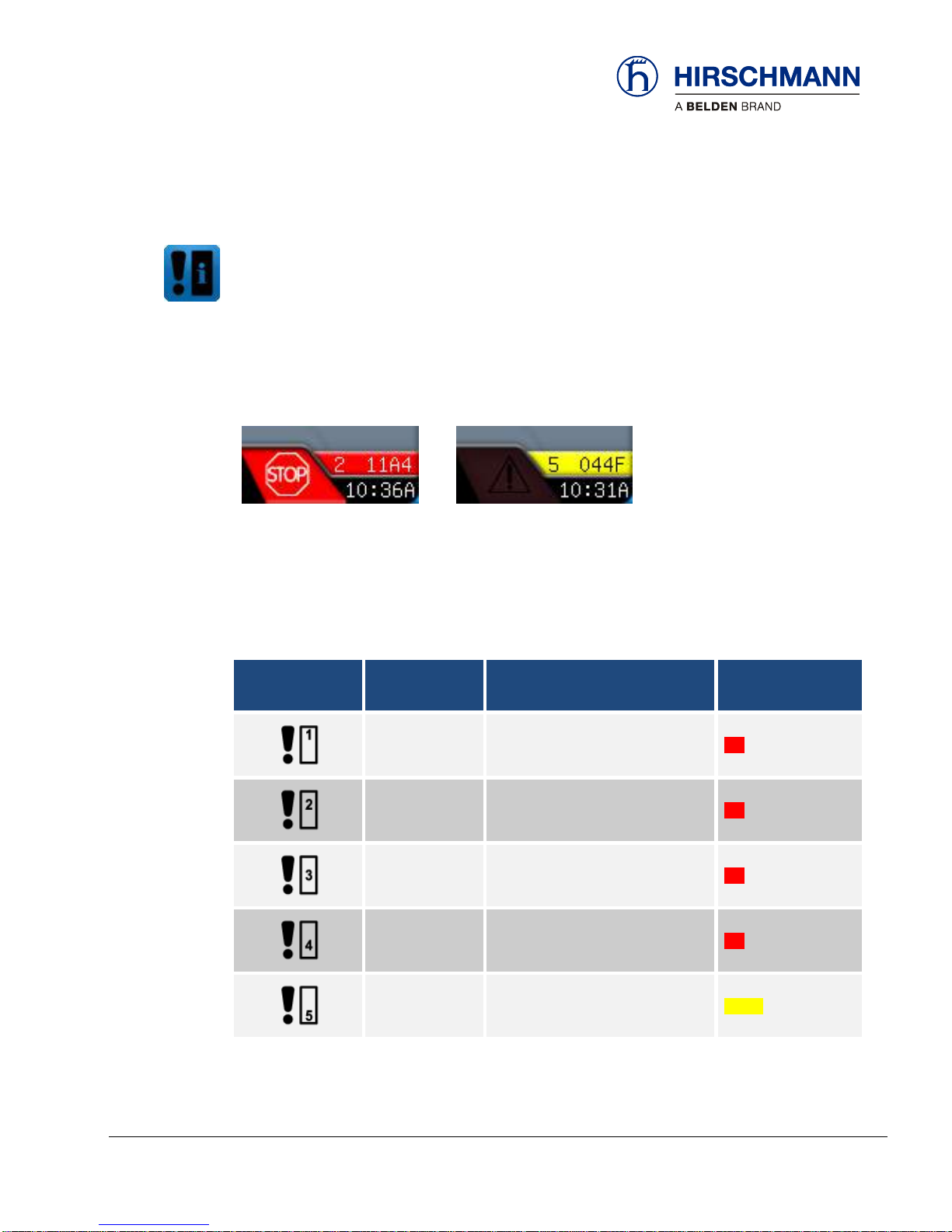
3.1.3.1 Indication of an Event Message
If necessary, a code ‘# ####’ is displayed at the marked location on the display. If several event messages are simultaneously present, only the most important will be displayed here.
3.1.3.2 Event Classes
The leading digit of an event code indicates the event class.
Depending on the importance of the message they are divided into different classes:
Symbol
in event menu
Event class
Definition
Color
1 ####
Emergency errors
red
2 ####
Alerts
red
3 ####
Critical errors
red
4 ####
Errors
red
5 ####
Warnings
yellow
System event
message code
(examples)
Page 28
Troubleshooting
© 2016 Hirschmann Automation and Control GmbH · Mobile Machine Control Solutions · www.beldensolutions.com 28/161
qSCALE i2 Cranes (Tool Version 3.0.34) Service Manual / Issue B / 11-2017 / ac.
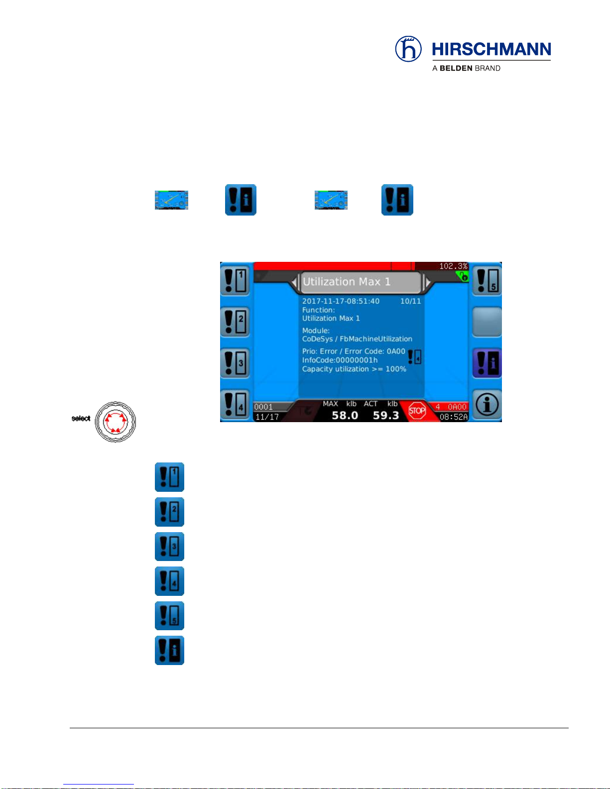
3.1.3.3 System Event Information
When there is an error event, the Error Event Button will activate. Pressing the Error Event button will
call up the System Event Information Screen.
OR
MAIN
WORKING
SCREEN
ERROR
EVENT
OP-MODE
CONFIRM
ERROR
EVENT
If several messages of the same class are present use the dial control to change the current message.
The function key is dark blue when that screen is activated.
View Errors of Class 1
View Errors of Class 2
View Errors of Class 3
View Errors of Class 4
View Errors of Class 5
View Errors of All Classes
Page 29

Troubleshooting
© 2016 Hirschmann Automation and Control GmbH · Mobile Machine Control Solutions · www.beldensolutions.com 29/161
qSCALE i2 Cranes (Tool Version 3.0.34) Service Manual / Issue B / 11-2017 / ac.
3.2 Hardware Troubleshooting
3.2.1 What is Wrong?
I HAVE AN ERROR CODE INDICATED ON THE CONSOLE
Please go to Section 3.1.3
THE DISPLAYED ANGLE DOES NOT MATCH THE ACTUAL BOOM ANGLE
Start in Section3.2.5 to troubleshoot possible problems with the boom angle measurement.
THE DISPLAYED LENGTH DOES NOT MATCH THE ACTUAL BOOM LENGTH
Start in Section 3.2.6 to troubleshoot possible problems with the boom length measurement.
THE DISPLAYED PRESSURES DOES NOT MATCH THE ACTUAL PRESSURES
Start in Section 3.2.7 to troubleshoot possible problems with the pressure transducers.
THE DISPLAYED LOAD DOES NOT MATCH THE ACTUAL LOAD
Please note that if the system is equipped with pressure transducers, the indicated load is calculated by
the system from the geometry information in the computer, the operator’s selections, and all the sensor
inputs. If the load display is incorrect, it may be due to an error in one or more of these inputs! Refer to
Section 3.2.8 to narrow down the source of your problem.
THE CONSOLE DISPLAY IS BLANK
If the console does not show any sign at all (no lights, no buzzer, and no display), the problem is in the
wiring between console and central unit, or the console itself has a problem. Refer to Section 3.2.10 for
further troubleshooting.
I HAVE AN A2B PROBLEM
Please go to Section 3.2.8.1.1
I HAVE A CAN BUS PROBLEM
Please go to Section 3.2.13
Questions:
Page 30

Troubleshooting
© 2016 Hirschmann Automation and Control GmbH · Mobile Machine Control Solutions · www.beldensolutions.com 30/161
qSCALE i2 Cranes (Tool Version 3.0.34) Service Manual / Issue B / 11-2017 / ac.
THE DISPLAYED SLEWING DOES NOT MATCH THE ACTUAL SLEWING ANGLE
Refer to Section 3.2.10 to troubleshoot possible problems with the slew angle measurement.
THE DISPLAYED TILT DOES NOT MATCH THE ACTUAL TILT
Start in Section 3.2.11 to troubleshoot possible problems with the tilt measurement
THE CONSOLE DISPLAY IS BLANK
If the console does not show any sign at all (no lights, no buzzer, and no display), the problem is in the
wiring between console and central unit, or the console itself has a problem. Refer to Section 3.2.12 for
further troubleshooting.
Page 31

Troubleshooting
© 2016 Hirschmann Automation and Control GmbH · Mobile Machine Control Solutions · www.beldensolutions.com 31/161
qSCALE i2 Cranes (Tool Version 3.0.34) Service Manual / Issue B / 11-2017 / ac.
3.2.2 Initial System Inspection
Page 32

Troubleshooting
© 2016 Hirschmann Automation and Control GmbH · Mobile Machine Control Solutions · www.beldensolutions.com 32/161
qSCALE i2 Cranes (Tool Version 3.0.34) Service Manual / Issue B / 11-2017 / ac.
Page 33

Troubleshooting
© 2016 Hirschmann Automation and Control GmbH · Mobile Machine Control Solutions · www.beldensolutions.com 33/161
qSCALE i2 Cranes (Tool Version 3.0.34) Service Manual / Issue B / 11-2017 / ac.
3.2.3 Simple Corrective Actions
NOTE
Not all codes produced by the iSCALE system are “ERRORS”. Some codes generated are simply for the event log. Others indicate load chart, limits exceeded, and safety warnings. See Sec-
tion 6.2 for more detail on errors.
Error Codes are displayed in order of priority – most critical codes first. Therefore, multiple
codes are possible depending upon the situation.
Page 34

Troubleshooting
© 2016 Hirschmann Automation and Control GmbH · Mobile Machine Control Solutions · www.beldensolutions.com 34/161
qSCALE i2 Cranes (Tool Version 3.0.34) Service Manual / Issue B / 11-2017 / ac.
3.2.4 Indicator Definitions
Indicators are located on the Central Control Unit and the Console to assist with troubleshooting basic
power and software issues.
3.2.4.1 Indicators on the cSCALE DIO Module
Visual LED Indicators are located on the top of the DIO Module
PON
Power ON
POK
Power OK
SR
Safety Relay Active
3.2.4.2 Indicator on Console Unit
Operating display: Illuminates green when the supply voltage is connected.
Operating
Display Light
Page 35

Troubleshooting
© 2016 Hirschmann Automation and Control GmbH · Mobile Machine Control Solutions · www.beldensolutions.com 35/161
qSCALE i2 Cranes (Tool Version 3.0.34) Service Manual / Issue B / 11-2017 / ac.
3.2.5 Boom Angle Sensing
The system measures the angle of the main boom of the machine with an angle sensor. The angle
sensor is either contained within the cable reel or mounted directly to the main boom.
3.2.5.1 Boom Angle Sensing Overview
The WGC angle sensor is based on liquid capacitive inclinometer technology. As the angle changes so
will the fluid, and with it the capacitance changes.
The WGX angle sensor is based on Micro-Electro-Mechanical Systems (MEMS) inclinometer. The
angle is measured with relative change in electrical capacitance in the MEMS cell.
Start by verifying the actual angle to display the angle at several positions. The CAN Bus is digital and
as such will either transmit the signal correctly or not at all. The raw value of the sensor can be monitored and should be checked against a digital level outside of the system mounted on the boom. If the
raw value varies from the actual value, replace the angle sensor. Refer to sensor documentation for
expected accuracy values.
The voltage supplied to either sensor should ideally be between 11.0 and 26.0V. If the angle sensor is
mounted directly to the boom, the CAN Bus cable will supply the sensor with power. If the angle sensor
is located within a cable reel, it can be connected to either a LWG board or a CAN Junction Board. This
board will supply the sensor with power.
The signal runs from the angle sensor to the CAN junction block. From there, it travels as digital information on the CAN Bus to the central processing unit.
Unplug the CAN cable from the angle sensor and measure the voltage between pins 3 (GND) and 2 (+).
If the voltage is outside of the acceptable range, power to the CAN line may be the issue. Check the
entire CAN Bus system to ensure proper wiring and connections.
WGC Sensor
WGX Sensor
Basic
Troubleshooting
Block Diagram
Angle Sensor Mounted
on Boom
Page 36
Troubleshooting
© 2016 Hirschmann Automation and Control GmbH · Mobile Machine Control Solutions · www.beldensolutions.com 36/161
qSCALE i2 Cranes (Tool Version 3.0.34) Service Manual / Issue B / 11-2017 / ac.
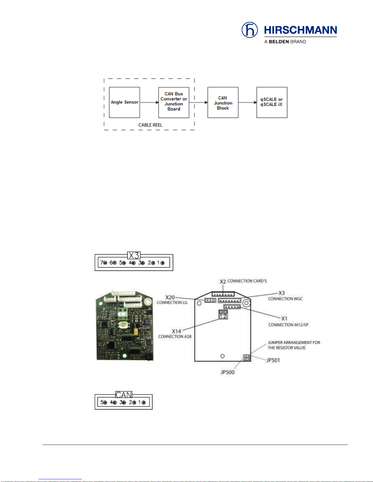
The signal runs from the angle sensor to the CAN Bus converter board or CAN Bus junction block
board, both located in the cable reel. From there, it travels as digital information on the CAN Bus to the
central processing unit.
Measure the voltage between pins 3 (GND) and 2 (+) while the angle sensor is still connected to the
CAN Bus Converter or Junction Board. If the voltage is not within the acceptable range, unplug the
sensor and re-measure. If unplugging the sensor resolved the voltage issue, replace the sensor. If the
voltage is still outside of the acceptable range, unplug the power source to the CAN Bus Converter or
Junction Board and re-measure. If unplugging the board resolved the voltage issue, replace the board.
If the voltage is still outside of the acceptable range, power to the CAN line may be the issue. Check the
entire CAN Bus system to ensure proper wiring and connections.
The CAN Bus Converter Board acts as a junction for the angle sensor, and converts the length and A2B
signals to CAN. The angle sensor will be connected to X3.
The CAN Bus Junction Board is a passive device that acts as a junction for CAN sensors.
Block Diagram
Angle Sensor inside
Cable Reel
CAN Bus Converter
Board
CAN Bus Junction
Board
Page 37

Troubleshooting
© 2016 Hirschmann Automation and Control GmbH · Mobile Machine Control Solutions · www.beldensolutions.com 37/161
qSCALE i2 Cranes (Tool Version 3.0.34) Service Manual / Issue B / 11-2017 / ac.
3.2.5.2 Boom Angle Sensing Error – Flow Chart
Use the following flow chart to troubleshoot errors with boom angle sensing for both WGX and WGC
angle sensors.
Flow Chart
Page 38

Troubleshooting
© 2016 Hirschmann Automation and Control GmbH · Mobile Machine Control Solutions · www.beldensolutions.com 38/161
qSCALE i2 Cranes (Tool Version 3.0.34) Service Manual / Issue B / 11-2017 / ac.
3.2.6 Boom Length Sensing
The system measures the length of the main boom of the machine with a length sensor. The length
sensor is contained within the cable reel.
3.2.6.1 Boom Length Sensing Overview
Start by verifying the actual length to the display. Boom length is the distance from the heel pin to the
center of the front sheave wheel. The boom length is displayed on the working screen of the console.
The CAN Bus is digital and as such will either transmit the signal correctly or not at all. If the length
measurement does not match the displayed length, start troubleshooting by checking the length cable
tension. If tension is lacking, check the cable reel to ensure it has the proper pretension. This varies
upon the type of cable reel used.
The voltage supplied to either length sensor will be through the CAN Bus Converter Board (length potentiometers) or a CAN Junction Board (rotary encoders).
Basic
Troubleshooting
Block Diagram
Page 39

Troubleshooting
© 2016 Hirschmann Automation and Control GmbH · Mobile Machine Control Solutions · www.beldensolutions.com 39/161
qSCALE i2 Cranes (Tool Version 3.0.34) Service Manual / Issue B / 11-2017 / ac.
3.2.6.2 Rotary Encoder Troubleshooting
The rotary encoder is driven by a belt drive from the drum shaft, and thus does not contain a gear set
within the cable reel housing. The sensor outputs a CAN signal directly and plugs into a CAN Bus Junction Board. The ideal voltage supplied to the rotary encoder should be between 11.0 and 26.0V.
Measure the voltage between pins 3 (GND) and 2 (+) while the rotary encoder is still connected to the
CAN Bus Junction Board. If the voltage is not within the acceptable range, unplug the sensor and remeasure. If unplugging the sensor resolved the voltage issue, replace the sensor. If the voltage is still
outside of the acceptable range, unplug the power source to the CAN Bus Junction Board and remeasure. If unplugging the board resolved the voltage issue, replace the board. If the voltage is still
outside of the acceptable range, power to the CAN line may be the issue. Check the entire CAN Bus
system to ensure proper wiring and connections.
The CAN Bus Junction Board is a passive device that acts as a junction for CAN sensors.
Page 40

Troubleshooting
© 2016 Hirschmann Automation and Control GmbH · Mobile Machine Control Solutions · www.beldensolutions.com 40/161
qSCALE i2 Cranes (Tool Version 3.0.34) Service Manual / Issue B / 11-2017 / ac.
3.2.6.3 Length Potentiometer Troubleshooting
The length sensor is a potentiometer that is driven by a gear drive from the cable drum. As the length
changes, the cable drum will turn and with it, the potentiometer’s axle.
The CAN Bus Converter Board the length and A2B signals to CAN, and acts as a junction to the angle
sensor. The length sensor will be connected to X20.
Fully retract the boom and turn the shaft of the length potentiometer opposite of the cable payoff with a
small screwdriver until it comes to a soft stop. That should bring the sensor voltage to 0V (+/- 0.1Volt)
between Pin 3 (-) and Pin 2 of connector X20.
NOTE
After this step is done, the length sensor needs to be calibrated.
Go back to your indication screen and compare length indicated and actual length again. If zeroing the
length potentiometer and recalibrating did not resolve the issue (indicated length varies more than 0.3
feet from actual length), continue.
Page 41

Troubleshooting
© 2016 Hirschmann Automation and Control GmbH · Mobile Machine Control Solutions · www.beldensolutions.com 41/161
qSCALE i2 Cranes (Tool Version 3.0.34) Service Manual / Issue B / 11-2017 / ac.
Verify that the sensor is being supplied with about 1.6V by measuring between Pin 3 (-) and Pin 1 (+) of
terminal X20. If the voltage is outside of a range of 1.4V to 1.8V, the converter board may be defective.
Unplug the length sensor and measure again. If the voltage is still out of the correct range, exchange
the converter board. If unplugging the length sensor made the voltage return into the acceptable range,
exchange the length sensor. If the voltage is correct, continue.
The length sensor returns a voltage between 0V at 0 turns of the length pot (= fully retracted) and 1.64V
at 10 turns. How many turns you get at full extension depends on the gear ratio, the boom length, the
length cable used, and the spooling pattern. The following table shows the expected output voltage
(measured between X20-3 and X20-2 Signal) for each complete turn of the length potentiometer. Note
that this does not synchronize to the number of turns of the cable reel.
Length Sensor Signal on Pin 3
Turns
Voltage X20-3 to
X20-2
0
0.00 1 0.16 2 0.33 3 0.49 4 0.66 5 0.82 6 0.98 7 1.15 8 1.31 9 1.47
10
1.64
Table 4 - 1
Note: Actual voltages will vary slightly.
Go back to your indication screen and compare length indicated and actual again. If the indicated length
varies significantly from your actual length (more than 0.3 feet), the length sensor is defective and
should be exchanged.
Page 42

Troubleshooting
© 2016 Hirschmann Automation and Control GmbH · Mobile Machine Control Solutions · www.beldensolutions.com 42/161
qSCALE i2 Cranes (Tool Version 3.0.34) Service Manual / Issue B / 11-2017 / ac.
3.2.6.4 Cable Reel Length Cable Replacement Procedure
Replace the length cable using the following procedure:
1. Cut old cable at cable drum.
2. Disconnect damaged length cable from junction box at the boom nose.
3. Remove cable reel from mounting brackets.
4. Remove damaged length cable, which is connected to the slip rings in the cable reel, from slip
ring terminal.
5. On the backside of the cable reel, open the strain relief attached to the axle in the center of the
drum. Pull existing length cable out of the cable reel.
6. Pull new length cable through the strain relief and push it through the axle of the reeling drum.
Tighten new strain relief to ensure sealing.
7. Reconnect the length cable to the slip ring.
8. Loosely spool cable onto reel prior to mounting by reeling drum counter-clockwise.
9. Remount cable reel to the boom.
10. Unwind cable and re-spool neatly using cable reel spring tension to keep the cable taught.
NOTE: A well-wrapped first layer aids in cable spooling during operation!
11. Set pre-load on cable reel by turning the drum in the direction of spring tension
a. 154 Reel: 3 to 5 turns
b. 509 Reel: 3 to 5 turns
c. 521 Reel: 5 to 8 turns
12. Run the new length cable through the cable guides and wrap the length cable around the
boom tip anchoring and secure. If applicable, leave enough length cable to connect into the
boom tip junction box.
13. If the system has a rotary encoder, skip to Step 15.
14. Reset the length potentiometer. The screw is located in center of white gear. With the boom
fully retracted, turn the potentiometer counterclockwise carefully until it stops. Finally turn the
potentiometer clockwise ¼ turn. Recheck the length display.
15. Follow the recalibrate length sensor.
Procedure for Length
Cable replacement
Page 43

Troubleshooting
© 2016 Hirschmann Automation and Control GmbH · Mobile Machine Control Solutions · www.beldensolutions.com 43/161
qSCALE i2 Cranes (Tool Version 3.0.34) Service Manual / Issue B / 11-2017 / ac.
3.2.6.5 Boom Length Sensor Error – Flow Chart
Use the following flow chart to troubleshoot errors with length sensing.
Flow Chart
Page 44

Troubleshooting
© 2016 Hirschmann Automation and Control GmbH · Mobile Machine Control Solutions · www.beldensolutions.com 44/161
qSCALE i2 Cranes (Tool Version 3.0.34) Service Manual / Issue B / 11-2017 / ac.
3.2.7 Pressure Sensing
The System measures the pressure of the boom lift cylinder for both rod and piston side. Both sensors
communicate on the CAN Bus.
3.2.7.1 Pressure Sensing Overview
The signal runs from the pressure sensor travels as digital information on the CAN Bus to the central
processing unit.
Note that the load displayed on the LMI is not a direct measurement when using pressure transducers;
rather, it is a calculated value. Ensure that the hydraulic system is functioning as intended and that
sensor values, mainly length and angle, are functioning correctly prior to troubleshooting the pressure
transducers.
3.2.7.2 Pressure Sensing Error – Flow Chart
Use the following flow chart to troubleshoot errors with pressure sensing.
Block Diagram
Flow Chart
Page 45

Troubleshooting
© 2016 Hirschmann Automation and Control GmbH · Mobile Machine Control Solutions · www.beldensolutions.com 45/161
qSCALE i2 Cranes (Tool Version 3.0.34) Service Manual / Issue B / 11-2017 / ac.
3.2.8 Load Sensing
Please note that when using pressure transducers the load displayed by the RCL is not a direct measurement, but a calculated value that is based on many factors. Factors included that are outside of the
measured values include:
Operator settings such as:
Operating mode/configuration
Parts of Line/Reeving
Outrigger position
Rigging parts such as:
Hook block weight
Sling weights, etc.
Tip height (length of load line used)
Boom weights
Boom attachments such as:
Stowed jibs
Telescopic jib, etc.
Before checking the system for a load-reading problem, make sure all of the above has been ruled out.
When you still feel the system is reading a sensor wrong and thus displaying an incorrect load, use the
following:
Use the previous sections and the individual sensor signal displayed on the screen to double-check the
following:
boom length reading
angle transducer reading
pressure transducer readings
If all are correct, use the zero setting and calibration screens to calibrate angle, length, slew, and tilt. If
you still have a problem, replace pressure transducer(s).
Page 46

Troubleshooting
© 2016 Hirschmann Automation and Control GmbH · Mobile Machine Control Solutions · www.beldensolutions.com 46/161
qSCALE i2 Cranes (Tool Version 3.0.34) Service Manual / Issue B / 11-2017 / ac.
3.2.8.1.1 Anti-Two Block Switch (A2B)
The system measures the load block and its relationship to the head of the boom. The A2B switch is
located at the nose of the boom.
3.2.9 A2B Switch Overview
The signal runs from the A2B as a CAN Bus input of the central unit.
NOTE
Some systems have two (2) A2B switches wired in series.
Block Diagram
Page 47

Troubleshooting
© 2016 Hirschmann Automation and Control GmbH · Mobile Machine Control Solutions · www.beldensolutions.com 47/161
qSCALE i2 Cranes (Tool Version 3.0.34) Service Manual / Issue B / 11-2017 / ac.
3.2.9.1 A2B Problem – Flow Chart
Use the following flow chart to troubleshoot errors with A2B switch input.
Flow Chart
Page 48

Troubleshooting
© 2016 Hirschmann Automation and Control GmbH · Mobile Machine Control Solutions · www.beldensolutions.com 48/161
qSCALE i2 Cranes (Tool Version 3.0.34) Service Manual / Issue B / 11-2017 / ac.
3.2.10 Slew Sensing Overview
The system measures the slewing (rotational position) of the crane’s boom and turret with a rotary encoder. The slewing sensor is contained within the slip ring assembly.
3.2.10.1 Slew Sensing Overview
The slew encoder is driven by the slip ring axle. The slew angle is displayed on the CAN Sensor
Screen.
3.2.10.2 Slew (Rotation Angle) Sensing Error – Flow Chart
Use the following flow chart to troubleshoot errors with slew sensing.
Block Diagram
Flow Chart
Page 49

Troubleshooting
© 2016 Hirschmann Automation and Control GmbH · Mobile Machine Control Solutions · www.beldensolutions.com 49/161
qSCALE i2 Cranes (Tool Version 3.0.34) Service Manual / Issue B / 11-2017 / ac.
3.2.11 Tilt Sensing
The system measure the tilt (level) of the crane.
3.2.11.1 Tilt XY Sensing Overview
The system measures the tilt (level) of the crane.
The signal runs from the tilt sensors as digital information on the CAN Bus to the central unit. The CAN
Bus is digital and as such will either transmit the signal correctly or not at all.
Start by verifying the actual tilt angle to the display tilt angle at several positions. The raw value of the
sensor can be monitored and should be checked against a digital level outside of the system mounted
on a machined flat surface parallel to the ground. If the raw value varies from the actual value, replace
the tilt sensor. Refer to sensor documentation for expected accuracy values. The voltage supplied to
either sensor should ideally be between 11.0 and 26.0V. The CAN Bus cable will supply the sensor with
power.
Block Diagram
Page 50

Troubleshooting
© 2016 Hirschmann Automation and Control GmbH · Mobile Machine Control Solutions · www.beldensolutions.com 50/161
qSCALE i2 Cranes (Tool Version 3.0.34) Service Manual / Issue B / 11-2017 / ac.
3.2.11.2 Tilt XY Sensing Error – Flow Chart
Use the following flow chart to troubleshoot errors with Tilt Sensing.
Flow Chart
Page 51

Troubleshooting
© 2016 Hirschmann Automation and Control GmbH · Mobile Machine Control Solutions · www.beldensolutions.com 51/161
qSCALE i2 Cranes (Tool Version 3.0.34) Service Manual / Issue B / 11-2017 / ac.
3.2.12 No Console Display
If the console never displays an image, check if power is being supplied to the console. Measure the
voltage between Pin 1 (+) and Pin 3 (GND). If power is being supplied, the console must be replaced. If
power is not being supplied, trace the wiring to determine why.
Page 52

Troubleshooting
© 2016 Hirschmann Automation and Control GmbH · Mobile Machine Control Solutions · www.beldensolutions.com 52/161
qSCALE i2 Cranes (Tool Version 3.0.34) Service Manual / Issue B / 11-2017 / ac.
3.2.13 CAN Bus Communications
CAN Bus - a serial bus protocol to connect individual systems and sensors as an alternative to conven-
tional multi-wire cables. It allows crane components to communicate on a single bus: a dual-wire networked data bus with speed up to 1Mbps.
The use of a CAN Bus design allows for all nodes (sensor, controller and console) signals to be networked over a common pair of cables. The signals generated by all sensors are slave signals sent with
a digital identifier over common cables. The data transmitted is used by the controller (master). The
data can be interpreted, and information and controls sent from the controller to provide crane safety
functions. Each node has a unique identifier. This allows for a common pair of shielded wires (the bus)
to carry all signals.
Page 53

Troubleshooting
© 2016 Hirschmann Automation and Control GmbH · Mobile Machine Control Solutions · www.beldensolutions.com 53/161
qSCALE i2 Cranes (Tool Version 3.0.34) Service Manual / Issue B / 11-2017 / ac.
The CAN Bus requires that 120 Ohm resistors be at each end of the CAN BUS. The resistors in parallel
yield 60 Ohms of resistance between the CAN High and CAN Low cables.
The signals are generated by nodes on the CAN BUS. The nodes generate and consume data over the
CAN Bus. The CAN High and CAN Low signals are equal and opposite of each other in amplitude and
have the same duration (refer to image above for visual).
Adequate voltage supply is required for all nodes on a CAN Bus. A common source of issues is Voltage
drop due to added resistance from a corroded connection. As resistance increases, a corresponding
voltage drop occurs corrupting the signal generated. The CAN signal will begin to lose the top of the
high signal and no longer mirror the reflection (parity) of the CAN low signal.
Page 54

Troubleshooting
© 2016 Hirschmann Automation and Control GmbH · Mobile Machine Control Solutions · www.beldensolutions.com 54/161
qSCALE i2 Cranes (Tool Version 3.0.34) Service Manual / Issue B / 11-2017 / ac.
CAN Power can be verified by testing the CAN connectors per this layout:
Connector M12, 5 contacts
Pin Layout (CiA DR-303-1 7.2)
(Solid for Male Pins)
(Hollow for Female Sockets)
Pin 1 Shield
Pin 2 + Ub
Pin 3 Ground
Pin 4 CAN High
Pin 5 CAN Low
Male Female
(Pins) (Sockets)
Measure between pin 3 and pin 2 to measure the machine voltage. If you see voltage, check all pins for
continuity.
X1 Pin
CAN
1
CAN_SHLD
2
CAN +UB
3
CAN GND
4
CAN_H
5
CAN_L
Table 4-2
Page 55

Commissioning
© 2016 Hirschmann Automation and Control GmbH · Mobile Machine Control Solutions · www.beldensolutions.com 55/161
qSCALE i2 Cranes (Tool Version 3.0.34) Service Manual / Issue B / 11-2017 / ac.
4 Commissioning
4.1 Adding Wireless Sensors
If the system is equipped with wireless sensors the sensor must be added via the I/O Box Information
Screen
MAIN
WORKING
SCREEN
OP-MODE
CONFIRM
INFORMATION
SELECTION
EXTENDED
INFORMATION
DIO
INFO
AI
WIRELESS
INFO
1. Press the CAN SET
button to add
wireless sensor
Instructions
Page 56
Commissioning
© 2016 Hirschmann Automation and Control GmbH · Mobile Machine Control Solutions · www.beldensolutions.com 56/161
qSCALE i2 Cranes (Tool Version 3.0.34) Service Manual / Issue B / 11-2017 / ac.
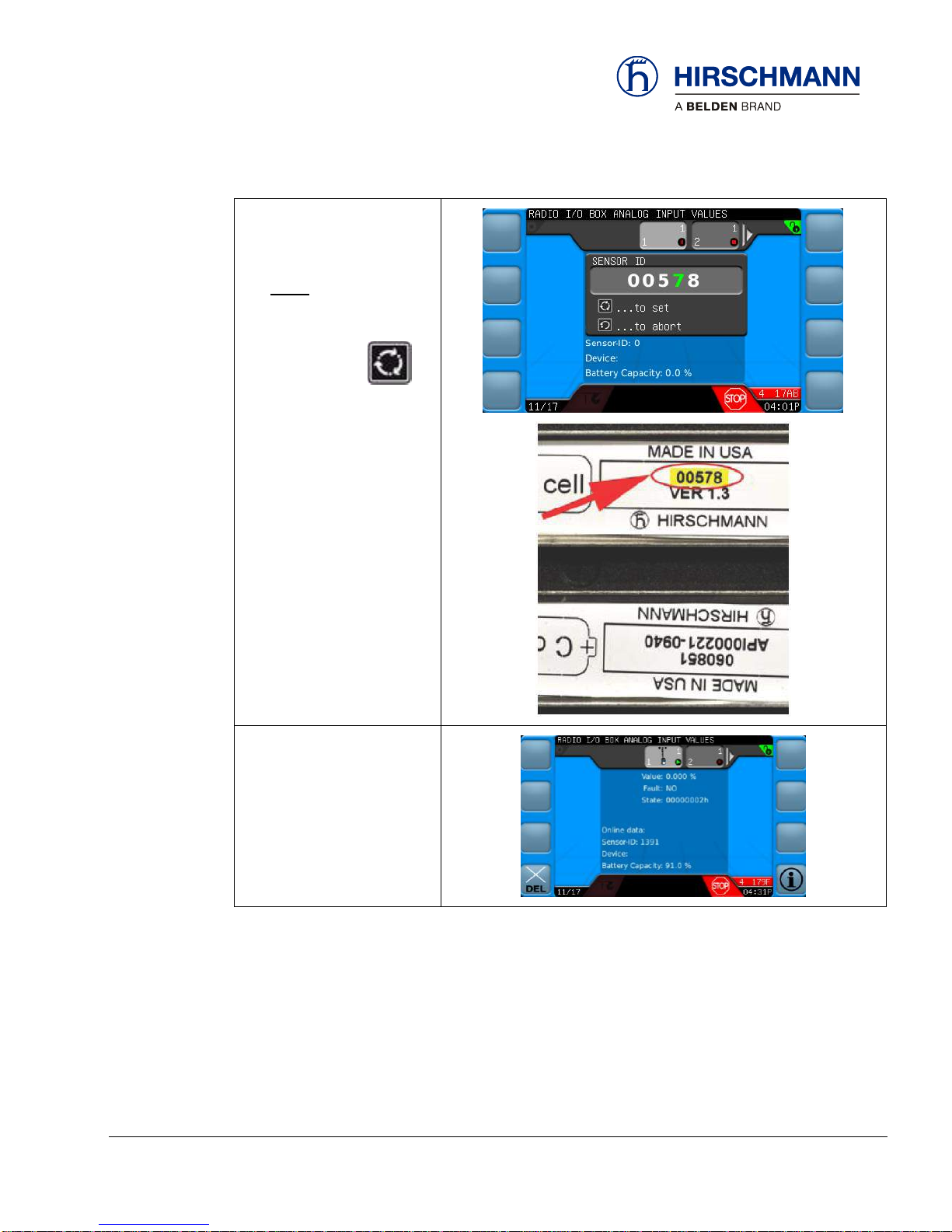
2. Enter the unique ID of the
sensor
NOTE: Unique ID is
found on battery terminal
3. Press the SET
when ID is entered correctly
4. Sensor is successfully
added
Page 57

Commissioning
© 2016 Hirschmann Automation and Control GmbH · Mobile Machine Control Solutions · www.beldensolutions.com 57/161
qSCALE i2 Cranes (Tool Version 3.0.34) Service Manual / Issue B / 11-2017 / ac.
4.2 Sensor Calibration
This section will explain how to calibrate the various sensors used in the qSCALE i2 System.
When the system is first turned on system may prompt the user to calibrate sensors.
Press the SET button to continue to the configure operation mode screen. The Configure Operation Mode Screen will show “Unready System! No Operation!” until all required sensors are calibrated.
IMPORTANT
The RCL is an operating aid that warns the crane operator of imminent overloading or of the
approach of the hook block to the boom head in order to avoid possible property damage or
injury to personnel.
The device is not, nor is it intended to be, a substitute for good operator judgment and/or experience. It does not remove the need for utilizing only recognized safe procedures during crane
operations.
Page 58

Commissioning
© 2016 Hirschmann Automation and Control GmbH · Mobile Machine Control Solutions · www.beldensolutions.com 58/161
qSCALE i2 Cranes (Tool Version 3.0.34) Service Manual / Issue B / 11-2017 / ac.
CAUTION
The crane operator continues to bear ultimate responsibility for safe operation of the crane. The
operator must ensure that he fully understands and follows the displayed notes and instructions
in their entirety.
WARNING
The RCL is not able to provide aid to the crane operator unless it has been properly adjusted
and the correct load capacity chart and the correct operating code have been entered for the
respective rigging configuration. The correctness of the RCL settings must be guaranteed before beginning crane work in order to avoid damage to property and severe or even fatal injuries
to personnel.
WARNING
This system can be equipped with an external key-operated switch located in the crane operator's location. This key-operated switch overrides control lever function switch-off by the RCL or
by the hoist limit switch system. This switch may only be used during emergency situations,
and even then, only by authorized personnel. Failure to observe these instructions could result
in damage to property and severe or even fatal injuries to personnel.
WARNING
The RCL cannot perform correctly unless it has been properly adjusted. The prerequisite for this
is making conscientious and correct entries during the set-up procedure in accordance with the
actual configuration of the crane. The correctness of the RCL settings must be ensured before
beginning crane work in order to avoid damage to property and severe or even fatal injuries to
personnel.
NOTE
The calibration menu functions are password protected by an RCL or System password.
Page 59

Commissioning
© 2016 Hirschmann Automation and Control GmbH · Mobile Machine Control Solutions · www.beldensolutions.com 59/161
qSCALE i2 Cranes (Tool Version 3.0.34) Service Manual / Issue B / 11-2017 / ac.
NOTE
CAN Pressure Transducers do not need to be calibrated!
Page 60

Commissioning
© 2016 Hirschmann Automation and Control GmbH · Mobile Machine Control Solutions · www.beldensolutions.com 60/161
qSCALE i2 Cranes (Tool Version 3.0.34) Service Manual / Issue B / 11-2017 / ac.
4.2.1 Sensor Calibration Selection
Calibration for sensors is selected under the settings menu. To calibrate sensors a RCL a system
password is required. See Section 6.1 for password entry.
Information Selection Menu allows the user to view crane, sensor, and software version information and
is the starting point for diagnostic information.
MAIN
WORKING
SCREEN
OP-MODE
CONFIRM
SETUP
SENSOR
CALIBRATION
Do not calibrate!
CAN Pressure Transducers do
not need to be calibrated.
Angle Sensor Calibration
(See Section 3.1.2.2.3)
Length Sensor Calibration
(See Section 3.1.2.2.4)
Slew Sensor Calibration
(See Section 4.2.4)
Tilt Sensor Calibration
(See Section 4.2.5)
Function Keys
Page 61

Commissioning
© 2016 Hirschmann Automation and Control GmbH · Mobile Machine Control Solutions · www.beldensolutions.com 61/161
qSCALE i2 Cranes (Tool Version 3.0.34) Service Manual / Issue B / 11-2017 / ac.
4.2.2 Boom Length Calibration
This section describes how to calibrate the boom length sensor.
MAIN
WORKING
SCREEN
OP-MODE
CONFIRM
SETUP
SENSOR
CALIBRATION
BOOM
LENGTH
IMPORTANT
The crane must be on a level surface and outriggers properly positioned to calibrate this sensor.
The boom must also be at an angle where it can fully extend and remain within allowable load
chart values.
5. Fully retract the boom.
6. Press the SET button to confirm this
is completed.
7. The OK on the screen should now be green.
8. Press the SET button to confirm this
is completed.
Instructions
Page 62

Commissioning
© 2016 Hirschmann Automation and Control GmbH · Mobile Machine Control Solutions · www.beldensolutions.com 62/161
qSCALE i2 Cranes (Tool Version 3.0.34) Service Manual / Issue B / 11-2017 / ac.
9. Fully extend the boom (check the load chart of
the machine to find a safe configuration for fully extending the boom).
10. Press the SET button to confirm this
is completed.
11. The OK on the screen should now be green.
12. Press the SET button to confirm this
is completed.
13. Length Sensor Calibration is complete.
Page 63

Commissioning
© 2016 Hirschmann Automation and Control GmbH · Mobile Machine Control Solutions · www.beldensolutions.com 63/161
qSCALE i2 Cranes (Tool Version 3.0.34) Service Manual / Issue B / 11-2017 / ac.
4.2.3 Boom Angle Calibration
This section describes how to calibrate the boom angle sensor.
MAIN
WORKING
SCREEN
OP-MODE
CONFIRM
SETUP
SENSOR
CALIBRATION
BOOM
ANGLE
IMPORTANT
The crane must be on a level surface and outriggers properly positioned to calibrate this sensor.
1. Fully retract the boom
2. Press the SET button to confirm this
is completed.
3. Lower the boom to a near zero degree value.
4. Press the SET button to confirm this
is completed.
Instructions
Page 64

Commissioning
© 2016 Hirschmann Automation and Control GmbH · Mobile Machine Control Solutions · www.beldensolutions.com 64/161
qSCALE i2 Cranes (Tool Version 3.0.34) Service Manual / Issue B / 11-2017 / ac.
5. Use a digital inclinometer to measure the actual boom angle.
6. Press the SET button to confirm this
is completed.
7. Enter the measured angle from Step 5.
a. Rotate the rotary encoder clockwise to in-
crease the digit (negative and decimal
points available for selection)
b. Rotate the rotary encoder counter clock-
wise to decrease the selected digit (negative and decimal points available for selection
c. Press the rotary encoder to advance to the
next digit
8. Press the SET button to confirm this
is completed.
9. Raise the boom to a higher angle (closer to
maximum angle is better).
10. Press the SET button to confirm this
is completed.
Page 65

Commissioning
© 2016 Hirschmann Automation and Control GmbH · Mobile Machine Control Solutions · www.beldensolutions.com 65/161
qSCALE i2 Cranes (Tool Version 3.0.34) Service Manual / Issue B / 11-2017 / ac.
11. Use a digital inclinometer to measure the actual boom angle.
12. Press the SET button to confirm this
is completed.
13. Enter the measured angle from Step 5.
a. Rotate the rotary encoder clockwise to in-
crease the digit (negative and decimal
points available for selection)
b. Rotate the rotary encoder counter clock-
wise to decrease the selected digit (negative and decimal points available for selection
c. Press the rotary encoder to advance to the
next digit
14. Press the SET button to confirm this
is completed.
Page 66

Commissioning
© 2016 Hirschmann Automation and Control GmbH · Mobile Machine Control Solutions · www.beldensolutions.com 66/161
qSCALE i2 Cranes (Tool Version 3.0.34) Service Manual / Issue B / 11-2017 / ac.
4.2.4 Slew Sensor Calibration
This section describes how to calibrate the slew angle sensor.
MAIN
WORKING
SCREEN
OP-MODE
CONFIRM
SETUP
SENSOR
CALIBRATION
SLEW
ANGLE
IMPORTANT
The crane must be on a level surface and outriggers properly positioned to calibrate this sensor.
1. Move the boom to 0° slew
2. Press the SET button to confirm
this is completed.
3. It must be confirmed a second time that
the boom is moved to the front of the machine.
4. Press the SET button to confirm
this is completed.
Instructions
Page 67

Commissioning
© 2016 Hirschmann Automation and Control GmbH · Mobile Machine Control Solutions · www.beldensolutions.com 67/161
qSCALE i2 Cranes (Tool Version 3.0.34) Service Manual / Issue B / 11-2017 / ac.
5. Slew the boom clockwise at least 5° (maximum 80°)
6. Press the SET button to confirm
this is completed.
7. It must be confirmed a second time that
the boom is moved to the front of the machine.
8. Press the SET button to confirm
this is completed.
Page 68

Commissioning
© 2016 Hirschmann Automation and Control GmbH · Mobile Machine Control Solutions · www.beldensolutions.com 68/161
qSCALE i2 Cranes (Tool Version 3.0.34) Service Manual / Issue B / 11-2017 / ac.
4.2.5 Tilt Sensor Calibration
This section describes how to calibrate the tilt angle sensor.
MAIN
WORKING
SCREEN
OP-MODE
CONFIRM
SETUP
SENSOR
CALIBRATION
TILT ANGLE
IMPORTANT
The crane must be on a level surface and outriggers properly positioned to calibrate this sensor.
9. Level the machine
10. Move the boom to the front of the machine
11. Press the SET button to confirm
this is completed.
12. It must be confirmed a second time that
the boom is moved to the front of the machine.
13. Press the SET button to confirm
this is completed.
Instructions
Page 69

Commissioning
© 2016 Hirschmann Automation and Control GmbH · Mobile Machine Control Solutions · www.beldensolutions.com 69/161
qSCALE i2 Cranes (Tool Version 3.0.34) Service Manual / Issue B / 11-2017 / ac.
14. Slew the boom 90° (making the machine
horizontal)
15. Press the SET button to confirm
this is completed.
16. It must be confirmed a second time that
the machine is horizontal.
17. Press the SET button to confirm
this is completed.
18. Confirm that the machine is level in the X
and Y directions.
19. Press the SET button to confirm
this is completed.
20. Tilt the machine 3° to the rear by retracting the rear outriggers and/or extending
the front outriggers.
21. Press the SET button to confirm
this is completed.
22. It must be confirmed a second time that
the machine is tilted to the rear.
23. Press the SET button to confirm
this is completed.
Page 70

Commissioning
© 2016 Hirschmann Automation and Control GmbH · Mobile Machine Control Solutions · www.beldensolutions.com 70/161
qSCALE i2 Cranes (Tool Version 3.0.34) Service Manual / Issue B / 11-2017 / ac.
24. Tilt the machine to the right by retracting
the right outriggers and/or extending the
left outriggers.
25. Press the SET button to confirm
this is completed.
26. It must be confirmed a second time that
the machine is tilted to the right.
27. Press the SET button to confirm
this is completed.
28. Finish the calibration by pressing the SET
button.
Page 71

Commissioning
© 2016 Hirschmann Automation and Control GmbH · Mobile Machine Control Solutions · www.beldensolutions.com 71/161
qSCALE i2 Cranes (Tool Version 3.0.34) Service Manual / Issue B / 11-2017 / ac.
4.2.6 Analog Outrigger Calibration
This section is only for models with Analog Outrigger Length Sensors. Unlike the length and angles
sensors, calibration for outriggers is done through the Analog Input Screen.
MAIN
WORKING
SCREEN
OP-MODE
CONFIRM
INFORMATION
SELECTION
SENSOR
INFORMATION
ANALOG
INPUTS
1. Fully retract the outriggers
2. Press the function button to set the scale start.
Page 72

Commissioning
© 2016 Hirschmann Automation and Control GmbH · Mobile Machine Control Solutions · www.beldensolutions.com 72/161
qSCALE i2 Cranes (Tool Version 3.0.34) Service Manual / Issue B / 11-2017 / ac.
3. Fully extend the outriggers
4. Retract the outriggers ~1”
5. Press the function button to set the scale end.
6. Fully extend the outriggers for
operation.
NOTE
This has to be performed for all analog outriggers, if equipped
Page 73

Maintenance and Repair
© 2016 Hirschmann Automation and Control GmbH · Mobile Machine Control Solutions · www.beldensolutions.com 73/161
qSCALE i2 Cranes (Tool Version 3.0.34) Service Manual / Issue B / 11-2017 / ac.
5 Maintenance and Repair
5.1 Maintenance
The qSCALE i2 operating console contains no wearing parts and therefore cannot be opened. If malfunctions are noticed or differences between actual and displayed measured values, switch the device
off and have it checked and, if necessary, repaired immediately by an authorized Hirschmann service
partner.
5.2 Cleaning
Clean the surface and the front screen of the device occasionally with a damp cloth and a mild detergent. Never use abrasive or aggressive detergents as these may damage the device.
IMPORTANT
Device may be damaged by the use of high-pressure washer.
The device must not be treated with high-pressure cleaner or similarly aggressive methods un-
der any circumstances!
Page 74

Maintenance and Repair
© 2016 Hirschmann Automation and Control GmbH · Mobile Machine Control Solutions · www.beldensolutions.com 74/161
qSCALE i2 Cranes (Tool Version 3.0.34) Service Manual / Issue B / 11-2017 / ac.
5.3 qSCALE i2 Console Software Upload
This section will instruct how to upload software into a qSCALE i2 Console.
NOTE
Item needed: 2 GB or less USB flash drive.
1. Ensure the qSCALE i2 system is turned off (crane ignition key turned to the “OFF” position)
2. Insert the USB flash drive with the software loaded into the USB port on the qSCALE i2
console (the USB port is located behind the rubber flap to the left and below the selection
knob.
3. Press and hold the top two function keys on the left side and turn the system ON (crane
ignition key turned to “on” or ACCY” position). Continue to hold for an additional 10 seconds to ensure system recognizes the selection.
Instructions
USB Port
Press and hold
top two function
keys during
power up
Page 75

Maintenance and Repair
© 2016 Hirschmann Automation and Control GmbH · Mobile Machine Control Solutions · www.beldensolutions.com 75/161
qSCALE i2 Cranes (Tool Version 3.0.34) Service Manual / Issue B / 11-2017 / ac.
4. The system will now begin the uploading process. The screen will begin to display various
messages as the software loads. This process may take several minutes.
5. Once step 4 has been completed, the console will display the crane model and serial
number and then the home screen. The qSCALE i2 system may now be powered down
(crane ignition key turned to the “OFF” position).
6. The USB flash drive can now safely be removed. Replace the flap.
7. The software has now been uploaded and the system is ready for use.
Page 76

Appendix
© 2016 Hirschmann Automation and Control GmbH · Mobile Machine Control Solutions · www.beldensolutions.com 76/161
qSCALE i2 Cranes (Tool Version 3.0.34) Service Manual / Issue B / 11-2017 / ac.
6 Appendix
6.1 Password Entry
The password entry screen will appear when any menu attempted to be entered is password protected
and the system is not already unlocked.
There are two passwords:
Setup Password
Administrator Password
NOTE
Safety-relevant settings can only be carried out by authorized personnel after inputting a password (Service Code).
This prevents inadvertent changes being made to the settings.
Password entry is done by the following instructions:
When entering the screen, the first of the four digits will be highlighted in “green”
Turn the rotary knob to change the highlighted digit to the desired number
Once the green digit has changed to the correct number press the rotary knob to continue to
the second digit
Continue this process until all four digits have been entered
Press the SET key to enter the password. The previous menu will be displayed if the
password is entered incorrectly
Press the ESCAPE key to abort entry and return to the previous menu
Instructions
Page 77

Appendix
© 2016 Hirschmann Automation and Control GmbH · Mobile Machine Control Solutions · www.beldensolutions.com 77/161
qSCALE i2 Cranes (Tool Version 3.0.34) Service Manual / Issue B / 11-2017 / ac.
6.2 Error Code Tables
This section lists error codes reported by the qSCALE system along with their possible cause and solution.
The first one or two digits of an error code can determine what type of error is occurring
00xx
General Error
Other
Section 6.2.1
2xxx
Module Error
3xxx
Module Error
1Fxx
System
01xx
Limiter Error
Global Cut
Section 6.2.2
02xx
Single Cut
03xx
Error
04xx
Warning
05xx
Pre-Warning
0Axx
Kinematic Error
Kinematic
Section 6.2.3
11xx
CAN Error
Cable Break / Lower Limit
Section 6.2.4
12xx
Short-Circuit to Ground
13xx
Short-Circuit / Upper Limit
14xx
Module Error
15xx
Output Deactivated
16xx
Sensor Supply Voltage Error
17xx
Data Error / CAN Error
18xx
Timeout / CAN Timeout
19xx
Safety Error
1Axx
Parameter Error
1Bxx
Unspecified Error
1Cxx
Missing Adjustment
Page 78

Appendix
© 2016 Hirschmann Automation and Control GmbH · Mobile Machine Control Solutions · www.beldensolutions.com 78/161
qSCALE i2 Cranes (Tool Version 3.0.34) Service Manual / Issue B / 11-2017 / ac.
6.2.1 General Errors – 00xx, 1Fxx, 2xxx, & 3xxx
Error
Code
Description
Cause
Notice/Solution
0001
System started
Normal system start
Event logging message. Not an error
0002
System restarted
Normal system start instigated by Configuration Tool
Event logging message. Not an error
0011
Output system version
Unknown outcome / For information
Debugging log message. Not an error
0021
Output machine information
Unknown outcome / For information
Debugging log message. Not an error
0070
Cyclic Logger Update
Not Available
Not Available
0071
Overload Logger Update
Not Available
Not Available
0072
Invalid operating mode
Logger update
Not Available
Not Available
0073
Cyclic Logger Update
Not Available
Not Available
0081
Date set by user
Not Available
Not Available
0082
Time set by user
Not Available
Not Available
0090
Operating mode changed
Not Available
Not Available
00AA
Output debug information
Unknown outcome / For information
Debugging log message. Not an error
00FC
Controller Not Initialized
The system is waiting for the controller
to finish initializing
The error will clear when the system
finishes the initialization process
00FD
System Sleep Mode
Unknown outcome / For information
Event logging message. Not an error
00FE
System restarted after
deleting the application
Unknown outcome / For information
Event logging message. Not an error
00FF
System stopped
Normal system stop
Event logging message. Not an error
1F00
System Error
Fatal error or failure to initialize the
system
Turn the Ignition off and on again.
Consult Customer Service if the error
occurs again
1F01
Timeout
Console (HMI) communications failure
Check the bus cabling or connector.
Try turning the Ignition off and on
again. Consult Customer Service if the
error occurs again
1F02
Timeout
Kinematics communications failure
Turn the Ignition off and on again.
Consult Customer Service if the error
occurs again
1F03
Timeout
Limiter communications failure
Turn the Ignition off and on again.
Consult Customer Service if the error
occurs again
1F04
Timeout
Datalogger communications failure
Turn the Ignition off and on again.
Consult Customer Service if the error
occurs again
1F05
Timeout
Communications failure with external
system
Turn the Ignition off and on again.
Consult Customer Service if the error
occurs again
Page 79

Appendix
© 2016 Hirschmann Automation and Control GmbH · Mobile Machine Control Solutions · www.beldensolutions.com 79/161
qSCALE i2 Cranes (Tool Version 3.0.34) Service Manual / Issue B / 11-2017 / ac.
Error
Code
Description
Cause
Notice/Solution
1F06
Timeout
Communications failure with external
system
Turn the Ignition off and on again.
Consult Customer Service if the error
occurs again
1F07
Timeout
Communications failure with external
system
Turn the Ignition off and on again.
Consult Customer Service if the error
occurs again
1F08
Timeout
Communications failure with external
system
Turn the Ignition off and on again.
Consult Customer Service if the error
occurs again
1F10
Computer operation error
Internal error in the Application program
Turn the Ignition off and on again.
Consult Customer Service if the error
occurs again
1F11
Computer operation error
Internal error in the Application program
Turn the Ignition off and on again.
Consult Customer Service if the error
occurs again
1F12
Computer operation error
Internal error in the Application program
Turn the Ignition off and on again.
Consult Customer Service if the error
occurs again
1F13
Computer operation error
Internal error in the Application program
Turn the Ignition off and on again.
Consult Customer Service if the error
occurs again
1F14
Computer operation error
Internal error in the Application program
Turn the Ignition off and on again.
Consult Customer Service if the error
occurs again
1F15
Computer operation error
Internal error in the Application program
Turn the Ignition off and on again.
Consult Customer Service if the error
occurs again
1F16
Computer operation error
Internal error in the Application program
Turn the Ignition off and on again.
Consult Customer Service if the error
occurs again
1F17
Wrong data
The machine's data programming does
not fit the application
The system’s data is incorrectly displayed. Consult Customer Service if
the error occurs again
1F18
Serial Number wrong or
not set
Serial Number is not set or is invalid
Set Serial Number to valid entry
1F1F
Outputs deactivated
All enabled outputs are deactivated
Information: Subsequent errors resulting from another system error
1F2F
Outputs deactivated
All outputs are deactivated
Information: Subsequent errors resulting from another system error
1F30
Redundancy error
Disparity between feedback contact and
redundancy monitor
Turn the Ignition off and on again.
Consult Customer Service if the error
occurs again
1F31
Redundancy error
Error in redundancy system 1
Turn the Ignition off and on again.
Consult Customer Service if the error
occurs again
1F32
Redundancy error
Error in redundancy system 2
Turn the Ignition off and on again.
Consult Customer Service if the error
occurs again
Page 80

Appendix
© 2016 Hirschmann Automation and Control GmbH · Mobile Machine Control Solutions · www.beldensolutions.com 80/161
qSCALE i2 Cranes (Tool Version 3.0.34) Service Manual / Issue B / 11-2017 / ac.
Error
Code
Description
Cause
Notice/Solution
1F3F
Version Error
The versions of the load charts / data
programming are incompatible with the
application
Call Customer Service to have the unit
or software replaced
1F40
Power supply
System supply voltage is too Low
Check the battery voltage and the
power supply wiring
1F41
Battery voltage
Buffered battery voltage is too Low
Call Customer Service to have the unit
replaced
1F42
Warning temperature
Power supply temperature is too High
Check the system's installation. Try
turning the Ignition off and on again.
Consult Customer Service if the error
occurs again
1F43
Warning temperature
CPU temperature is too High
Check the system's installation. Try
turning the Ignition off and on again.
Consult Customer Service if the error
occurs again
1F44
CAN bus network error
CAN bus failure
Check the CAN cabling and supply
voltage. Try turning the Ignition off and
on again. Consult Customer Service if
the error occurs again
1F4F
Version Error
The versions of the parameter data and
the application are incompatible
Call Customer Service to have the unit
or software replaced
1FFF
Fatal safety error
Unrecoverable RAM or FLASH memory
failure - the system is unsafe
Turn the Ignition off and on again.
Consult Customer Service if the error
occurs again
2000
Module Error
Command line error
Turn the Ignition off and on again.
Consult Customer Service if the error
occurs again
2001
Module Error
Project - load failure
Turn the Ignition off and on again.
Consult Customer Service if the error
occurs again
2002
Module Error
Machine model - load failure
Turn the Ignition off and on again.
Consult Customer Service if the error
occurs again
2003
Module Error
Operating Mode - load failure
Turn the Ignition off and on again.
Consult Customer Service if the error
occurs again
2004
Module Error
Interface initialization failure
Turn the Ignition off and on again.
Consult Customer Service if the error
occurs again
2005
Module Error
Data read/write failure
Turn the Ignition off and on again.
Consult Customer Service if the error
occurs again
2010
Module Error
Operating mode selection error
Select a valid Operating Mode
2011
Module Error
Machine model selection error
Select a valid Operating Mode
2014
Module Error
Machine model selection error
Select a valid Operating Mode
2015
Module Error
Operating mode selection error
Select a valid Operating Mode
Page 81

Appendix
© 2016 Hirschmann Automation and Control GmbH · Mobile Machine Control Solutions · www.beldensolutions.com 81/161
qSCALE i2 Cranes (Tool Version 3.0.34) Service Manual / Issue B / 11-2017 / ac.
Error
Code
Description
Cause
Notice/Solution
2A10
Module Error
Internal module error (Null)
Turn the Ignition off and on again.
Consult Customer Service if the error
occurs again
2A11
Module Error
Internal module error (Zero ref.)
Turn the Ignition off and on again.
Consult Customer Service if the error
occurs again
2A12
Module Error
Internal module error (Ref. type)
Turn the Ignition off and on again.
Consult Customer Service if the error
occurs again
2EE5
Module Error
Unrecoverable RAM or FLASH memory
failure - the system is unsafe
Turn the Ignition off and on again.
Consult Customer Service if the error
occurs again
3001
Module Error
Data read/write failure
Turn the Ignition off and on again.
Consult Customer Service if the error
occurs again
3002
Module Error
Operating mode selection error - mode
is ignored
Turn the Ignition off and on again.
Consult Customer Service if the error
occurs again
3003
Module Error
Operating mode selection error
Select a valid Operating Mode
3004
Module Error
No valid Rated Load found
Select a valid Operating Mode and
operate within a valid Working Range
(load chart)
3005
Module Error
Operating mode selection error - mode
is void
Turn the Ignition off and on again.
Consult Customer Service if the error
occurs again
3006
Module Error
Unrecoverable RAM or FLASH memory
failure - the system is unsafe
Turn the Ignition off and on again.
Consult Customer Service if the error
occurs again
3007
Machine outside of Working Range
No load tables available because the
machine is outside the working limits
Return to the permitted Working
Range (load chart)
5001
Boom Length Calculation
Error
The Length Measurement is invalid
Check cable-reel mounting
Table 8 - 1
Page 82

Appendix
© 2016 Hirschmann Automation and Control GmbH · Mobile Machine Control Solutions · www.beldensolutions.com 82/161
qSCALE i2 Cranes (Tool Version 3.0.34) Service Manual / Issue B / 11-2017 / ac.
6.2.2 Limit Error Codes – 01xx, 02xx, 03xx, 04xx, & 05xx
The first two (2) digits of a limit error code signify the function of a given error.
01xx Global Cut
02xx Single Cut
03xx Error
04xx Warning
05xx Pre-Warning
Error
Code
Description
Cause
Notice/Solutions
0100
Global Cut
Min radius limit underrun
Booming up inside the load
chart's inner radius limit
Boom down to a valid load-chart
radius and angle
0200
Single Cut
0300
Error
0400
Warning
0500
Pre-Warning
0101
Global Cut
Max radius limit exceeded
Booming down outside the
load chart's outer radius
limit
Boom up to a valid load-chart radius
and angle
0201
Single Cut
0301
Error
0401
Warning
0501
Pre-Warning
0102
Global Cut
Main boom angle too
low
Booming down below the
load chart's lower angle
limit
Boom up to a valid load-chart radius
and angle
0202
Single Cut
0302
Error
0402
Warning
0502
Pre-Warning
0103
Global Cut
Main boom angle too
high
Booming up beyond the
load chart's upper angle
limit
Boom down to a valid load-chart
radius and angle
0203
Single Cut
0303
Error
0403
Warning
0503
Pre-Warning
0104
Global Cut
Jib angle limit underrun
Booming down below the
load chart's lower angle
limit
Move the jib up to a load chart
permissible radius or angle
0204
Single Cut
0304
Error
0404
Warning
0504
Pre-Warning
0105
Global Cut
Jib angle limit exceeded
Booming up beyond the
load chart's upper angle
limit
Move the jib down to a load chart
permissible radius or angle
0205
Single Cut
0305
Error
0405
Warning
0505
Pre-Warning
0106
Global Cut
Jib angle limit underrun
Booming down below the
load chart's lower angle
limit
Move the jib up to a load chart
permissible radius or angle
0206
Single Cut
0306
Error
0406
Warning
0506
Pre-Warning
0107
Global Cut
Jib angle limit exceeded
Booming up beyond the
load chart's upper angle
limit
Move the jib down to a load chart
permissible radius or angle
0207
Single Cut
0307
Error
0407
Warning
0507
Pre-Warning
010A
Global Cut
Slew angle left to large
Slewing outside the Working Range
Return to the permitted Working
Range (load chart)
020A
Single Cut
030A
Error
040A
Warning
050A
Pre-Warning
Page 83

Appendix
© 2016 Hirschmann Automation and Control GmbH · Mobile Machine Control Solutions · www.beldensolutions.com 83/161
qSCALE i2 Cranes (Tool Version 3.0.34) Service Manual / Issue B / 11-2017 / ac.
Error
Code
Description
Cause
Notice/Solutions
010B
Global Cut
Slew angle right to large
Slewing outside the Working Range
Return to the permitted Working
Range (load chart)
020B
Single Cut
030B
Error
040B
Warning
050B
Pre-Warning
010C
Global Cut
Min length limit underrun
Telescoping below the
Working Range
Telescope into the permitted Working Range (load chart)
020C
Single Cut
030C
Error
040C
Warning
050C
Pre-Warning
010D
Global Cut
Max length limit exceeded
Telescoping beyond the
Working Range
Telescope into the permitted Working Range (load chart)
020D
Single Cut
030D
Error
040D
Warning
050D
Pre-Warning
010E
Global Cut
Min height limit underrun
Descending below the
Working Range
Move the boom into the permitted
Working Range (load chart)
020E
Single Cut
030E
Error
040E
Warning
050E
Pre-Warning
010F
Global Cut
Max height limit exceeded
Elevating above the Working Range
Move the boom into the permitted
Working Range (load chart)
020F
Single Cut
030F
Error
040F
Warning
050F
Pre-Warning
0110
Global Cut
Min wind speed limit
underrun
Exceptionally Low Wind
Speed
Operation is restricted to permitted
conditions (load chart)
0210
Single Cut
0310
Error
0410
Warning
0510
Pre-Warning
0111
Global Cut
Max wind speed limit
exceeded
Excessively High Wind
Speed
Operation is restricted to permitted
conditions (load chart)
0211
Single Cut
0311
Error
0411
Warning
0511
Pre-Warning
0112
Global Cut
Min temperature limit
underrun
Excessively Low ambient
Temperature
Operation is restricted to permitted
conditions (load chart)
0212
Single Cut
0312
Error
0412
Warning
0512
Pre-Warning
0113
Global Cut
Max temperature limit
exceeded
Excessively High ambient
Temperature
Operation is restricted to permitted
conditions (load chart)
0213
Single Cut
0313
Error
0413
Warning
0513
Pre-Warning
0120
Global Cut
Min radius limit underrun
Boom up within the radius
inner limit (Load-chart /
'Grey Zone' pre-warning)
Boom down to a valid load-chart
radius and angle
0220
Single Cut
0320
Error
0420
Warning
0520
Pre-Warning
0121
Global Cut
Max radius limit exceeded
Boom down outside the
radius outer limit (Loadchart / 'Grey Zone' prewarning)
Boom up to a valid load-chart radius
and angle
0221
Single Cut
0321
Error
0421
Warning
0521
Pre-Warning
Page 84

Appendix
© 2016 Hirschmann Automation and Control GmbH · Mobile Machine Control Solutions · www.beldensolutions.com 84/161
qSCALE i2 Cranes (Tool Version 3.0.34) Service Manual / Issue B / 11-2017 / ac.
Error
Code
Description
Cause
Notice/Solutions
0122
Global Cut
Main boom angle too
low
Boom down within the
radius inner limit (Loadchart / 'Grey Zone' prewarning)
Boom up to a valid load-chart radius
and angle
0222
Single Cut
0322
Error
0422
Warning
0522
Pre-Warning
0123
Global Cut
Main boom angle too
high
Boom up beyond the
radius outer limit (Loadchart / 'Grey Zone' prewarning)
Boom down to a valid load-chart
radius and angle
0223
Single Cut
0323
Error
0423
Warning
0523
Pre-Warning
0124
Global Cut
Jib angle limit underrun
Boom down within the
radius inner limit (Loadchart / 'Grey Zone' prewarning)
Move the jib up to a load chart
permissible radius or angle
0224
Single Cut
0324
Error
0424
Warning
0524
Pre-Warning
0125
Global Cut
Jib angle limit exceeded
Boom up beyond the
radius outer limit (Loadchart / 'Grey Zone' prewarning)
Move the jib down to a load chart
permissible radius or angle
0225
Single Cut
0325
Error
0425
Warning
0525
Pre-Warning
0126
Global Cut
Jib angle limit underrun
Boom down within the
radius inner limit (Loadchart / 'Grey Zone' prewarning)
Move the jib up to a load chart
permissible radius or angle
0226
Single Cut
0326
Error
0426
Warning
0526
Pre-Warning
0127
Global Cut
Jib angle limit exceeded
Boom up beyond the
radius outer limit (Loadchart / 'Grey Zone' prewarning)
Move the jib down to a load chart
permissible radius or angle
0227
Single Cut
0327
Error
0427
Warning
0527
Pre-Warning
012A
Global Cut
Slew angle left to large
Slewing outside the Working Range (Pre-warning /
'Grey Zone')
Return to the permitted Working
Range (load chart)
022A
Single Cut
032A
Error
042A
Warning
052A
Pre-Warning
012B
Global Cut
Slew angle right to large
Slewing outside the Working Range (Pre-warning /
'Grey Zone')
Return to the permitted Working
Range (load chart)
022B
Single Cut
032B
Error
042B
Warning
052B
Pre-Warning
012C
Global Cut
Min length limit underrun
Retracting within the innermost Working Range
limit (Pre-warning / 'Grey
Zone')
Telescope into the permitted Working Range (load chart)
022C
Single Cut
032C
Error
042C
Warning
052C
Pre-Warning
012D
Global Cut
Max length limit exceeded
Extending outside the
Working Range (Prewarning / 'Grey Zone')
Telescope into the permitted Working Range (load chart)
022D
Single Cut
032D
Error
042D
Warning
052D
Pre-Warning
012E
Global Cut
Min height limit underrun
Descending below the
Working Range (Prewarning / 'Grey Zone')
Move the boom into the permitted
Working Range (load chart)
022E
Single Cut
032E
Error
042E
Warning
052E
Pre-Warning
Page 85

Appendix
© 2016 Hirschmann Automation and Control GmbH · Mobile Machine Control Solutions · www.beldensolutions.com 85/161
qSCALE i2 Cranes (Tool Version 3.0.34) Service Manual / Issue B / 11-2017 / ac.
Error
Code
Description
Cause
Notice/Solutions
012F
Global Cut
Max height limit exceeded
Elevating above the Working Range (Pre-warning /
'Grey Zone')
Move the boom into the permitted
Working Range (load chart)
022F
Single Cut
032F
Error
042F
Warning
052F
Pre-Warning
0130
Global Cut
Min wind speed limit
underrun
Excessively Low Wind
Speed (Pre-warning / 'Grey
Zone')
Operation is restricted to permitted
conditions (load chart)
0230
Single Cut
0330
Error
0430
Warning
0530
Pre-Warning
0131
Global Cut
Max wind speed limit
exceeded
Excessively High Wind
Speed (Pre-warning / 'Grey
Zone')
Operation is restricted to permitted
conditions (load chart)
0231
Single Cut
0331
Error
0431
Warning
0531
Pre-Warning
0132
Global Cut
Min temperature limit
underrun
Excessively Low ambient
Temperature (Pre-warning
/ 'Grey Zone')
Operation is restricted to permitted
conditions (load chart)
0232
Single Cut
0332
Error
0432
Warning
0532
Pre-Warning
0133
Global Cut
Max temperature limit
exceeded
Excessively High ambient
Temperature (Pre-warning
/ 'Grey Zone')
Operation is restricted to permitted
conditions (load chart)
0233
Single Cut
0333
Error
0433
Warning
0533
Pre-Warning
0140
Global Cut
Min radius limit underrun
Booming up beyond the
inner radius limit (user
preset- HMI or external
control)
Move the Jib down to a valid radius
and angle
0240
Single Cut
0340
Error
0440
Warning
0540
Pre-Warning
0141
Global Cut
Max radius limit exceeded
Booming down outside the
upper radius limit (user
preset - HMI or external
control)
Boom up to a valid radius and angle
0241
Single Cut
0341
Error
0441
Warning
0541
Pre-Warning
0142
Global Cut
Main boom angle too
low
Booming down below the
lower angle limit (user
preset- HMI or external
control)
Boom up to a valid radius and angle
0242
Single Cut
0342
Error
0442
Warning
0542
Pre-Warning
0143
Global Cut
Main boom angle too
high
Booming up beyond the
upper angle limit (user
preset- HMI or external
control)
Move the Jib down to a valid radius
and angle
0243
Single Cut
0343
Error
0443
Warning
0543
Pre-Warning
0144
Global Cut
Jib angle limit underrun
Booming down below the
lower angle limit (user
preset- HMI or external
control)
Move the jib up to a valid radius or
angle
0244
Single Cut
0344
Error
0444
Warning
0544
Pre-Warning
0145
Global Cut
Jib angle limit exceeded
Booming up beyond the
user upper angle limit (HMI
or external control)
Move the jib down to a valid radius
or angle
0245
Single Cut
0345
Error
0445
Warning
0545
Pre-Warning
Page 86

Appendix
© 2016 Hirschmann Automation and Control GmbH · Mobile Machine Control Solutions · www.beldensolutions.com 86/161
qSCALE i2 Cranes (Tool Version 3.0.34) Service Manual / Issue B / 11-2017 / ac.
Error
Code
Description
Cause
Notice/Solutions
0146
Global Cut
Jib angle limit underrun
Booming down below the
lower angle limit (user
preset- HMI or external
control)
Move the jib up to a valid radius or
angle
0246
Single Cut
0346
Error
0446
Warning
0546
Pre-Warning
0147
Global Cut
Jib angle limit exceeded
Booming up beyond the
user upper angle limit (HMI
or external control)
Move the jib down to a valid radius
or angle
0247
Single Cut
0347
Error
0447
Warning
0547
Pre-Warning
014A
Global Cut
Slew angle left to large
Slewing outside the Working Range limit (user prewarning - HMI or external
control)
Rotate to the permitted Working
Range
024A
Single Cut
034A
Error
044A
Warning
054A
Pre-Warning
014B
Global Cut
Slew angle right to large
Slewing outside the Working Range limit (user prewarning - HMI or external
control)
Rotate to the permitted Working
Range
024B
Single Cut
034B
Error
044B
Warning
054B
Pre-Warning
014C
Global Cut
Min length limit underrun
Retracting below the Working Range limit (user prewarning - HMI or external
control)
Telescope into the permitted Working Range
024C
Single Cut
034C
Error
044C
Warning
054C
Pre-Warning
014D
Global Cut
Max length limit exceeded
Extending outside the
Working Range limit (user
pre-warning - HMI or external control)
Telescope into the permitted Working Range
024D
Single Cut
034D
Error
044D
Warning
054D
Pre-Warning
014E
Global Cut
Min height limit underrun
Descending below the
Working Range limit (user
pre-warning - HMI or external control)
Move the boom into the permitted
Working Range (load chart)
024E
Single Cut
034E
Error
044E
Warning
054E
Pre-Warning
014F
Global Cut
Max height limit exceeded
Elevation above the user
limit (HMI or external
control)
Move the boom into the permitted
Working Range
024F
Single Cut
034F
Error
044F
Warning
054F
Pre-Warning
0150
Global Cut
Min wind speed limit
underrun
Wind Speed below the
lower user limit (HMI or
external control)
Operation is restricted to permitted
conditions
0250
Single Cut
0350
Error
0450
Warning
0550
Pre-Warning
0151
Global Cut
Max wind speed limit
exceeded
Wind Speed above the
upper user limit (HMI or
external control)
Operation is restricted to permitted
conditions
0251
Single Cut
0351
Error
0451
Warning
0551
Pre-Warning
0152
Global Cut
Min temperature limit
underrun
Ambient temperature
below the lower user limit
(HMI or external control)
Operation is restricted to permitted
conditions
0252
Single Cut
0352
Error
0452
Warning
0552
Pre-Warning
Page 87

Appendix
© 2016 Hirschmann Automation and Control GmbH · Mobile Machine Control Solutions · www.beldensolutions.com 87/161
qSCALE i2 Cranes (Tool Version 3.0.34) Service Manual / Issue B / 11-2017 / ac.
Error
Code
Description
Cause
Notice/Solutions
0153
Global Cut
Max temperature limit
exceeded
Ambient temperature
above the upper user limit
(HMI or external control)
Operation is restricted to permitted
conditions
0253
Single Cut
0353
Error
0453
Warning
0553
Pre-Warning
0160
Global Cut
Min radius limit underrun
Booming up beyond the
inner radius limit (user prewarning preset / 'Grey
Zone' - HMI or external
control)
Move the Jib down to a valid radius
and angle
0260
Single Cut
0360
Error
0460
Warning
0560
Pre-Warning
0161
Global Cut
Max radius limit exceeded
Booming down outside the
radius limit (user prewarning preset / 'Grey
Zone' - HMI or external
control)
Boom up to a valid radius and angle
0261
Single Cut
0361
Error
0461
Warning
0561
Pre-Warning
0162
Global Cut
Main boom angle too
low
Booming down below the
lower angle limit (user prewarning preset / 'Grey
Zone' - HMI or external
control)
Boom up to a valid radius and angle
0262
Single Cut
0362
Error
0462
Warning
0562
Pre-Warning
0163
Global Cut
Main boom angle too
high
Booming up beyond the
upper angle limit (user prewarning preset / 'Grey
Zone' - HMI or external
control)
Move the Jib down to a valid radius
and angle
0263
Single Cut
0363
Error
0463
Warning
0563
Pre-Warning
0164
Global Cut
Jib angle limit underrun
Booming down below the
lower angle limit (user prewarning preset / 'Grey
Zone' - HMI or external
control)
Move the jib up to a valid radius or
angle
0264
Single Cut
0364
Error
0464
Warning
0564
Pre-Warning
0165
Global Cut
Jib angle limit exceeded
Booming up beyond the
upper angle limit (user prewarning / 'Grey Zone' HMI or external control)
Move the jib down to a valid radius
or angle
0265
Single Cut
0365
Error
0465
Warning
0565
Pre-Warning
0166
Global Cut
Jib angle limit underrun
Booming down below the
lower angle limit (user prewarning preset / 'Grey
Zone' - HMI or external
control)
Move the jib up to a valid radius or
angle
0266
Single Cut
0366
Error
0466
Warning
0566
Pre-Warning
0167
Global Cut
Jib angle limit exceeded
Booming up beyond the
upper angle limit (user prewarning / 'Grey Zone' HMI or external control)
Move the jib down to a valid radius
or angle
0267
Single Cut
0367
Error
0467
Warning
0567
Pre-Warning
016A
Global Cut
Slew angle left to large
Slewing outside the Working Range limit (user prewarning / 'Grey Zone' HMI or external control)
Rotate to the permitted Working
Range
026A
Single Cut
036A
Error
046A
Warning
056A
Pre-Warning
016B
Global Cut
Slew angle right to large
Slewing outside the Working Range limit (user prewarning / 'Grey Zone' HMI or external control)
Rotate to the permitted Working
Range
026B
Single Cut
036B
Error
046B
Warning
056B
Pre-Warning
Page 88

Appendix
© 2016 Hirschmann Automation and Control GmbH · Mobile Machine Control Solutions · www.beldensolutions.com 88/161
qSCALE i2 Cranes (Tool Version 3.0.34) Service Manual / Issue B / 11-2017 / ac.
Error
Code
Description
Cause
Notice/Solutions
016C
Global Cut
Min length limit underrun
Telescoping below the
Working Range limit (user
pre-warning / 'Grey Zone' HMI or external control)
Telescope into the permitted Working Range
026C
Single Cut
036C
Error
046C
Warning
056C
Pre-Warning
016D
Global Cut
Max length limit exceeded
Telescoping beyond the
Working Range limit (user
pre-warning / 'Grey Zone' HMI or external control)
Telescope into the permitted Working Range
026D
Single Cut
036D
Error
046D
Warning
056D
Pre-Warning
016E
Global Cut
Min height limit underrun
Descending below the
Working Range limit (user
pre-warning / 'Grey Zone' HMI or external control)
Move the boom into the permitted
Working Range (load chart)
026E
Single Cut
036E
Error
046E
Warning
056E
Pre-Warning
016F
Global Cut
Max height limit exceeded
Elevation above the user
Working Range limit - User
pre-warning / 'Grey Zone'
Move the boom into the permitted
Working Range
026F
Single Cut
036F
Error
046F
Warning
056F
Pre-Warning
0170
Global Cut
Min wind speed limit
underrun
Wind Speed below the
lower limit (user prewarning / 'Grey Zone' -HMI
or external control)
Operation is restricted to permitted
conditions
0270
Single Cut
0370
Error
0470
Warning
0570
Pre-Warning
0171
Global Cut
Max wind speed limit
exceeded
Wind Speed above the
upper limit (user prewarning / 'Grey Zone' HMI or external control)
Operation is restricted to permitted
conditions
0271
Single Cut
0371
Error
0471
Warning
0571
Pre-Warning
0172
Global Cut
Min temperature limit
underrun
Ambient temperature
below the lower limit (user
pre-warning / 'Grey Zone' HMI or external control)
Operation is restricted to permitted
conditions
0272
Single Cut
0372
Error
0472
Warning
0572
Pre-Warning
0173
Global Cut
Max temperature limit
exceeded
Ambient temperature
above the upper limit (user
pre-warning / 'Grey Zone' HMI or external control)
Operation is restricted to permitted
conditions
0273
Single Cut
0373
Error
0473
Warning
0573
Pre-Warning
0174
Global Cut
Superstructure Inclination
The superstructure has
exceeded the maximum
inclination angle
Relevel the superstructure
0274
Single Cut
0374
Error
0474
Warning
0574
Pre-Warning
01A0
Global Cut
Min load limit on outrigger underrun front left
Load on Outrigger too Low
(tilting danger)
Move the boom into the permitted
Working Range (load chart)
02A0
Single Cut
03A0
Error
04A0
Warning
05A0
Pre-Warning
01A1
Global Cut
Max load limit on outrigger reached front left
Load on Outrigger too High
(outrigger damage)
Move the boom into the permitted
Working Range (load chart)
02A1
Single Cut
03A1
Error
04A1
Warning
05A1
Pre-Warning
Page 89

Appendix
© 2016 Hirschmann Automation and Control GmbH · Mobile Machine Control Solutions · www.beldensolutions.com 89/161
qSCALE i2 Cranes (Tool Version 3.0.34) Service Manual / Issue B / 11-2017 / ac.
Error
Code
Description
Cause
Notice/Solutions
01A2
Global Cut
Min load limit on outrigger underrun front
center
Load on Outrigger too Low
(tilting danger)
Move the boom into the permitted
Working Range (load chart)
02A2
Single Cut
03A2
Error
04A2
Warning
05A2
Pre-Warning
01A3
Global Cut
Max load limit on outrigger reached front center
Load on Outrigger too High
(outrigger damage)
Move the boom into the permitted
Working Range (load chart)
02A3
Single Cut
03A3
Error
04A3
Warning
05A3
Pre-Warning
01A4
Global Cut
Min load limit on outrigger underrun front right
Load on Outrigger too Low
(tilting danger)
Move the boom into the permitted
Working Range (load chart)
02A4
Single Cut
03A4
Error
04A4
Warning
05A4
Pre-Warning
01A5
Global Cut
Max load limit on outrigger reached front right
Load on Outrigger too High
(outrigger damage)
Move the boom into the permitted
Working Range (load chart)
02A5
Single Cut
03A5
Error
04A5
Warning
05A5
Pre-Warning
01A6
Global Cut
Min load limit on outrigger underrun rear left
Load on Outrigger too Low
(tilting danger)
Move the boom into the permitted
Working Range (load chart)
02A6
Single Cut
03A6
Error
04A6
Warning
05A6
Pre-Warning
01A7
Global Cut
Max load limit on outrigger reached rear left
Load on Outrigger too High
(outrigger damage)
Move the boom into the permitted
Working Range (load chart)
02A7
Single Cut
03A7
Error
04A7
Warning
05A7
Pre-Warning
01A8
Global Cut
Min load limit on outrigger underrun rear center
Load on Outrigger too Low
(tilting danger)
Move the boom into the permitted
Working Range (load chart)
02A8
Single Cut
03A8
Error
04A8
Warning
05A8
Pre-Warning
01A9
Global Cut
Max load limit on outrigger reached rear center
Load on Outrigger too High
(outrigger damage)
Move the boom into the permitted
Working Range (load chart)
02A9
Single Cut
03A9
Error
04A9
Warning
05A9
Pre-Warning
01AA
Global Cut
Min load limit on outrigger underrun rear right
Load on Outrigger too Low
(tilting danger)
Move the boom into the permitted
Working Range (load chart)
02AA
Single Cut
03AA
Error
04AA
Warning
05AA
Pre-Warning
01AB
Global Cut
Max load limit on outrigger reached rear right
Load on Outrigger too High
(outrigger damage)
Move the boom into the permitted
Working Range (load chart)
02AB
Single Cut
03AB
Error
04AB
Warning
05AB
Pre-Warning
Table 8 - 2
Page 90

Appendix
© 2016 Hirschmann Automation and Control GmbH · Mobile Machine Control Solutions · www.beldensolutions.com 90/161
qSCALE i2 Cranes (Tool Version 3.0.34) Service Manual / Issue B / 11-2017 / ac.
6.2.3 Kinematic Error Codes – 0Axx
Error
Code
Description
Cause
Notice/Solution
0A00
Capacity utilization >=
100%
Utilization >= 100% of the Load
chart limit
Lay down the load. Only operate within allowed parameters
0A01
Capacity utilization >=
110%
Utilization >= 110% of the Load
chart limit
Lay down the load. Only operate within allowed parameters
0A02
Capacity utilization >=
120%
Utilization >= 120% of the Load
chart limit
Lay down the load. Only operate within allowed parameters
0A03
Capacity utilization >= limit
Utilization above an application
specific Load chart limit
Lay down the load. Only operate within allowed parameters
0A04
Capacity utilization >= limit
Utilization above an application
specific Load chart limit
Lay down the load. Only operate within allowed parameters
0A05
Capacity utilization >= limit
Utilization above an application
specific Load chart limit
Lay down the load. Only operate within allowed parameters
0A06
Capacity utilization >= limit
Utilization above an application
specific Load chart limit
Lay down the load. Only operate within allowed parameters
0A07
Capacity utilization >= limit
Utilization above an application
specific Load chart limit
Lay down the load. Only operate within allowed parameters
0A08
Capacity utilization >= 90%
Utilization >= 90% of the Load
chart limit
Warning: Operating close to Cut-off
0A09
Capacity utilization >= limit
Utilization above an application
specific Load chart limit
Warning: Operating close to Cut-off
0A0A
Capacity utilization >= limit
Utilization above an application
specific Load chart limit
Warning: Operating close to Cut-off
0A0B
Capacity utilization >= limit
Utilization above an application
specific Load chart limit
Warning: Operating close to Cut-off
0A0C
Capacity utilization >= limit
Utilization above an application
specific Load chart limit
Warning: Operating close to Cut-off
0A0D
Capacity utilization >= limit
Utilization above an application
specific Load chart limit
Warning: Operating close to Cut-off
0A0E
Capacity utilization >= limit
Utilization above an application
specific Load chart limit
Warning: Operating close to Cut-off
0A0F
Capacity utilization >= limit
Utilization above an application
specific Load chart limit
Warning: Operating close to Cut-off
0A10
Allowable load is reduced
Application specific load chart
utilization limit has been reduced due to environmental
conditions
Information: Loads reduced
0A11
Allowable load is reduced
Application specific load chart
utilization limit has been reduced due to environmental
conditions
Information: Loads reduced
0A12
Allowable load is reduced
Application specific load chart
utilization limit has been reduced due to environmental
conditions
Information: Loads reduced
0A13
Allowable load is reduced
Application specific load chart
utilization limit has been reduced due to environmental
conditions
Information: Loads reduced
0A14
Allowable load is reduced
Application specific load chart
utilization limit has been reduced due to environmental
conditions
Information: Loads reduced
0A15
Allowable load is reduced
Application specific load chart
utilization limit has been reduced due to environmental
conditions
Information: Loads reduced
Page 91

Appendix
© 2016 Hirschmann Automation and Control GmbH · Mobile Machine Control Solutions · www.beldensolutions.com 91/161
qSCALE i2 Cranes (Tool Version 3.0.34) Service Manual / Issue B / 11-2017 / ac.
0A16
Allowable load is reduced
Application specific load chart
utilization limit has been reduced due to environmental
conditions
Information: Loads reduced
0A17
Allowable load is reduced
Application specific load chart
utilization limit has been reduced due to environmental
conditions
Information: Loads reduced
0A1F
Load on hook without
Operating Mode
Leaving Operating Mode with
load on hook
Lower the load
0A20
Shutdown due to overload
Utilization above the Load chart
limit
Lay down the load. Only operate within allowed parameters
0A21
Overload Warning
Utilization above the Load chart
limit
Warning: Operating close to Cut-off
0A22
Safety Cut
Major Cut-off or Hydraulics
Control fault. Machine operation
is unsafe
Turn the Ignition off and on again. Consult
Customer Service if the error occurs again
0A23
Speed reduction
The speed limit of the machine
movement was lowered
Information: Speed reduction
0A24
A2B switch
Load lifting prohibited. A2B
switch asserted
Lower the load
0A25
End of rope sensor
Load lowering prohibited - rope
laying switch asserted
Lift the load
0A26
High voltage detection
Over voltage detected
Do not operate the machine in the vicinity of
high-voltage equipment or cables. Activate
the Working Range limitation to exclude hazardous areas
0A27
Shutdown due to overload
feedback monitoring
Shutdown failure - the feedback
contact failed
Check the electrical systems and hydraulics
0A28
Overload Warning feedback monitoring
Shutdown failure - the feedback
contact failed
Check the electrical systems and hydraulics
0A29
Safety cut feedback monitoring
Shutdown failure - the feedback
contact failed
Check the electrical systems and hydraulics
0A2A
Speed reduction feedback
monitoring
Shutdown failure - the feedback
contact failed
Check the electrical systems and hydraulics
0A2B
A2B switch feedback monitoring
Shutdown failure - the feedback
contact failed
Check the electrical systems and hydraulics
0A2C
End of rope sensor feedback monitoring
Shutdown failure - the feedback
contact failed
Check the electrical systems and hydraulics
0A2D
High voltage detection
feedback monitoring
Shutdown failure - the feedback
contact failed
Check the electrical systems and hydraulics
0A2E
Summary cut
Limits or Load-chart utilization
maximum exceeded
Lay down the load. Only operate within allowed parameters
0A2F
Summary cut feedback
monitoring
Shutdown failure - the feedback
contact failed
Check the electrical systems and hydraulics
0A30
Setup mode 110%
EN13000 Setup mode selected
Warning: Cut-off functions may be inactive
0A31
Rigging mode
Factory Rigging-Mode selected
All monitoring disabled. No load charts are
available or the Rigging Mode is selected.
Warning: This operation mode only permits a
load up to the maximum Rigging Mode Load
0A32
System Bypass
System override is active
Warning: Load monitoring inactive
0A33
System Bypass
System override is active
(EN13000)
Warning: Load monitoring inactive
0A34
Boom up Switch
Booming Up key active
(EN13000)
Warning: Load monitoring inactive
0A35
Bypass A2B switch
A2B override is active
Warning: Load Lift not monitored
0A36
Bypass end of rope sensor
Rope-end switch override is
active
Warning: Load Descent not monitored
Page 92

Appendix
© 2016 Hirschmann Automation and Control GmbH · Mobile Machine Control Solutions · www.beldensolutions.com 92/161
qSCALE i2 Cranes (Tool Version 3.0.34) Service Manual / Issue B / 11-2017 / ac.
0A37
System Bypass
System override is active
Warning: Load monitoring inactive
0A38
Bypass high voltage detection
High voltage detection override
is active
Warning: High-voltage monitoring inactive
0A39
Bypass end of outrigger cut
Outrigger override is active
Warning: Outrigger monitoring inactive
0A3C
Jib up motion disabled
Overloaded or outside Working
Range. Booming up is prohibited
Reduce the load. Bring the machine into the
permitted Working Range
0A3D
Jib up motion monitoring
Shutdown failure - movement
detected despite shutdown
Turn the Ignition off and on again. Consult
Customer Service if the error occurs again
0A3E
Jib down motion disabled
Overloaded or outside of Working Range. Booming down is
prohibited
Reduce the load. Bring the machine into the
permitted Working Range
0A3F
Jib down motion monitoring
Shutdown failure - movement
detected despite shutdown
Turn the Ignition off and on again. Consult
Customer Service if the error occurs again
0A40
Boom up movement disabled
Overloaded or outside Working
Range. Booming up is prohibited
Reduce the load. Bring the machine into the
permitted Working Range
0A41
Boom up movement monitoring
Shutdown failure - movement
detected despite shutdown
Turn the Ignition off and on again. Consult
Customer Service if the error occurs again
0A42
Boom down disabled
Overloaded or outside of Working Range. Booming down is
prohibited
Reduce the load. Bring the machine into the
permitted Working Range
0A43
Boom down movement
monitoring
Shutdown failure - movement
detected despite shutdown
Turn the Ignition off and on again. Consult
Customer Service if the error occurs again
0A44
Motion out disabled
Excessive utilization or above
the Working Range limit. Telescoping Out is prohibited
Reduce the load. Bring the machine into the
permitted Working Range
0A45
Motion out motion monitoring
Shutdown failure - movement
detected despite shutdown
Turn the Ignition off and on again. Consult
Customer Service if the error occurs again
0A46
Motion in disabled
Excessive utilization or outside
Working Range. Telescoping in
is prohibited
Reduce the load. Bring the machine into the
permitted Working Range
0A47
Motion in motion monitoring
Shutdown failure - movement
detected despite shutdown
Turn the Ignition off and on again. Consult
Customer Service if the error occurs again
0A48
Motion left disabled
Overload or outside Working
Range. Slewing left is prohibited
Return the machine into the permitted Working Range
0A49
Motion left motion monitoring
Shutdown failure - movement
detected despite shutdown
Turn the Ignition off and on again. Consult
Customer Service if the error occurs again
0A4A
Motion right disabled
Overload or outside Working
Range. Slewing right is prohibited
Return the machine into the permitted Working Range
0A4B
Motion right motion monitoring
Shutdown failure - movement
detected despite shutdown
Turn the Ignition off and on again. Consult
Customer Service if the error occurs again
0A4C
Motion load up deactivated
Overload or outside Working
Range. Load lifting is prohibited
Reduce the load. Bring the machine into the
permitted Working Range
0A4D
Motion load up motion
monitoring
Shutdown failure - movement
detected despite shutdown
Turn the Ignition off and on again. Consult
Customer Service if the error occurs again
0A4E
Motion load down deactivated
Overload or outside Working
Range. Load lowering is prohibited
Reduce the load. Bring the machine into the
permitted Working Range
0A4F
Motion load down motion
monitoring
Shutdown failure - movement
detected despite shutdown
Turn the Ignition off and on again. Consult
Customer Service if the error occurs again
0A50
Invalid operation mode
Selected Operating mode is
invalid
Select a valid Operating Mode
0A51
Invalid telescope mode
Invalid telescoping mode
Check the sensors and actuators. Select a
correct Operating Mode
0A52
Invalid reeving
Invalid reeving for the current
operating mode
Check the sensors and actuators. Select a
correct Operating Mode
0A53
Invalid winch configuration
The winch selection does not
match the operating mode
Check the sensors and actuators. Select a
correct Operating Mode
Page 93

Appendix
© 2016 Hirschmann Automation and Control GmbH · Mobile Machine Control Solutions · www.beldensolutions.com 93/161
qSCALE i2 Cranes (Tool Version 3.0.34) Service Manual / Issue B / 11-2017 / ac.
0A54
Invalid Outrigger
Invalid outrigger position for the
current operating mode
Check the sensors and actuators. Select a
correct Operating Mode
0A55
Invalid bolting
The locking pin selection does
not match operating mode
Check the sensors and actuators. Select a
correct Operating Mode
0A56
Invalid counterweight
Invalid operating counterweight
value
Check the sensors and actuators. Select a
correct Operating Mode
0A57
Invalid winch configuration
The winch selection does not
match the operating mode
Check the sensors and actuators. Select a
correct Operating Mode
0A58
Invalid main boom configuration
The boom selection does not
match the operating mode
Check the sensors and actuators. Select a
correct Operating Mode
0A59
Invalid criteria
The application produced an
invalid result
Check the sensors and actuators. Select a
correct Operating Mode
0A5A
Operating under a load
The current operating mode
does not allow the machine to
be loaded
Remove all load from the machine
0A5B
Invalid capacity utilization
Zero or invalid utilization
Check and correct the predicted loads of the
load chart
0A61
Invalid feasible operation
mode
The current operating mode is
not available at this time for
application specific reasons
Check the sensors and actuators. Select a
correct Operating Mode
0A62
Invalid feasible operation
mode
The current operating mode is
not available at this time for
application specific reasons
Check the sensors and actuators. Select a
correct Operating Mode
0A63
Invalid feasible operation
mode
The current operating mode is
not available at this time for
application specific reasons
Check the sensors and actuators. Select a
correct Operating Mode
0A64
Invalid feasible operation
mode
The current operating mode is
not available at this time for
application specific reasons
Check the sensors and actuators. Select a
correct Operating Mode
0A65
Invalid feasible operation
mode
The current operating mode is
not available at this time for
application specific reasons
Check the sensors and actuators. Select a
correct Operating Mode
0A66
Invalid feasible operation
mode
The current operating mode is
not available at this time for
application specific reasons
Check the sensors and actuators. Select a
correct Operating Mode
0A67
Invalid feasible operation
mode
The current operating mode is
not available at this time for
application specific reasons
Check the sensors and actuators. Select a
correct Operating Mode
0A68
Invalid feasible operation
mode
The current operating mode is
not available at this time for
application specific reasons
Check the sensors and actuators. Select a
correct Operating Mode
0A6A
Invalid value
Negative Radius was computed
Check the sensors and actuators. Data Programming does not cover the operating state.
Consult Customer Service if the error occurs
again
0A6B
Invalid value
Negative Height was computed
Check the sensors and actuators. Data Programming does not cover the operating state.
Consult Customer Service if the error occurs
again
0A6C
Invalid value
Negative Length was computed
Check the sensors and actuators. Data Programming does not cover the operating state.
Consult Customer Service if the error occurs
again
0A70
Redundancy error
Length - redundancy error
Turn the Ignition off and on again. Consult
Customer Service if the error occurs again
0A71
Redundancy error
Height - redundancy error
Turn the Ignition off and on again. Consult
Customer Service if the error occurs again
0A72
Redundancy error
Radius - redundancy error
Turn the Ignition off and on again. Consult
Customer Service if the error occurs again
0A73
Redundancy error
Load - redundancy error
Turn the Ignition off and on again. Consult
Customer Service if the error occurs again
Page 94

Appendix
© 2016 Hirschmann Automation and Control GmbH · Mobile Machine Control Solutions · www.beldensolutions.com 94/161
qSCALE i2 Cranes (Tool Version 3.0.34) Service Manual / Issue B / 11-2017 / ac.
0A74
Redundancy error
Angle - redundancy error
Turn the Ignition off and on again. Consult
Customer Service if the error occurs again
0A75
Redundancy error
Pressure - redundancy error
Turn the Ignition off and on again. Consult
Customer Service if the error occurs again
0A76
Redundancy error
Force - redundancy error
Turn the Ignition off and on again. Consult
Customer Service if the error occurs again
0A77
Redundancy error
Slew - redundancy error
Turn the Ignition off and on again. Consult
Customer Service if the error occurs again
0A7F
Redundancy error
Operating mode - redundancy
error
Turn the Ignition off and on again. Consult
Customer Service if the error occurs again
0AA0
Outrigger load detection
Outrigger load detected
Move the boom into the permitted Working
Range (load chart)
Table 8 - 3
Page 95

Appendix
© 2016 Hirschmann Automation and Control GmbH · Mobile Machine Control Solutions · www.beldensolutions.com 95/161
qSCALE i2 Cranes (Tool Version 3.0.34) Service Manual / Issue B / 11-2017 / ac.
6.2.4 CAN and I/O Error Codes – 11xx-1Bxx
The first two (2) digits of a CAN Bus or I/O error code signifies the type of failure.
11xx Cable Break / Lower Limit
12xx Short-Circuit to Ground
13xx Short-Circuit / Upper Limit
14xx Error on Module
15xx Disable Module
16xx Sensor Supply Voltage Error
17xx Data Error / CAN not initialized
18xx Timeout / CAN Device not responding
19xx Safety Error
1Axx Parameter Error
1Bxx Unspecified error
1Cxx Missing Adjustment
Error
Code
Description
Cause
Notice/Solution
1100
broken wire
Sensor Error:
IOLength1
Length sensor failure or
input module is defective
Check the CAN connections and wiring, the
sensor calibration, and the CAN configuration. Invalid sensor swap
1200
circuit ground
1300
circuit battery
1400
module error
1500
output deactivated
1600
error +UB
1700
data error / CAN error
1800
timeout / CAN timeout
1900
safety error
1A00
parameter error
1B00
unspecified error
1C00
missing adjustment
1101
broken wire
Sensor Error: IOAngle1
Angle fault or input
module is defective
Check the CAN connections and wiring, the
sensor calibration, and the CAN configuration. Invalid sensor swap
1201
circuit ground
1301
circuit battery
1401
module error
1501
output deactivated
1601
error +UB
1701
data error / CAN error
1801
timeout / CAN timeout
1901
safety error
1A01
parameter error
1B01
unspecified error
1C01
missing adjustment
Page 96

Appendix
© 2016 Hirschmann Automation and Control GmbH · Mobile Machine Control Solutions · www.beldensolutions.com 96/161
qSCALE i2 Cranes (Tool Version 3.0.34) Service Manual / Issue B / 11-2017 / ac.
Error
Code
Description
Cause
Notice/Solution
1102
broken wire
Sensor Error: IOPiston1
Faulty pressure or input
module is defective
Check the CAN connections and wiring, the
sensor calibration, and the CAN configuration. Invalid sensor swap
1202
circuit ground
1302
circuit battery
1402
module error
1502
output deactivated
1602
error +UB
1702
data error / CAN error
1802
timeout / CAN timeout
1902
safety error
1A02
parameter error
1B02
unspecified error
1C02
missing adjustment
1103
broken wire
Sensor Error: IORod1
Faulty pressure or input
module is defective
Check the CAN connections and wiring, the
sensor calibration, and the CAN configuration. Invalid sensor swap
1203
circuit ground
1303
circuit battery
1403
module error
1503
output deactivated
1603
error +UB
1703
data error / CAN error
1803
timeout / CAN timeout
1903
safety error
1A03
parameter error
1B03
unspecified error
1C03
missing adjustment
1104
broken wire
Sensor Error:
IOLength2
Length sensor failure or
input module is defective
Check the CAN connections and wiring, the
sensor calibration, and the CAN configuration. Invalid sensor swap
1204
circuit ground
1304
circuit battery
1404
module error
1504
output deactivated
1604
error +UB
1704
data error / CAN error
1804
timeout / CAN timeout
1904
safety error
1A04
parameter error
1B04
unspecified error
1C04
missing adjustment
Page 97

Appendix
© 2016 Hirschmann Automation and Control GmbH · Mobile Machine Control Solutions · www.beldensolutions.com 97/161
qSCALE i2 Cranes (Tool Version 3.0.34) Service Manual / Issue B / 11-2017 / ac.
Error
Code
Description
Cause
Notice/Solution
1105
broken wire
Sensor Error: IOAngle2
Angle fault or input
module is defective
Check the CAN connections and wiring, the
sensor calibration, and the CAN configuration. Invalid sensor swap
1205
circuit ground
1305
circuit battery
1405
module error
1505
output deactivated
1605
error +UB
1705
data error / CAN error
1805
timeout / CAN timeout
1905
safety error
1A05
parameter error
1B05
unspecified error
1C05
missing adjustment
1106
broken wire
Sensor Error: IOPiston2
Faulty pressure or input
module is defective
Check the CAN connections and wiring, the
sensor calibration, and the CAN configuration. Invalid sensor swap
1206
circuit ground
1306
circuit battery
1406
module error
1506
output deactivated
1606
error +UB
1706
data error / CAN error
1806
timeout / CAN timeout
1906
safety error
1A06
parameter error
1B06
unspecified error
1C06
missing adjustment
1107
broken wire
Sensor Error: IORod2
Faulty pressure or input
module is defective
Check the CAN connections and wiring, the
sensor calibration, and the CAN configuration. Invalid sensor swap
1207
circuit ground
1307
circuit battery
1407
module error
1507
output deactivated
1607
error +UB
1707
data error / CAN error
1807
timeout / CAN timeout
1907
safety error
1A07
parameter error
1B07
unspecified error
1C07
missing adjustment
Page 98

Appendix
© 2016 Hirschmann Automation and Control GmbH · Mobile Machine Control Solutions · www.beldensolutions.com 98/161
qSCALE i2 Cranes (Tool Version 3.0.34) Service Manual / Issue B / 11-2017 / ac.
Error
Code
Description
Cause
Notice/Solution
1108
broken wire
Sensor Error:
IOLength3
Length sensor failure or
input module is defective
Check the CAN connections and wiring, the
sensor calibration, and the CAN configuration. Invalid sensor swap
1208
circuit ground
1308
circuit battery
1408
module error
1508
output deactivated
1608
error +UB
1708
data error / CAN error
1808
timeout / CAN timeout
1908
safety error
1A08
parameter error
1B08
unspecified error
1C08
missing adjustment
1109
broken wire
Sensor Error: IOAngle3
Angle fault or input
module is defective
Check the CAN connections and wiring, the
sensor calibration, and the CAN configuration. Invalid sensor swap
1209
circuit ground
1309
circuit battery
1409
module error
1509
output deactivated
1609
error +UB
1709
data error / CAN error
1809
timeout / CAN timeout
1909
safety error
1A09
parameter error
1B09
unspecified error
1C09
missing adjustment
110A
broken wire
Sensor Error: IOPiston3
Faulty pressure or input
module is defective
Check the CAN connections and wiring, the
sensor calibration, and the CAN configuration. Invalid sensor swap
120A
circuit ground
130A
circuit battery
140A
module error
150A
output deactivated
160A
error +UB
170A
data error / CAN error
180A
timeout / CAN timeout
190A
safety error
1A0A
parameter error
1B0A
unspecified error
1C0A
missing adjustment
Page 99

Appendix
© 2016 Hirschmann Automation and Control GmbH · Mobile Machine Control Solutions · www.beldensolutions.com 99/161
qSCALE i2 Cranes (Tool Version 3.0.34) Service Manual / Issue B / 11-2017 / ac.
Error
Code
Description
Cause
Notice/Solution
110B
broken wire
Sensor Error: IORod3
Faulty pressure or input
module is defective
Check the CAN connections and wiring, the
sensor calibration, and the CAN configuration. Invalid sensor swap
120B
circuit ground
130B
circuit battery
140B
module error
150B
output deactivated
160B
error +UB
170B
data error / CAN error
180B
timeout / CAN timeout
190B
safety error
1A0B
parameter error
1B0B
unspecified error
1C0B
missing adjustment
110C
broken wire
Sensor Error:
IOLength4
Length sensor failure or
input module is defective
Check the CAN connections and wiring, the
sensor calibration, and the CAN configuration. Invalid sensor swap
120C
circuit ground
130C
circuit battery
140C
module error
150C
output deactivated
160C
error +UB
170C
data error / CAN error
180C
timeout / CAN timeout
190C
safety error
1A0C
parameter error
1B0C
unspecified error
1C0C
missing adjustment
110D
broken wire
Sensor Error: IOAngle4
Angle fault or input
module is defective
Check the CAN connections and wiring, the
sensor calibration, and the CAN configuration. Invalid sensor swap
120D
circuit ground
130D
circuit battery
140D
module error
150D
output deactivated
160D
error +UB
170D
data error / CAN error
180D
timeout / CAN timeout
190D
safety error
1A0D
parameter error
1B0D
unspecified error
1C0D
missing adjustment
Page 100

Appendix
© 2016 Hirschmann Automation and Control GmbH · Mobile Machine Control Solutions · www.beldensolutions.com 100/161
qSCALE i2 Cranes (Tool Version 3.0.34) Service Manual / Issue B / 11-2017 / ac.
Error
Code
Description
Cause
Notice/Solution
110E
broken wire
Sensor Error: IOPiston4
Faulty pressure or input
module is defective
Check the CAN connections and wiring, the
sensor calibration, and the CAN configuration. Invalid sensor swap
120E
circuit ground
130E
circuit battery
140E
module error
150E
output deactivated
160E
error +UB
170E
data error / CAN error
180E
timeout / CAN timeout
190E
safety error
1A0E
parameter error
1B0E
unspecified error
1C0E
missing adjustment
110F
broken wire
Sensor Error: IORod4
Faulty pressure or input
module is defective
Check the CAN connections and wiring, the
sensor calibration, and the CAN configuration. Invalid sensor swap
120F
circuit ground
130F
circuit battery
140F
module error
150F
output deactivated
160F
error +UB
170F
data error / CAN error
180F
timeout / CAN timeout
190F
safety error
1A0F
parameter error
1B0F
unspecified error
1C0F
missing adjustment
1110
broken wire
Sensor Error: IOPinning1
Locking pin initialization
failure or input module is
defective
Check the CAN connections and wiring, the
sensor calibration, and the CAN configuration. Invalid sensor swap
1210
circuit ground
1310
circuit battery
1410
module error
1510
output deactivated
1610
error +UB
1710
data error / CAN error
1810
timeout / CAN timeout
1910
safety error
1A10
parameter error
1B10
unspecified error
1C10
missing adjustment
 Loading...