

Hirschmann PTN-9-L3A-L, PTN-9-L3EA-L User Manual
Interface Module PTN-9-L3A-L (Main)/PTN-9-L3EA-L (Extension) Technical Support
Release 02 11/2018 https://hirschmann-support.belden.com
User Manual
Installation
Dragon PTN
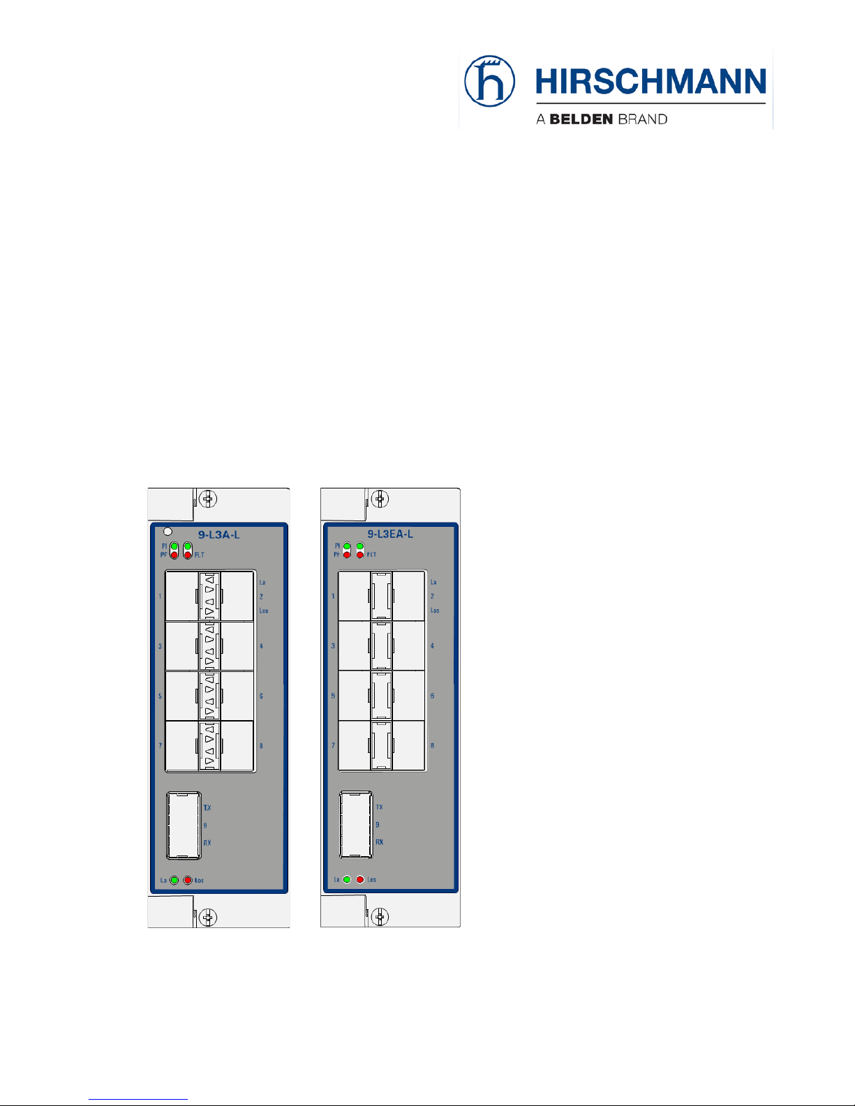
Interface Module PTN-9-L3A-L (Main)
Interface Module PTN-9-L3EA-L (Extension)

The naming of copyrighted trademarks in this manual, even when not specially indicated, should not
be taken to mean that these names may be considered as free in the sense of the trademark and
tradename protection law and hence that they may be freely used by anyone.
© 2018 Hirschmann Automation and Control GmbH
Manuals and software are protected by copyright. All rights reserved. The copying, reproduction,
translation, conversion into any electronic medium or machine scannable form is not permitted,
either in whole or in part. An exception is the preparation of a backup copy of the software for your
own use.
The performance features described here are binding only if they have been expressly agreed when
the contract was made. This document was produced by Hirschmann Automation and Control GmbH
according to the best of the company's knowledge. Hirschmann reserves the right to change the
contents of this document without prior notice. Hirschmann can give no guarantee in respect of the
correctness or accuracy of the information in this document.
Hirschmann can accept no responsibility for damages, resulting from the use of the network
components or the associated operating software. In addition, we refer to the conditions of use
specified in the license contract.
You can get the latest version of this manual on the Internet at the Hirschmann product site
(www.doc.hirschmann.com).
Hirschmann Automation and Control GmbH
Stuttgarter Str. 45-51
72654 Neckartenzlingen
Germany
2 Interface Module PTN-9-L3A-L (Main)/PTN-9-L3EA-L (Extension)
Release 02 11/2018

Contents
1. INTRODUCTION ........................................................................................................... 5
1.1 General ................................................................................................. 5
1.2 Manual References ............................................................................... 6
2. MODULE DESCRIPTION ................................................................................................ 7
2.1 Front Panel ........................................................................................... 7
2.1.1 Insert/Remove Module from Node ........................................................... 7
2.1.2 LEDs ............................................................................................................ 8
2.1.3 Hidden Reset Button (Only on main L3 IFM) ........................................... 10
2.1.4 Connectors ............................................................................................... 10
2.2 Functional Operation .......................................................................... 10
2.2.1 Media Module for Ethernet: Interfacing to a LAN Network ................... 10
2.2.2 I/O with the Central Switching Module (=CSM) ...................................... 12
2.2.3 Ethernet Service ...................................................................................... 12
2.2.4 Voice Service ............................................................................................ 12
2.2.5 Layer2: VLAN handling ............................................................................. 12
2.2.6 Layer2: QoS (=Quality of Service) ............................................................ 13
2.2.7 Layer2: MSTP (=Multiple Spanning Tree) ................................................ 13
2.2.8 Layer2: LAG (=Link Aggregation Group) .................................................. 14
2.2.9 Layer3: VRF (=Virtual Router Forwarding) ............................................... 14
2.2.10 Layer3: VRRP (=Virtual Router Redundancy Protocol) ............................ 15
2.2.11 Layer3: Static Routing .............................................................................. 16
2.2.12 Layer3: OSPF (=Open Shortest Path First) ............................................... 16
2.2.13 VLAN routing (IPv4) / L3VPN ................................................................... 17
2.2.14 Loopback Interface .................................................................................. 17
2.2.15 Storm Control on Ethernet LAN Port ....................................................... 18
2.2.16 Port Mirroring .......................................................................................... 18
2.2.17 BPDU Guard via MSTP ............................................................................. 18
2.2.18 MRP (=Media Redundancy Protocol) Support ........................................ 19
2.2.19 Hardware Edition ..................................................................................... 19
2.2.20 Protocol Scalability Parameters ............................................................... 19
2.3 Onboard Interfaces ............................................................................. 20
2.3.1 Straps ....................................................................................................... 21
2.3.2 Rotary DIP Switches ................................................................................. 21
2.3.3 Fans (Only on Main L3 IFM) ..................................................................... 21
3. MODULE SPECIFICATIONS .......................................................................................... 22
3.1 General Specifications ........................................................................ 22
3.2 Other Specifications ........................................................................... 22
3.3 Ordering Information ......................................................................... 22
4. ABBREVIATIONS ........................................................................................................ 22
Interface Module PTN-9-L3A-L (Main)/PTN-9-L3EA-L (Extension) 3
Release 02 11/2018

List of figures
Figure 1 Front Panels: Main L3 IFM / Extension L3 IFM ................................................................ 7
Figure 2 PLD Version of Extension L3 No Upgrade Needed .......................................................... 9
Figure 3 PLD Version of Extension L3 Upgrade Process .............................................................. 10
Figure 4 General Example: 2 IP Subnets (Virtual Routing)/LAN/WAN ........................................ 11
Figure 5 Detailed Example with 3 IP Subnets: L3VPN ................................................................. 11
Figure 6 MST Example ................................................................................................................. 13
Figure 7 LAG Example .................................................................................................................. 14
Figure 8 Virtual Router Example ................................................................................................. 15
Figure 9 VRRP Example ................................................................................................................ 16
Figure 10 OSPF Example .............................................................................................................. 17
Figure 11 L3VPN Example ............................................................................................................ 17
Figure 12 Port Mirroring Example ............................................................................................... 18
Figure 13 MRP: General Example ................................................................................................ 19
Figure 14 main L3 IFM: Side View ............................................................................................... 20
Figure 15 Main L3 IFM: 3D View with Fans ................................................................................. 20
Figure 16 Extension L3 IFM: Side View ........................................................................................ 21
List of Tables
Table 1 Differences Main L3 IFM <-> Extension L3 IFM ................................................................ 6
Table 2 Manual References ........................................................................................................... 7
Table 3 LED Indications In Boot Operation: Main L3 IFM ............................................................. 8
Table 4 LED Indications In Boot Operation: Extension L3 IFM ...................................................... 8
Table 5 LED Indications in Normal Operation (Main and Extension L3 IFM) ................................ 8
Table 6 Fan Speed: Temperature Dependent ............................................................................. 21
Table 7 Other Specifications ........................................................................................................ 22
4 Interface Module PTN-9-L3A-L (Main)/PTN-9-L3EA-L (Extension)
Release 02 11/2018

1. INTRODUCTION
1.1 General
This document is valid as of Dragon PTN Release 4.0DR.
This document describes the 9-L3A-L (=main) and 9-L3EA-L (=extension) interface modules
which provide Layer2/Layer3 functionality. If you want more front ports than available on
the main module, use the extension module in addition to double the front ports.
In this manual, following terminology is often used for a better readability:
‘main L3 IFM’ = 9-L3A-L IFM;
‘extension L3 IFM’ = 9-L3EA-L IFM;
‘L3 IFM’ could either mean:
‘main L3 IFM’ only = 8+1 front ports;
The ‘main L3 IFM’ combined with an ‘extension L3 IFM’ = 16+2 front ports;
Both IFMs (=interface module) have 9 optical LAN (=Local Area Network) ports on the front
panel: 8*1Gbps SFP ports and 1*10Gbps XFP port. Each individual port can be configured via
HiProvision (=Dragon PTN Management System). 9-L3A-L refers to ‘9 ports – Layer3, Variant
A IFM – LAN’ whereas the ‘E’ in 9-L3EA-L refers to ‘Extension’.
So using the main and extension L3 IFM together in one node, and plugged in in some
specific interface slots, provides a total of 16*1Gbps SFP ports and 2*10Gbps XFP ports.
Both IFMs are a dual slot [n, n+1] IFM which means that it is 2 slots wide. Only the left-hand
side of the IFM in the left-hand slot will be connected to the node backplane.
Depending on the used slot, the L3 IFM can have up to maximum 5 back end ports to the
Central Switching Module (= CSM, see Ref. [4] in Table 2): 1 to 4 (1Gbps) and 1 (10Gbps). The
maximum bandwidth availability is 14 Gbps (=4+10) and can be reached when the main L3
IFM is plugged into IFM slots [S3-S4] of the XT-2209-A node.
The L3 IFM bandwidth availability (and back end ports) on the Dragon PTN backbone
depends on the used node type and the used slots. Verify the 'Dragon PTN Bandwidth
Overview' manual (Ref. [100] in Table 2) to see in which node and IFM slot this IFM can be
used.
NOTE: Using the extension L3 IFM does not double the amount of back end ports.
Interface Module PTN-9-L3A-L (Main)/PTN-9-L3EA-L (Extension) 5
Release 02 11/2018

Table 1 Differences Main L3 IFM <-> Extension L3 IFM
Main L3 IFM
Extension L3 IFM
Usabililty
Can be used in all nodes according
to Ref. [100] in Table 2.
Can be used in the XT-2209-A node in slot S1(S2).
Dependency
Can be used without the the
extension L3 IFM.
Can only be used together with the main L3 IFM, and this
main L3 IFM must be plugged into slot S3(S4) directly next to
the extension L3 IFM.
Hidden Reset Button
Available
Not available, using the reset button on the main L3 IFM also
resets the extension L3 IFM.
LEDs
LED operation according §2.1.1
Normal LED operation is the same as the main L3 IFM. Boot
LED operation is different. Plugging in the extension L3 IFM
just flashes the LEDs for a few seconds. Next, the LEDs will be
dark for approximately 3 minutes, the time needed for the
main L3 IFM to configure its extension L3 IFM.
Back end ports towards
backplane
Available
Not Available. The main and extension L3 IFM together share
the same back end ports (towards the backplane) of the
main L3 IFM.
Fans/Cooling
Yes
No
Main supported features:
Gigabit Ethernet Ports:
8 x SFP (Fiber, optical): 1000BASE-X;
1 x XFP (Fiber, optical): 10GE;
(main L3 IFM) Cooling: on-board local active cooling via 3 fans mounted on heatsink;
Layer2
L2 VLAN handling;
QoS;
MSTP (=Multiple Spanning Tree);
Layer3
VRF (=Virtual Router Forwarding);
VRRP (=Virtual Router Redundancy Protocol);
Static Routing;
OSPF (=Open Shortest Path First);
VLAN routing (IPv4) / L3VPN;
Port Mirroring;
Storm Control;
BPDU Guard via MSTP;
MRP (=Media Redundancy Protocol) Support.
1.2 Manual References
Table 2 is an overview of the manuals referred to in this manual. ‘&’ refers to the language
code, ‘*’ refers to the manual issue. All these manuals can be found in the HiProvision
(=Dragon PTN Management System) Help function.
6 Interface Module PTN-9-L3A-L (Main)/PTN-9-L3EA-L (Extension)
Release 02 11/2018

Table 2 Manual References
Ref.
Number
Title
[1]
DRA-DRM821-&-*
Dragon PTN and HiProvision Operation
[2]
DRA-DRM801-&-*
Dragon PTN Installation and Operation
[3]
DRB-DRM802-&-*
Dragon PTN Aggregation Nodes: PTN2210, PTN2209, PTN2206, PTN1104
[4]
DRB-DRM803-&-*
Dragon PTN Switching Module: PTN-CSM310-A
[5]
DRE-DRM808-&-*
Dragon PTN Interface Module: PTN-1-10G-LW
[6]
DRE-DRM807-&-*
Dragon PTN Interface Module: PTN-4-GC-LW/PTN-4-GCB-LW
[7]
DRF-DRM811-&-*
Dragon PTN TRMs (Transmit Receive Modules: SFP, XFP)
[8]
DRA-DRM810-&-*
Dragon PTN General Specifications
[9]
DRE-DRM817-&-*
Dragon PTN Interface Module: PTN-4-GO-LW
[100]
DRA-DRM828-&-*
Dragon PTN Bandwidth Overview
2. MODULE DESCRIPTION
2.1 Front Panel
Figure 1 Front Panels: Main L3 IFM / Extension L3 IFM
2.1.1 Insert/Remove Module from Node
See ‘Dragon PTN Installation and Operation Manual’ Ref.[2].
Hidden reset
button
1 - La
1 - Los
2 - La
2 - Los
Fas tening
screw
Handl e
Main IFM: 9-L3A-L
Extension I FM: 9-L3EA-L
8 Optical SFP
1 Gbps ports
8 Optical SFP
1 Gbps ports
1 Optical XFP
10 Gbps port
1 Optical XFP
10 Gbps port
Interface Module PTN-9-L3A-L (Main)/PTN-9-L3EA-L (Extension) 7
Release 02 11/2018
 Loading...