

Page 1
Installation PTN-9-L3A-L Technical support
Release 01 02/2018 https://hirschmann-support.belden.com
User Manual
Installation
Dragon PTN Interface Module
PTN-9-L3A-L
Page 2

2 Installation PTN-9-L3A-L
Release 01 02/2018
The naming of copyrighted trademarks in this manual, even when not specially indicated, should not
be taken to mean that these names may be considered as free in the sense of the trademark and
tradename protection law and hence that they may be freely used by anyone.
© 2018 Hirschmann Automation and Control GmbH
Manuals and software are protected by copyright. All rights reserved. The copying, reproduction,
translation, conversion into any electronic medium or machine scannable form is not permitted,
either in whole or in part. An exception is the preparation of a backup copy of the software for your
own use.
The performance features described here are binding only if they have been expressly agreed when
the contract was made. This document was produced by Hirschmann Automation and Control GmbH
according to the best of the company's knowledge. Hirschmann reserves the right to change the
contents of this document without prior notice. Hirschmann can give no guarantee in respect of the
correctness or accuracy of the information in this document.
Hirschmann can accept no responsibility for damages, resulting from the use of the network
components or the associated operating software. In addition, we refer to the conditions of use
specified in the license contract.
You can get the latest version of this manual on the Internet at the Hirschmann product site
(www.hirschmann.com).
Hirschmann Automation and Control GmbH
Stuttgarter Str. 45-51
72654 Neckartenzlingen
Germany
Page 3

Installation PTN-9-L3A-L 3
Release 01 02/2018
Contents
1. INTRODUCTION ......................................................................................................... 5
1.1 General ............................................................................................... 5
1.2 Manual References ............................................................................. 6
2. MODULE DESCRIPTION .............................................................................................. 7
2.1 Front Panel ......................................................................................... 7
2.1.1 Handle ........................................................................................................ 7
2.1.2 LEDs ............................................................................................................ 8
2.1.3 Hidden Reset button .................................................................................. 8
2.1.4 Connectors ................................................................................................. 9
2.2 Functional Operation .......................................................................... 9
2.2.1 Media Module for Ethernet: Interfacing to a LAN Network ..................... 9
2.2.2 I/O with the Central Switching Module (=CSM) ...................................... 10
2.2.3 Ethernet Service ...................................................................................... 10
2.2.4 Layer2: VLAN handling ............................................................................. 11
2.2.5 Layer2: QoS (=Quality of Service) ............................................................ 11
2.2.6 Layer2: MSTP (=Multiple Spanning Tree) ................................................ 11
2.2.7 Layer3: VRF (=Virtual Router Forwarding)............................................... 12
2.2.8 Layer3: VRRP (=Virtual Router Redundancy Protocol) ............................ 13
2.2.9 Layer3: Static Routing .............................................................................. 13
2.2.10 Layer3: OSPF (=Open Shortest Path First) ............................................... 14
2.2.11 VLAN routing (IPv4) / L3VPN ................................................................... 14
2.2.12 Storm Control on Ethernet LAN Port ....................................................... 15
2.2.13 Port Mirroring .......................................................................................... 15
2.2.14 BPDU Guard via MSTP ............................................................................. 15
2.2.15 Protocol Scalability Parameters ............................................................... 16
2.3 Onboard Interfaces ........................................................................... 16
2.3.1 Straps ....................................................................................................... 17
2.3.2 Rotary DIP Switches ................................................................................. 17
2.3.3 Fans .......................................................................................................... 17
3. MODULE SPECIFICATIONS ........................................................................................ 17
3.1 General Specifications ....................................................................... 17
3.2 Other Specifications .......................................................................... 17
3.3 Ordering Information ........................................................................ 17
4. ABBREVIATIONS ...................................................................................................... 18
Page 4

4 Installation PTN-9-L3A-L
Release 01 02/2018
List of figures
Figure 1 Front Panel ...................................................................................................................... 7
Figure 2 General Example: 2 IP Subnets (Virtual Routing)/LAN/WAN .......................................... 9
Figure 3 Detailed Example with 3 IP Subnets: L3VPN ................................................................. 10
Figure 4 MST Example ................................................................................................................. 12
Figure 5 Virtual Router Example ................................................................................................. 12
Figure 6 VRRP Example ................................................................................................................ 13
Figure 7 OSPF Example ................................................................................................................ 14
Figure 8 L3VPN Example .............................................................................................................. 14
Figure 9 Port Mirroring Example ................................................................................................. 15
Figure 10 9-L3A-L: Side View ....................................................................................................... 16
Figure 11 9-L3A-L: 3D View with Fans ......................................................................................... 17
List of Tables
Table 1 Maximum Bandwidth of the 9-L3A-L IFM on the Dragon PTN Backbone ........................ 5
Table 2 Manual References ........................................................................................................... 6
Table 3 LED Indications In Boot Operation ................................................................................... 8
Table 4 LED Indications in Normal Operation ............................................................................... 8
Table 5 Protocol Scalability Parameters ...................................................................................... 16
Table 6 Other Specifications ........................................................................................................ 17
Page 5
Installation PTN-9-L3A-L 5
Release 01 02/2018
1. INTRODUCTION
1.1 General
This document is valid as of Dragon PTN Release 3.0.
This document describes the 9-L3A-L interface module (=IFM) which provides Layer2 and
Layer3 functionality. This IFM has 9 optical LAN (LAN = Local Area Network) ports on the
front panel: 8*1Gbps SFP ports and 1*10Gbps XFP port. Each individual port can be
configured via HiProvision (=Dragon PTN Management System). 9-L3A-L refers to ‘9 ports –
Layer3 – LAN’.
The 9-L3A-L is a dual slot [n, n+1] IFM which means that it is 2 slots wide. Only the left-hand
side of the IFM in the left-hand slot will be connected to the node backplane.
The 9-L3A-L IFM bandwidth availability on the Dragon PTN backbone depends on the used
node type and the used slots. Depending on the used slot, the IFM can have up to maximum
5 back end ports to the CSM: 1 to 4 (1Gbps) and 1 (10Gbps). The maximum bandwidth
availability is 14 Gbps (=4+10) and can be reached when the IFM is plugged into IFM slots
[S3-S4] of the XT-2209-A node. The available bandwidth per slot overview where the 9-L3A-L
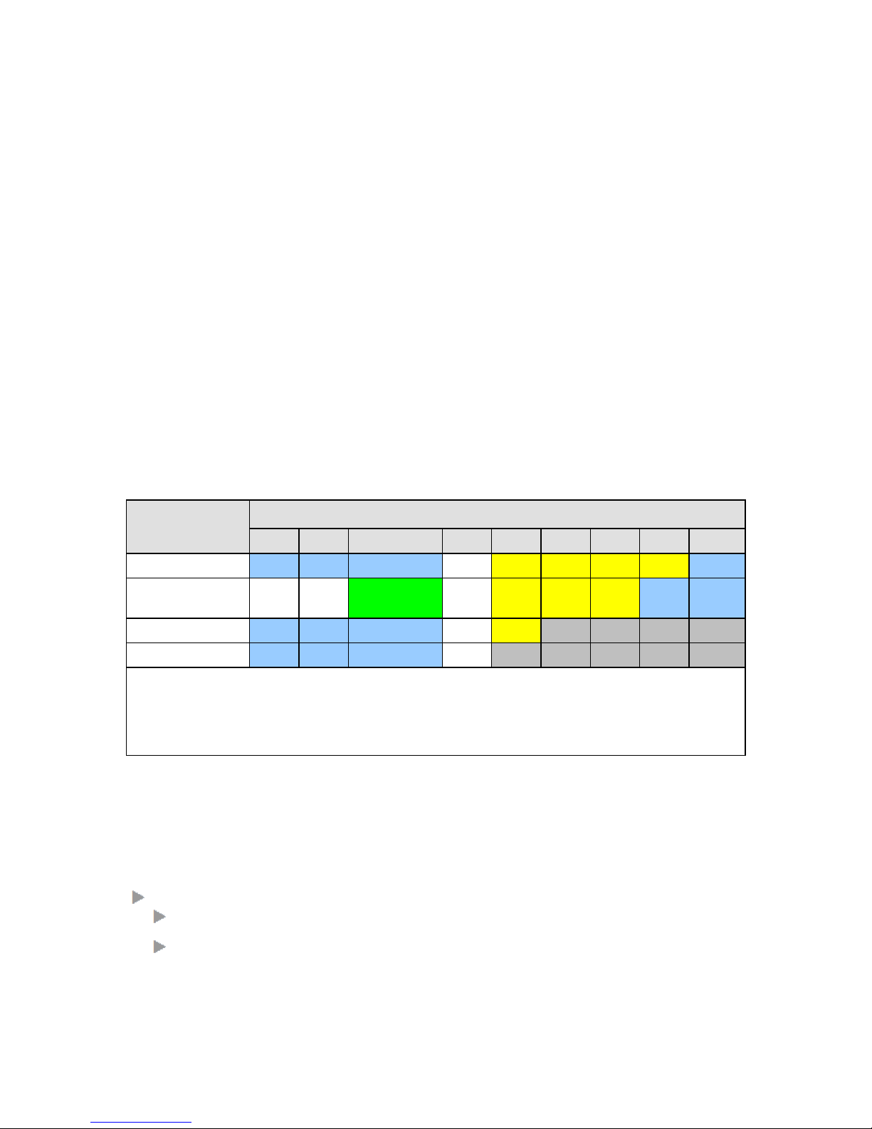
IFM can be used/not used can be found in the table below.
Table 1 Maximum Bandwidth of the 9-L3A-L IFM on the Dragon PTN Backbone
Node Type
Slots
S1(S2)
S2(S3)
S3(S4)
S4(S5)
S5(S6)
S6(S7)
S7(S8)
S8(S9)
S9(S10)
XT-2210-A
4*1G
4*1G
4*1G
---
1*1G
1*1G
1*1G
1*1G
4*1G
XT-2209-A
(optimized for 9-L3A-L)
---(*)
---(*)
4*1G (=BE1-BE4)
1*10G (=BE5)
---
1*1G
1*1G
1*1G
4*1G
4*1G
XT-2206-A
4*1G
4*1G
4*1G
---
1*1G
XT-1104-A
4*1G
4*1G
4*1G
---
Example: The XT-2209-A node has in slot S3-S4, 5 back end ports: 4 * 1Gbps + 1 * 10Gbps
BEn = Back End Port 'n'
--- = 9-L3A-L can not be used in this slot.
(*): These slots have 4*1G bandwidth available but 9-L3A-L cannot be plugged into these slots because of a mechanical
polarisation key next to S1 backplane connector. All other IFMs can be plugged into S1, S2 and S3.
IFM slot overviews for nodes can be found in the Dragon PTN Nodes manual Ref. [3] in
Table 2.
Main supported features:
Gigabit Ethernet Ports:
8 x SFP (Fiber, optical): 1000BASE-X;
1 x XFP (Fiber, optical): 10GE;
Page 6

6 Installation PTN-9-L3A-L
Release 01 02/2018
Cooling: on-board local active cooling via 3 small fans mounted on heatsink;
Layer2
L2 VLAN handling;
QoS;
MSTP (=Multiple Spanning Tree);
Layer3
VRF (=Virtual Router Forwarding);
VRRP (=Virtual Router Redundancy Protocol);
Static Routing;
OSPF (=Open Shortest Path First);
VLAN routing (IPv4) / L3VPN;
Port Mirroring;
Storm Control;
BPDU Guard via MSTP;
1.2 Manual References
Table 2 is an overview of the manuals referred to in this manual. ‘&’ refers to the language
code, ‘*’ refers to the manual issue. All these manuals can be found in the HiProvision
(=Dragon PTN Management System) Help function.
Table 2 Manual References
Ref.
Number
Title
[1]
DRA-DRM821-&-*
Dragon PTN and HiProvision Operation
[2]
DRA-DRM801-&-*
Dragon PTN Installation and Operation
[3]
DRB-DRM802-&-*
Dragon PTN Nodes: PTN2210, PTN2209, PTN2206, PTN1104
[4]
DRB-DRM803-&-*
Dragon PTN Switching Module: PTN-CSM310-A
[5]
DRE-DRM808-&-*
Dragon PTN Interface Module: PTN-1-10G-LW
[6]
DRE-DRM807-&-*
Dragon PTN Interface Module: PTN-4-GC-LW/PTN-4-GCB-LW
[7]
DRF-DRM811-&-*
Dragon PTN TRMs (Transmit Receive Modules: SFP, XFP)
[8]
DRA-DRM810-&-*
Dragon PTN General Specifications
[9]
DRE-DRM817-&-*
Dragon PTN Interface Module: PTN-4-GO-LW
Page 7

Installation PTN-9-L3A-L 7
Release 01 02/2018
2. MODULE DESCRIPTION
2.1 Front Panel
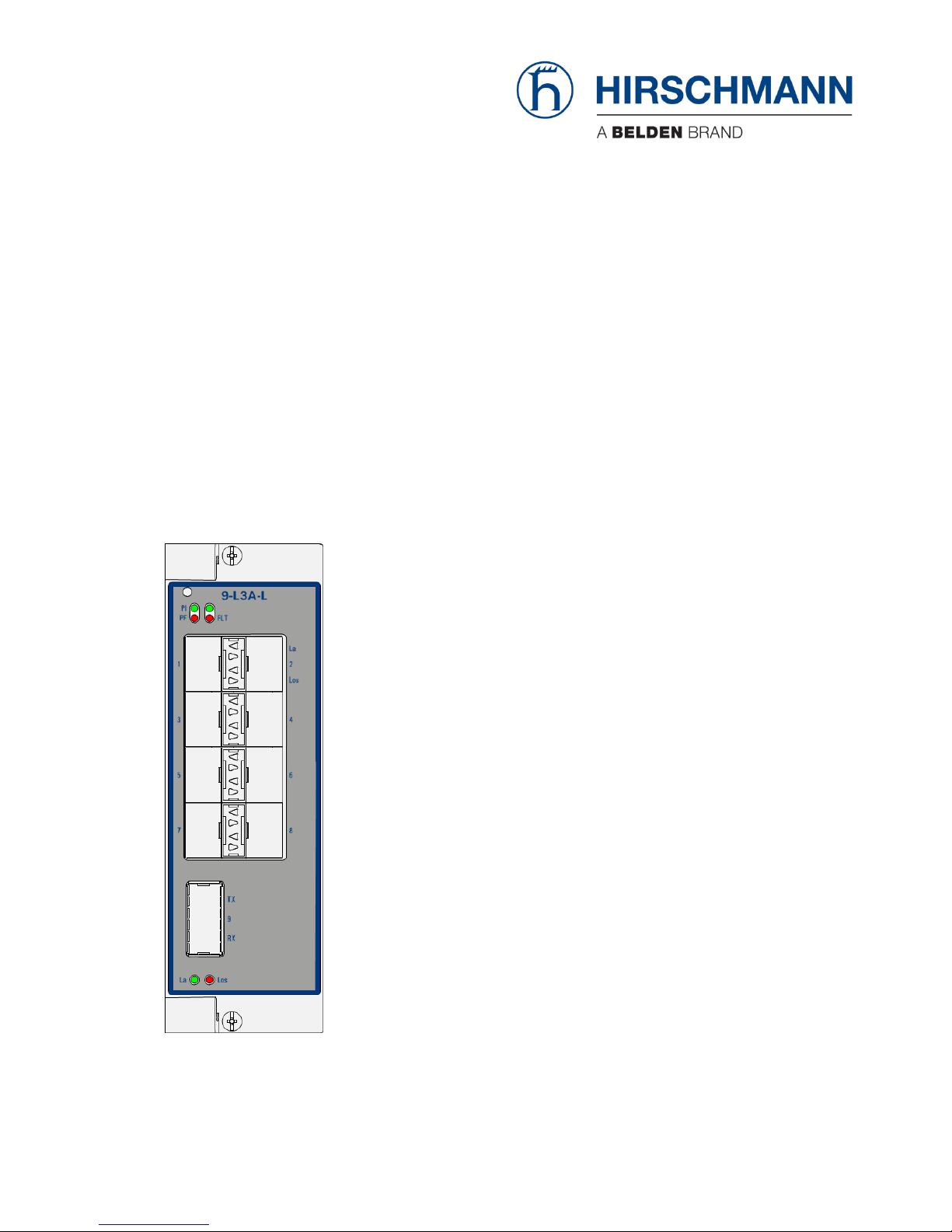
Figure 1 Front Panel
2.1.1 Handle
a. Insert the Module into the Node
Take the front panel handles to insert or slide the module into the Dragon PTN node. Push
the module thoroughly into the node’s backplane. Next, tighten the two fastening screws in
the front panel.
b. Remove the Module from the Node
Untighten the two fastening screws in the front panel. Take the front panel handles to pull
out and finally remove the module from the Dragon PTN node.
1 Optical XFP
10 Gbps port
8 Optical SFP
1 Gbps ports
Hidden Reset button
1 - La
1 - Los
2 - La
2 - Los
Fastening screwHandle
Page 8

8 Installation PTN-9-L3A-L
Release 01 02/2018
2.1.2 LEDs
The meaning of the LEDs depends on the mode of operation (= boot or normal) in which the
9-L3A-L module currently is running. After plugging in the module or rebooting it, the
module turns into the boot operation, see Table 3. After the module has gone through all
the cycles in the table below (=rebooted successfully), the module turns into the normal
operation, see LEDs in Table 4.
Table 3 LED Indications In Boot Operation
Cycle
PI
PF
FLT
Spare LED
La[1..9]
Los[1..9]
1
x
---
Slow blinking
---
---
---
2
x
--- x x
---
---
3
x
---
---
---
---
---
x : LED is lit / --- : LED is not lit. The sub cycle times may vary. The entire boot cycle time [13] takes less than 1
minute.
Table 4 LED Indications in Normal Operation
LED
Color
Status
PI (=Power Input)
Not lit, dark
+12V power input to the board not OK
Green
+12V power input to the board OK
PF (=Power Failure)
Not lit, dark
power generation on the board itself is OK
Red
power generation on the board itself is erroneous
FLT (=FauLT)
Not lit, dark
no other fault or error situation, different from PF, is active on the module
Red
a fault or error situation, different from PF, is active on the module
LA<port n°>
(=Link Activity)
1G Port (Port 1..8)
Not lit, dark
The link on port<port n°> is down
Yellow lit
The link on port<port n°> is up, no activity
Yellow blinking
The link on port<port n°> is up, with activity
10G Port (Port 9)
Not lit, dark
The link on the 10G port is down
Yellow lit
The link on the 10G port is up, no receive activity (transmit activity is not shown)
Yellow blinking
The link on the 10G port is up, with receive activity (transmit activity is not
shown)
LOS<port n°>
(=Loss of Signal)
Not lit, dark
No optical module present or optical module present and received optical signal
= ok
Red
Loss of optical signal on the port
2.1.3 Hidden Reset button
This pushbutton is hidden and accessible through a small hole on the front panel. This
button can be pushed with a sharp fine object e.g. a needle, toothpick… Pushing this reset
button causes a soft reset i.e. it is not a cold reset (power-off-on-cycle).
Page 9

Installation PTN-9-L3A-L 9
Release 01 02/2018
2.1.4 Connectors
This module has following ports:
SFP: 100/1000 Mbps Ethernet optical fiber port / Smart SFP;
XFP: 10 Gigabit Ethernet optical fiber port.
The SFPs/XFPs that can be used for this port can be found in Ref. [7] in Table 2;
2.2 Functional Operation
The 9-L3A-L performs following major tasks:
2.2.1 Media Module for Ethernet: Interfacing to a LAN Network
WAN ports interconnect nodes within the Dragon PTN network (MPLS-TP) whereas LAN
ports interconnect the nodes with their applications. The 9-L3A-L IFM has LAN ports and as a
result can not be used to interconnect nodes. Interconnecting nodes on the WAN side must
be done via LAN/WAN Ethernet IFMs (4-GC-LW, ...).
A LAN port talks Ethernet and a WAN port talks MPLS-TP. As a result, the node can serve as
an edge node (or LER = Label Edge Router) where traffic is received on a LAN port, mapped
into pseudowire and forwarded to the correct label switched path on a WAN port.
For a configured application service, the node can operate as a:
LER = Label Edge Router or access node: The node is located on the edge between the
LAN and WAN. The node converts Ethernet into MPLS-TP and vice versa;
LSR = Label Switching Router: The node is fully located in the WAN. The node has no end-
points for the configured application service, it only forwards MPLS-TP traffic via label
switched paths;
VRF (=Virtural Router forwarding): When an optional Virtual Router has been configured
on the 9-L3A-L IFM, the node operates as a router between different IP subnets.
Figure 2 General Example: 2 IP Subnets (Virtual Routing)/LAN/WAN
LER
LAN WAN LAN
Dragon PTN
MPLS-TP Network
LSR
LSR
LSR
LAN
LER
IP Subnet1
9-L3A-L
with VRF
Dragon PTN
Node
IP Subnet1
192.168.10.x
IP Subnet2
192.168.20.x
HiProvision PC
(=Dragon PTN Management)
Page 10

10 Installation PTN-9-L3A-L
Release 01 02/2018
In the figure below:
FP = 9-L3A-L front port;
BE = 9-L3A-L back end port to the CSM, the amount depends on the node type and slot;
VID = VLAN ID, VFI = Virtual Forwarding Interface.
Figure 3 Detailed Example with 3 IP Subnets: L3VPN
2.2.2 I/O with the Central Switching Module (=CSM)
The 9-L3A-L module receives Ethernet traffic via its front panel ports and forwards this to the
CSM via the back end ports the CSM. The CSM does all the processing on this data
(synchronization, CRC checks, conversions, switching…). The resulting data will be
forwarded via the backplane to one of the IFMs in the node.
2.2.3 Ethernet Service
a. General
The 9-L3A-L IFM access or end-points communicate over the Dragon PTN network via an
Ethernet service. This service must be configured via HiProvision. This service can operate
port or VLAN based.
b. Port Based / VLAN Based
Port based: Use this mode if all the traffic on a port must be transported transparently in
one and the same service;
Node 10
9-L3A-L
Dragon
PTN
FP
BE
4
5
6
7
8
2
3
4
5
1
2
3
4
5
1
2
3
4
5
1
2
3
4
5
3
4
5
6
7
8
9
FPBE
Node 10
CSM
Node 11
CSM
Node 11
9-L3A-L
3
1
2
IP Subnet1
192.168.10.x
IP Subnet2
MPLS-TP Service
(VID 20)
IP Subnet1
Local Service
(VID 10)
20
VFI 20
10
2
1
Node 11
4-GC-LW
1
3
4
2
VFI 20
20
Virtual Router
(VRF)
IP Subnet2
192.168.20.x
L3VPN: routed network over Dragon PTN
1
2
3
4
1
2
3
4
IP Subnet3
192.168.30.x
IP Subnet3
Local Service
(VID 30)
20 30
1
Page 11

Installation PTN-9-L3A-L 11
Release 01 02/2018
VLAN based/VLAN ID: Use this mode if each VLAN (ID) on a port must have its own
service. Ethernet packets with the configured VLAN ID will be forwarded in this service,
other VLAN IDs and untagged packets will be dropped. This behavior can be overruled by
a more advanced VLAN processing in the ‘VLAN Tagging/Untagging’ feature in
HiProvision. This feature also supports VLAN translation which replaces VLAN ID ‘x’ into
VLAN ID ‘y’.
c. VLAN Based Local Service
A VLAN Based Local service is a VLAN based service between only LAN front ports on 9-L3A-L
IFMs. Does not use back end ports, tunnels, WAN ports, the Dragon PTN network and as a
result, this service does not consume network bandwidth.
d. Configuration
See Ref. [1] in Table 2 for more configuration information in HiProvision.
2.2.4 Layer2: VLAN handling
Both port based and VLAN based Ethernet services are supported in which VLANs can be
handled (tagging/untagging behavior, Qos, ...). See Ref. [1] in Table 2 for more configuration
information in HiProvision.
2.2.5 Layer2: QoS (=Quality of Service)
Each Ethernet service can be assigned its own quality of service (bandwidth, priority,
burstsize). See Ref. [1] in Table 2 for more configuration information in HiProvision.
2.2.6 Layer2: MSTP (=Multiple Spanning Tree)
MSTP originally defined in IEEE 802.1s and later merged into IEEE 802.1Q-2003, defines an
extension to RSTP to further develop the usefulness of VLANs. This MSTP instance configures
a separate Spanning Tree for all VLANs included in this instance and blocks all but one of the
possible alternate paths within each Spanning Tree.
If there is only one VLAN in the network, single (traditional) STP works appropriately. If the
network contains more than one VLAN, the logical network configured by single STP would
work, but it is possible to make better use of the alternate paths available by using an
alternate spanning tree for different VLANs or groups of VLANs. More than one VLAN can be
assigned to one MST instance. Multiple MST regions can be operational, each having its own
MSTP instances. The IST (MSTP) instance monitors the entire Region, the CST (MSTP)
instance monitors the links between the regions.
MSTP in a port based service is supported network wide whereas MSTP in a VLAN based
service is supported only locally (not over the 9-L3A-L back end ports). CAUTION: using a
VLAN based service with MSTP over the back end ports could cause loops!
MSTP is fully supported on 9-L3A-L IFMs. On 9-L3A-L IFMs, there is always a default MSTP
running even if no MSTP is configured in HiProvision. See Ref. [1] in Table 2 for more
configuration information in HiProvision.
Page 12

12 Installation PTN-9-L3A-L
Release 01 02/2018
Figure 4 MST Example
2.2.7 Layer3: VRF (=Virtual Router Forwarding)
Virtual Router is a router (instance) created by HiProvision within an 9-L3A-L IFM in an
Dragon PTN node. ‘Virtual’ in this context refers to the fact that it is created
programmatically and that multiple routers can be created within the same IFM, with each
Virtual Router having its own independent routing table. Because the Virtual Routers are
independent, the same or overlapping IP addresses can be used without conflicting with
each other. These routing tables initially only have IP addresses/masks of directly connected
networks. Later on, these routing tables will be extended by using Static Routing, OSPF.
Some scalability parameters can be found in §2.2.15. See example figure below. See Ref. [1]
in Table 2 for more configuration information in HiProvision.
Figure 5 Virtual Router Example
10 12
11
15
14
Block port = Avoid loop
L3 ETH L3 ETH
L3 ETH
MSTP2
MSTP1
L3 ETH
MSTP1
Region1
Region2
L3 ETH
No 9-L3A-L IFM,
0 Virtual Routers
VFIVFIVirtual
Forwarding
Instance
CSM
9-L3A-L
Node with 9-L3A-L IFM
including 3 Virtual Router,
VFI
Page 13

Installation PTN-9-L3A-L 13
Release 01 02/2018
2.2.8 Layer3: VRRP (=Virtual Router Redundancy Protocol)
VRRP (=Virtual Router Redundancy Protocol) is a protocol which increases the availability of
the router of a subnet. This redundancy technology is based upon the sharing of a virtual IP
Address amongst all the router interfaces being part of the same VRRP Group. This is
achieved by combining a master and one or more backup router interfaces into one Group.
The actual routing within the Group is done by the master (=active) router interface whereas
the others act as backup. A router interface becomes master after a master election process.
All the router interfaces within a Group use the same unique virtual IP address, e.g
10.10.10.1. The virtual IP address and router interfaces must be in the same subnet. The
virtual IP address will be the default gateway for its associated VLAN e.g. VLAN with VID 150.
The VRRP wizard in HiProvision can create one or more VRRP instances. Each VRRP instance
can be configured between two or more routers. As a result, a Group will always have one or
more backup router interfaces whenever its active router goes down. See Ref. [1] in Table 2
for more configuration information in HiProvision.
Figure 6 VRRP Example
2.2.9 Layer3: Static Routing
The static routing wizard in HiProvision configures or creates static routes (on the virtual
routers) throughout the network. A route is a path from a source towards a destination via
which the message has to travel to reach the destination IP network. There can exist
multiple paths from source to destination, but only one path will be the most efficient one.
Routes (with a same destination) can be favored via a distance parameter. See Ref. [1] in
Table 2 for more configuration information in HiProvision.
Virtual Router1
10.10.10.1 10.10.10.2
VID 150 VID 150
VRRP Master VRRP Backup
Master Backup
Node 80 Node 85
10.10.10.x/24
VID 150
Virtual Router2
Access Node
HiProvision
VRRP
VRRP: Group of routing interfaces
sharing one Virtual IP address to
backup each other:
e.g. 10.10.10.254
Page 14

14 Installation PTN-9-L3A-L
Release 01 02/2018
2.2.10 Layer3: OSPF (=Open Shortest Path First)
OSPF is a dynamic routing protocol for IP networks. A dynamic routing protocol always
determines the best possible routing path. For example, determined routes may dynamically
change because a specific route becomes less or more preferred than before.
The concept of OSPF is that routers advertise updates of their link states to neighboring
routers. And the neighboring router does the same to its neighboring router and so on…. In
other words, each router learns from the other routers based on link state advertisements
(=LSA). OSPF is a fast protocol because only updates are advertised.
OSPF checks the availability of others routers in the network by sending ‘Hello’ packets. If
the other router does not respond then that router is assumed to be down. See Ref. [1] in
Table 2 for more configuration information in HiProvision.
Figure 7 OSPF Example
2.2.11 VLAN routing (IPv4) / L3VPN
A L3VPN (or Layer3 VPN) is a routed network within Dragon PTN that interconnects one or
more IP subnets via the MPLS-TP backbone. One or more Ethernet LAN ports from one IP
subnet will be able to communicate with one or more Ethernet LAN ports in another IP
subnet. The L3VPN is created via configuring an MPLS-TP service and one or more local LAN
serivces interconnecting them via a virtual router on a 9-L3A-L IFM. See Figure 3 for a
detailed example. See Ref. [1] in Table 2 for more configuration information in HiProvision.
Figure 8 L3VPN Example
10
13
11
OSPF
Autonomous System
Area 0.0.0.0
OSPF
ASBR
Internet
ABR
Area 0.0.0.1
OSPF
Dragon PTN
MPLS-TP backbone
L3VPN
IP subnet 1
IP subnet 2
IP subnet 3
Page 15

Installation PTN-9-L3A-L 15
Release 01 02/2018
2.2.12 Storm Control on Ethernet LAN Port
A traffic storm is the growing of excessive network traffic due to Ethernet packets flooding
the LAN. Such a storm can for example occur because of a data loop in the network due to
no or misconfiguration of MSTP. These storms degrade the network performance and must
be avoided whenever possible.
The storm control feature:
is an extra protection against these traffic storms;
can be configured on the IFM ports;
limits the amount of unlearned received data (Unicast, Broadcast, Multicast) on the LAN
port ingress or input side;
limits the amount of transmitted data (all data) on the LAN port egress or output side;
Data that exceeds the configured limitations will be dropped. As a result, a possible data
storm cannot overload the node processor or the node will limit outgoing data.
See Ref. [1] in Table 2 for more configuration information in HiProvision.
2.2.13 Port Mirroring
Port Mirroring is a network debugging or monitoring feature. It is used in the Dragon PTN
node to send a copy of network packets seen on a source port (=mirrored port) to a
destination port (=mirroring port). This feature can be used for network appliances that
require monitoring of network traffic, such as an intrusion-detection system etc... Port
mirroring is supported when source and destination ports are located in the same 9-L3A-L
IFM. See Ref. [1] in Table 2 for more configuration information in HiProvision.
Figure 9 Port Mirroring Example
2.2.14 BPDU Guard via MSTP
BPDU Guard on 9-L3A-L IFMs is supported via the MSTP protocol wizard which can be
configured in HiProvision. BPDU Guard (=Bridge Protocol Data Unit) is a LAN port property or
feature that shuts down the LAN port when a BPDU packet enters this port. As a result, this
feature or IFM:
protects the network against possible loops created via this IFM;
Page 16

16 Installation PTN-9-L3A-L
Release 01 02/2018
protects a running MSTP protocol somewhere else in the Dragon PTN network from
external MSTP influences via this LAN port, e.g. root bridge protection etc....
See Ref. [1] in Table 2 for more configuration information in HiProvision.
2.2.15 Protocol Scalability Parameters
Find below some protocol scalability parameters.
Table 5 Protocol Scalability Parameters
Scalability Parameter
Per VRF in 9-L3A-L IFM
Total per 9-L3A-L IFM
VLAN IDs
4K
VRFs 1 64
L3-VLANs / IP Interfaces
256
256
MAC addresses
16k
ARP entries
2K
4K
Unicast routes
3K
12K
Multicast routes
1K
1K
VRRP instance
64
64
OSPF Neighbors
32
128
ACL L2 and L3
798
2.3 Onboard Interfaces
Figure 10 9-L3A-L: Side View
Fans
Page 17

Installation PTN-9-L3A-L 17
Release 01 02/2018
Figure 11 9-L3A-L: 3D View with Fans
2.3.1 Straps
No straps on the board.
2.3.2 Rotary DIP Switches
No rotary DIP switches on board.
2.3.3 Fans
The three fans are always on and running at the same speed for cooling the 9-L3A-L IFM.
Future support: temperature dependent fan-speed control.
3. MODULE SPECIFICATIONS
3.1 General Specifications
For general specifications like temperature, humidity, EMI... see Ref.[8] in Table 2.
3.2 Other Specifications
Table 6 Other Specifications
Description
Value
Weight
0.629 kg / 1.4 lb
MTBF
80 years at 25°C/77°F
Power Consumption
35.0 W (measured at 25°C/77°F, with data transport and fans running)
Module Size
width: 40.32 mm / 1.6 inches
height: 126 mm / 4.96 inches
depth: 195 mm / 7.68 inches
3.3 Ordering Information
PTN-9-L3A-L: 942 236-005.
Page 18

18 Installation PTN-9-L3A-L
Release 01 02/2018
4. ABBREVIATIONS
BE
Back End Port
BPDU
Bridge Protocol Data Unit
CE
Conformité Européenne
CSM
Central Switching Module
EMI
Electromagnetic Interference
FLT
Fault
FP
Front Port
IEC
International Electrotechnical Commission
IEEE
Institute of Electrical and Electronics Engineers
IETF
Internet Engineering Task Force
IFM
InterFace Module
L3VPN
L3 Virtual Private Network
LAN
Local Area Network
LER
Label Edge Router
LSA
Link State Advertisement
LSR
Label Switching Router
MSTP
Multiple Spanning Tree
MTBF
Mean Time Between Failures
OSPF
Open Shortest Path First
Qos
Quality of Service
PTN
Packet Transport Network
VFI
Virtual Forwarding Interface
VID
VLAN ID
VLAN
Virtual LAN
VRF
Virtual Router Forwarding
VRRP
Virtual Router Redundancy Protocol
WAN
Wide Area Network
 Loading...