

Page 1
User Manual
Installation
Dragon PTN
Interface Module PTN-8-FXS
Interface Module PTN-8-FXS Technical Support
Release 01 02/2018 https://hirschmann-support.belden.com
Page 2

The naming of copyrighted trademarks in this manual, even when not specially indicated, should not
be taken to mean that these names may be considered as free in the sense of the trademark and
tradename protection law and hence that they may be freely used by anyone.
© 2018 Hirschmann Automation and Control GmbH
Manuals and software are protected by copyright. All rights reserved. The copying, reproduction,
translation, conversion into any electronic medium or machine scannable form is not permitted,
either in whole or in part. An exception is the preparation of a backup copy of the software for your
own use.
The performance features described here are binding only if they have been expressly agreed when
the contract was made. This document was produced by Hirschmann Automation and Control GmbH
according to the best of the company's knowledge. Hirschmann reserves the right to change the
contents of this document without prior notice. Hirschmann can give no guarantee in respect of the
correctness or accuracy of the information in this document.
Hirschmann can accept no responsibility for damages, resulting from the use of the network
components or the associated operating software. In addition, we refer to the conditions of use
specified in the license contract.
You can get the latest version of this manual on the Internet at the Hirschmann product site
(
www.doc.hirschmann.com).
Hirschmann Automation and Control GmbH
Stuttgarter Str. 45-51
72654 Neckartenzlingen
Germany
2 Interface Module PTN-8-FXS
Release 01 02/2018
Page 3

Contents
1. INTRODUCTION .............................................................................................................. 5
1.1
General ........................................................................................ 5
1.2
Manual References ...................................................................... 6
2. MODULE DESCRIPTION ...................................................................................................... 7
2.1
Front Panel .................................................................................. 7
2.1.1 Handle ............................................................................................ 7
2.1.2 LEDs .................................................................................................. 8
2.1.3 RJ-45 Connector Connections and Cables ...................................... 9
2.2
Functional Operation ................................................................. 11
2.2.1 General ......................................................................................... 11
2.2.2 I/O with the Central Switching Module (=CSM) ............................ 11
2.2.3 Voice Service: Remote Extension (FXO Gateway) .................................... 11
2.2.4 Voice Service: SIP-Server ............................................................... 12
2.2.5 SIP Connections ............................................................................. 12
2.3
Onboard Interfaces .................................................................... 14
2.3.1 Straps ............................................................................................ 15
2.3.2 DIP Switches ................................................................................... 15
2.3.3 Hardware Edition ........................................................................... 15
3. COMPATIBILITY ............................................................................................................ 15
4. MODULE SPECIFICATIONS
............................................................................................. 15
4.1
General Specifications ............................................................... 15
4.2
Other Specifications .................................................................. 15
4.3
Ordering Information ................................................................ 15
5. ABBREVIATIONS ........................................................................................................... 16
List of figures
Figure 1 Analog Voice Example: Remote Extension ........................................................................ 6
Figure 2 Analog Voice Example: SIP Server ...................................................................................... 6
Figure 3 Front Panel ......................................................................................................................... 7
Figure 4 8-FXS Connection: Unplugged ............................................................................................ 9
Figure 5 8-FXS Connection: Plugged .............................................................................................. 10
Figure 6 8-FXS RJ-45 Connector ..................................................................................................... 10
Figure 7 Detailed Functional 8-FXS Example ................................................................................... 11
Figure 8 Basic SIP Registration Process .......................................................................................... 13
Figure 9 Basic SIP Call Example Setup Between End-Points .......................................................... 14
Figure 10 8-FXS: Side View ............................................................................................................. 14
Interface Module PTN-8-FXS
Release 01 02/2018
3
Page 4

List of Tables
Table 1 Manual References .............................................................................................................. 7
Table 2 LED Indications In Boot Operation ...................................................................................... 8
Table 3 LED Indications In Normal Operation .................................................................................. 8
Table 4 Connection Products ........................................................................................................... 9
Table 5 8-FXS RJ-45 Cable-Coupler: Pin Assignments .................................................................... 10
Table 6 Other Specifications .......................................................................................................... 15
4 Interface Module PTN-8-FXS
Release 01 02/2018
Page 5

1. INTRODUCTION
1.1 General
This document is valid as of Dragon PTN Release 3.0DR.
In general, FXS (=Foreign eXchange Subscriber) and FXO (=Foreign eXchange Office)
gateways translate analog voice/modem/fax signals to IP packets and vice versa.
FXO: towards analog PBX (=Private Branch eXchange) or PSTN;
FXS: towards analog telephones, modems or faxes.
The 8-FXS interface module (=IFM) is a VoIP module and makes the transport of analog voice
through the Dragon PTN packet network possible. It will convert analog voice into SIP
(=Session Initiation Protocol) and RTP messages and vice versa. The SIP messages will be
packetized into MPLS-TP packets via a Voice service in HiProvision, to transport the data
through the Dragon PTN network. HiProvision is the Dragon PTN management system.
The Voice service can set up connections between both analog phones and SIP elements
(client, server, trunk). SIP elements can be connected to the Dragon PTN network via
Ethernet IFMs (e.g. 4-GC-LW, ...). Depending on where the call handling must be done, two
different modes can be selected:
Remote extension (FXO Gateway): call handling via FXO gateway to analog public or
private telephone networks;
SIP-server: call handling done in dedicated external SIP server;
This IFM provides 8 ports for connecting 8 analog phones to the Dragon PTN network. It can
be used in any IFM slot of any node. An IFM slot overview can be found in Ref. [3] in Table 1.
Maximum four Voice services can be configured per 8-FXS module.
The main supported features are:
Packetizing of analog voice;
8 ports FXS (G.712 compliant);
Integrated battery feed and ringing generator;
DTMF Dialing;
Converts analog FXS port into SIP Client;
Support for G.711 a/μ law and G.729
encoding/decoding; Modem and fax compatible (no
T.38);
Remote Extension: FXO interworking possible via external device;
Interworks with standard SIP servers;
Voice service modes:
Remote extension (Routable);
SIP-server (Routable);
NOTE:
Routable: FXO Gateway or SIP Server can be located in an IP subnet different
from the IP subnet assigned to the 8-FXS ports;
Compatible products can be found in §3.
A general analog Voice service example can be found in the next figure:
Interface Module PTN-8-FXS
Release 01 02/2018
5
Page 6

Analog Voice
Ethernet IP
Voice
Module
8-FXS
Dragon
PTN Node
MPLS-TP Dragon PTN Network
WAN
Ethernet
Module
e.g. 4-GC-LW
VoIP
Gateway
(=FXO GW)
Analog Voice
Links
Packetized Voice
Public (PSTN, ISDN, ...)
or
Private (PBX)
Figure 1 Analog Voice Example: Remote Extension
Analog Voice
Ethernet IP
Dragon
PTN Node
Voice
Module
8-FXS
Packetized Voice
MPLS-TP Dragon PTN Network
WAN
Ethernet
Module
e.g. 4-GC-LW
VoIP
Gateway
(=FXO GW)
Analog Voice
Links
Public (PSTN, ISDN, ...)
or
Private (PBX)
SIP
Phone
SIP Server
/ IP PBX
SIP
Trunk
Internet
SIP
Client
Figure 2 Analog Voice Example: SIP Server
1.2 Manual References
Table 1 is an overview of the manuals referred to in this manual. ‘&’ refers to the language
code, ‘*’ refers to the manual issue. All these manuals can be found in the HiProvision
(=Dragon PTN Management System) Help function.
6 Interface Module PTN-8-FXS
Release 01 02/2018
Page 7

Table 1 Manual References
Ref. Number Title
[1] DRA-DRM821-&-* Dragon PTN and HiProvision Operation
[2] DRA-DRM801-&-* Dragon PTN Installation and Operation
[3] DRB-DRM802-&-* Dragon PTN Nodes: PTN2210, PTN2209, PTN2206, PTN1104
[4] DRB-DRM803-&-* Dragon PTN Switching Module: PTN-CSM310-A
[5] DRE-DRM807-&-* Dragon PTN Interface Module: PTN-4-GC-LW / PTN-4-GCB-LW
[6] DRE-DRM808-&-* Dragon PTN Interface Module: PTN-1-10G-LW
[7] DRE-DRM817-&-* Dragon PTN Interface Module: PTN-4-GO-LW
[8] DRA-DRM810-&-* Dragon PTN General Specifications
2. MODULE DESCRIPTION
2.1 Front Panel
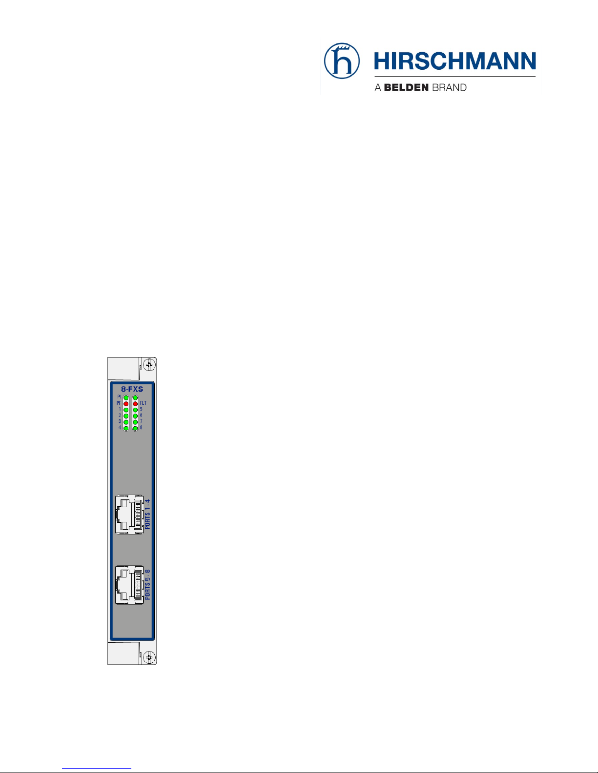
Figure 3 Front Panel
2.1.1 Handle
a. Insert the Module into the Node
Take the front panel handles to insert or slide the module into the Dragon PTN node. Push
the module thoroughly into the node’s backplane. Next, tighten the two fastening screws in
the front panel corners.
Fastening screw
Handle
Spare
LED
LEDs
RJ-45 Connector:
Voice Port [1...4]
RJ-45 Connector:
Voice Port [5...8]
Interface Module PTN-8-FXS
Release 01 02/2018
7
Page 8

b. Remove the Module from the Node
Untighten the two fastening screws in the front panel corners. Take the front panel handles
to pull out and finally remove the module from the Dragon PTN node.
2.1.2 LEDs
The meaning of the LEDs depends on the mode of operation (= boot or normal) in which the
8-FXS module currently is running. After plugging in the module or rebooting it, the module
turns into the boot operation, see Table 2. After the module has gone through all the cycles
in the table below (=rebooted successfully), the module turns into the normal operation, see
LEDs in Table 3.
Table 2 LED Indications In Boot Operation
Cycle PI PF FLT Spare LED Port[1..8]
1 x --- --- --- see Table 3
2 x --- Slow blinking --- see Table 3
3 x --- Fast blinking --- see Table 3
4 x --- --- --- ---
5 x --- --- --- slow blinking
x : LED is lit / --- : LED is not lit
The sub cycle times may vary. The entire boot cycle time [1 5] takes approximately 1 minute.
Table 3 LED Indications In Normal Operation
LED Color Status
PI (=Power Input) Not lit, dark +12V power input to the board not OK
Green +12V power input to the board OK
PF (=Power Failure) Not lit, dark power generation on the board itself is OK
Red power generation on the board itself is erroneous
FLT (=FauLT) Not lit, dark no other fault or error situation, different from PF, is active on the module
Red a fault or error situation, different from PF, is active on the module
Spare Not lit, Green spare
<port n°> Not lit, dark - port configured (*): connected analog phone is on hook and registered (**)
Green, slow blinking
connected analog phone is on hook together with one of the conditions below:
- not configured
- not registered (**)
Green, fast blinking connected analog phone is off hook together with one of the conditions below:
- not configured
- not registered (**)
Green, lit connected analog phone is off hook and registered (**)
(*) Port Configured: a port is configured when it is programmed in a Voice service and it has a created account. The account
must have been created via the Voice Protocol wizard in HiProvision.
(**) Register: The analog phones must have been announced or registered first to a third party FXO gateway or SIP-server. This
occurs via a 'REGISTER' message. After registration, the SIP server or FXO gateway knows via which IP address and extension
number the analog phones can be reached. The REGISTER message will be sent automatically by the port, every 120 seconds,
after the port has been configured and loaded in HiProvision. No phone has to be connected yet to start the registration. See
also §2.2.5 for more info on the Register flow.
8 Interface Module PTN-8-FXS
Release 01 02/2018
Page 9

2 * RJ-45 Drop Cable to 2 * 4 RJ-11 Couplers:
(future support)
24 Ports Patch Panel, Feedthrough:
942 256-204
Analog Telephone
RJ-11 Cable
RJ-45
RJ-11 Inline
Coupler
port 1
port 4
port 5
port 8
2.1.3 RJ-45 Connector Connections and Cables
The 8-FXS module provides 8 analog voice ports via 2 RJ-45 connectors, each connector
providing 4 ports. Each port provides one tip/ring pair. Connections to this IFM can be made
via a connection kit that can be plugged as well in a patch panel:
8-FXS Connection Kit (future support) includes:
An RJ-45 drop cable (1.5m) wired out on 4*RJ-11 couplers to connect ports [1..4];
An RJ-45 drop cable (1.5m) wired out on 4*RJ-11 couplers to connect ports [5..8];
Patch panel (order no. 942 256-204):
24 ports feedthrough patch panel. The RJ-45 drop cables from the connection kit can
be plugged into this patch panel.
Analog telephony RJ11 cables must be plugged into the RJ-11 couplers to connect to
the 8-FXS ports;
See the table and figures below for an overview and description of the different
connections, connectors and pin assignments.
Table 4 Connection Products
Description Ordering Number
8-FXS Connection Kit future support
Patch panel 1 U feedthrough 24 ports (to be used in combo with the 8-FXS Connection Kit 942 256-204
Figure 4 8-FXS Connection: Unplugged
... ...
... ...
Interface Module PTN-8-FXS
Release 01 02/2018
9
Page 10

Figure 5 8-FXS Connection: Plugged
Figure 6 8-FXS RJ-45 Connector
Table 5 8-FXS RJ-45 Cable-Coupler: Pin Assignments
8-FXS RJ45 Connector Cable Coupler
Port
No.
Pin
No.
Descript
ion
Wire
Colors
Coupler
No.
Pin
No.
Color
1 1 TIP1 white/orange 1 2 Green
2 RING1 orange 3 White Blue
2 3 TIP2 white/green 2 2 Green
6 RING2 green 3 White Blue
3 4 TIP3 blue 3 2 Green
5 RING3 white/blue 3 White Blue
4 7 TIP4 white/brown 4 2 Green
8 RING4 brown 3 White Blue
5 1 TIP5 white/orange 5 2 Green
2 RING5 orange 3 White Blue
6 3 TIP6 white/green 6 2 Green
6 RING6 green 3 White Blue
7 4 TIP7 blue 7 2 Green
5 RING7 white/blue 3 White Blue
8 7 TIP8 white/brown 8 2 Green
8 RING8 brown 3 White Blue
1 8
1
4 5 8
... ...
... ...
10 Interface Module PTN-8-FXS
Release 01 02/2018
Page 11

2.2 Functional Operation
2.2.1 General
An application network can be connected to the MPLS-TP Dragon PTN network via one of
the 8 FXS interface ports. The 8-FXS module can interface with 8 analog telephone lines. In
Figure 1 and Figure 2, a common functional setup is shown.
In Figure 7 below, a more detailed functional setup is shown. An application network
interfaces the Dragon PTN node via the FXS ports on the 8-FXS module. The 8-FXS converts
this traffic into Ethernet traffic on the backplane. The Central Switching Module (=CSM310A) converts this Ethernet traffic into packetized MPLS-TP and transmits it via an Ethernet IFM
(e.g. 4-GC-LW) onto the Dragon PTN MPLS-TP network.
LAN: Analog Voice external devices
WAN: MPLS-TP (on fiber, copper) between Dragon PTN nodes
Ethernet
node internal
Ethernet
node internal
Figure 7 Detailed Functional 8-FXS Example
2.2.2 I/O with the Central Switching Module (=CSM)
The 8-FXS module receives analog voice via its front panel ports and converts this into
Ethernet traffic which is forwarded to the CSM via the backplane. The CSM does all the
processing on this data (synchronization, CRC checks, conversions, switching…). The CSM
converts this data into MPLS-TP packets and transmits it via an Ethernet IFM (e.g. 4-GC-LW)
onto the WAN. On the destination side, the same processing occurs in reverse order.
2.2.3 Voice Service: Remote Extension (FXO Gateway)
See Figure 1: connections between FXS VoIP Gateway (=FXO-GW);
Analog phones in the Dragon PTN network are a remote extension of the public (PSTN)
and/or private (PBX) telephone network. The extension is possible via a third party FXOGW (e.g. Patton);
8-FXS
Module
MPLS-TP Dragon PTN Network
WAN
Packetized Voice
4-GC-LW
Module
Dragon PTN Node
WAN
IFM1
8-FXS
IFM2
4-GC-LW
CSM
CSM310-A
Dragon PTN Node
IFM1
8-FXS
IFM2 IFM3 CSM
4
-GC-LW 4-GC-LW
CSM310-A
Analog
Voice
Port
Switch
ETH
MPLS-TP
Switch
ETH
MPLS-TP
Ethernet
Links
LAN
Analog Voice
Links
Analog Voice
Links
VoIP
Gateway
(=FXO GW)
Public (PSTN, ISDN, ...)
or
Private (PBX)
Interface Module PTN-8-FXS
Release 01 02/2018
11
Page 12

Analog phones are connected to an FXS interface (8-FXS module);
FXO Gateways are connected to an Ethernet interface (e.g. 4-GC-LW module);
Voice switching and telephony feature handling between all phones are performed in
the PSTN or PBX;
DTMF (=Dual Tone Multi-Frequency) must be used for number dialing;
Analog speech and signaling are converted and packetized by the FXS interface and the
FXO-GW towards the Dragon PTN network
To set up an entire Voice service in HiProvision (See Ref.[1] in Table 1):
a. Configure a Voice service in HiProvision. A voice service requires at least one 8-FXS port
and one Ethernet port (e.g. 4-GC-LW).
b. Configure a Voice Protocol in the configured Voice service. This voice protocol is
necessary to configure extra/enhanced voice parameters.
NOTE:
8-FXS ports are always consumed per pair in a Voice service: port1+port2;
port3+port4; port5+port6; port7+port8. So if you configure port5 in a first service
e.g. Voice1, port6 can only be used in the same Voice1 service.
2.2.4 Voice Service: SIP-Server
See Figure 2: SIP elements like a SIP Phone and VoIP gateway can be registered on and
handled by the SIP Server;
Analog phones are connected to an FXS interface (8-FXS module) which are registered on
the SIP Server;
Voice switching and telephony feature handling for all calls are performed in the SIP
Server;
Possible SIP telephony features depend on the used SIP devices and their
interoperability.
To set up an entire Voice service in HiProvision (See Ref.[1] in Table 1):
c. Configure a Voice service in HiProvision. A voice service requires at least one 8-FXS port
and one Ethernet port (e.g. 4-GC-LW).
d. Configure a Voice Protocol in the configured Voice service. This voice protocol is
necessary to configure extra/enhanced voice parameters.
NOTE:
8-FXS ports are always consumed per pair in a Voice service: port1+port2;
port3+port4; port5+port6; port7+port8. So if you configure port5 in a first service
e.g. Voice1, port6 can only be used in the same Voice1 service.
2.2.5 SIP Connections
After a Voice service and Voice protocol has been configured in HiProvision, voice calls (or
connections) between analog and/or SIP clients can be set up via SIP calls.
Before any SIP call is possible between end clients A and B, both A and B must register first
to a SIP Server, whatever mode is used, either Remote Extension or SIP Server. A registration
12 Interface Module PTN-8-FXS
Release 01 02/2018
Page 13

attempt from the 8-FXS IFM automatically occurs (every 120 seconds) when the port on
which A or B is or will be connected, is configured in HiProvision. As a result of a successful
registration process, A and B and their location will be known by the SIP server.
Remote Extension mode: The external FXO Gateway device acts as SIP server;
SIP Server mode: A Server PC with SIP Server software can act as SIP server;
Once the registration has been done, a voice call between A and B is possible. Basically,
when A calls B, a SIP Invite message will be sent to the SIP server first, which redirects the
Invite message to B. B starts ringing, picks up the phone and the Voice call has been set up.
Once the voice call has been established, Real-time Transport Protocol (=RTP) is used to
transport the call data.
Remote Extension mode: the RTP stream always goes through the FXO Gateway device;
SIP-Server mode: It can be configured in the SIP Server itself whether the RTP stream
goes through the SIP Server. If for example the calls must be monitored or recorded, the
RTP must go through the SIP server. Find below some example SIP flow examples.
Figure 8 Basic SIP Registration Process
VoIP Gateway
Analog Phone + 8-FXS
Public (PSTN, ISDN)
Private (PBX)
SIP Server / IP PBX
SIP Phone or SIP Client
Register
401 Unauthorized
Register
Only when authorisation
is required
200 OK
Interface Module PTN-8-FXS
Release 01 02/2018
13
Page 14

Figure 9 Basic SIP Call Example Setup Between End-Points
2.3 Onboard Interfaces
Figure 10 8-FXS: Side View
CAUTION: The call setup in the figure above may slightly differ depending on the
selected mode!
Invite
100 Trying
Invite
100 Trying
180 Ringing
180 Ringing
200 OK
200 OK
Acknowledge
Acknowledge
Call, RTP Bye
Bye
200 OK
200 OK
B
Callee
Public (PSTN, ISDN)
Private (PBX)
A
Caller
14 Interface Module PTN-8-FXS
Release 01 02/2018
Page 15

2.3.1 Straps
No user relevant straps.
2.3.2 DIP Switches
No user DIP switches.
2.3.3 Hardware Edition
The hardware edition of the IFM has been factory set and can not be changed. It can be read
out via HiProvision in the Software tile, see Ref. [1] in Table 1.
3. COMPATIBILITY
The 8-FXS IFM is compatible with:
4-GC-LW IFM, 4-GCB-LW IFM, 1-10G-LW IFM, 4-DSL-LW IFM;
FXO Gateway: Patton SmartNode: SN4332/JO/UI (Multiport Analog Voip gateway):
SmartNode Multiport FXO VoIP GW, 32 FXO ports presented on RJ21, 1x Fast Ethernet,
Internal UI Power. NOTE: SN43xx : xx indicates amount of ports. Other similar Patton
devices with more/less ports are supported as well.
It means that 8-FXS and all the products mentioned above can be programmed in the same
Voice service.
4. MODULE SPECIFICATIONS
4.1 General Specifications
For general specifications like temperature, humidity, EMI ... see Ref.[8] in Table 1.
4.2 Other Specifications
Table 6 Other Specifications
Description Value
Weight 0.23 kg / 0.5 lb
MTBF 185 years at 25°C/77°F
Power Consumption Measured at 25°C/77°F, with data transport:
- All phones on-hook: 5.6W
- Extra per phone off-hook: 0.9W
- Ringing state: max. 9W
- All phones off-hook: 12.8W
Module Size
width:
20.32 mm / 0.8 inches
height:
126 mm / 4.96 inches
depth:
195 mm / 7.68 inches
4.3 Ordering Information
PTN-8-FXS: future support;
PTN-8-FXS Connection Kit: future support;
Patch panel 1 U feedthrough 24 ports (to be used in combo with the 8-FXS
Connection Kit): 942 256-204.
Interface Module PTN-8-FXS
Release 01 02/2018
15
Page 16

5. ABBREVIATIONS
CSM
Central Switching Module
DTMF
Dual Tone Multi-Frequency
EMI
Electromagnetic Interference
ETH
Ethernet
FLT
Fault
FXO
Foreign eXchange Office
FXS
Foreign eXchange Subscriber
GW Gateway
IEEE
Institute of Electrical and Electronics Engineers
IFM
InterFace Module
IP
Internet Protocol
ISDN
Integrated Services Digital Network
kbps
Kilobit per Second
LAN
Local Area Network
LOS
Loss Of Signal
Mbps
Megabit per Second
MPLS-TP
MultiProtocol Label Switching – Transport Profile
MTBF
Mean Time Between Failures
PBX
Private Branch Exchange
PF Power Failure
PI
Power Input
PTN
Packet Transport Network
PSTN
Public Switched Telephone Network
RTP
Real-time Transport Protocol
SIP
Session Initiation Protocol
VoIP
Voice over IP
WAN
Wide Area Network
16 Interface Module PTN-8-FXS
Release 01 02/2018
 Loading...