

Page 1
Installation PTN-4-2/4WEM Technical support
Release 01 02/2018 https://hirschmann-support.belden.com
User Manual
Installation
Dragon PTN Interface Module
PTN-4-2/4WEM
Page 2

2 Installation PTN-4-2/4WEM
Release 01 02/2018
The naming of copyrighted trademarks in this manual, even when not specially indicated, should not
be taken to mean that these names may be considered as free in the sense of the trademark and
tradename protection law and hence that they may be freely used by anyone.
© 2018 Hirschmann Automation and Control GmbH
Manuals and software are protected by copyright. All rights reserved. The copying, reproduction,
translation, conversion into any electronic medium or machine scannable form is not permitted,
either in whole or in part. An exception is the preparation of a backup copy of the software for your
own use.
The performance features described here are binding only if they have been expressly agreed when
the contract was made. This document was produced by Hirschmann Automation and Control GmbH
according to the best of the company's knowledge. Hirschmann reserves the right to change the
contents of this document without prior notice. Hirschmann can give no guarantee in respect of the
correctness or accuracy of the information in this document.
Hirschmann can accept no responsibility for damages, resulting from the use of the network
components or the associated operating software. In addition, we refer to the conditions of use
specified in the license contract.
You can get the latest version of this manual on the Internet at the Hirschmann product site
(www.hirschmann.com).
Hirschmann Automation and Control GmbH
Stuttgarter Str. 45-51
72654 Neckartenzlingen
Germany
Page 3

Installation PTN-4-2/4WEM 3
Release 01 02/2018
Contents
1. INTRODUCTION ......................................................................................................... 5
1.1 General ............................................................................................... 5
1.2 Manual References ............................................................................. 6
2. MODULE DESCRIPTION .............................................................................................. 6
2.1 Front Panel ......................................................................................... 6
2.1.1 Handle ........................................................................................................ 7
2.1.2 LEDs ............................................................................................................ 7
2.1.3 Voice RJ-45 Ports and Cables ..................................................................... 8
2.2 Functional Operation .......................................................................... 8
2.2.1 General ...................................................................................................... 8
2.2.2 Services ...................................................................................................... 9
2.2.3 CES: CESoPSN (Point-to-Point)................................................................... 9
2.2.4 CES: Hitless Switching .............................................................................. 10
2.2.5 CES: Single Path ....................................................................................... 11
2.2.6 CES: Delay Comparison in CES Features .................................................. 12
2.2.7 I/O with the Central Switching Module (=CSM) ...................................... 12
2.2.8 Synchronization / Clock Distribution / Network Timing .......................... 12
2.2.9 Selftest: Tone Generation/Level Metering .............................................. 14
2.3 Onboard Interfaces ........................................................................... 15
2.3.1 Straps ....................................................................................................... 15
2.3.2 DIP Switches ............................................................................................ 15
3. TDM FRAMES/PACKET FOR CES ................................................................................ 16
3.1 General ............................................................................................. 16
3.2 Bandwidth ........................................................................................ 16
3.3 Delay ................................................................................................ 16
3.3.1 General .................................................................................................... 16
3.3.2 Delay Parameters .................................................................................... 17
3.3.3 Estimated Delay Calculation and Formulas ............................................. 17
3.3.4 Estimated Delay Examples ....................................................................... 18
3.4 Tuning CES = Tuning TDM Frames/Packet .......................................... 18
4. MODULE SPECIFICATIONS ........................................................................................ 19
4.1 General Specifications ....................................................................... 19
4.2 Other Specifications .......................................................................... 19
4.3 Ordering Information ........................................................................ 19
5. ABBREVIATIONS ...................................................................................................... 19
Page 4

4 Installation PTN-4-2/4WEM
Release 01 02/2018
List of figures
Figure 1 General 4Wire Voice Example ......................................................................................... 5
Figure 2 Front Panel ...................................................................................................................... 6
Figure 3 Voice RJ-45 Connector ..................................................................................................... 8
Figure 4 Detailed Function Voice Example .................................................................................... 9
Figure 5 Hitless Switching ............................................................................................................ 11
Figure 6 Single Path Enabled ....................................................................................................... 11
Figure 7 Single Path Disabled ...................................................................................................... 12
Figure 8 4-2W4WEM Clocking/Synchronization Overview ......................................................... 13
Figure 9 4-2/4WEM: Side View.................................................................................................... 15
Figure 10 Hardware Edition ......................................................................................................... 15
Figure 11 CESoPSN Bandwidth .................................................................................................... 16
Figure 12 Delays .......................................................................................................................... 17
List of Tables
Table 1 Manual References ........................................................................................................... 6
Table 2 LED Indications In Boot Operation ................................................................................... 7
Table 3 LED Indications In Normal Operation ............................................................................... 7
Table 4 Voice RJ-45 Connector: Pin Assignments ......................................................................... 8
Table 5 Difference Between Protection and Hitless Switching ................................................... 10
Table 6 Delay Comparison in CES (Features) ............................................................................... 12
Table 7 Clocking Parameters on Port & Service Level ................................................................. 14
Table 8 Estimated Delay Formulas .............................................................................................. 18
Table 9 Estimated Delay (µs) Examples ....................................................................................... 18
Table 10 Other Specifications ...................................................................................................... 19
Page 5

Installation PTN-4-2/4WEM 5
Release 01 02/2018
1. INTRODUCTION
1.1 General
This document is valid as of Dragon PTN Release 3.0DR.
This document describes the 4-2/4WEM interface module (=IFM) which can be used to
interconnect leased line modems, PABXs... via the Dragon PTN Network. This module
provides 4 RJ45 ports to transport analogue voice signals between 300 - 3400Hz with a
maximum level of 5dBm. These ports are balanced voice ports with an impedance of 600Ω.
The used transportation mode is point-to-point 4-Wire voice (2-Wire = future support).
Besides the analogue voice interface, each port also provides an E&M interface (=future
support). E&M (=Ear and Mouth) is a signaling mechanism between telephone switches.
This IFM can be used in any IFM slot of any node. An IFM slot overview can be found in Ref.
[3] in Table 1.
This IFM converts the analogue voice from a voice link into MPLS-TP packets over the Dragon
PTN network, and vice versa. The destination IFM must also compensate for possible jitter
and network delays to keep everything synchronized. A packetized TDM service is called a
Circuit Emulation Service (=CES). A maximum of 4 CESs (1 per port) can be configured per 42/4WEM IFM.
The main supported features are:
Packetizing of analogue voice;
Balanced voice ports, 600Ω impedance; Sample rate 8Khz;
Services
CESoPSN (=CES over Packet Switched Network) 2W/4W Voice;
Hitless Switching / Single Path ;
A general 4Wire Voice example can be found in the figure below:
Figure 1 General 4Wire Voice Example
MPLS-TP Dragon PTN Network
WAN (via SFP on fiber)
4-2/4WEM
Module
Dragon PTN
Node
LAN1
Packetized Voice via
CESoPSN
Voice
Links
Voice
Links
LAN2
Leased Line
Modem
PABX
Page 6
6 Installation PTN-4-2/4WEM
Release 01 02/2018
1.2 Manual References
Table 1 is an overview of the manuals referred to in this manual. ‘&’ refers to the language
code, ‘*’ refers to the manual issue. All these manuals can be found in the HiProvision
(=Dragon PTN Management System) Help function.
Table 1 Manual References
Ref.
Number
Title
[1]
DRA-DRM821-&-*
Dragon PTN and HiProvision Operation
[2]
DRA-DRM801-&-*
Dragon PTN Installation and Operation
[3]
DRB-DRM802-&-*
Dragon PTN Nodes: PTN2210, PTN2209, PTN2206, PTN1104
[4]
DRB-DRM803-&-*
Dragon PTN Switching Module: PTN-CSM310-A
[5]
DRA-DRM810-&-*
Dragon PTN General Specifications
2. MODULE DESCRIPTION
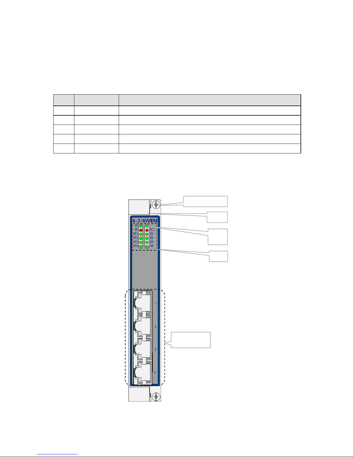
2.1 Front Panel
Figure 2 Front Panel
LEDs
Port 1, 2, 3, 4:
2/4WEM ports
Handle
Spare
LED
Fastening screw
Page 7

Installation PTN-4-2/4WEM 7
Release 01 02/2018
2.1.1 Handle
a. Insert the Module into the Node
Take the front panel handles to insert or slide the module into the Dragon PTN node. Push
the module thoroughly into the node’s backplane. Next, tighten the two fastening screws in
the front panel corners.
b. Remove the Module from the Node
Untighten the two fastening screws in the front panel corners. Take the front panel handles
to pull out and finally remove the module from the Dragon PTN node.
2.1.2 LEDs
The meaning of the LEDs depends on the mode of operation (= boot or normal) in which the
IFM currently is running. After plugging in or rebooting the IFM, the IFM turns into the boot
operation, see Table 2. After the module has gone through all the cycles in the table below
(=rebooted successfully), it will turn into the normal operation, see LEDs in Table 3.
Table 2 LED Indications In Boot Operation
Cycle
PI
PF
FLT
VF[1..4]
S[1..4]
1
x
---
Slow blinking
---
---
2
x
---
Fast blinking
---
---
3
x
---
---
---
---
4
x
---
x
x
x
x : LED is lit / --- : LED is not lit; The sub cycle times may vary. The entire boot cycle time [1→4] takes approximately 2
minutes.
Table 3 LED Indications In Normal Operation
LED
Color
Status
PI (=Power Input)
Not lit, dark
+12V power input to the board not OK
Green
+12V power input to the board OK
PF (=Power Failure)
Not lit, dark
power generation on the board itself is OK
Red
power generation on the board itself is erroneous
FLT (=FauLT)
Not lit, dark
no other fault or error situation, different from PF, is active on the module
Red
a fault or error situation, different from PF, is active on the module
VF<n>
(=Voice Frequency)
Not lit, dark
No service programmed on port<n>
Lit, Green
Programmed service is operational on port<n>
Blinking, Green
Service programmed but no data received on backplane (=network) side
S<n> (=future)
(=E&M Signaling)
Not lit, dark
E wire (from E&M) on the front side (LAN) is not active
Lit, Green
E wire (from E&M) on the front side (LAN) is active
Page 8

8 Installation PTN-4-2/4WEM
Release 01 02/2018
2.1.3 Voice RJ-45 Ports and Cables
The 4-2/4WEM module provides four of these ports and each port connector has eight pins.
See the table and figure below for an overview and description.
4 Wire mode: the signals are transmitted over the transmit pair (TxA-TxB) and received
from the receive pair (RxA-RxB);
2 Wire mode (=future): the signals are transmitted and received over the receive pair
(RxA-RxB);
CAT5E shielded cables must be used to connect the RJ-45 ports;
Figure 3 Voice RJ-45 Connector
Table 4 Voice RJ-45 Connector: Pin Assignments
Pin Number
Description
Input/Output
1 (=future)
E (Ear)
Input
2 (=future)
M (Mouth)
Output
3
TxA (Transmit A)
Output
4
RxA (Receive A)
Input
5
RxB (Receive B)
Input
6
TxB (Transmit B)
Output
7 (=future)
SG (Signal Ground)
---
8 (=future)
SB (Signal Battery)
---
2.2 Functional Operation
2.2.1 General
An application network (e.g. LAN1) can be connected to the MPLS-TP Dragon PTN network
via one of the 4 voice interface ports. The 4-2/4WEM module can interface with 4 voice
lines. In Figure 1, a common functional setup is shown.
In Figure 4 below, a more detailed functional setup is shown. A LAN1 network interfaces the
Dragon PTN node via the voice ports on the 4-2/4WEM module. The 4-2/4WEM converts
this traffic into Ethernet traffic on the backplane. The Central Switching Module (=CSM310A) converts this Ethernet traffic into packetized Voice MPLS-TP and transmits it via an
Ethernet IFM (e.g. 4-GC-LW) onto the Dragon PTN MPLS-TP network. The packetizing of the
voice input occurs via CES: CESoPSN (see §2.2.3) technique.
1 8
Page 9

Installation PTN-4-2/4WEM 9
Release 01 02/2018
Figure 4 Detailed Function Voice Example
2.2.2 Services
A point-to-point '2W/4W Voice' service can be configured in HiProvision via creating a Circuit
Emulation Service (=CES) with protocol type ‘2W/4W Voice’. The incoming analogue signal
will be sampled at a rate of 8 kHz. The digitized voice data will be encapsulated in TDM
packets which will be sent over the Dragon PTN network as Ethernet packets. Following
parameters are needed per service:
CES: Service Type: Circuit Emulation;
Protocol: 2W/4W Voice;
Usage is always CESoPSN;
optional: Hitless Switching;
optional: Single Path;
2.2.3 CES: CESoPSN (Point-to-Point)
CESoPSN (=Circuit Emulation Service over Packet Switched Network)
CESoPSN is a point-to-point service between two voice ports that uses the timeslots of an E1
frame to transport the data over the MPLS-TP Dragon PTN network. One such service can be
configured per port. This service transports the voice data into the first timeslot and the
E&M signaling (=future) in the second timeslot of an E1 frame.
The destination module will receive the transported timeslots from the Dragon PTN network
and regenerate the voice data and the E&M signaling (=future) from it to finally output it on
its voice port.
Each end-point or port must be located in a different node.
CSM
CSM310-A
IFM1
4-2/4WEM
IFM2
4-GC-LW
Switch
ETH
MPLS-TP
Dragon PTN Node
LAN
WAN
4-2/4WEM
CSM
CSM310-A
IFM1
4-2/4WEM
IFM2
4-GC-LW
Switch
ETH
MPLS-TP
Dragon PTN Node
WAN: MPLS-TP (on fiber, copper) between Dragon PTN nodes
Ethernet node internal
LAN: Voice link (on copper) external devices
Voice
Links
Packetized Voice via
CESoPSN
MPLS-TP Dragon PTN Network
WAN (via SFP on fiber)
LAN1
PABX
Voice
Port
Voice
Links
LAN2
Leased Line
Modem
Page 10

10 Installation PTN-4-2/4WEM
Release 01 02/2018
2.2.4 CES: Hitless Switching
Hitless Switching is a feature within CESoPSN that provides a safe redundant connection
where no data or synchronization is lost when switching from the active to the backup path
or vice versa, e.g. because of cable break. The total delay over the network remains nearly
constant during switch-over. Redundancy via Hitless Switching is obtained via completing the
list below:
creating two independent point-to-point tunnels without protection;
setting the Hitless Switching on at service creation time in HiProvision.
NOTE: See Ref.[1] for the creation of tunnels and services;
On the source side, with Hitless Switching enabled, the IFM duplicates each packet on a
second tunnel (e.g. Tunnel y, see figure below). Each packet also contains a 16 bit sequence
number. Different tunnels mean different paths through the network, with each path its
own delay. Different delays result in a slow and a fast path.
On the destination side, with Hitless Switching enabled, the IFM buffers the fastest path and
forwards packets from the slowest path on the voice link. Packets will be processed
according a packet sequence number.
Hitless Switching is a redundant mechanism but differs from Protection Switching, see the
table below for an overview. So if redundancy is needed in the service, either choose Hitless
Switching or Protection Switching, mixing up both mechanisms is not allowed. Depending on
the choice, settings must be done at tunnel creation time and/or service creation time.
When Hitless Switching has been enabled, the CES can only start up with two links up,
coming out of a two-links-down situation (except when Single Path has been enabled, see
§2.2.5).
See §2.2.6 for a delay comparison within CES depending on the enabled sub features, see
also further on.
Table 5 Difference Between Protection and Hitless Switching
Protection Switching
Hitless Switching
required tunnel type
1 point-to-point tunnel
2 point-to-point tunnels
tunnel protection type
1:1;
none; the redundancy is created via two
independent point-to-point tunnels.
service parameter
Hitless Switching = disabled
Hitless Switching = enabled
at switch-over
possible data loss
no data or synchronization loss
total delay
less than hitless switching
more than protection switching
Page 11

Installation PTN-4-2/4WEM 11
Release 01 02/2018
Figure 5 Hitless Switching
2.2.5 CES: Single Path
The Single Path feature is a sub feature of Hitless Switching (see §2.2.4). It influences the
start-up behavior of the Hitless Switching mechanism:
enabled: The CES can already start up with only one link up, coming out of a two-links-
down situation; this setting results in bigger delays because of bigger buffers.
if the fastest path came up first:
the CES starts up according to the fastest path;
possible CES interrupt or minor packet loss when the slowest path comes up
later on;
if the slowest path came up first:
the CES starts up according to the slowest path;
no CES interrupt or packet loss when the fastest path comes up later on;
See §2.2.6 for a delay comparison within CES depending on the enabled sub features, see
also further on.
Figure 6 Single Path Enabled
Voice Data
data
Voice Data
data
Voice WAN:
duplicates and transmits
data twice
WAN Voice:
data buffering = constant de lay;
no packet loss at switch-over
MPLS-TP Dragon PTN
Tunnel x has more nodes
= slow path
Tunnel y has less nodes
= fast path
data data
Single Path ENABLED:
ONE link required
no links up:
no CES
already with one link up
CES starts
Voice data Voice data
MPLS-TP Dragon PTN
MPLS-TP Dragon PTN
Page 12

12 Installation PTN-4-2/4WEM
Release 01 02/2018
Figure 7 Single Path Disabled
2.2.6 CES: Delay Comparison in CES Features
Table 6 Delay Comparison in CES (Features)
CES
Hitless Switching
Single Path
Resulting Delay
X
---
---
lowest
X X ---
medium
X X X
highest
X = enabled; --- = disabled
2.2.7 I/O with the Central Switching Module (=CSM)
The 4-2/4WEM module receives traffic via its front panel ports and converts this into
Ethernet traffic which is forwarded to the CSM via the backplane. The CSM does all the
processing on this data (synchronization, CRC checks, conversions, switching…). The CSM
converts this data into MPLS-TP packets and transmits it via a WAN port (on an IFM that
supports WAN) onto the WAN. On the destination side, the same processing occurs in
reverse order.
2.2.8 Synchronization / Clock Distribution / Network Timing
CAUTION: Make sure to configure/verify the clocking parameters below.
The Dragon PTN network provides a number of mechanisms to perform synchronization /
clock distribution / network timing per CES. The CSM synchronizes all the included IFMs in
the node.
The application endpoints in a 'Circuit Emulation: 2W4W Voice' service can communicate in
a synchronized way. Which method can be used depends on:
data
Voice data
data
Single Path DISABLED:
BOTH links required
only with both links up
CES starts
no links up:
no CES
Voice data
MPLS-TP Dragon PTN
MPLS-TP Dragon PTN
Page 13

Installation PTN-4-2/4WEM 13
Release 01 02/2018
The ‘Clock Source’ setting of port1, this setting will be taken as common setting for the
entire IFM. ‘Clock Source’ settings of port2, 3 and 4 in HiProvision will be ignored;
SyncE availability in the endpoint nodes;
The figures below show relevant end-to-end clocking configurations for this IFM. The PRC
(=Primary Reference Clock) is a very stable high quality clock that can be used as a reference
clock delivered via SyncE to the node:
A, D = Application ports;
B, C = IFM front ports;
Figure 8 4-2W4WEM Clocking/Synchronization Overview
Dragon
PTN
A B D
Port1:
Internal
Dragon
PTN
A B D
Synchronized
SyncE, PRC SyncE, PRC
Port1:
Internal
Dragon
PTN
A B D
Port1:
Internal
No Clock No Clock
No Clock No Clock
No Clock No Clock
C
C
C
Port1:
Internal
Port1:
Adaptive
Port1:
Internal
Unsynchronized
Page 14

14 Installation PTN-4-2/4WEM
Release 01 02/2018
Table 7 Clocking Parameters on Port & Service Level
Port A:
Clock
Source
Port B:
Clock Source
Port1
Port C:
Clock Source
Port1
Port D:
Clock
Source
Description
Synchronized
‘No Clock'
‘Internal Clock’
‘Adaptive/
Differential’
‘No Clock'
Node (B) transmits packets to node (C) based on
an Internal Clock. This clock is delivered by the
local oscillator on the IFM. Node (C) recovers
the clock from the incoming packet stream from
the network and uses it to encode/decode data
streams.
All the ports of an IFM in ‘adaptive’ mode
(→port1=’adaptive’) operate as a slave.
‘No Clock'
‘Internal Clock’
+ SyncE
‘Internal Clock’
+ SyncE
‘No Clock'
Both nodes (B) and (C) encode/decode the data
stream to/from the end applications based on
the ‘Internal Clock’ on the IFM. This clock is
delivered by the CSM and is based on a PRC
delivered via SyncE.
Unsynchronized
‘No Clock'
‘Internal Clock’
‘Internal Clock’
‘No Clock'
Both nodes (B) and (C) encode/decode the data
stream to/from the end applications based on
the ‘Internal Clock’ on the IFM. This Internal
clock is delivered by the local oscillator on the
IFM.
The service will be stable 15s after the service
startup. Though, the clocks of both sides are not
synchronized. Sooner or later, one of the
transmit buffers will overflow or run dry,
resulting in a reset of the buffers. This reset will
cause a minimal loss of data.
NOTE: SyncE: See the manuals in Ref.[1] and Ref.[4] for more detailed information;
2.2.9 Selftest: Tone Generation/Level Metering
Selftests can be performed via test tone generation/level metering in CESes, e.g. when
configuring or troubleshooting a CES.
CAUTION: enabling selftests disables or disturbs normal service traffic on a port!
For more information and configuration settings, see 'Test and Loopback' in Ref.[1] in
Table 1.
Page 15

Installation PTN-4-2/4WEM 15
Release 01 02/2018
2.3 Onboard Interfaces
Figure 9 4-2/4WEM: Side View
2.3.1 Straps
No user relevant straps.
2.3.2 DIP Switches
a. Hardware Edition
The Hardware Edition (labeled as CARD_ED) (see Figure 10) is set in decimal code using
rotary switches S2 to S3 (=most significant). It can be read out as well via HiProvision. This
edition has been factory set and MUST NOT BE CHANGED!
Example: Setting S3=’0’ and S2=’5’ indicates Hardware Edition ‘5’ (dec).
Figure 10 Hardware Edition
Hardware
Edition
Page 16

16 Installation PTN-4-2/4WEM
Release 01 02/2018
3. TDM FRAMES/PACKET FOR CES
3.1 General
In a CES service, the amount of TDM Frames per Ethernet packet is an important setting
because it influences the amount of consumed bandwidth and delay through the network.
The more TDM Frames/Packet, the less bandwidth is used but the bigger the total delay
through the network.
In HiProvision, it can be configured how many TDM Frames/Packet can be encoded.
Default TDM Frames/Packet = 4;
Maximum TDM Frames/Packet, no Hitless Switching: 24;
Maximum TDM Frames/Packet, Hitless Switching: 10;
3.2 Bandwidth
If only one TDM frame per packet is encoded, it generates a lot of header information (due
to small Ethernet packet sizes) on the network resulting in a lot of consumed bandwidth.
Encoding more frames into one packet will decrease the amount of header information and
as a result the consumed bandwidth as well. As of 8 frames per packet and higher, the
bandwidth consumption stabilizes towards the minimum bandwidth consumption. See the
graph below.
Figure 11 CESoPSN Bandwidth
3.3 Delay
3.3.1 General
The total delay between two end points over the Dragon PTN network depends on:
P (=Packetization Delay): Delay to encode Serial input into MPLS-TP packets;
Path Delay: Delay from source to destination over the MPLS-TP network path; can be
measured by HiProvision via OAM delay measurement for the specific service; Path
Delay = Delay external network (if any) + 5µs/km + 10µs/node;
DP (=Depacketization Delay): Delay to decode MPLS-TP packets into Serial output;
DPh: Extra Depacketizing Delay due to hitless switching;
Total Delay = Total Network delay between two Serial applications;
Total Delay = (Packetization + Path + Depacketization + Hitless Switching) Delay;
CESoPSN Bandwidth:
Y: Average Network Bandwidth (kbps)
X: TDM Frames / Ethernet Packet
Y
X
0
500
1000
1500
2000
2500
3000
3500
4000
2 3 4 5 6 7 8 9 10 11 12 13 14 15 16 17 18 19 20 21 22 23 24
Page 17

Installation PTN-4-2/4WEM 17
Release 01 02/2018
Figure 12 Delays
3.3.2 Delay Parameters
These delays in §3.3.1 depend on the selected service in HiProvision and its configured delay
parameters. HiProvision offers the delay parameters listed below to tune the delay.
CAUTION: If you are not familiar with these parameters, keep the default values.
TDM Frames per Packet: The lower the value, the lower the delay.
Jitter Buffer Size (µs): advice: Set this value to ‘Packetizing Delay + expected peak-to-
peak jitter (µs)’; The default peak-to-peak jitter could be 250 µs; The expected peak-to-
peak jitter (µs) must be measured in the network. If the packetizing delay ‘P’ <2000 µs,
set the buffer size to at least 2000 µs. If the packetizing delay ‘P’ > 2000 µs (e.g. 2500 µs),
set the buffer size to at least e.g. 2500 µs.
CAUTION: By default, the jitter buffer will reset once for optimal processing 15
seconds after a change in the service occurs. This reset will cause a minimal loss of
data. See ‘jitter buffer’ in the ‘Dragon PTN and HiProvision Operation’ Manual
(=Ref. [1]) for more information.
Maximum Network Path Delay Difference (µs) (only for Hitless Switching): advise: Set
this value to ‘(Two Paths nodes difference)*10 + expected peak-to-peak jitter (µs)’. If
path1 has 17 nodes and path2 has 8 nodes, this is a difference of 9 nodes. You could set
MaxNetwPathDelayDiff = 9*10 + 250 = 340 µs;
3.3.3 Estimated Delay Calculation and Formulas
Table 8 shows formulas to calculate an estimated delay. Once you have the desired
estimated delay, fill out the parameter values in HiProvision, which shows the calculated
‘P+DP+DPh’.
Voice
Application
MPLS-TP Dragon PTN
Total Delay
Path Delay
(De)Packe tization Delay
+ Hitless Switching Delay
(De)Packe tization Delay
+ Hitless Switching Delay
Voice
Application
Page 18

18 Installation PTN-4-2/4WEM
Release 01 02/2018
Table 8 Estimated Delay Formulas
Delay
No Hitless Switching
Hitless Switching
P
TDMFramesPerPacket * 125
Path Delay
measured by HiProvision
DP
(JitterBufferSize – P) / 2
DPh 0 2P + MaxNetwPathDelayDiff + 1087
Total
P + Path Delay + DP + DPh
3.3.4 Estimated Delay Examples
Find some example values below. Fill them out in the formulas to find the estimated total
delay:
TDMFramesPerPacket = 10
Pathdelay (measured by HiProvision) = 500 µs
JitterBufferSize = 4000 µs
MaxNetwPathDelayDiff = 340 µs
Table 9 Estimated Delay (µs) Examples
Delay
No Hitless Switching
Hitless Switching
P
10 * 125 = 1250
Path Delay
500
DP
(4000 – 1250) / 2 = 1375
DPh 0 2*1250 + 340 + 1087 = 3927
Total
1250 + 500 + 1375 + 0 = 3125 µs
1250 + 500 + 1375 + 3927 = 7052 µs
3.4 Tuning CES = Tuning TDM Frames/Packet
Tuning the CES is mainly done by tuning the TDM Frames/Packet parameter. Tuning this
parameter is a trade-off between bandwidth and delay. The more bandwidth is consumed
the less the resulting network delay and vice versa. This tuning is application dependent.
Check out whether bandwidth or delay is critical for an application or network. Based on
these findings, bandwidth and delay parameters can be tuned.
Some examples according the information in §3.2 and §3.3:
if bandwidth is not a problem, and a small delay is wanted → 1-6 TDM frames/packet;
if less bandwidth is required and delay is not important → at least 8 TDM frames/packet;
if less bandwidth and a small delay are wanted → 8 .. 10 TDM frames/packet.
Page 19

Installation PTN-4-2/4WEM 19
Release 01 02/2018
4. MODULE SPECIFICATIONS
4.1 General Specifications
For general specifications like temperature, humidity, EMI... see Ref.[5] in Table 1.
4.2 Other Specifications
Table 10 Other Specifications
Description
Value
Weight
0.24 kg / 0.5 lb
MTBF
84 years at 25°C/77°F
Power Consumption
7.2W (measured at 25°C/77°F, with data transport)
Module Size
width: 20.32 mm / 0.8 inches
height: 126 mm / 4.96 inches
depth: 195 mm / 7.68 inches
4.3 Ordering Information
PTN-4-2/4WEM: (future support)
5. ABBREVIATIONS
CE
Conformité Européenne
CESoPSN
Circuit Emulation Service over Packet Switched Network
CSM
Central Switching Module
EMI
Electromagnetic Interference
ERR
Error
FLT
Fault
GND
Ground
IEEE
Institute of Electrical and Electronics Engineers
IFM
InterFace Module
LAN
Local Area Network
LVD
Low Voltage Directive
LT
Line Termination
MTBF
Mean Time Between Failures
NT
Network Termination
OAM
Operations, Administration and Maintenance
PF
Power Failure
PI
Power Input
Page 20

20 Installation PTN-4-2/4WEM
Release 01 02/2018
PME
Physical Medium Entities
PRC
Primary Reference Clock
PTN
Packet Transport Network
S
E&M Signaling
SCTE
Serial Clock Transmit External
TRx
Transmit
TTC
Terminal Timing Clock
TxD
Transmit Data
VF
Voice Frequency
WAN
Wide Area Network
 Loading...