

Page 1

User Manual
Installation
Dragon PTN
Interface Module PTN-2-OLS with E1
PTN-2-OLS with T1
Interface Module PTN-2-OLS with E1/PTN-2-OLS with T1 Technical Support
Release 01 02/2018 https://hirschmann-support.belden.com
Page 2

The naming of copyrighted trademarks in this manual, even when not specially indicated, should not
be taken to mean that these names may be considered as free in the sense of the trademark and
tradename protection law and hence that they may be freely used by anyone.
© 2018 Hirschmann Automation and Control GmbH
Manuals and software are protected by copyright. All rights reserved. The copying, reproduction,
translation, conversion into any electronic medium or machine scannable form is not permitted,
either in whole or in part. An exception is the preparation of a backup copy of the software for your
own use.
The performance features described here are binding only if they have been expressly agreed when
the contract was made. This document was produced by Hirschmann Automation and Control GmbH
according to the best of the company's knowledge. Hirschmann reserves the right to change the
contents of this document without prior notice. Hirschmann can give no guarantee in respect of the
correctness or accuracy of the information in this document.
Hirschmann can accept no responsibility for damages, resulting from the use of the network
components or the associated operating software. In addition, we refer to the conditions of use
specified in the license contract.
You can get the latest version of this manual on the Internet at the Hirschmann product site
(
www.doc.hirschmann.com).
Hirschmann Automation and Control GmbH
Stuttgarter Str. 45-51
72654 Neckartenzlingen
Germany
2 Interface Module PTN-2-OLS with E1/PTN-2-OLS with T
Release 01 02/2018
Page 3

Contents
1. INTRODUCTION .............................................................................................................. 5
1.1
General ........................................................................................ 5
1.2
Manual References ...................................................................... 6
2. MODULE DESCRIPTION ...................................................................................................... 6
2.1
Front Panel .................................................................................. 6
2.1.1 Handle ............................................................................................ 7
2.1.2 LEDs .................................................................................................. 7
2.1.3 Optical Serial Port (Fiber) ................................................................ 8
2.1.4 E1 RJ-45 Ports (Copper) and Cables ................................................ 8
2.2
Functional Operation ................................................................... 9
2.2.1 General ........................................................................................... 9
2.2.2 E1 Framing ....................................................................................... 9
2.2.3 E1 Coding: AMI, HDB3 ..................................................................... 9
2.2.4 FM0 Coding (Biphase Space Encoding) ......................................... 10
2.2.5 Short Haul/Long Haul on E1 Ports ................................................. 10
2.2.6 Service: Optical Low Speed Serial .................................................. 10
2.2.7 I/O with the Central Switching Module (=CSM) ............................ 11
2.2.8 Test and Loopback Selftests .......................................................... 11
2.3
Onboard Interfaces .................................................................... 12
2.3.1 Straps ............................................................................................ 12
2.3.2 DIP Switches ................................................................................... 12
3. MODULE SPECIFICATIONS ............................................................................................. 13
3.1
General Specifications ............................................................... 13
3.2
Other Specifications .................................................................. 13
3.3
Ordering Information ................................................................ 13
4. ABBREVIATIONS ........................................................................................................... 13
List of figures
Figure 1 2-OLS - SDH Example .......................................................................................................... 5
Figure 2 Front Panel ......................................................................................................................... 6
Figure 3 Optical Serial ST Connector ................................................................................................ 8
Figure 4 E1 RJ-45 Connector ............................................................................................................ 8
Figure 5 E1 Framing .......................................................................................................................... 9
Figure 6 HDB3 Encoding ................................................................................................................... 9
Figure 7 FM0 Coding ....................................................................................................................... 10
Figure 8 2-OLS IFM Side View: Local Loopbacks ............................................................................ 11
Figure 9 Hardware Edition ............................................................................................................. 12
Figure 10 E1/T1 Configuration ....................................................................................................... 12
Interface Module PTN-2-OLS with E1/PTN-2-OLS with T
Release 01 02/2018
3
Page 4

List of Tables
Table 1 Manual References .............................................................................................................. 6
Table 2 LED Indications In Boot Operation ...................................................................................... 7
Table 3 LED Indications In Normal Operation .................................................................................. 7
Table 4 E1 RJ-45 Connector: Pin Assignments ................................................................................. 8
Table 5 Other Specifications .......................................................................................................... 13
4 Interface Module PTN-2-OLS with E1/PTN-2-OLS with T
Release 01 02/2018
Page 5
1. INTRODUCTION
1.1 General
This document is valid as of Dragon PTN Release 3.0DR.
The 2-OLS interface module (=IFM) is an Optical Low Speed Serial interface module with four
ports: two Optical Serial ports (=port1, port2) and two E1 ports (=port3, port4). Each optical
port has two ST connectors: one Rx (=Receive) and one Tx (=Transmit) ST. Each E1 port is an
RJ-45 connector. This IFM will be used in point-to-point connection and:
converts the incoming serial signal on port1 into E1 on port3 and vice versa;
converts the incoming serial signal on port2 into E1 on port4 and vice versa;
This IFM can be used in any IFM slot of any node. An IFM slot overview can be found in Ref.
[3] in Table 1.
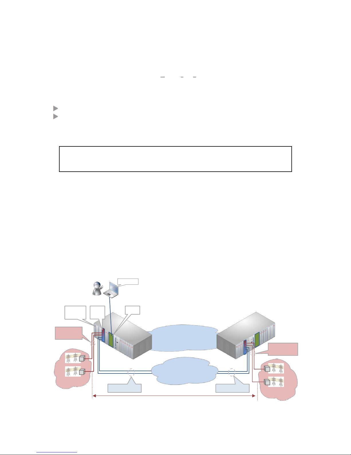
The E1 links provide synchronous TDM links between two end points that can be used to
transport over an external network e.g. SDH. The optical ports are the access ports whereas
the E1 ports are the SDH interconnection ports. At the destination side, the 2-OLS receives
the E1 traffic and converts it back to an optical low speed serial signal towards the end
application.
In HiProvision (=Dragon PTN Management), an 'Optical Low Speed Serial' service can be
configured between two optical ports, each port located in a different node. This service
bundles together 32 TDM (Time Division Multiplex) connections resulting in a total
bandwidth of 2.048 Mbps. The E1 side can slave its clock for example to the E1 clock from
the external network.
NOTE: HiProvision can be configured redundantly.
Figure 1 2-OLS - SDH Example
HiProvision
Dragon
PTN Node
2-OLS
IFM
CSM
Optical Serial
Fiber Links
Dragon PTN MPLS-TP
Network
Optical Serial
Fiber Links
External Network
Example: SDH
Teleprotection1
External E1 Links
External E1 Links
Teleprotection2
'Optical Low Speed Serial' Service
CAUTION: This IFM is only a convertor module that needs to be powered via the
node. It will not have backplane or Dragon PTN network access. The MPLS-TP Dragon PTN network is not required (or optional) for this IFM to operate.
Interface Module PTN-2-OLS with E1/PTN-2-OLS with T
Release 01 02/2018
5
Page 6

The main supported features are:
No Dragon PTN network access;
Converting optical serial into E1 and vice versa;
Point-to-point connection;
E1 port on 2-OLS IFM can slave to E1 clock from external network;
Services: Optical Low Speed Serial in HiProvision;
Synchronous/asynchronous serial communication;
1.2 Manual References
Table 1 is an overview of the manuals referred to in this manual. ‘&’ refers to the language
code, ‘*’ refers to the manual issue. All these manuals can be found in the HiProvision
(=Dragon PTN Management System) Help function.
Table 1 Manual References
Ref. Number Title
[1] DRA-DRM821-&-* Dragon PTN and HiProvision Operation
[2] DRA-DRM801-&-* Dragon PTN Installation and Operation
[3] DRB-DRM802-&-* Dragon PTN Nodes: PTN2210, PTN2209, PTN2206, PTN1104
[4] DRB-DRM803-&-* Dragon PTN Switching Module: PTN-CSM310-A
[5] DRA-DRM810-&-* Dragon PTN General Specifications
2. MODULE DESCRIPTION
2.1 Front Panel
Figure 2 Front Panel
Fastening screw
Handle
LEDs
2 OLS
Ports
2 E1/T1
Ports
6 Interface Module PTN-2-OLS with E1/PTN-2-OLS with T
Release 01 02/2018
Page 7

2.1.1 Handle
a. Insert the Module into the Node
Take the front panel handles to insert or slide the module into the Dragon PTN node. Push
the module thoroughly into the node’s backplane. Next, tighten the two fastening screws in
the front panel corners.
b. Remove the Module from the Node
Untighten the two fastening screws in the front panel corners. Take the front panel handles
to pull out and finally remove the module from the Dragon PTN node.
2.1.2 LEDs
The meaning of the LEDs depends on the mode of operation (= boot or normal) in which the
2-OLS module currently is running. After plugging in the module or rebooting it, the module
turns into the boot operation, see Table 2. After the module has gone through all the cycles
in the table below (=rebooted successfully), the module turns into the normal operation, see
LEDs in Table 3.
Table 2 LED Indications In Boot Operation
Cycle PI PF FLT Spare LED RX[1,2] TX[1,2] AIS[3,4] LOS[3,4]
1 x --- Slow blinking --- --- --- --- ---
2 x --- Fast blinking --- --- --- --- ---
3 x --- --- --- --- --- --- ---
4 x --- Fast blinking --- x x x x
x : LED is lit
--- : LED is not lit
The sub cycle times may vary.
The entire boot cycle time [14] takes approximately 2 minutes.
Table 3 LED Indications In Normal Operation
LED Color Status
PI
(=Power Input)
Not lit, dark +12V power input to the board not OK
Green +12V power input to the board OK
PF
(=Power
Failure)
Not lit, dark power generation on the board itself is OK
Red power generation on the board itself is erroneous
FLT (=FauLT) Not lit, dark no other fault or error situation, different from PF, is active on the module
Red a fault or error situation, different from PF, is active on the module
RX<port n°> Not lit, dark no service programmed on this optical serial port
Green, blinking Service programmed, no optical serial port activity detected
Green, lit Service programmed, optical serial port activity detected
TX<port n°> Not lit, dark No service programmed on this optical serial port
Green, blinking Service programmed, optical serial port not sending out data
Green, lit Service programmed, optical serial port sending out data, no errors
Interface Module PTN-2-OLS with E1/PTN-2-OLS with T
Release 01 02/2018
7
Page 8

LED Color Status
AIS<port n°>
(=Alarm
Indication
Signal)
Not lit, dark - no service on this port
- service on this port: no alarms detected on backplane (=network) side, everything fine
Red, lit service on this port: no network traffic or TX AIS detected on backplane (=network) side
Red, blinking other errors different from TX AIS detected on backplane (=network) side
LOS<port n°>
(Loss of Signal)
Not lit, dark - no service on this port
- service on this port: local E1 traffic on this front port is OK
Red, lit service on this port: local E1 signal is lost on this front port
Red, blinking AIS, LOF or RAI received on this front port
2.1.3 Optical Serial Port (Fiber)
The 2-OLS module provides two optical serial ports with each port having two ST (=Straight
Tip) connectors: TX and RX. These ports can be used for communication over optical fiber.
Figure 3 Optical Serial ST Connector
2.1.4 E1 RJ-45 Ports (Copper) and Cables
The 2-OLS module provides two E1 ports and each port connector has eight pins. Each port
provides one tip/ring pair. See the table and figure below for an overview and description.
The cables below can be ordered to connect these ports.
E1 cable (120 Ω): ordering number 942 256-201.
Figure 4 E1 RJ-45 Connector
Table 4 E1 RJ-45 Connector: Pin Assignments
Pin Number Description Cable Wire Colors
1 Rx (Receive) RING OG
2 Rx (Receive) TIP WH/OG
3 Not connected -
4 Tx (Transmit) RING BU
5 Tx (Transmit) TIP WH/BU
6, 7 ,8 Not connected -
1 8
8 Interface Module PTN-2-OLS with E1/PTN-2-OLS with T
Release 01 02/2018
Page 9

2.2 Functional Operation
2.2.1 General
See §1.1.
2.2.2 E1 Framing
E1 is a 2.048 Mbps bi-directional (full duplex) link through which the data is transported in a
digital way in frames. One frame consists of 32 time slots (Figure 5). Timeslot 0 is used for
framing and synchronization, and time slot 16 for signaling. The bandwidth of one time slot
is 64 kbps (=8 bits/125 µs). One frame thus consists of 32*8 = 256 bits and lasts
125 µs. Typically 16 frames are packed together in one multiframe.
NOTE: Multiframe = future support;
Frame = 125 µs = 32 time slots
Bit slot
Time slot
Frame
Figure 5 E1 Framing
2.2.3 E1 Coding: AMI, HDB3
AMI, HDB3 are different types of line coding. HDB3 is used in E1. The 2-OLS module supports
HDB3 for E1. HDB3 is an enhancement of AMI. For this reason, AMI is mentioned here as
well.
As the E1 link has no separate clock transmission, the receiver will derive the clock from the
incoming data stream. A minimum density of logical ones is required in order to guarantee a
faultless clock recovery. This is achieved basically by AMI which encodes the data stream
with bipolar violations. A more enhanced and better encoding is HDB3 which enhances the
AMI stream by replacing successive zeros:
E1 HDB3: replace four successive zeros with a fixed bit pattern ‘000V’ or ‘B00V’;
A ‘B’ and ‘V’ can either be ‘-‘ or ‘+’. Which pattern is used depends on the amount of ‘+’ and
‘-‘ already received from send on the link.
...0000...
...000V... ...B00V...
Figure 6 HDB3 Encoding
F
0 1 2
S
16
31
F = Framing
S = Signaling
1
16 1
Multiframe = 2 ms
E1: HDB3 Encoding :
replace 4 zeros with 000V or B00V
Interface Module PTN-2-OLS with E1/PTN-2-OLS with T
Release 01 02/2018
9
Page 10

2.2.4 FM0 Coding (Biphase Space Encoding)
FM0 Coding is a biphase 'space' encoding ('space' = 0-bit; 'mark' : 1-bit) that can be used in
serial data communication. FM0 encoding guarantees to have a transition (from high to low
or vice versa) in every data bit. This encoded data contains sufficient transitions to recover a
clock from the data. Further advantages are the DC balancing resulting in enhanced signal
reliability.
With FM0 Coding enabled, a 0-bit (='space') will always have an extra transition halfway its
bit time (=2 phases = biphase) whereas a 1-bit will have no transition within its bit time.
(Normal) Data
FM0 Encoded Data
0 0 1 1
0 1 0 1 0 1
1
1
0
1
0
bit time
Figure 7 FM0 Coding
FM0 Coding:
disabled (=default): Normal data (without encoding) is expected at the optical serial RX
ports. Normal data (without encoding) is generated at the optical serial TX ports;
enabled: FM0 encoded data is expected at the optical serial RX ports. FM0 encoded data
is generated at the optical serial TX ports;
2.2.5 Short Haul/Long Haul on E1 Ports
Long E1 links (>200m, Long Haul) have more signal attenuation than shorter links (<200m,
Short Haul). As a result, the signal levels or sensitivity ('0' or '1') on the receiver side must be
configured according the used link: Long Haul or Short Haul.
In HiProvision, a Short Haul parameter can be checked for Short Haul links and unchecked
(=default) for Long Haul links. This parameter can be set on port level in the IFM or at service
creation.
2.2.6 Service: Optical Low Speed Serial
The 'Optical Low Speed Serial service' is a point-to-point service between two optical serial
ports, each port located in a different node, see §1.1. This service can be configured in
HiProvision (=Dragon PTN management system). It converts the incoming serial signal into
E1 and vice versa.
Within one 2-OLS IFM, [port 1 <-> port3] and [port 2 <-> port4] are always linked via a fixed
local loopback including the conversion. See next figure:
10 Interface Module PTN-2-OLS with E1/PTN-2-OLS with T
Release 01 02/2018
Page 11

Optical
Serial
Port1
Optical
Serial
Port2
Hardware
Edition
E1/T1 Configuration
(future)
Fixed Local Loopback
port1 <-> port3
with serial <-> E1 conversion
E1
Port3
E1
Port4
Fixed Local Loopback
port2 <-> port4
with serial <-> E1 conversion
Figure 8 2-OLS IFM Side View: Local Loopbacks
Following can be configured during service creation:
Optical Serial Ports:
Synchronisation: synchronous or asynchronous;
Synchronous:
Bitrate: [64 (=1*64), 128 (=2*64), 512(=8*64), 1984(=31*64)] kbps;
FM0 Coding (see §2.2.4): disabled/enabled;
Asynchronous:
Bitrate: [1200, 2400, 4800, 9600, 19200, 38400, 57600, 76800, 115200, 297600]
bps; When a bit rate is selected, an incoming serial signal with a lower bitrate
will operate as well, because 2-OLS samples at 6.6 times the selected bitrate;
E1 Ports:
Short Haul (see §2.2.5): unchecked (=default) /checked;
2.2.7 I/O with the Central Switching Module (=CSM)
The CSM is only needed to program the 2-OLS IFM via HiProvision. Once the 2-OLS IFM has
been configured, it does not need the CSM anymore.
2.2.8 Test and Loopback Selftests
Test and Loopback selftests can be performed (via HiProvision) in CESes, e.g when
configuring or troubleshooting a CES. Following two functions can be used in a programmed
CES:
Loopbacks: on backplane or front port, direction towards line (=application) or network
can be configured;
BERT: test traffic generation and verification via Bit Error Ratio Tester.
E1
E1
Optical
Serial
Optical
Serial
E1
T1
SW2 SW3 SW4 SW5 SW6 SW7 SW8
Interface Module PTN-2-OLS with E1/PTN-2-OLS with T
Release 01 02/2018
11
Page 12

2.3 Onboard Interfaces
See Figure 8 for a side view of the IFM module.
2.3.1 Straps
No user relevant straps.
2.3.2 DIP Switches
a. Hardware Edition
The Hardware Edition is set in decimal code using rotary switches S2 to S3 (=most
significant). It can be read out as well via HiProvision. This edition has been factory set and
MUST NOT BE CHANGED!
Example: Setting S3=’0’ and S2=’5’ indicates Hardware Edition ‘5’ (dec).
Figure 9 Hardware Edition
b. E1/T1 Configuration
The E1/T1 configuration of the 2-OLS module is factory set by the S1 DIP switch into E1
mode and must not be changed. The configuration can be read out via HiProvision.
Switch = E1: both E1/T1 ports operate as E1 ports, use the ‘2-OLS-E1-L’ IFM in
HiProvision;
Switch = T1 (=future): both E1/T1 ports operate as T1 ports, use the ‘2-OLS-T1-L’ IFM in
HiProvision.
Figure 10 E1/T1 Configuration
E1
E1/T1
Configuration
T1
SW2
SW3
SW4
SW5
SW6
SW7
SW8
12 Interface Module PTN-2-OLS with E1/PTN-2-OLS with T
Release 01 02/2018
Page 13

3. MODULE SPECIFICATIONS
3.1 General Specifications
For general specifications like temperature, humidity, EMI... see Ref.[5] in Table 1.
3.2 Other Specifications
Table 5 Other Specifications
Description Value
Weight 0.23 kg / 0.5 lb
MTBF 87 years at 25°C/77°F
Power Consumption 8.4 W (measured at 25°C/77°F)
Module Size
width:
20.32 mm / 0.8 inches
height:
126 mm / 4.96 inches
depth:
195 mm / 7.68 inches
3.3 Ordering Information
2-OLS with E1: future support;
2-OLS with T1: future support;
4. ABBREVIATIONS
AIS
Alarm Indication Signal
AMI
Alternate Mark Inversion
CE Conformité Européenne
CSM
Central Switching Module
DC Direct Current
EMI
Electromagnetic Interference
ERR
Error
ETH
Ethernet
FLT
Fault
HDB3
High Density Bipolar of Order 3
IEEE
Institute of Electrical and Electronics Engineers
IFM
InterFace Module
kbps
Kilobit per Second
LAN
Local Area Network
LOF
Loss Of Framing
LOS
Loss Of Signal
LVD
Low Voltage Directive
Interface Module PTN-2-OLS with E1/PTN-2-OLS with T
Release 01 02/2018
13
Page 14

Mbps
Megabit per Second
MPLS-TP
MultiProtocol Label Switching – Transport Profile
MSB
Most Significant Bit
MTBF
Mean Time Between Failures
OLS
Optical Low Speed
PF Power Failure
PI
Power Input
PTN
Packet Transport Network
PTP Point to Point
RAI
Remote Alarm Indicator
SDH
Synchronous Digital Hierarchy
SF
Super Frame
ST
Straight Tip
TDM Time Division Multiplex
14 Interface Module PTN-2-OLS with E1/PTN-2-OLS with T
Release 01 02/2018
 Loading...