

Hirschmann PowerLION-24TP Installation Manual

Installation Guide
Gigabit ETHERNET Layer 3 Switch
PowerLION-24TP
Installation Guide
PowerLION-24TP
Release 1.0 02/06
Technische Unterstützung
www.edge-core.com
HAC-Support@hirschmann.de

The naming of copyrighted trademarks in this manual, even when not specially indicated, should
not be taken to mean that these names may be considered as free in the sense of the trademark
and tradename protection law and hence that they may be freely used by anyone.
© 2006 Hirschmann Automation and Control GmbH
Manuals and software are protected by copyright. All rights reserved. The copying, reproduction,
translation, conversion into any electronic medium or machine scannable form is not permitted,
either in whole or in part. An exception is the preparation of a backup copy of the software for
your own use.
The performance features described here are binding only if they have been expressly
guaranteed in the contract. This publication has been created by Hirschmann Automation and
Control GmbH according to the best of our knowledge. Hirschmann reserves the right to change
the contents of this manual without prior notice. Hirschmann can give no guarantee in respect
of the correctness or accuracy of the details in this publication.
Hirschmann can accept no responsibility for damages, resulting from the use of the network
components or the associated operating software. In addition, we refer to the conditions of use
specified in the license contract.
Printed in Germany (2/23/06)
Hirschmann Automation and Control GmbH
Stuttgarter Straße 45-51
72654 Neckartenzlingen
Telefon +49 1805 141538 -0206

Installation Guide
Gigabit Ethernet Switch
Layer 3 Switch with
20 1000BASE-T (RJ-45) Ports,
4 Combination Ports (RJ-45/SFP),
1 Extender Module Slot, and
2 Stacking Ports


Compliances and Safety Warnings
FCC - Class A
This equipment generates, uses, and can radiate radio frequency energy and, if not
installed and used in accordance with the instruction manual, may cause interference to
radio communications. It has been tested and found to comply with the limits for a Class A
computing device pursuant to Subpart B of Part 15 of FCC Rules, which are designed to
provide reasonable protection against such interference when operated in a commercial
environment. Operation of this equipment in a residential area is likely to cause
interference, in which case the user, at his own expense, will be required to take whatever
measures may be required to correct the interference. You are cautioned that changes or
modifications not expressly approved by the party responsible for compliance could void
your authority to operate the equipment.
You may use unshielded twisted-pair (UTP) for RJ-45 connections - Category 3 or better
for 10 Mbps connections, Category 5 or better for 100 Mbps connections, Category 5, 5e,
or 6 for 1000 Mbps connections. For fiber optic connections, you may use 50/125 or 62.5/
125 micron multimode fiber or 9/125 micron single-mode fiber.
Warnings: 1. Wear an anti-static wrist strap or take other suitable measures to prevent
electrostatic discharge when handling this equipment.
2. When connecting this hub to a power outlet, connect the field ground lead
on the tri-pole power plug to a valid earth ground line to prevent electrical
hazards.
Industry Canada - Class A
This digital apparatus does not exceed the Class A limits for radio noise emissions from
digital apparatus as set out in the interference-causing equipment standard entitled
“Digital Apparatus,” ICES-003 of the Department of Communications.
Cet appareil numérique respecte les limites de bruits radioélectriques applicables aux
appareils numériques de Classe A prescrites dans la norme sur le matériel brouilleur:
“Appareils Numériques,” NMB-003 édictée par le ministère des Communications.
Japan VCCI Class A
i

CE Mark Declaration of Conformance for EMI and Safety (EEC)
This information technology equipment complies with the requirements of the Council
Directive 89/336/EEC on the Approximation of the laws of the Member States relating to
Electromagnetic Compatibility and 73/23/EEC for electrical equipment used within certain
voltage limits and the Amendment Directive 93/68/EEC. For the evaluation of the
compliance with these Directives, the following standards were applied:
RFI Emission: • Limit class A according to EN 55022:1998
• Limit class A for harmonic current emission according to EN 61000-3-2/1995
• Limitation of voltage fluctuation and flicker in low-voltage supply system
according to EN 61000-3-3/1995
Immunity: • Product family standard according to EN 55024:1998
• Electrostatic Discharge according to EN 61000-4-2:1995
(Contact Discharge: ±4 kV, Air Discharge: ±8 kV)
• Radio-frequency electromagnetic field according to EN 61000-4-3:1996
(80 - 1000 MHz with 1 kHz AM 80% Modulation: 3 V/m)
• Electrical fast transient/burst according to EN 61000-4-4:1995 (AC/DC power
supply: ±1 kV, Data/Signal lines: ±0.5 kV)
• Surge immunity test according to EN 61000-4-5:1995
(AC/DC Line to Line: ±1 kV, AC/DC Line to Earth: ±2 kV)
• Immunity to conducted disturbances, Induced by radio-frequency fields:
EN 61000-4-6:1996 (0.15 - 80 MHz with 1 kHz AM 80% Modulation: 3 V/m)
• Power frequency magnetic field immunity test according to
EN 61000-4-8:1993
(1 A/m at frequency 50 Hz)
• Voltage dips, short interruptions and voltage variations immunity test
according to EN 61000-4-11:1994 (>95% Reduction @10 ms, 30%
Reduction @500 ms, >95% Reduction @5000 ms)
LVD: • EN 60950:2000
Caution: Do not plug a phone jack connector in the RJ-45 port. This may damage this
device.
Attention: Les raccordeurs ne sont pas utilisés pour le système téléphonique!
Australia AS/NZS 3548 (1995) - Class A
ACN 066 352 010
ii

Safety Compliance
Warning: Fiber Optic Port Safety
When using a fiber optic port, never look at the transmit laser while it is
CLASS I
LASER DEVICE
powered on. Also, never look directly at the fiber TX port and fiber cable
ends when they are powered on.
Avertissment: Ports pour fibres optiques - sécurité sur le plan optique
Ne regardez jamais le laser tant qu'il est sous tension. Ne regardez
DISPOSITIF LASER
DE CLASSE I
jamais directement le port TX (Transmission) à fibres optiques et les
embouts de câbles à fibres optiques tant qu'ils sont sous tension.
Warnhinweis: Faseroptikanschlüsse - Optische Sicherheit
LASERGER
DER KLASSE I
ÄT
Niemals ein Übertragungslaser betrachten, während dieses
eingeschaltet ist. Niemals direkt auf den Faser-TX-Anschluß
und auf die Faserkabelenden schauen, während diese
eingeschaltet sind.
Please read the following safety information carefully before
installing the switch:
WAR NING: Installation and removal of the unit must be carried out by qualified personnel
only.
• The unit must be connected to an earthed (grounded) outlet to comply with international
safety standards.
• Do not connect the unit to an A.C. outlet (power supply) without an earth (ground)
connection.
• The appliance coupler (the connector to the unit and not the wall plug) must have a
configuration for mating with an EN 60320/IEC 320 appliance inlet.
• The socket outlet must be near to the unit and easily accessible. You can only remove
power from the unit by disconnecting the power cord from the outlet.
• This unit operates under SELV (Safety Extra Low Voltage) conditions according to
IEC 60950. The conditions are only maintained if the equipment to which it is connected
also operates under SELV conditions.
France and Peru only
This unit cannot be powered from IT† supplies. If your supplies are of IT type, this unit
must be powered by 230 V (2P+T) via an isolation transformer ratio 1:1, with the
secondary connection point labelled Neutral, connected directly to earth (ground).
†
Impédance à la terre
iii

Power Cord Set
U.S.A. and Canada The cord set must be UL-approved and CSA certified.
The minimum specifications for the flexible cord are:
- No. 18 AWG - not longer than 2 meters, or 16 AWG.
- Type SV or SJ
- 3-conductor
The cord set must have a rated current capacity of at least 10 A
The attachment plug must be an earth-grounding type with NEMA
5-15P (15 A, 125 V) or NEMA 6-15P (15 A, 250 V) configuration.
Denmark The supply plug must comply with Section 107-2-D1, Standard
DK2-1a or DK2-5a.
Switzerland The supply plug must comply with SEV/ASE 1011.
U.K. The supply plug must comply with BS1363 (3-pin 13 A) and be fitted
with a 5 A fuse which complies with BS1362.
The mains cord must be <HAR> or <BASEC> marked and be of type
HO3VVF3GO.75 (minimum).
Europe The supply plug must comply with CEE7/7 (“SCHUKO”).
The mains cord must be <HAR> or <BASEC> marked and be of type
HO3VVF3GO.75 (minimum).
IEC-320 receptacle.
Veuillez lire à fond l'information de la sécurité suivante avant
d'installer le Switch:
AVERTISSEMENT: L’installation et la dépose de ce groupe doivent être confiés à un
personnel qualifié.
• Ne branchez pas votre appareil sur une prise secteur (alimentation électrique) lorsqu'il
n'y a pas de connexion de mise à la terre (mise à la masse).
• Vous devez raccorder ce groupe à une sortie mise à la terre (mise à la masse) afin de
respecter les normes internationales de sécurité.
• Le coupleur d’appareil (le connecteur du groupe et non pas la prise murale) doit
respecter une configuration qui permet un branchement sur une entrée d’appareil EN
60320/IEC 320.
• La prise secteur doit se trouver à proximité de l’appareil et son accès doit être facile.
Vous ne pouvez mettre l’appareil hors circuit qu’en débranchant son cordon électrique
au niveau de cette prise.
• L’appareil fonctionne à une tension extrêmement basse de sécurité qui est conforme à
la norme IEC 60950. Ces conditions ne sont maintenues que si l’équipement auquel il
est raccordé fonctionne dans les mêmes conditions.
iv

France et Pérou uniquement:
Ce groupe ne peut pas être alimenté par un dispositif à impédance à la terre. Si vos
alimentations sont du type impédance à la terre, ce groupe doit être alimenté par une
tension de 230 V (2 P+T) par le biais d’un transformateur d’isolement à rapport 1:1, avec
un point secondaire de connexion portant l’appellation Neutre et avec raccordement
direct à la terre (masse).
Cordon électrique - Il doit être agréé dans le pays d’utilisation
Etats-Unis et
Canada:
Danemark: La prise mâle d’alimentation doit respecter la section 107-2 D1 de la
Suisse: La prise mâle d’alimentation doit respecter la norme SEV/ASE 1011.
Europe La prise secteur doit être conforme aux normes CEE 7/7 (“SCHUKO”)
Le cordon doit avoir reçu l’homologation des UL et un certificat de la
CSA.
Les spe'cifications minimales pour un cable flexible sont AWG No.
18, ouAWG No. 16 pour un cable de longueur infe'rieure a` 2 me'tres.
- type SV ou SJ
- 3 conducteurs
Le cordon doit être en mesure d’acheminer un courant nominal d’au
moins 10 A.
La prise femelle de branchement doit être du type à mise à la terre
(mise à la masse) et respecter la configuration NEMA 5-15P (15 A,
125 V) ou NEMA 6-15P (15 A, 250 V).
norme DK2 1a ou DK2 5a.
LE cordon secteur doit porter la mention <HAR> ou <BASEC> et doit
être de type HO3VVF3GO.75 (minimum).
Bitte unbedingt vor dem Einbauen des Switches die folgenden
Sicherheitsanweisungen durchlesen:
WARNUNG: Die Installation und der Ausbau des Geräts darf nur durch Fachpersonal
erfolgen.
• Das Gerät sollte nicht an eine ungeerdete Wechselstromsteckdose angeschlossen
werden.
• Das Gerät muß an eine geerdete Steckdose angeschlossen werden, welche die
internationalen Sicherheitsnormen erfüllt.
• Der Gerätestecker (der Anschluß an das Gerät, nicht der Wandsteckdosenstecker) muß
einen gemäß EN 60320/IEC 320 konfigurierten Geräteeingang haben.
• Die Netzsteckdose muß in der Nähe des Geräts und leicht zugänglich sein. Die
Stromversorgung des Geräts kann nur durch Herausziehen des Gerätenetzkabels aus
der Netzsteckdose unterbrochen werden.
• Der Betrieb dieses Geräts erfolgt unter den SELV-Bedingungen
(Sicherheitskleinstspannung) gemäß IEC 60950. Diese Bedingungen sind nur gegeben,
wenn auch die an das Gerät angeschlossenen Geräte unter SELV-Bedingungen
betrieben werden.
v

Stromkabel. Dies muss von dem Land, in dem es benutzt wird geprüft werden:
Schweiz Dieser Stromstecker muß die SEV/ASE 1011Bestimmungen einhalt-
en.
Europe Das Netzkabel muß vom Typ HO3VVF3GO.75 (Mindestanforderung)
sein und die Aufschrift <HAR> oder <BASEC> tragen.
Der Netzstecker muß die Norm CEE 7/7 erfüllen (”SCHUKO”).
Warnings and Cautionary Messages
Warning: This product does not contain any serviceable user parts.
Warning: Installation and removal of the unit must be carried out by qualified
personnel only.
Warning: When connecting this device to a power outlet, connect the field ground lead
on the tri-pole power plug to a valid earth ground line to prevent electrical
hazards.
Warning: This switch uses lasers to transmit signals over fiber optic cable. The lasers
are compliant with the requirements of a Class 1 Laser Product and are
inherently eye safe in normal operation. However, you should never look
directly at a transmit port when it is powered on.
Caution: Wear an anti-static wrist strap or take other suitable measures to prevent
electrostatic discharge when handling this equipment.
Caution: Do not plug a phone jack connector in the RJ-45 port. This may damage this
device. Les raccordeurs ne sont pas utilisé pour le système téléphonique!
Caution: Use only twisted-pair cables with RJ-45 connectors that conform to FCC
standards.
Warnings (In German)
Achtung:
Achtung: Wenn das Gerät an eine Steckdose angeschlossen wird, muß der
Achtung: Dieses Gerät nutzt Laser zur Signalübertragung über Glasfasern. Die Laser
Dieses Produkt enthält keine Teile, die eine Wartung vom Benutzer
benötigen.
Masseanschluß am dreipoligen Netzstecker mit Schutzerde verbunden
werden, um elektrische Gefahren zu vermeiden.
entsprechen den Anforderungen an eine Lasereinrichtung der Klasse 1 und
sind durch ihre Bauart im normalen Betrieb sicher für die Augen. Trotzdem
sollte niemals direkt in den einen Übertragungskanal geblickt werden, wenn
er eingeschaltet ist.
vi

Environmental Statement
The manufacturer of this product endeavours to sustain an environmentally-friendly policy
throughout the entire production process. This is achieved though the following means:
• Adherence to national legislation and regulations on environmental production
standards.
• Conservation of operational resources.
• Waste reduction and safe disposal of all harmful un-recyclable by-products.
• Recycling of all reusable waste content.
• Design of products to maximize recyclables at the end of the product’s life span.
• Continual monitoring of safety standards.
End of Product Life Span
This product is manufactured in such a way as to allow for the recovery and disposal of all
included electrical components once the product has reached the end of its life.
Manufacturing Materials
There are no hazardous nor ozone-depleting materials in this product.
Documentation
All printed documentation for this product uses biodegradable paper that originates from
sustained and managed forests. The inks used in the printing process are non-toxic.
Purpose
This guide details the hardware features of the PowerLION-24TP switches, including their
physical and performance-related characteristics, and how to install each switch.
Audience
This guide is for system administrators with a working knowledge of network
management. You should be familiar with switching and networking concepts.
Zielgruppe Dieser Anleitung ist fuer Systemadministratoren mit Erfahrung im
Netzwerkmangement. Sie sollten mit Switch- und Netzwerkkonzepten vertraut sein.
Related Publications
The following publication gives specific information on how to operate and use the
management functions of the switches:
The Gigabit Ethernet Switch Management Guide
Also, as part of both switches’ firmware, there is an online web-based help that describes
all management related features.
vii

viii

Contents
Chapter 1: Introduction 1-1
Overview 1-1
Switch Architecture 1-2
Network Management Options 1-2
Description of Hardware 1-3
10/100/1000BASE-T Ports 1-3
SFP Slots 1-3
Stacking Ports 1-3
Port and System Status LEDs 1-4
Optional Redundant Power Unit 1-6
Power Supply Sockets 1-6
Optional Media Extender Module 1-6
Extender Module LEDs 1-7
Features and Benefits 1-7
Connectivity 1-7
Expandability 1-7
Performance 1-8
Management 1-8
Chapter 2: Network Planning 2-1
Introduction to Switching 2-1
Application Examples 2-2
Collapsed Backbone 2-2
Network Aggregation Plan 2-3
Remote Connections with Fiber Cable 2-4
Making VLAN Connections 2-5
Using Layer 3 Routing 2-6
Application Notes 2-7
Chapter 3: Installing the Switch 3-1
Selecting a Site 3-1
Ethernet Cabling 3-1
Equipment Checklist 3-2
Package Contents 3-2
Optional Rack-Mounting Equipment 3-2
Mounting 3-3
Rack Mounting 3-3
Desktop or Shelf Mounting 3-4
ix

Contents
Installing an Optional Module into the Switch 3-5
Installing an Optional SFP Transceiver 3-6
Connecting Switches in a Stack 3-6
Stacking Topologies 3-8
Connecting to a Power Source 3-8
Connecting to the Console Port 3-9
Wiring Map for Serial Cable 3-9
Chapter 4: Making Network Connections 4-1
Connecting Network Devices 4-1
Twisted-Pair Devices 4-1
Cabling Guidelines 4-1
Connecting to PCs, Servers, Hubs and Switches 4-2
Network Wiring Connections 4-2
Fiber Optic SFP Devices 4-3
10 Gbps Fiber Optic Connections 4-4
Connectivity Rules 4-5
1000BASE-T Cable Requirements 4-5
10 Gbps Ethernet Collision Domain 4-6
1000 Mbps Gigabit Ethernet Collision Domain 4-7
100 Mbps Fast Ethernet Collision Domain 4-7
10 Mbps Ethernet Collision Domain 4-7
Cable Labeling and Connection Records 4-8
Appendix A: Troubleshooting A-1
Diagnosing Switch Indicators A-1
Diagnosing Power Problems with the LEDs A-1
Power and Cooling Problems A-2
Installation A-2
In-Band Access A-2
Stack Troubleshooting A-3
Appendix B: Cables B-1
Twisted-Pair Cable and Pin Assignments B-1
10BASE-T/100BASE-TX Pin Assignments B-1
Straight-Through Wiring B-2
Crossover Wiring B-2
1000BASE-T Pin Assignments B-3
Cable Testing for Existing Category 5 Cable B-4
Adjusting Existing Category 5 Cabling to Run 1000BASE-T B-4
Fiber Standards B-4
x

Contents
Appendix C: Specifications C-1
Physical Characteristics C-1
Switch Features C-2
Management Features C-2
Standards C-3
Compliances C-3
Extender Modules C-3
10G Xenpak Extender Module (Xenpak) C-3
Installationsort Auswählen
(Selecting a Site - German) B-1
Montage (Rack Mounting Instructions - German) B-2
Schaltschrank-Montage B-2
xi

Contents
Glossary
Index
xii

Tables
Table 1-1 Port Status LEDs 1-4
Table 1-2 System Status LEDs 1-5
Table 1-3 Module LEDs 1-7
Table 3-1 Serial Cable Wiring 3-9
Table 4-1 Maximum 10GBASE-SR 10 Gigabit Ethernet Cable Length 4-6
Table 4-2 Maximum 10GBASE-ER 10 Gigabit Ethernet Cable Length 4-6
Table 4-3 Maximum 10GBASE-LR 10 Gigabit Ethernet Cable Length 4-6
Table 4-4 Maximum 1000BASE-T Gigabit Ethernet Cable Length 4-7
Table 4-5 Maximum 1000BASE-SX Gigabit Ethernet Cable Length 4-7
Table 4-6 Maximum 1000BASE-LX Gigabit Ethernet Cable Length 4-7
Table 4-7 Maximum 1000BASE-LH Gigabit Ethernet Cable Length 4-7
Table 4-8 Maximum Fast Ethernet Cable Length 4-7
Table 4-9 Maximum Ethernet Cable Length 4-7
Table A-1 Troubleshooting Chart A-1
Table A-2 Power/RPU LEDs A-1
Table B-1 10/100BASE-TX MDI and MDI-X Port Pinouts B-2
Table B-2 1000BASE-T MDI and MDI-X Port Pinouts B-3
xiii

Tables
xiv

Figures
Figure 1-1 PowerLION-24TP Front Panel 1-1
Figure 1-2 PowerLION-24TP Rear Panel 1-2
Figure 1-3 Port LEDs 1-4
Figure 1-4 System LEDs 1-5
Figure 1-5 Power Supply Sockets 1-6
Figure 1-6 Single-Port 10G Module (Xenpak) 1-6
Figure 2-1 Collapsed Backbone 2-2
Figure 2-2 Network Aggregation Plan 2-3
Figure 2-3 Remote Connection with Fiber Cable 2-4
Figure 2-4 Making VLAN Connections 2-5
Figure 2-5 IP Routing for Unicast Traffic 2-6
Figure 3-1 RJ-45 Connections 3-2
Figure 3-2 Attaching the Brackets 3-3
Figure 3-3 Installing the Switch in a Rack 3-4
Figure 3-4 Attaching the Adhesive Feet 3-4
Figure 3-5 Installing an Optional Module 3-5
Figure 3-6 Inserting an SFP Transceiver into a Slot 3-6
Figure 3-7 Making Stacking Connections 3-7
Figure 3-8 Power Receptacle 3-8
Figure 3-9 Serial Port (DB-9 DTE) Pin-Out 3-9
Figure 4-1 Making Twisted-Pair Connections 4-2
Figure 4-2 Network Wiring Connections 4-3
Figure 4-3 Making Connections to SFP Transceivers 4-4
Figure 4-4 Making SC Port Connection to Xenpak Transceiver 4-5
Figure B-1 RJ-45 Connector Pin Numbers B-1
Figure B-2 Straight-through Wiring B-2
Figure B-3 Crossover Wiring B-3
xv

Figures
xvi
Chapter 1: Introduction
Overview
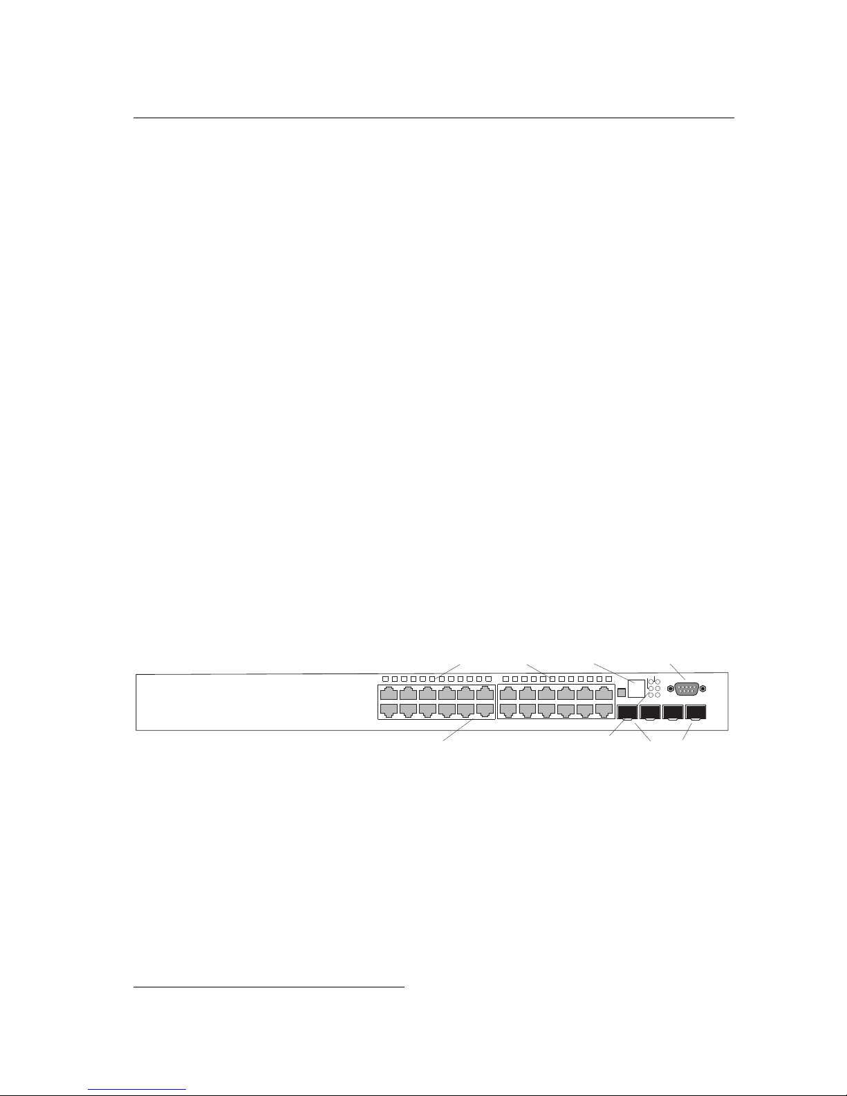
The Gigabit Ethernet Switches are intelligent multilayer switches (Layer 2, 3) with
24 10/100/1000BASE-T ports, four of which are combination ports
with four SFP transceiver slots (see Figure 1-1, Ports 21-24). The rear panel
provides a slot for single-port 10 Gigabit Ethernet hot-swappable expansion module,
and two stacking ports. Units are stackable up to eight high through built-in stacking
ports that provide a 40 Gbps stack backplane.
The switch systems include an SNMP-based management agent embedded on the
main board, which supports both in-band and out-of-band access for managing the
switch stack.
This switch system can easily tame your network with full support for Spanning Tree
Protocol, Multicast Switching, Virtual LANs, and IP routing. They bring order to
poorly performing networks by segregating them into separate broadcast domains
with IEEE 802.1Q compliant VLANs, empower multimedia applications with
multicast switching and CoS services, and eliminate conventional router
bottlenecks.
*
that are shared
These switches can be used to augment or completely replace slow legacy routers,
off-loading local IP traffic to release valuable resources for non-IP routing or WAN
access. With wire-speed performance for Layer 2 and Layer 3, these switches can
significantly improve the throughput between IP segments or VLANs.
4
12
5
3
89
6
7
10/100/1000 Mbps RJ-45 Por ts
Por t S tatus LEDs
12
10
11
15
14
13
System Status LEDs
17
16
Stack ID
18
21
20
19
Serial Console Por t
Stack Link
Stack ID
23 24
22
Master
Select
25
Stack Master
Power
RPU
Diag
Module
27
26
SFP Slots
Console
28
Figure 1-1 PowerLION-24TP Front Panel
* If an SFP transceiver is plugged in, the corresponding RJ-45 port is disabled for ports
21-24.
1-1

1
Power Socket
Introduction
100-240V~
50-60Hz 2A
DC
12V13A
Module
RPU
Up
Down
R edundant P ower S ocket
Module S lot
StackingPorts
Figure 1-2 PowerLION-24TP Rear Panel
Switch Architecture
The Gigabit Ethernet Switches employ a wire-speed, non-blocking switching fabric.
This permits simultaneous wire-speed transport of multiple packets at low latency on
all ports. These switches also feature full duplex capability on all ports, which
effectively doubles the bandwidth of each connection.
For communications between different VLANs, these switches use IP routing. For
communications within the same VLAN, they use store-and-forward switching to
ensure maximum data integrity. With store-and-forward switching, the entire packet
must be received into a buffer and checked for validity before being forwarded. This
prevents errors from being propagated throughout the network.
These switches include built-in stacking ports that enable up to eight units to be
connected together through a 40 Gbps stack backplane. The switch stack can be
managed from a master unit using a single IP address.
These switches include a slot on the rear panel for slide-in single-port 10GBASE
modules with Xenpak transceivers.
Network Management Options
These switches contain a comprehensive array of LEDs for “at-a-glance” monitoring
of network and port status. They also include a management agent that allows you
to configure or monitor the switch using its embedded management software, or via
SNMP applications. To manage each switch, you can make a direct connection to
the RS-232 console port (out-of-band), or you can manage the switches through a
network connection (in-band) using Telnet, the on-board Web agent, or
SNMP-based network management software.
For a detailed description of both switches’ advanced features, refer to the Gigabit
Ethernet Switch Management Guide.
1-2

Description of Hardware
1
Description of Hardware
10/100/1000BASE-T Ports
The switches contain RJ-45 ports that operate at 10 Mbps or 100 Mbps, half or full
duplex, or at 1000 Mbps, full duplex. Because all ports on these switches support
automatic MDI/MDI-X operation, you can use straight-through cables for all network
connections to PCs or servers, or to other switches or hubs. (See “1000BASE-T Pin
Assignments” on page B-3.)
Each of these ports support auto-negotiation, so the optimum transmission mode
(half or full duplex), and data rate (10, 100, or 1000 Mbps) can be selected
automatically. If a device connected to one of these ports does not support
auto-negotiation, the communication mode of that port can be configured manually.
SFP Slots
The Small Form Factor Pluggable (SFP) transceiver slots are shared with four of the
RJ-45 ports (ports 21~24). In its default configuration, if an SFP transceiver
(purchased separately) is installed in a slot and has a valid link on its port, the
associated RJ-45 port is disabled and cannot be used. The switch can also be
configured to force the use of an RJ-45 port or SFP slot, as required.
Stacking Ports
Each unit includes two stacking ports that provide a 40 Gbps high-speed serial stack
backplane connection. Up to eight 24-port switches can be connected together
using optional stacking cables. The Stack Master button enables one switch in the
stack to be selected as the Master.
1-3
1
Introduction
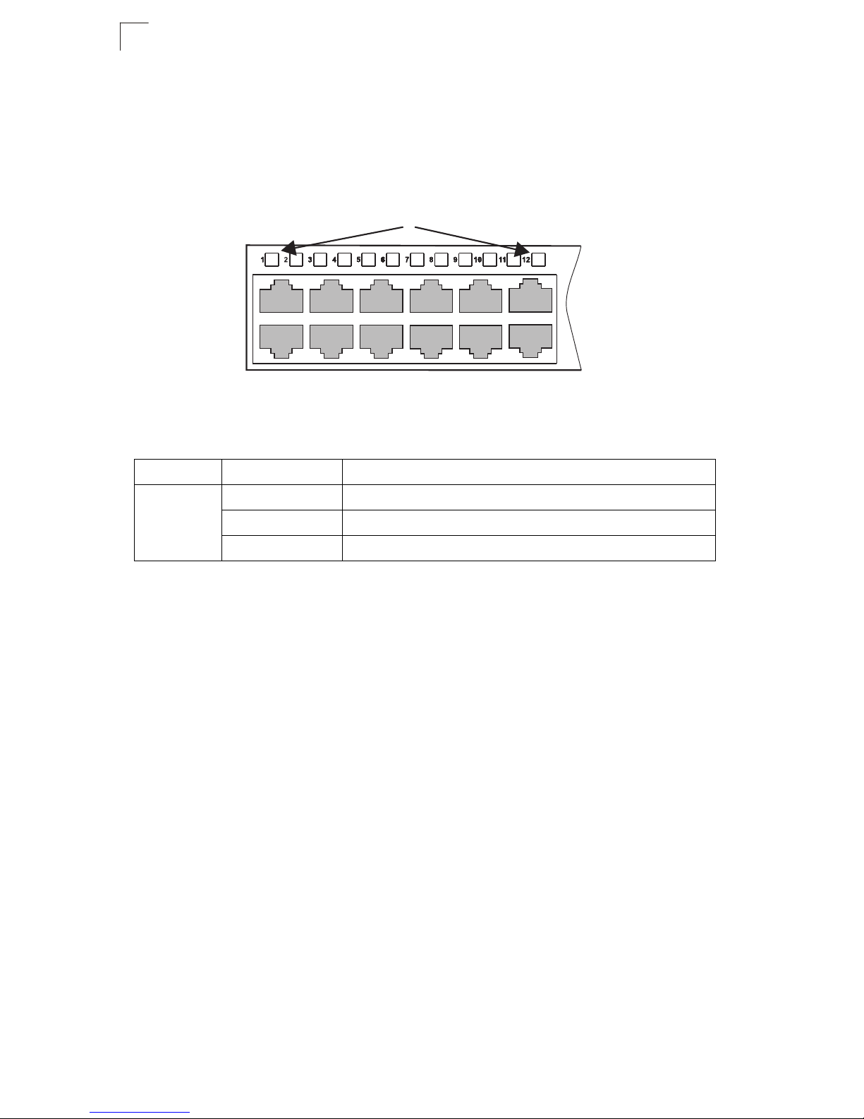
Port and System Status LEDs
These switches include a display panel for key system and port indications that
simplify installation and network troubleshooting. The LEDs, which are located on
the front panel for easy viewing, are shown below and described in the following
tables.
PortStatus LEDs
Figure 1-3 Port LEDs
Table 1-1 Port Status LEDs
LED Condition Status
Link/Activity On/Flashing Amber Port has a valid link at 10 or 100 Mbps. Flashing indicates activity.
On/Flashing Green Port has a valid link at 1000 Mbps. Flashing indicates activity.
Off There is no traffic passing through the port.
1-4
 Loading...