

Page 1

TRS 05
www.hirschmann.com
OPERATOR’S / SERVICE MANUAL
P/N 031-300-190-188 Revision B 08/30/2005
Page 2

Page 3
Operator’s/Installation/Service Manual TRS 05
NOTICE
Hirschmann makes no warranty of any kind with regard to this material, including, but not limited to,
the implied warranties of merchantability and/or its fitness for a particular purpose.
Hirschmann will not be liable for errors contained in this manual or for incidental or consequential
damages in connection with the furnishing, performance, or use of this manual. This document
contains proprietary information, which is protected by copyright, and all rights are reserved.
No part of this document may be photocopied, reproduced, or translated to another language without
the prior written consent of Hirschmann.
Hirschmann reserves proprietary rights to all drawings, photos and the data contained therein. The
drawings, photos and data are confidential and cannot be used or reproduced without the written
consent of Hirschmann. The drawings and/or photos are subject to technical modification without prior
notice.
All information in this document is subject to change without notice.
MANUAL REVISIONS
REV DATE NAME DESCRIPTION
- 03/15/05 CSH ECN 05-056
A 06/17/05 SB ECN 05-109
B 08/30/05 CSH/SB ECN 05-152
© 2005 Hirschmann, Chambersburg, PA 17201, USA
© Hirschmann TRS 05 REV B 08/30/2005 190188_B
Page 4

Page 5

General Information
5
TABLE OF CONTENTS
1
GENERAL INFORMATION ............................................................................................................ 1
2 WARNINGS .................................................................................................................................... 1
3 FEATURES..................................................................................................................................... 2
4 SYSTEM DESCRIPTION................................................................................................................ 2
4.1 Receiver Module.......................................................................................................................... 2
4.1.1 LEDs .....................................................................................................................................................3
4.1.2 Control Identification .............................................................................................................................3
5 OPERATION................................................................................................................................... 4
5.1 Receiver ...................................................................................................................................... 4
5.2 Transmitter .................................................................................................................................. 5
5.2.1 Load Cell...............................................................................................................................................5
5.2.2 Two-block Switch..................................................................................................................................5
5.3 Repeater...................................................................................................................................... 5
6 COMPONENT INSTALLATION ..................................................................................................... 6
6.1 Receiver ...................................................................................................................................... 6
6.2 Repeater...................................................................................................................................... 7
6.3 Central Unit Installation ............................................................................................................... 7
6.3.1 TRS 05 Installation on the DS350 modular system central unit...........................................................7
6.3.2 TRS 05 Installation on the DS350 standard system central unit..........................................................9
6.4 TRS 05 Setup overview............................................................................................................. 11
6.5 Sensor Output Setup ................................................................................................................. 12
6.5.1 Hardware ............................................................................................................................................12
6.5.2 Software..............................................................................................................................................12
7 TRS 05 SENSOR INSTALLATION .............................................................................................. 13
7.1 Install Sensor / Transmitter........................................................................................................ 13
7.2 Uninstall Sensor / Transmitter ................................................................................................... 13
8 LOAD CELL INSTALLATION ...................................................................................................... 14
9 LOAD SENSOR CALIBRATION .................................................................................................. 14
9.1 Load Sensor Zero point ............................................................................................................. 15
9.1.1 Additional Zero Point Adjustment for the DS350G standard system. ................................................16
9.2 Load Sensor gain Adjustment to a 70% permissible load ......................................................... 17
9.2.1 Accuracy and Test Requirements ......................................................................................................17
10 SERVICE AND TROUBLESHOOTING ........................................................................................ 18
10.1 Service....................................................................................................................................... 18
10.2 Troubleshooting......................................................................................................................... 19
10.2.1 Receiver..............................................................................................................................................19
10.2.2 Repeater.............................................................................................................................................20
10.3 Troubleshooting Moisture .......................................................................................................... 20
11 MAINTENANCE............................................................................................................................ 21
11.1 Battery Replacement ................................................................................................................. 21
12 SPARE PART NUMBERS............................................................................................................ 22
© Hirschmann TRS 05 REV B 08/30/2005 190188_B
Page 6

Page 7
General Information
1
1 GENERAL INFORMATION
The PAT TRS 05 system interface has been designed to use radio communication for load sensors.
The TRS 05 receives a radio signal from a transmitter sensor and converts a signal as a replacement
for the existing hardwired sensor.
Review system operator’s manual for system description and operation. All system functions and error
codes will remain the same for the DS350 system.
This manual will describe the operation, sensors setup and calibration, and additional troubleshooting
points for the TRS 05.
2 WARNINGS
Review system operator’s manual for system warnings.
The responsibility for the safe operation of the crane remains with the crane operator who must ensure
that all warnings and instructions supplied are fully understood and observed.
Prior to operating the crane, the operator must carefully and thoroughly read and understand the
information in this manual and the system manual to ensure that the operation and limitations of the
system and the crane are known.
The system can only work correctly, if all sensors/transmitters have been properly set. For
correct setup, the operator has correctly complete all procedures in this manual, the system
manual, and the setup procedure in accordance with the real rigging state of the crane. To
prevent material damage and serious or even fatal accidents, the correct adjustment of the
system has to be ensured before starting the crane operation.
Always refer to operational instructions and load charts provided by the crane manufacturer
for specific crane operation and load limits.
© Hirschmann TRS 05 REV B 08/30/2005 190188_B
Page 8
Operator’s/Installation/Service Manual TRS 05
2
3 FEATURES
The PAT TRS 05 has the following features:
• Can be hardwired to most PAT systems, and certain crane systems.
• Wireless operation of 4 sensors.
• Minimum of 500 feet LOS.
• Easily and clearly shows the operator required information for the radio sensor.
o Power LED (red)
o Link condition LED (green), LED on sensor installed and linked, LED flashing installed
but link or communication has been lost, and LED off sensor not installed.
o Low battery indication LED (yellow)
o Warning of Error LED (red)
4 SYSTEM DESCRIPTION
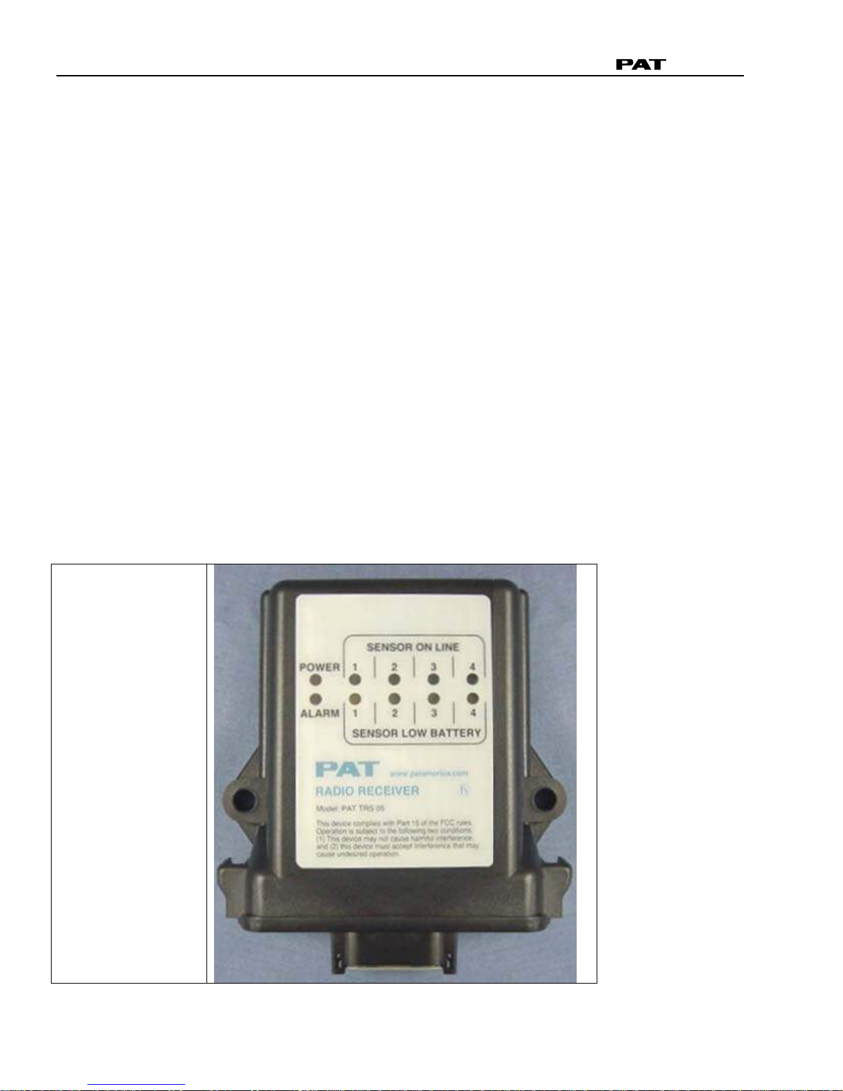
4.1 RECEIVER MODULE
The receiver module has the following functions:
• Visual indication of receiver power, radio links (sensor on line), sensors low battery, and alarm
conditions.
• Installs/uninstalls a sensor
• Allows a zero point and output adjustment of a load sensor.
Red Power LED
Red Alarm LED
Sensor On Line
Green LED 1
Green LED 2
Green LED 3
Green LED 4
Sensor Low Battery
Yellow LED 1
Yellow LED 2
Yellow LED 3
Yellow LED 4
© Hirschmann TRS 05 REV B 08/30/2005 190188_B
Page 9
System Description
4.1.1 LEDs
Red Power LED Power is applied to the circuit board.
Red alarm LED An installed sensor is indicating an alarm, or communication as been
lost to an installed sensor.
Green LED 1 ON Sensor on channel #1 is installed and communicating correctly.
Green LED 1 FLASHING Sensor #1 is not communicating correctly.
Green LED 1 OFF No sensor is installed on channel #1.
Yellow LED 1 ON Sensor #1 batteries are low and need replaced. Note that the sensor
is still operating correctly.
Green LED 2 ON Sensor #2 is installed and communicating correctly.
Green LED 2 FLASHING Sensor #2 is not communicating correctly.
Green LED 2 OFF No sensor is installed on channel #2.
Yellow LED 2 ON Sensor #2 batteries are low and need replaced. Note that the sensor
is still operating correctly.
Green LED 3 ON Sensor #3 is installed and communicating correctly.
Green LED 3 FLASHING Sensor #3 is not communicating correctly.
Green LED 3 OFF No sensor is installed on channel #3.
Yellow LED 3 ON Sensor #3 batteries are low and need replaced. Note that the sensor
is still operating correctly.
Green LED 4 ON Sensor #4 is installed and communicating correctly.
Green LED 4 FLASHING Sensor #4 is not communicating correctly.
Green LED 4 OFF No sensor is installed on channel #4.
Yellow LED 4 ON Sensor #4 batteries are low and need replaced. Note that the sensor
is still operating correctly.
Green Heartbeat LED This will flash during normal operation. If it is a solid or off, the
receiver has a software error or the board has a component failure.
3
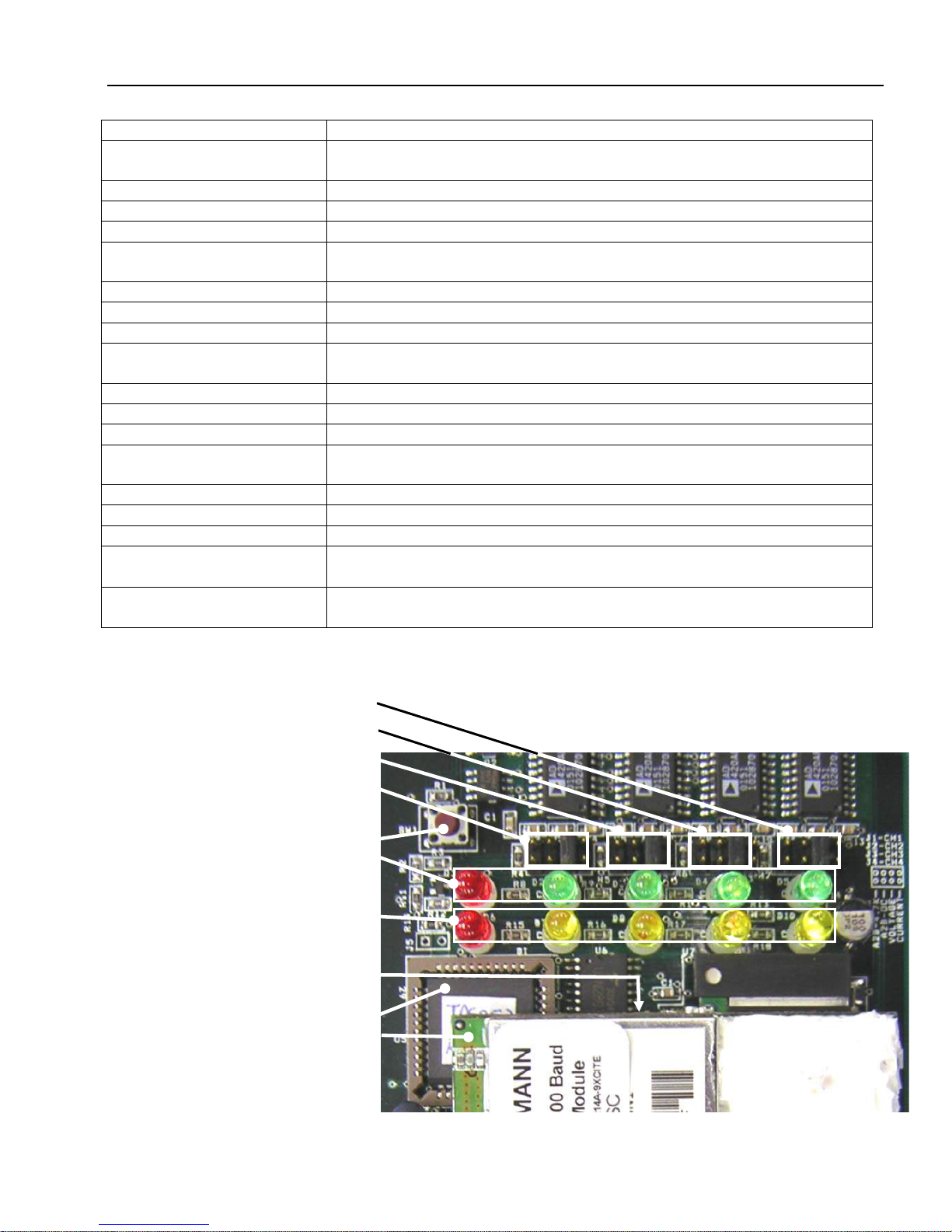
4.1.2 Control Identification
Sensor/Channel #1 output jumper J4
Sensor/Channel #2 output jumper J3
Sensor #3/Channel #2 output jumper J2
Sensor #4/Channel #2 output jumper J1
ID button
power (red), sensor on-line 1-4 left to
right (green)
LEDS
1-4 left to right (yellow)
LEDS Green Heartbeat LED (located just
under radio module)
software chip
radio module 031-300-300-024
© Hirschmann TRS 05 REV B 08/30/2005 190188_B
Page 10

Operator’s/Installation/Service Manual TRS 05
4
Heartbeat LED: When blinking, this small surface board mounted green LED indicates the system is
operation properly.
ID button: The red ID button, located below the software chip on the receiver board, is used to setup
the sensor transmitter to the receiver.
5 OPERATION
5.1 RECEIVER
Upon switching on crane ignition switch, the system starts with an automatic test of the receiver board,
LEDs and electronic components. The red power LED should be on and the green LEDs that sensors
have been linked to should also be on.
If an alarm condition exists investigate and clear the condition before operation and using the system.
During the normal operation of the system, the POWER and SENSOR ON LINE (if linked to a sensor)
LEDs should be on.
POWER LED
The POWER LED shows that the receiver is getting power from the crane. The receiver is on any time
the crane is operating and supplying power to the system.
SENSOR ON LINE LED
The SENSOR ON LINE LED indicates the status of communication of the transmitter(s). During
normal operation of the system, the LED will be on. The LED will flash if communication or
transmission between the sensor transmitter and the receiver is interrupted or lost. The system should
not be operated if the SENSOR ON LINE LED is flashing. If the LED is off no sensor is linked to this
channel.
LOW BATTERY LED
The low battery indicator will light indicating that you have a limited time to operate before the sensor
battery life ends. When the battery level is to the point that it is too low to operate, the system will stop
functioning. Use any off-the-shelf alkaline C-cells; Duracell, Eveready, etc.
ALARM LED
This LED will light simultaneously with the engaging of the lock out solenoids (if installed).
Test the electronics
Cycle the power to the system, each LED on the receiver will light for 2 seconds when the system is
powered. All of the indicator lights must come on or the system is not functioning properly. If any light
does not function, do not use the system until it has been repaired.
Refer to receiver operating manual for pre-operational inspection.
If a green sensor on line LED starts to flash, this means a sensor is installed and the communication
link has been lost. When communication has been lost to a load cell, the receiver will output the
maximum voltage signal for the output sensor (9VDC).
If a low battery LED is on, replace the batteries in the linked transmitter, refer to Battery Replacement
The TRS 05 setup/calibration procedure allows the operator to input the type of sensors being used,
and adjust the zero point and output adjustment of a load sensor. The operator must complete the
setup procedure for each sensor.
.
© Hirschmann TRS 05 REV B 08/30/2005 190188_B
Page 11

Operation
5
5.2 TRANSMITTER
The transmitter has an LED that will flash when a signal is transmitted to the receiver. Our system
transmits an OK signal every two seconds via three separate channels. This is to ensure accurate and
consistent reception of data and to reduce the possibility of unnoticed failure. The separate channels
greatly reduce the probability of failure due to external interferences. The receiver cycles through the
three channels, when software logic and/or lost signal, system will indicate a communication error.
5.2.1 Load Cell
The load cell transmits once every 1 to 2 seconds when in standby, and 2 times a second when the
load changes. It will continue at 2 times a second for less than a 1 minute before dropping back to one
transmission every 1 to 2 seconds. There is no time it goes to sleep.
Note: To extend battery life, remove batteries from transmitter(s) if load cell(s) will not be used for
extended periods of time. Reinstalling batteries into the transmitter will not require a set up.
NOTE: If the load cell is installed or reinstalled it will require
5.2.2 Two-block Switch
The PAT radio Anti-two Block (A2B) system works to prevent a two block condition using a weight and
switch. During normal operation the weight closes the A2B switch. The transmitter has an LED that
flashes approximately every 2 seconds when the switch is transmitting. If the weight is lifted and the
switch opens, the transmitter immediately (<100milliseconds) sends a two-block signal condition to the
receiver to be displayed on the console and lockout the crane movements (if connected to solenoid).
The LED will flash rapidly during a two-block condition and will stop flashing after 15 seconds when
the switch goes into sleep mode. While in sleep mode, the receiver will stay in a two-block or
communication loss condition. Sleep mode increases battery life by reducing the number of radio
transmissions. To wake the switch, simply close the switch by lowering the weight.
5.3 REPEATER
The purpose of the repeater is to reduce the possibility of a communication loss error by receiving the
load cell transmitted ID code and re-transmitting the same ID code out to the TRS 05. To do this, the
repeater is positioned at the boom tip, up the hoist rope from the load cell and up the boom from the
TRS 05. If the load cell does not have a direct line of sight or blocked by a wall/structure from the TRS
05 then there is less chance of the signal absorption/interference.
The repeater is setup from the factory to repeat signals from the load cells to the TRS 05 receiver.
TRS 05 can receive both transmissions (load cell and repeater) and output the load signal to the
system computer.
After switching power on to the repeater from the crane ignition switch, the system starts with an
automatic test of the repeater board, LEDs, and electronic components. The red power LED should be
on and other red LED blinks when the repeater is transmitting a signal.
© Hirschmann TRS 05 REV B 08/30/2005 190188_B
Page 12

Operator’s/Installation/Service Manual TRS 05
6
6 COMPONENT INSTALLATION
6.1 RECEIVER
The TRS 05 receiver module should be mounted so the operator can view the LED’s.
Securely attach the receiver onto a solid surface using the mounting holes.
SENSOR ON LINE
2
POWER
ALARM
1
1
SENSOR LOW BATTERY
2 3
3
4
4
Model: PAT TRS 05
This device complies with Part 15 of the FCC rules.
Operation is subject to the following two cond itions:
(1) This device may not cause harm ful interference,
and (2) this device must accept interference that may
cause undesired operation.
Power cable connections are show above.
© Hirschmann TRS 05 REV B 08/30/2005 190188_B
Page 13

Component Installation
7
6.2 REPEATER
The repeater module is mounted on the boom tip in line of sight to the receiver and the load cell. The
main purpose of the repeater is to receive and transmit the load cell ID code of the load cell during
operation. If the load cell line of sight is obstructed by a barrier (i.e. wall or building), the repeater
should prevent and signal loss.
Power cable connections: PIN 1 - +UB (9 to 30VDC), PIN 2 - GND
6.3 CENTRAL UNIT INSTALLATION
The power supply will be from 10- 30 volt DC. The signal output of the TRS 05 is dependent on the
placement of red bridges installed on the channel jumpers: 1 (for signal #1), 2 (signal #2), 3(signal #3),
and 4(signal #4). Each jumper has 4 bridge positions as follows:
1-2 voltage output 0..5V (required for the standard DS350 system)
3-4 amperage output 4..20mA (required for the modular DS350 system)
5-6 digital output
7-8 A2B switch output
6.3.1 TRS 05 Installation on the DS350 modular system central unit.
Breather
Element
1. Remove breather element, use a M21
wrench to hold the PG11 nut inside the
central unit.
2. Insert PG11 strain relief and tighten nut.
3. Insert cable as shown, so the shield will
ground on the strain relief cone. There
should be about 12 inches of cable inside
the central unit to make the proper
connections.
4. Connect to the central unit as shown below.
Refer to system wiring below
© Hirschmann TRS 05 REV B 08/30/2005 190188_B
Page 14

Operator’s/Installation/Service Manual TRS 05
8
Wiring information:
Power: the TRS 05 wires on X1:1 and X1:2 will need to be added to the existing wiring. Do not
remove the existing wire on these terminals.
Radio Load Cell wires on signal sensor 1 and 2: Remove the existing wires from terminal X1:25,
X1:36, X1:22, and X1:24 and add the TRS 05 wire as shown.
Hardwired Anti Two-Block Switch: If the hardwired A2B switch is being used; do NOT remove the
existing wires from X1:31 and X1:32. Do NOT wire # 7 and 8 from the TRS 05.
Radio Anti Two-Block Switch: If one or two radio A2B switch(es) are being used; remove the
existing wires from X1:31 and X1:32 and add the TRS 05 wire as shown. The second switch on signal
sensor 4 does not need to be wired. The TRS 05 software recognizes an A2B switch is connected to
signal sensor channel 3 and 4; therefore, if either switch is opened the signal is sent to the central unit.
© Hirschmann TRS 05 REV B 08/30/2005 190188_B
Page 15

Component Installation
6.3.2 TRS 05 Installation on the DS350 standard system central unit.
Metal shaving inside the central unit could cause a short or damage electrical components inside the
central unit. Use some type of protective plastic cover to shield the board from metal shavings, drill a
23/32” (0.718”) hole in the central unit housing in the location shown. Clean all metal shavings from
the central unit. Insert PG11 strain relief and tighten nut. Insert cable in the strain relief as shown,
leaving about 12” of wire in the central unit. The shield will ground on the strain relief cone and strain
relief will be tightened around the red/white insert.
9
© Hirschmann TRS 05 REV B 08/30/2005 190188_B
Page 16

Operator’s/Installation/Service Manual TRS 05
10
Wiring information:
Power: the TRS 05 wires on X1:2 and X1:3 will need to be added to the existing wiring. Do not
remove the existing wire on these terminals.
Radio Load Cell wires on signal sensor 1 and 2: Remove the existing wires from terminal X1:34,
X1:33, X1:24, and X1:23 and add the TRS 05 wire as shown.
Hardwired Anti Two-Block Switch: If the hardwired A2B switch is being used; do NOT remove the
existing wires from X1:39 and X1:40. Do NOT wire # 7 and 8 from the TRS 05.
Radio Anti Two-Block Switch: If one or two radio A2B switch(es) are being used; remove the
existing wires from X1:39 and X1:40 and add the TRS 05 wire as shown. The second switch on signal
sensor 4 does not need to be wired. The TRS 05 software recognizes an A2B switch is connected to
signal sensor channel 3 and 4; therefore, if either switch is opened the signal is sent to the central unit.
© Hirschmann TRS 05 REV B 08/30/2005 190188_B
Page 17

Component Installation
6.4 TRS 05 SETUP OVERVIEW
This section is a basic overview for the following Sections (TRS 05 Sensor Output Setup
Sensor Calibration). Press and hold ID button, release the button at the desired indication (or the
number seconds) defined in the following table. The following table can be use as a quick reference
guide when setting up the sensors on the TRS 05 and calibrating the load cell.
NOTE: If an incorrect menu is activated or the button is released accidentally, simply cycle the power
and start over.
Indication
Menu Selection Release ID Button Indication
Starts (Sec)
Install/setup sensor on channel 1 blinking green LED 1 3 6
Install/setup sensor on channel 2 blinking green LED 2 6 9
Install/setup sensor on channel 3 blinking green LED 3 9 12
Install/setup sensor on channel 4 blinking green LED 4 12 15
Uninstall a sensor on channel 1 solid LED 1 16 19
Uninstall a sensor on channel 2 solid LED 2 19 22
Uninstall a sensor on channel 3 solid LED 3 22 25
Uninstall a sensor on channel 4 solid LED 4 25 28
Set all the analog outputs for voltage 0-5V All 4 green LEDs blinking 29 32
Set all the analog outputs for 4..20ma All 4 green LEDs solid 33 36
Set all the analog outputs for voltage 1-9V All 4 yellow LEDs blinking 37 40
Set all the analog outputs for voltage 0-9V All 4 yellow LEDs solid 40 43
Calibrate load/angle sensor on channel 1 blinking yellow & green LEDs 1 43 46
Calibrate load/angle sensor on channel 2 blinking yellow & green LEDs 2 46 49
Calibrate load/angle sensor on channel 3 blinking yellow & green LEDs 3 50 53
Calibrate load/angle sensor on channel 4 blinking yellow & green LEDs 4 53 56
Service information on channel 1 blinking yellow LED 1 56 59
Service information on channel 2 blinking yellow LED 2 59 63
Service information on channel 3 blinking yellow LED 3 63 66
Service information on channel 4 blinking yellow LED 4 67
Exit/No action LEDs off no 71
and Load
Indication
Ends (Sec)
70
11
power (red), sensor link 1-4 left to right (green),
indication of load adjustment (up red LED
lit/down red LED off)
1-4 left to right (yellow)
LEDS Green Heartbeat LED
(located just under radio module)
radio module 031-300-300-024
© Hirschmann TRS 05 REV B 08/30/2005 190188_B
ID button
LEDS
software chip
Page 18

Operator’s/Installation/Service Manual TRS 05
12
6.5 SENSOR OUTPUT SETUP
The sensor output is setup for the hardware (bridge place on jumpers 1 & 2, as shown below) for the
load cells and software (use the ID button software output). If the hardware and software do not match
an error will occur.
6.5.1 Hardware
Install the bridge in the in the correct position; modular system – current or standard system – voltage
on jumpers 1 and 2, as show above. If a sensor is not installed, the bridges and jumpers will not effect
the operation of the unit.
A2B 4.7K position
Voltage position
Voltage position
ID Button
Standard CU
Standard CU
Current position
Current position
Modular CU
Modular CU
6.5.2 Software
Setup the software for the output of the TRS 05:
Standard System – voltage: Hold the ID button for about 29-32 seconds until all 4 green LEDs are
blinking and released ID button to set all the analog outputs for 0-5VDC voltage.
Modular System – current: Hold the ID button for about 33 36 seconds until all 4 green LEDs are
solid and released ID button to set all the analog outputs for 4...20mA current.
© Hirschmann TRS 05 REV B 08/30/2005 190188_B
Page 19

TRS 05 Sensor installation
13
7 TRS 05 SENSOR INSTALLATION
7.1 INSTALL SENSOR / TRANSMITTER
Setup the sensors on the 4 channels with the sensor as described below and mark the sensors, i.e.
CH1, MAIN, or LOAD 1. Note: The following list corresponds with the installation wiring in this manual.
Tip: bring the sensor close to the TRS 05 receiver/cab, not necessary but will simplify the procedure.
Remove the battery covers from the sensors to be installed.
Main load cell - channel 1; Press and hold the ID button for 3-6 seconds until the 1
begin blinking and release the ID button. The receiver begins to search for a transmitter ID code. On
the load sensor/transmitter, remove the card from the batteries or remove two batteries for 10 seconds
and replace them. In less than 10 seconds, the 1
st
green LED will become solid when the transmitter is
linked.
Auxiliary load cell - channel 2; Press and hold the ID button for 6-9 seconds until the 2
LED’s will begin blinking and release the ID button. The receiver begins to search for a transmitter ID
code. On the load sensor/transmitter, remove the card from the batteries or remove two batteries for
10 seconds and replace them. In less than 10 seconds, the 2
nd
green LED will become solid when the
transmitter is linked.
Main A2B switch - channel 3 (If included as system option); Press and hold the ID button for 9-12
seconds until the 3
rd
green LED’s will begin blinking and release the ID button. The receiver begins to
search for a transmitter ID code. On the A2B switch/transmitter, remove the card from the batteries or
remove two batteries for 10 seconds and replace them. In less than 10 seconds, the 3
become solid when the transmitter is linked.
Auxiliary A2B switch - channel 4 (If included as system option); Press and hold the ID button for
12-15 seconds until the 4
th
green LED’s will begin blinking and release the ID button. The receiver
begins to search for a transmitter ID code. On the A2B switch/transmitter, remove the card from the
batteries or remove two batteries for 10 seconds and replace them. In less than 10 seconds, the 4
green LED will become solid when the transmitter is linked.
NOTE: A new sensor or transmitter maybe install over an existing sensor on a channel, when
this occurs the previous link/ID code are removed from memory and the new one stored.
st
green LED’s will
nd
green
rd
green LED will
th
7.2 UNINSTALL SENSOR / TRANSMITTER
If a sensor is setup on the channel the LED will be ON, press and hold the ID button (16-28 seconds)
through the Install Sensor mode (blinking LEDs1-4) until the correct 1-4 LED is solid. When the correct
LED is solid, channel to be uninstalled, release the ID button. The sensor for the selected
channel/LED 1-4 will be uninstalled and the system will be in normal operating mode.
As the ID button is held (16-28 seconds) through the Install Sensor mode (blinking LEDs1-4) and
released at the solid LED, the following actions will occur:
Green LED 1 solid: Uninstall sensor 1.
Green LED 2 solid: Uninstall sensor 2.
Green LED 3 solid: Uninstall sensor 3.
Green LED 4 solid: Uninstall sensor 4.
© Hirschmann TRS 05 REV B 08/30/2005 190188_B
Page 20

Operator’s/Installation/Service Manual TRS 05
14
8 LOAD CELL INSTALLATION
NOTE: After installation the load cell will need to be zeroed with no force applied and adjusted
to a permissible heavy load.
The load cell and plates are installed at the dead end of the wire rope that is being used to lift the load.
The appropriate pins (length and diameter) for the type and size of socket, block, or ball must be used.
Ensure that the correct pin used is rated for the maximum line pull capacity and the side load plates
will be straight when attaching the dead end lug and the load cell. Install the side plates using the 21/4” pin so the pin head is on the antenna side. Ensure all safety pins are installed properly with
washers and bushing to fit the hole diameter and pin length.
9 LOAD SENSOR CALIBRATION
While the ID button is held or in the calibration process, the sensor outputs will not correctly indicate
the status of other installed sensors. Correct operation will return when the menu is exited or
calibration process is complete or system is powered off/on.
The load cell must be calibrated to ensure accuracy. The load sensor calibration is completed
complete the following steps:
1. Installing the load cell sensor (refer to 7.1 Install Sensor, if not complete)
2. Zero the load cell. The zero point adjustment will have an even affect across the entire range
(for example, 200 lb at both low and high loads).
3. Adjust the gain to a 70% permissible load. The gain adjustment will have only a small effect on
light loads, but a large effect on heavy loads.
Note: If an incorrect menu is activated or the button is released accidentally, simply cycle the power
and start over.
Note: When the system is in calibration mode, the RCL system NOT in operation; therefore, crane
operating guide line and load charts must be followed during calibration mode or other crane
operations.
NOTE: The unit will remain in main or auxiliary calibration mode until power is cycled off/on. After
completing the main load cell calibration, cycle power off/on and complete the auxiliary load
calibration.
Main load cell calibration: Press and hold the ID button for 43-46 seconds until the 1
green LED’s will begin blinking and release the ID button. The 1
st
yellow and green LED will become
st
yellow and
solid, showing the receiver is now in calibration mode for the main load cell on channel 1. Complete
sensor zero and gain adjustments in this section.
Auxiliary load cell calibration: Press and hold the ID button for 46-49 seconds until the 2
and green LED’s will begin blinking and release the ID button. The 2
nd
yellow and green LED will
nd
yellow
become solid, showing the receiver is now in calibration mode for the auxiliary load cell on channel 1.
Complete sensor zero and gain adjustments in this section.
© Hirschmann TRS 05 REV B 08/30/2005 190188_B
Page 21

Load Sensor Calibration
15
LED on increase load
LED off decrease load
Power on
Blinking yellow and green LED
calibrate channel/sensor #1
Blinking yellow and green LED
calibrate channel/sensor #2
Calibration mode is when the ID button is used to increase or decrease the displayed load to match
the actual load. If the alarm LED is on, when the ID button is press the displayed load will increased
until the button is released and the LED will go off. If the alarm LED is off, when the ID button is press
the displayed load will decreased until the button is released and the LED will come on.
Next the zero point and gain adjustments must be setup. The zero point must be a no load adjustment
and the gain adjustment is at least a 70% permissible load adjustment.
9.1 LOAD SENSOR ZERO POINT
To set the zero point of the load cell, place the load cell on the ground and ensure that no load on the
load cell, including any hook block, lengths of cable, etc. The software will only allow the load cell
zeroed when there is no load on the load cell. If there is a load on the load cell, the software will define
this as a gain adjustment.
What is the load displayed on the console? Does the load need to increased or deceased? The red
LED next to the yellow LED defines if the load will increase (RED LED “ON”) or decrease (RED LED
“OFF”) If the RED LED “ON”, pressing the ID will increase the load. When the ID button is released,
the RED LED goes “OFF”. Pressing the ID button will now decease the load. When the ID button is
released, the RED LED goes “ON”. Press the ID button until the displayed load is zero. For the
DS350G standard system, if the load can NOT be zeroed, the Additional Zero Point Adjustment for the
DS350G standard system must be complete.
The LEDs will not change after zero point has been set.
© Hirschmann TRS 05 REV B 08/30/2005 190188_B
Page 22

Operator’s/Installation/Service Manual TRS 05
M
U
7
3
M
M
3
4
4
3
2
7
9
8
16
9.1.1 Additional Zero Point Adjustment for the DS350G standard system.
(IF NECESSARY)
Adjust the Load Cell voltages on the main board.
MEMORY
BR-
X
RA
DATA EPRO
SYSTEM EPRO
CP
X
MP-13
X2
+.500
MP-12
MP-18
MP-
MP-11
MP-2
MP-1
MP-19
MP-15
X6
P3
MP-
X3
MP-5
P5P4
MP-6MP-
MP-
MP-
X1
1
• Adjust the main Load Cell zero point by placing your positive volt meter lead on MP 3
(measuring point 3) with your ground lead on MP 11. Turn the screw on potentiometer P3 so
the volt meter reads a value of 0.500 volts.
• Adjust the auxiliary Load Cell by placing your positive volt meter lead on MP 5 with your ground
lead on MP 11. Turn the screw on potentiometer P5 so the volt meter reads a value of 0.500
volts.
© Hirschmann TRS 05 REV B 08/30/2005 190188_B
Page 23

Load Sensor Calibration
17
9.2 LOAD SENSOR GAIN ADJUSTMENT TO A 70% PERMISSIBLE LOAD
To calibrate the gain of the load cell, a known load must be lifted. Check the load display by lifting a
load of known weight. The accuracy of the load indication shall be within the tolerance of SAE J376,
refer to complete SAE standard before testing. Refer to Accuracy and Test Requirements
before completing the calibration.
Ideally, the load should be as heavy as permissible given the load cell and crane configuration
chosen. When calculating the load on the load cell, it must be remembered to add the weight of any
headache ball, hook block, and rope used (depending on load cell location).
The software automatically switches from zero point to the gain adjustment when a load greater than
100lbs is applied to the load cell.
View the load reading on the display, and use the ID button to increase or decrease the reading as
necessary, in the same manner as was used to adjust the zero point.
When calibration is completed, re-check the zero point, a light load (hook block and rigging, a medium
load, and the load used for the gain adjustment.
If a new load cell is installed, or the load cell is uninstalled and re-installed, the calibrations must be
repeated. Installing a load cell causes the calibrations to revert to their default settings.
Exit the calibration mode by turning off the power supply to the TRS 05. Calibration settings are saved
to long term storage when the power turns on.
below
9.2.1 Accuracy and Test Requirements
Accuracy
The accuracy of the load indicating system is to be such that the indicated load is not less than 100%
of the actual load, nor more than 110% of the actual load. Where the system cannot meet the
accuracy criteria at the lower load range, conspicuous labeling or signaling is to be provided indicating
that these accuracy criteria cannot be met.
The weight of the load being lifted and all additional equipment such as blocks, slings, sensors, etc.;
also referred to as working load.
Test Requirements
System tests are to be conducted using an appropriate configured crane and specified load rating
chart.
For system calibration, three or more test radii or boom angle are to be employed to establish
compliance with the accuracy section above. Test loads shall be as near as is practical to minimum,
mean, and maximum values within the operating limits.
One of the following test methods or equivalent is to be used:
Known Weight
Test load to be applied by suspending known weights accurate to ± 1%. If the weights of all
additional equipment such as blocks, slings, sensors, etc., are included in the test load, the total
load is to be known to an accuracy of ± 1%.
© Hirschmann TRS 05 REV B 08/30/2005 190188_B
Page 24

Operator’s/Installation/Service Manual TRS 05
18
Fixed Anchor (Deadman)
Test load to be applied by hoisting against a fixed anchor or deadman equipped with a means for
measuring loads accurate to ± 1%. If the weights of all additional equipment such as blocks,
slings, sensors, etc., are included in the test load, the total load is to be known to an accuracy of ±
1%.
The system accuracy is to be determined from the following formula:
Indicated Load
x 100 = % of Load
Actual Load
10 SERVICE AND TROUBLESHOOTING
10.1 SERVICE
Daily maintenance of the system consists of inspecting:
1. The electrical wiring connecting the various parts of the system.
2. If electrical wiring is damaged, it shall be replaced immediately.
3. If the insulation is worn on the electrical wiring or antennas are damaged, these parts shall be
replaced.
4. A damaged or punctured housing or cover must be replaced immediately to prevent ingress of
water and damage to the internal circuitry.
Other than correcting the problems identified in the Malfunctions Table and replacing faulty
mechanical parts and cables, no other repairs shall be made.
© Hirschmann TRS 05 REV B 08/30/2005 190188_B
Page 25

Service and Troubleshooting
10.2 TROUBLESHOOTING
10.2.1 Receiver
After the onboard diagnostics have been performed, follow these guidelines
Problem Cause Solution
Power LED does
not light
Communication
error
Communication
error
Communication
error
Communication
error
Communication
error
Transmitter LED
does not flash
Transmitter LED
does not flash
No power to
receiver
Make sure the receiver is getting power from the crane.
Check wiring.
Ensure correct polarity of the power.
Open receiver and check green blinking status of LED.
Low battery Verify which sensor is causing the error by looking at
the communication error screen.
Replace batteries.
Faulty sensor Verify which sensor is causing the error by looking at
the communication error screen.
Verify that the LED on the sensor is blinking.
Poor reception Verify which sensor is causing the error by looking at
the communication error screen.
Verify that the LED on the sensor is blinking.
Verify that the sensor is line of sight to the receiver.
Sensor not
Install the sensor on the receiver. See adding sensors
installed.
Poor
communication
caused by
Remove potential interference sources from the area.
Mount the receiver in a different location.
interference.
Sensor is asleep. Change the status of the sensor.
Batteries dead. Replace the batteries.
19
© Hirschmann TRS 05 REV B 08/30/2005 190188_B
Page 26

Operator’s/Installation/Service Manual TRS 05
20
Receiver LED Definition
LED Sensor On Line 1 through 4 (Green) Indicates the status of the communication link
between sensor 1-4 transmitter and the receiver.
Failure of the communication link will cause the
Green LED to flash and the signal output will
change to the following condition:
• 4..20mA output will be 0mA
• 0..5V output will be 5VDC
Alarm LED (Red) Indicates a lock out condition. This LED will light
simultaneously with the engaging of the lock-out
solenoids (if installed).
LED Sensor Low Battery 1 through 4 (yellow) When the light goes off, it indicates that the battery
of the sensor 1-4 transmitter needs to be replaced.
10.2.2 Repeater
The red power LED should be on after switching on the repeater from the crane ignition switch, the
system starts with an automatic test of the repeater board, LEDs, and electronic components.
The other red LED blinks when the repeater is transmitting a signal. This can be compare to the load
cell transmitter when sitting side by side; the repeater module should transmit immediately after the
load cell.
10.3 TROUBLESHOOTING MOISTURE
The receiver and repeater contain electronic components and have an IP65 protection rating. These
electronic components cannot be designed to withstand exposure to moisture over a longer period of
time. If you find water or moisture inside any of the housings, the source for the water ingress has to
be detected and corrected to ensure proper operation.
There are two major possibilities for the occurrence of excessive moisture inside an enclosure:
1) Water ingress; caused by a cracked or broken housing or lid, or a defective gasket.
2) Condensation
This outline gives instructions for detecting the cause for excessive moisture by using simple
troubleshooting methods and how to prevent the moisture ingress from happening again.
© Hirschmann TRS 05 REV B 08/30/2005 190188_B
Page 27
Maintenance
21
11 MAINTENANCE
The only maintenance required is to change the batteries when required. Also, check the mounting
hardware daily to ensure that there is no damage. Replace any damaged parts before operating the
crane.
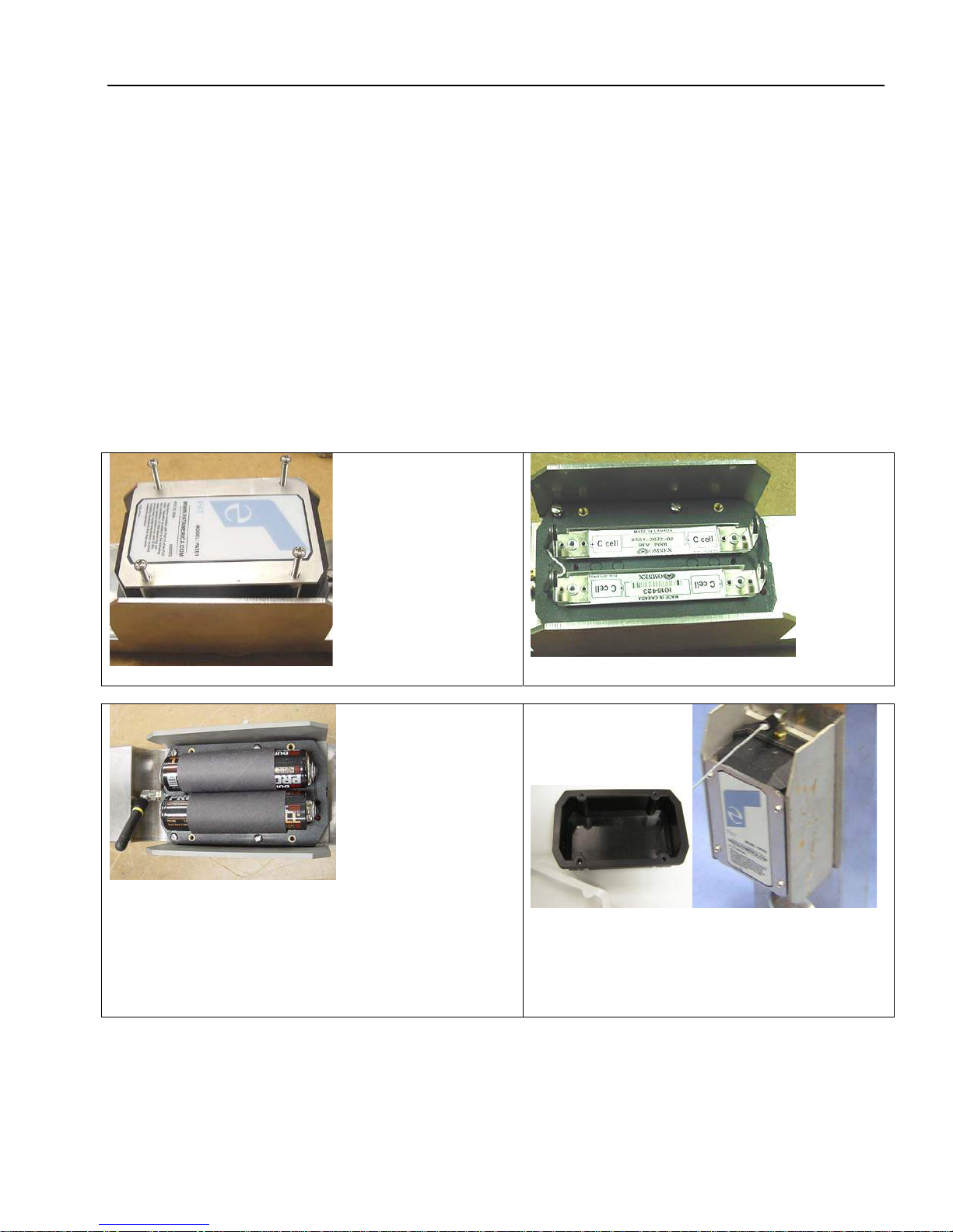
11.1 BATTERY REPLACEMENT
To replace the batteries, remove the 4 screws from the transmitter housing. During battery
replacement, use caution when opening the battery cover and transmitter to avoid damage to the
gasket causing moisture ingress which could corrode the batteries and terminals. Inspect the gasket
surface on the transmitter for nicks or other damages that may prevent the gasket from sealing. If it
appears to be damaged, a replacement gasket should be installed.
Install 4 fresh batteries into the proper location and direction as indicated on the battery holder.
Make sure that the cardboard tube is installed as shown.
Loosen 4 Screws
INSTALLED BATTERIES
Insert the batteries and cardboard sleeves. Ensure
the LED starts to flashing, when the batteries are first
install in a force transducer transmitter. LED comes
on for 1 second, off 1 sec and back on for 1 sec, then
begins to flash.
Battery Direction Label
Visually inspect the gasket and tighten the
battery cover in place with the 4 cover screws.
© Hirschmann TRS 05 REV B 08/30/2005 190188_B
Page 28

Operator’s/Installation/Service Manual TRS 05
22
12 SPARE PART NUMBERS
031-300-050-671
ANTENNA, 918 MHz FOR
TRS05ASSEMBLY 060-576
WHIP ELEMENT
031-300-050-672
ANTENNA, 918 MHz
MAGNETICBASE 13' long
wire
031-300-060-597 RADIO, RECEIVER, TRS05-2SPREAD
SPECTRUM W/NEG VOLT OUT
031-300-060-577 Cable Assembly 15’
© Hirschmann TRS 05 REV B 08/30/2005 190188_B
Page 29

Spare Part Numbers
031-300-060-596 TRS 05 repeater
031-300-050-688 ANTENNA, 918 MHz RCL 90°
23
031-300-060-709 CABLE ASSY, 15' 2 COND SS
20AWG W/12 SKT DEUTSCH AND 5 PIN CANNON
PLUG
031-300-060-609 SENSOR ASSY,
FORCE TRANS. 45KRADIO SPREAD
SPECTRUM REV.-
031-300-050-535 CONNECTOR, SMA RIGHT
ANGLE M/FREVERSE POLARITY
031-300-060-559 ANTENNA ASSY, 918
MHz WHIP FORLOAD CELL
© Hirschmann TRS 05 REV B 08/30/2005 190188_B
Page 30

Operator’s/Installation/Service Manual TRS 05
24
Antenna spare parts reiteration
031-300-050-672 ANTENNA, 918
MHz MAGNETICBASE 13ft long
wire
031-300-050-671 ANTENNA, 918 MHz
FOR TRS05ASSEMBLY 060-576 WHIP
ELEMENT
031-300-050-688 ANTENNA, 918 MHz
RCL 90°
031-300-060-559 ANTENNA ASSY, 918
MHz WHIP FORLOAD CELL
031-300-060-593
Radio A2B transmitter assembly
031-300-050-535 CONNECTOR, SMA RIGHT
ANGLE M/FREVERSE POLARITY
© Hirschmann TRS 05 REV B 08/30/2005 190188_B
Page 31

Spare Part Numbers
031-300-060-586 Radio A2B transmitter with antenna
031-300-050-688 (Antenna only)
25
031-300-050-536 031-300-050-763
Card board battery tube Neoprene rubber gasket
031-002-060-022
Radio A2B switch
© Hirschmann TRS 05 REV B 08/30/2005 190188_B
Page 32

Operator’s/Installation/Service Manual TRS 05
26
031-300-050-295
A2B Mounting stud
031-300-050-264
A2B mounting plate
031-300-050-272
Lynch pin
© Hirschmann TRS 05 REV B 08/30/2005 190188_B
 Loading...