

Hirschmann PAT 050-350-061-351, PAT 050-350-061-354, PAT 050-350-061-355 Replacement Instructions Manual
Page 1
050-350-061-351 050-350-061-354 050-350-061-355
CONSOLE, DS350 ON-DASH CONSOLE, DS350 ON-DASH CONSOLE, DS350 IN-DASH
GRAPHIC REPLACEMENT GRAPHIC REPLACEMENT GRAPHIC REPLACEMENT
FOR:
050-350-061-166 050-350-061-158 050-350-061-319
050-350-061-173 050-350-061-328
050-350-061-219 050-350-061-361
050-350-061-318
050-350-061-063 FOR: 050-350-061-062 FOR: 050-350-061-189
CONSOLE REPLACEMENT INSTRUCTIONS
Document Part Number 031-300-530-032
NOTICE
The information in this document is subject to change without notice.
Hirschmann ECS makes no warranty of any kind with regard to this material, including, but not limited to the
implied warranties of merchantability and fitness for a particular purpose.
Hirschmann ECS shall not be liable for errors contained in this manual or for incidental or consequential
damages in connection with the furnishing, performance, or use of this manual. This document contains
proprietary information that is protected by copyright.
All rights are reserved.
No part of this document may be photocopied, reproduced, or translated to another language without the prior
written consent of Hirschmann ECS.
© 2006 Hirschmann ECS 031-300-530-032 Revision F 03/28/06 0032_F53
Page 2

Console Replacement Instructions
TABLE OF CONTENTS
CONSOLE INSTALLATION ………………………………………………….. 2
050-350-061-351 / 050-350-061-354 Console Installation overview ……… 2
050-350-061-189 / 050-350-061-355 Console Installation overview ……… 3
CENTRAL UNIT, DS350GM (24 350 06 300x)……………………………… 4
System Software Installation Overview……………………………………….. 4
Procedure 1. Eprom Replacement ..………………………………………….. 4
Procedure 2. Strain Relief Installation ………………………………………. 5
Procedure 3. Console cable installation in central unit ……………………. 6
CENTRAL UNIT, DS350G (24 350 06 0700, 0701, 0721, 2766) …………. 7
System Software Replacement for DS350G ………………………………… 7
Serial Interface Installation ……………………………………………………. 8
Central Unit Preparation………………………………………………………… 9
Central Cable Assembly Installation …………………………………………. 9
Grounding of Inner Shield ……………………………………………………… 9
DS350G Central Unit Wiring (24 350 06 2766)………………………………. 10
DS350G Central Unit Wiring (24 350 06 0701, 0721)………………………..11
DS350G Central Unit Wiring (24 350 06 0700)………………………………. 12
CENTRAL UNIT, DS350G (24 350 06 2767)………………………………… 13
Serial Interface Installation………………………………………………………13
Central Unit Preparation…………………………………………………………14
Cable assembly installation…………………………………………………….. 14
Grounding of Inner Shield………………………………………………………. 14
DS350G Central Unit Wiring…………………………………………………….15
CENTRAL UNIT, DS350GM (24 350 06 3015)……………………………….16
Procedure 1. Strain Relief Installation…………………………………………16
Procedure 2. Console cable installation in central unit………………………17
REQUIRED TOOL LIST
1 - #1 PHILLIPS HEAD SCREWDRIVERS
1 – ¼” SLOTTED HEAD SCREWDRIVERS
1 – ADJUSTABLE WRENCH
1 – WIRE CUTTERS
1 – VICE GRIP PLIERS
1 – ROLL INSULATION TAPE
1 – NEEDLE NOSE PLIERS
1 – WIRE CRIMPING PLIERS
1 – UTILITY KNIFE
1 – EPROM PULLER
© 2006 Hirschmann ECS 031-300-530-032 Revision F 03/28/06 0032_F53
Page 1
Page 3
Console Replacement Instructions
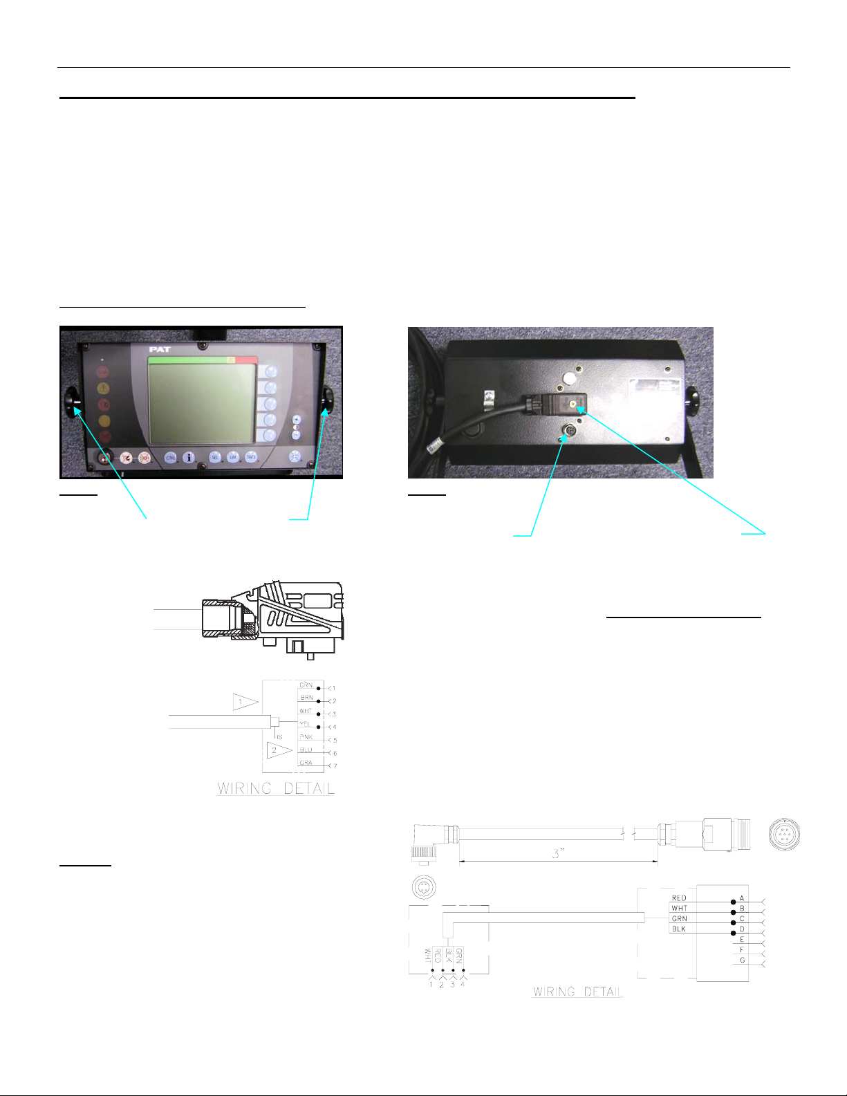
050-350-061-351 / 050-350-061-354 CONSOLE INSTALLATION OVERVIEW
1. Remove existing console at the adjustment knobs. (Fig. 1)
2. Install new console on the dash using the existing mounting bracket.
3. Connect and fix the connector on console cable assy 031-300-060-598 to the console. (Fig. 2)
4. Route console cable assy to the central unit following the same path as the existing console cable
assy.
5. Refer to appropriate Central Unit section for further installation instructions.
6. Cable Assembly 031-300-060-520 will be required for installation of the lightbar option currently
installed on the DS350GW horizontal and vertical consoles.
050-350-061-351 / 050-350-061-354
Fig. 1
Fig. 2
Adjustment knobs
Lightbar connection
Fig. 3
NOTE:
Cable Assembly 031-300-060-520 will be
required for installation of the lightbar option
currently installed on the DS350GW horizontal
and vertical consoles.
Secure with screw
WIRE COLOR CHART
BLU (BLUE)
BRN (BROWN)
GRA (GRAY)
GRN (GREEN)
PNK (PINK)
WHT (WHITE)
YEL (YELLOW)
© 2006 Hirschmann ECS 031-300-530-032 Revision F 03/28/06 0032_F53
Page 2
Page 4

Console Replacement Instructions
050-350-061-189 / 050-350-061-355 CONSOLE INSTALLATION OVERVIEW
1. Remove existing console, console wiring, and housing. Note: The existing wiring will be used to
wire the new console.
2. Install (2) console nut strips item 2
dash per Detail “B”.
3. Install new console with housing in tact. Secure to nut strips item 2
Detail “B”.
4. secure existing cable with clamp (part of console) per View C-C. Be sure the cable’s outer shield is
in contact with the clamp.
5. wire the 8-pole connector on the rear of the console per the wiring diagram. Ref. View C-C.
ITEM PART NUMBER QTY DESCRIPTION
1 050-350-061-355 1 CONSOLE, DS350 I N-DASH GRAPHICREPLACEMENT FOR DS350/1319
2 031-300-050-746 2 MOUNTING PLATE, CONSOLE NUTSTRIP
3 031-300-050-515 4 SCREW, #6-32 X 1/2, FH, PH
4 031-300-050-547 8 SCREW, #6-32 X 3/4 ALLEN HEADBLACK MACHINE SCREW
5 024-350-300-147 1 BOARD, SERIAL INTERFACE DS350/0147/VAR.
6 031-300-060-610 1 CABLE ASSY, 4 COND LT
using (4) screws item 3 through the existing countersunk holes in
with (8) screws item 4 per
© 2006 Hirschmann ECS 031-300-530-032 Revision F 03/28/06 0032_F53
Page 3
Page 5
Console Replacement Instructions
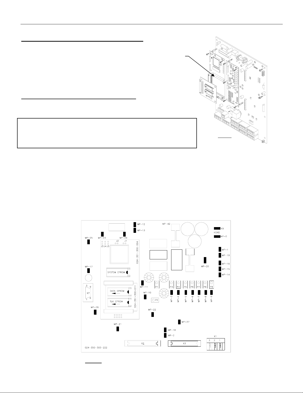
CENTRAL UNIT, DS350GM (24 350 06 300x)
System Software Installation Overview
1. Remove C.U. lid.
2. Remove system software and replace
with (GGMT V2.0) system software eprom. (Fig.4)
(For further eprom replacement instructions
see Procedure1 below.)
PROCEDURE 1. EPROM REPLACEMENT
2
S
Y
S
T
E
M
D
A
T
A
T
L
K
Remove cover, from central unit.
CAUTION: Before handling the EPROM, discharge any static
electricity from your body by touching a grounded point.
Fig. 4
The EPROM could be damaged by static electricity.
1. Refer to the drawing below for correct eprom locations. (Fig.4a)
2. Remove the old system eprom, from the main board. Be careful to pull the eprom out
without bending the legs.
NOTE: Ensure the notch is in the correct direction. Notch on eprom must match the notch on the
socket and markings on the board.
3. Place new eprom in the correct eprom socket as shown. Carefully align the new eprom legs
with the socket and push the eprom into place. Be careful not to bend any of the legs.
Fig. 4a
© 2006 Hirschmann ECS 031-300-530-032 Revision F 03/28/06 0032_F53
Page 4
Page 6

Console Replacement Instructions
PROCEDURE 2. STRAIN RELIEF INSTALLATION
Fig. 5
1. Remove existing cable, ferrite filter and strain relief from central unit. (Fig. 5)
2. Install the new PG13.5 RED/WHT strain relief using the existing PG13.5 nut, from the strain
relief just removed.
3. Reinstall ferrite filter. (Fig. 5a).
Note: Outer shield is grounded at strain relief insert.
Fig. 5a
© 2006 Hirschmann ECS 031-300-530-032 Revision F 03/28/06 0032_F53
Page 5
Page 7

Console Replacement Instructions
PROCEDURE 3. CONSOLE CABLE INSTALLATION IN CENTRAL UNIT
1. Ensure console is properly installed in cab.
2. Route console cable assembly (031-300-060-598) to the central unit following the same path as the
existing console cable assembly. Cut the console cable to the appropriate length.
3. Wire the console cable assembly in central unit referencing the diagram. (Fig. 6)
4. Install the C.U. lid. Reinstall and any grounding wires removed, then install the cover and tighten
screws, making sure the rubber gasket, is positioned correctly, to prevent any moisture from entering the
central unit.
Fig. 6
© 2006 Hirschmann ECS 031-300-530-032 Revision F 03/28/06 0032_F53
Page 6
Page 8

Console Replacement Instructions
CENTRAL UNIT, DS350G ( 24 350 06 0700, 24 350 06 0701, 24 350 06 0721, 24 350 06 2766)
SYSTEM SOFTWARE REPLACEMENT FOR DS350G
1. Remove cover, from central unit.
CAUTION: Before handling the EPROM, discharge any static electricity from your body by touching a
grounded point. The EPROM could be damaged by static electricity.
2. Remove the existing system and CPU eproms from the main board. (Fig. 7) Be careful to pull the
EPROM out, without bending the legs.
3. Install eprom module 024-350-300-172 into the CPU and system software sockets. (Fig. 7a)
Replace the CPU and new system software (MGWT) eprom into the eprom module.
NOTE: The notch on the EPROM and in the socket determines the correct orientation of the EPROM.
Refer to the drawing below for correct EPROM locations.
4. Carefully align the new EPROM legs with the socket and push the EPROM into place. Be careful not
to bend any of the legs.
Fig. 7
Fig. 7a
3,4
Fig. 7b
© 2006 Hirschmann ECS 031-300-530-032 Revision F 03/28/06 0032_F53
Page 7
Page 9

Console Replacement Instructions
Serial Interface installation
1. Locate position of installation. (Fig. 8)
2. Remove two screws and lock washers
from the main board. (Fig. 9)
3. Install two 4mm x 20mm standoffs where
the screws were removed. (Fig. 10)
4. Attach mounting rail 031-300-050-721 on top
of the standoffs using the screws and lock washers
removed from the main board. (Fig. 11)
5. Install (snap) serial interface board 024-350-300-147
on the mounting rail. (Fig. 11)
Fig. 8
4
5
Fig. 9
Fig. 10
Fig. 11
2
3
6. Wire cable assy 031-300-060-610 (crimp ferrule end) to terminal X1 on the serial interface board per
the electrical schematic. (Fig. 12 and 15, 15a)
7. Wire the other end of the cable (1/8” female terminal end) to the connection board per the electrical
schematic. (Fig. 12 and 15, 15a, 15b)
7
6
© 2006 Hirschmann ECS 031-300-530-032 Revision F 03/28/06 0032_F53
Fig. 12
Page 8
Page 10

Console Replacement Instructions
Central Unit Preparation
1. Remove existing console cable and strain relief from the central unit and install PG13.5 hole plug
using the existing nut. Remove existing PG11 hole plug. Install new PG11 strain relief using the
existing nut. (Fig. 13)
Fig. 13
Cable Assembly Installation (24 350 06 2766 only)
1. Attach inner shield to grounding clamp on the
connection board per diagram. (Fig. 14 and 14a)
2. Install 1/8” and ¼" female terminals on wire
ends and attach to connection board and diode
assy per electrical schematic. (Fig. 15)
3. Reinstall central unit lid and any grounding wires
that were removed.
Grounding of Inner Shield (24 350 06 2766 only)
Inner shield is grounded on connection board.
(Not required when replacing the 050-350-061-189 console). Do not remove
existing cable between console and central unit for installation of the
050-350-061-355 console.
1
Fig. 14
Cut inner shield back to approximately 1.2 inch. Then fold inner shield back to inner jacket, so the inner
shield is 0.6 inches in length.
Page 9
© 2006 Hirschmann ECS 031-300-530-032 Revision F 03/28/06 0032_F53
Fig. 14a
Page 11

Console Replacement Instructions
DS350G Central Unit Wiring (24 350 06 2700, 2766)
Fig. 15
© 2006 Hirschmann ECS 031-300-530-032 Revision F 03/28/06 0032_F53
Page 10
Page 12

Console Replacement Instructions
DS350G Central Unit Wiring (24 350 06 0701, 24 350 06 0721)
Fig. 15a
© 2006 Hirschmann ECS 031-300-530-032 Revision F 03/28/06 0032_F53
Page 11
Page 13

Console Replacement Instructions
DS350G Central Unit Wiring (24 350 06 0700)
Fig. 15b
ITEM PART NUMBER QTY DESCRIPTION
1 050-350-061-355 1 CONSOLE, DS350 IN-DASH GRAPHICREPLACEMENT FOR DS350/1319
2 031-300-050-746 2 MOUNTING PLATE, CONSOLE NUTSTRIP
3 031-300-050-515 4 SCREW, #6-32 X 1/2, FH, PH
4 031-300-050-547 8 SCREW, #6-32 X 3/4 ALLEN HEADBLACK MACHINE SCREW
5 024-350-300-147 1 BOARD, SERIAL INTERFACE DS350/0147/VAR.
6 031-300-060-610 1 CABLE ASSY, 4 COND LT
© 2006 Hirschmann ECS 031-300-530-032 Revision F 03/28/06 0032_F53
Page 12
Page 14

Console Replacement Instructions
CENTRAL UNIT, DS350GC (24 350 06 2767)
Serial Interface Installation
1. Locate position of installation. (Fig. 8)
2. Remove two screws and lock washers
from the main board. (Fig. 9)
3. Install two 4mm x 20mm standoffs where
the screw were removed. (Fig. 10)
4. Attach mounting rail 031-300-050-721 on top
of the standoffs using the screws and lock washers
removed from the main board. (Fig. 11)
5. Install (snap) serial interface board 024-350-300-147
on the mounting rail. (Fig. 11)
Fig. 9
2
6. Wire cable ass’y 031-300-060-610 (crimp ferrule end) to terminal X1 on the serial interface board per
the electrical schematic. (Fig. 12 and 16)
7. Wire the other end of the cable (1/8” female terminal end) to the connection board per the electrical
schematic. (Fig. 12 and 16)
Fig. 10
7
6
Fig. 8
3
4
Fig. 11
3
Fig. 12
© 2006 Hirschmann ECS 031-300-530-032 Revision F 03/28/06 0032_F53
Page 13
Page 15

Console Replacement Instructions
Central Unit Preparation
1. Remove existing console cable and strain relief from the central unit and install PG13.5 hole plug
using the existing nut. Remove existing PG11 hole plug. Install new PG11 strain relief using the
existing nut. (Fig. 13)
1
Fig. 13
Cable Assembly Installation
1. Attach inner shield to grounding clamp on the
connection board per diagram. (Fig. 14 and 14a)
2. Install 1/8” and ¼" female terminals on wire
ends and attach to connection board and diode
ass’y per electrical schematic. (Fig. 16)
3. Reinstall central unit lid and any grounding wires
that apply.
Grounding of Inner Shield
Inner shield is grounded on connection board.
Fig. 14
Cut inner shield back to approximately 1.2 inch. Then fold inner shield back to inner jacket, so the inner
shield is 0.6 inches in length.
Page 14
© 2006 Hirschmann ECS 031-300-530-032 Revision F 03/28/06 0032_F53
Fig. 14a
Page 16

Console Replacement Instructions
5
DS350G Central Unit Wiring (24 350 06 2767)
Fig. 16
© 2006 Hirschmann ECS 031-300-530-032 Revision F 03/28/06 0032_F53
Page 1
Page 17

Console Replacement Instructions
CENTRAL UNIT, DS350GM (24 350 06 3015)
PROCEDURE 1. STRAIN RELIEF INSTALLATION
Fig. 17
1. Remove cover from the central unit. Remove ground and heater wires as required.
2. Remove existing cable and strain relief grommet from the central unit. Do not remove the
strain relief. (Fig. 17)
3. Install the new strain relief grommet only, and install console cable. (Fig. 18).
Note: Outer shield is grounded at strain relief insert.
© 2006 Hirschmann ECS 031-300-530-032 Revision F 03/28/06 0032_F53
Fig. 18
Page 16
Page 18

Console Replacement Instructions
PROCEDURE 2. CONSOLE CABLE INSTALLATION IN CENTRAL UNIT
1. Ensure console is properly installed in cab.
2. Route console cable assembly (031-300-060-697) to the central unit following the same path as the
existing console cable assembly. Cut the console cable to the appropriate length.
3. Wire the console cable assembly in central unit referencing the diagram. (Fig. 19)
4. Install the C.U. lid. Reinstall and any grounding and heater wires removed, then install the cover and
tighten screws, making sure the rubber gasket, is positioned correctly, to prevent any moisture from
entering the central unit.
Fig. 19
© 2006 Hirschmann ECS 031-300-530-032 Revision F 03/28/06 0032_F53
Page 17
Page 19

 Loading...