

Page 1
Manual
PAL modulator 1 HU
version: 1. 2
print: March 96/BH_1760E
Hirschmann ü
Page 2

Index
Introduction
1 - 1
General Notes
. . . . . . . . . . . . . . . . . . . . . . . . . . . . . . . . . . . . . . . . . . . . . . . . . . . 1 - 2
Technical modifications . . . . . . . . . . . . . . . . . . . . . . . . . . . . . . . . . . . . . . . . . . . . . . . 1 - 2
Guarantee and Warranty . . . . . . . . . . . . . . . . . . . . . . . . . . . . . . . . . . . . . . . . . . . . . . 1 - 2
Co p y righ t . . . . . . . . . . . . . . . . . . . . . . . . . . . . . . . . . . . . . . . . . . . . . . . . . . . . . . . . . . 1 - 2
Explanation of the warning and note symbols
. . . . . . . . . . . . . . . . . . . 1 - 2
Operation
2 - 1
Fun ct i on al d es cr i pti on
. . . . . . . . . . . . . . . . . . . . . . . . . . . . . . . . . . . . . . . . . . . 2 - 2
General. . . . . . . . . . . . . . . . . . . . . . . . . . . . . . . . . . . . . . . . . . . . . . . . . . . . . . . . . . . . 2 - 2
Block diagram. . . . . . . . . . . . . . . . . . . . . . . . . . . . . . . . . . . . . . . . . . . . . . . . . . . . . . . 2 - 3
Video pro cessor VP 501/ 1 . . . . . . . . . . . . . . . . . . . . . . . . . . . . . . . . . . . . . . . . . . . . . 2 - 5
Vision/Sou nd m odulator BTM 501/ 1 . . . . . . . . . . . . . . . . . . . . . . . . . . . . . . . . . . . . . 2 - 7
Sound2 modulator T2M 501/ 1 . . . . . . . . . . . . . . . . . . . . . . . . . . . . . . . . . . . . . . . . . . 2 - 9
IF matching unit . . . . . . . . . . . . . . . . . . . . . . . . . . . . . . . . . . . . . . . . . . . . . . . . . . . . 2 - 10
Interfaces
. . . . . . . . . . . . . . . . . . . . . . . . . . . . . . . . . . . . . . . . . . . . . . . . . . . . . . . 2 - 11
Module f rontside . . . . . . . . . . . . . . . . . . . . . . . . . . . . . . . . . . . . . . . . . . . . . . . . . . . . 2 - 11
Module r ear side . . . . . . . . . . . . . . . . . . . . . . . . . . . . . . . . . . . . . . . . . . . . . . . . . . . . 2 - 12
Putti ng th e modu lator in to oper atio n
. . . . . . . . . . . . . . . . . . . . . . . . . . . . 2 - 1 3
Help with problems
. . . . . . . . . . . . . . . . . . . . . . . . . . . . . . . . . . . . . . . . . . . . . 2 - 1 4
Video pro cessor . . . . . . . . . . . . . . . . . . . . . . . . . . . . . . . . . . . . . . . . . . . . . . . . . . . . 2 - 14
Vision/sound modulator . . . . . . . . . . . . . . . . . . . . . . . . . . . . . . . . . . . . . . . . . . . . . . 2 - 14
Sound2 modulator . . . . . . . . . . . . . . . . . . . . . . . . . . . . . . . . . . . . . . . . . . . . . . . . . . 2 - 15
Index
Manual
0 - 2
PAL modulator 1 HU
ü
Page 3

Service
3 - 1
Warn ing N ote
. . . . . . . . . . . . . . . . . . . . . . . . . . . . . . . . . . . . . . . . . . . . . . . . . . . 3 - 2
Adjustments
. . . . . . . . . . . . . . . . . . . . . . . . . . . . . . . . . . . . . . . . . . . . . . . . . . . . . 3 - 2
Functional check
. . . . . . . . . . . . . . . . . . . . . . . . . . . . . . . . . . . . . . . . . . . . . . . . 3 - 2
Han dlin g
. . . . . . . . . . . . . . . . . . . . . . . . . . . . . . . . . . . . . . . . . . . . . . . . . . . . . . . . 3 - 2
Equipment
. . . . . . . . . . . . . . . . . . . . . . . . . . . . . . . . . . . . . . . . . . . . . . . . . . . . . . 3 - 3
Custom er Ser vic e
. . . . . . . . . . . . . . . . . . . . . . . . . . . . . . . . . . . . . . . . . . . . . . . 3 - 4
Data sh ee ts
4 - 1
Data sheet index
. . . . . . . . . . . . . . . . . . . . . . . . . . . . . . . . . . . . . . . . . . . . . . . . 4 - 2
Data sheet identi fication
. . . . . . . . . . . . . . . . . . . . . . . . . . . . . . . . . . . . . . . . 4 - 2
Index
Manual
ü
PAL modul ator 1 H U
0 - 3
Page 4

Index
Manual
0 - 4
PAL modulator 1 HU
ü
Page 5

Introduction
Introduction
Manual
ü
PAL modul ator 1 H U
1 - 1
Page 6

General Notes
CAUTIO N:
Keep the manual handy all the time.
Technical modifications
The information contained i n this manual is subject to change at any time.
Guarantee and Warranty
The Hirschmann Company assum es no liability whatsoever (liability for material
defects, legal warrant y, guarantee for marketability, violation of existing pat ent
rights) with the exception of the guarantees indicat ing in this manual.
Copyright
This manual covers informat ion protected by copyright. All rights are reserved.
No part of this manual may be photocopied, otherwise reproduced or translated
into another language without the prior writte n consent of Hirschmann.
Explanation of the warning and note sy mbols
WARNING:
Indicates that non compliance with the cautionar y
measures listed could result in personal injury or
equipment damage.
CAUT IO N:
Indicates that non compliance with the cautionar y
measures listed could result in equipment damage.
NOTE:
Comments giving usefu l tips and information on
practical app lication.
Int rod uction
Manual
1 - 2
PAL modulator 1 HU
ü
Page 7

Operation
Operation
Manual
ü
PAL modul ator 1 H U
2 - 1
Page 8

Functional description
General
The PAL modulator is used in headend systems. It processes a scrambled
video signal and supplies the following IF signals:
l
IF vision carrier
l
IF so und carrier 1 (IF SC 1)
l
IF so und carrier 2 (IF SC 2)
l
IF so und carrier 1+ 2 (IF SC1 +2)
It can be used for stereo/2sound and mono transmission.
The PAL modulator functional group consists of:
l
Assy video processor
l
Assy vision/s ound modulator
l
Assy sound2 modulator
l
IF mat ching unit
l
IF locking
l
AUX assy
l
Re mot e re cor d int erf ac e
l
Rear panel assy
l
Data processor
Arrangement All of t he terminals of t he m odul e ar e located on the back of t he main f r ame.
The monitoring outputs and the interface for the Data processor (PC monitoring) are located in front of it. Adj ustm ent ele ments f or t uning are on the f r ont
panel and inside the module. The IF matching unit and the power supply are attached to the rear side of the main frame.
Monito ring Check of the most important par am eters can be made vi a t he PC m onit oring
software. Therefor a Dataprocessor DP 501-1 is nessesary, witch handle the
data communication between t he PAL modulator and the PC.
The following signals are availabl e on the rear side of the main frame on
connector "S TATUS"
l
video si gnal on the vi deo main sync. input is present
l
summary fault
Operation
Manual
2 - 2
PAL modulator 1 HU
ü
Page 9
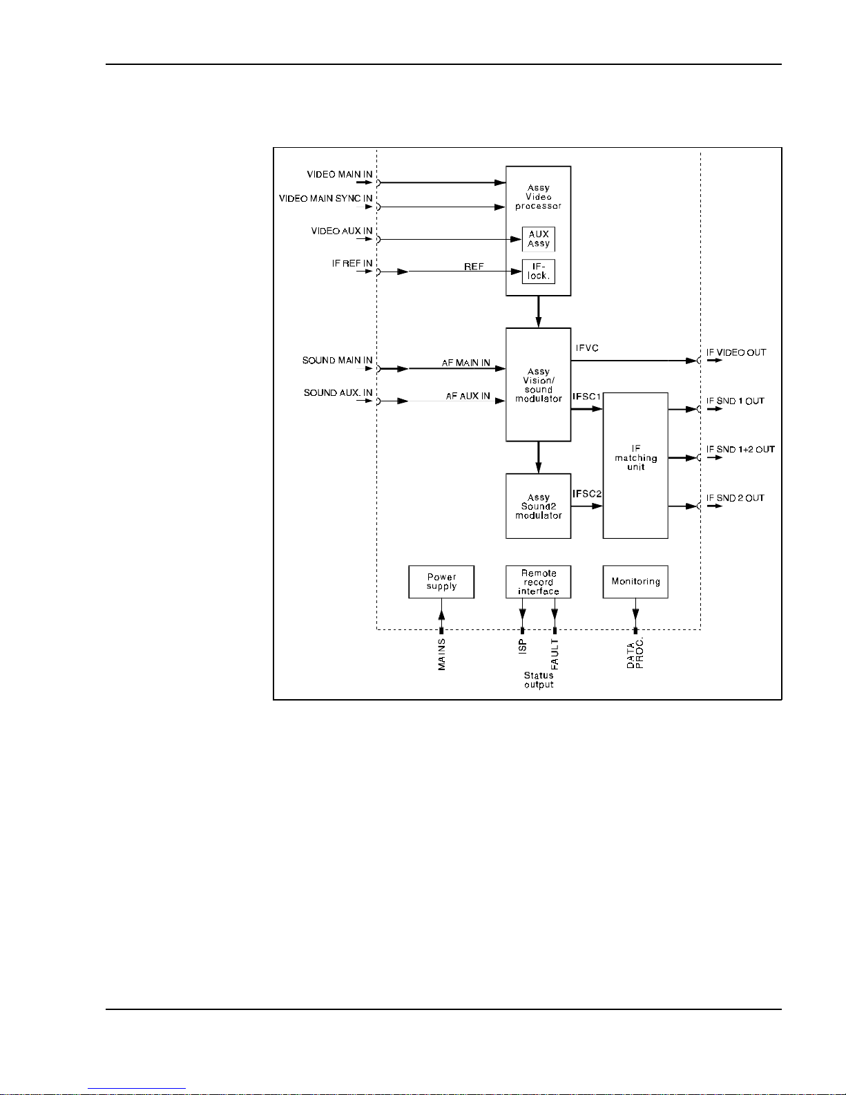
Block diagram
Block diagram of overall PAL modulator 1 HU
Oper ati on
Manual
ü
PAL modul ator 1 H U
2 - 3
Page 10

Schematic diagram of the video processor , vision sound modulator and sound2
modulator
Operation
Manual
2 - 4
PAL modulator 1 HU
ü
Page 11

Video processor VP 501/1
The video signal being fed in, it is precorrected in the video processor and fed
the vision/sound modulator.
Inputs
The video processor has the following inputs:
l
VIDEO MAIN IN: Scrambled main video input
l
VIDEO AUX I N: Substitute video input
l
VIDEO MAIN SYNC IN: Video signal w it h st andar d s ync pul se
Arrangement
The video processor consists of a main assembly which holds the AUX assembly (substitute signal processing). The EP ROM for text field insertion is located
on the AUX assembly.
Input par t
The video main input can be switched from symmetric to asymmetric.
Input si gnal presen t
LED "VIDEO" lights up, when the input signal (VIDEO MAIN SYNC IN) is present. The information whether the input signal is present is also available on
the rear side of the main frame (Connector "STATUS").
Con trol
The input level can be adjusted in a range from -3 ... +3 dB using the front
panel potentiometer "VIDEO IN".
Switch-over main/substitute si gnal
Switch-over to the substitute signal can be done in two ways:
l
Automatic switch-over
l
Forced sw itc hthrough
The video processor reports to the vision/sound modulator via the control line
"MAIN/AUX", indicating whether the main or the substitute signal is connect ed,
so the sound can be simultaneously switched to the substitute signal.
Automatic switch-over The switch-over to the substitute signal is automatic if the video signal (VIDEO
MAIN SYNC IN) has no standard sync pulses.
Forced switchthrough The switchover to the substitute signal can also be performed by the monito-
ring software (known as "forced switchover"). The automatic switchov er is then
blocked and the following LED lights up
l
REMOTE MA IN in the event of a forced sw it chover to the
operating signal
l
REMOTE AU X in the event of a forced sw itc hover t o the
substitute signal
Text inser t ion
The customer spec i fi ed t ext, inserted in the substitute picture, i s st ore d in an
EPROM. The text field insertion feature can be switched off with the monitoring
software. The EPROM for the text insertion is not fitted in the video processor
VP 501/1 but can easily be installed any time.
Oper ati on
Manual
ü
PAL modul ator 1 H U
2 - 5
Page 12

Monito ring output The level of the monitoring output is the same, whether the group delay precor-
rection is bridged or not.
Contr ol The following contro ls can be carried out with the monitoring software:
l
forced switchthrough of main/ substitute signal
l
switch on/off of text insertion
Block diagram
Video processor
Operation
Manual
2 - 6
PAL modulator 1 HU
ü
Page 13

Vision/Sound modulator BTM 501/1
Within the vision/sound modulator, the vision car rier (38,9 MHz) is amplitudemodulated by the processed video signal and VSB-filtered. The audio processing, the matrixing and the modulation of the 1st sound carrier also takes place
in the vision/sound modulator. The vision sound modulator suppli es the
l
IF vision carrier and
l
IF sound carrier 1.
Quarz oscillator
The oscillator in the vision sound modulator is locked to the external reference
frequency (REF).
SAW filt e r
Following the VSB modulation, the saw filter limits the band width, ensuring
flawless adj acent c hannel operation.
Sound part
The sound part contains two symmetric audio input s w it h switchable in put im pedance (600 ohm/>12 kohm).
The level can be set between 0/+6 dBm (referenced to 600 ohm) using switches on t he as sembly and in a range f rom -3 . .. + 3 dB on t he front panel .
The substitute sound inputs are asymmetric, highl y resistive and not tunable.
(Level = +6 dBm / 600 Ohm)
Preemphasis
The preemphasis (50 µs) can be switched off on the assembly to carry out
measurements.
Matrixing
The transmission mode (mono/stereo/2sound) is determined from the data line
in the sound2 modulator. This information is then passed to the
vision/sound m odulat or via the "stereo" con trol line.
Sound IF
The sound car r ier f r equencies 33,4 and 33,158 MHz ar e derived fr om the
vision carr ier frequency 38, 9 MHz and are f r equency-modulated di rect ly by t he
matrixed audio signals.
Sound carri er lowering
The sound car r ier can be low er ed by 3 dB with a switch on the asse mbly .
Switchover to
the substitute signal
The switchover to the substitute signal occurs at the same time with the video
processor. The timing of the sw it chover is deter mined in the video processor
and this information is passed on to the vision/sound modulator via the
"MAIN/AUX" control line.
Oper at i o n
Manual
ü
PAL modul ator 1 H U
2 - 7
Page 14

Block diagram
Vision/sound modulat or
Operation
Manual
2 - 8
PAL modulator 1 HU
ü
Page 15

Sound2 modulator T2M 501/1
In the sound2 modulat or t he second sound carrier ( 33,158 MHz) i s frequencymodulated by the matrixed audio signal 2 and the pil ot signal. Th e sound2 modulator generat es the identif icat ion frequency the pi lot i s m odul ated with.
Carrier f r equency
The carrier frequency is derived from the vision carrier, for which purpose the
vision/sound modulator makes available the reference signal "REF-SND2".
Sound carri er lowering
The modulated I F carrier 2 can be lowered by 3 dB w it h a switch on the as sem bly and then is passed to the vision/sound modulato r.
Transmi ssion mode
The transmission mode (mono/stereo/2sound) is determined from the data line
of the video signal (on VIDEO MAIN SYNC IN) with a data line decoder.
The LED "DA TA LIN E" lights up, i f the dat a l ine is pr es ent .
The transmiss ion m ode c an also be determined wit h t he monitoring sof tw are or
on the connector "SOUND MAIN IN". If it is, the LED "REMOTE" lights up.
The transmission mode is shown by LEDs on the front panel.
The following list indicates the priority ranking of the controls:
l
1. Control with the monitoring software.
l
2. Hardware control via the rear panel assembly (MODE).
l
3. Data line analysis.
l
4. If no data line is detected, modulator switches aut omatically to 2sound
operation.
Pilo t
The pilot and the identification frequency are locked to the line frequency (on
VIDEO MAIN SYNC IN). The pilot is modulated at a different frequency
depending on t he transmission mode.
l
MONO unmodulated (0 Hz)
l
STEREO 117,5 Hz
l
2SOUND 274,1 Hz
The pilot can b e switched off (on t he assembly) t o car r y out m easur em ents.
Con trols
The following controls can be carried out by the monitoring software:
l
Sound 2 (S2OFF): Switches the output off
l
Sound State: Determines the transmission mode mono/stereo/2sound
Oper ati on
Manual
ü
PAL modul ator 1 H U
2 - 9
Page 16

Block diagram
I F mat c hi ng u ni t
General The IF matching unit generates of the sound carrier 1 and 2 the following si-
gnals:
l
IF SND1 OUT
l
IF SND 2 OUT
l
IF SND 1+ 2 OUT
The IF matching unit is made up of impedance transforming from 50 to 75 ohm.
Block diagram
Sound2 modulator
IF SND1 OUT
IF SND1+2 OUT
IF SND 2 OUT
IF S C 1
IF SC 2
75
50
50 MHz
50 MHz
75
50
75
50
block di agr am IF m atchi ng unit
Operation
Manual
2 - 10
PAL modulator 1 HU
ü
Page 17

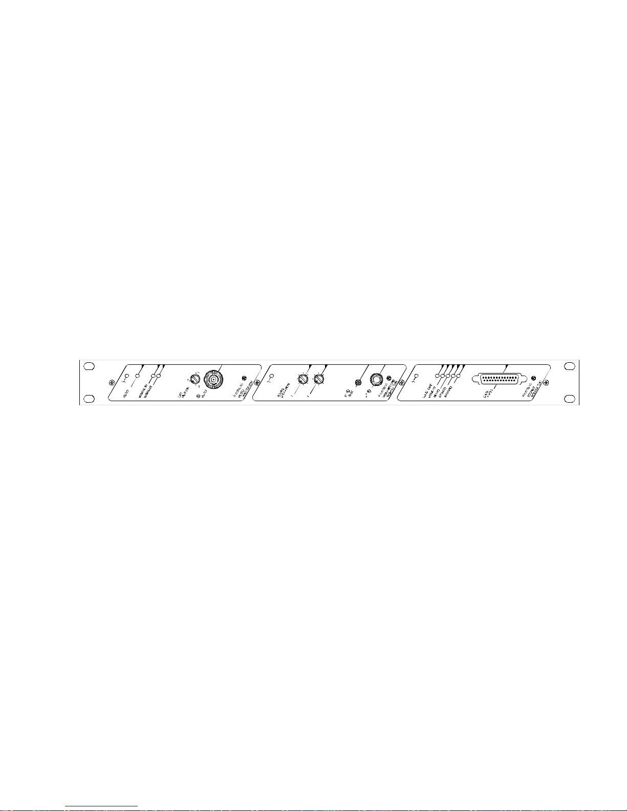
Interfaces
Module frontside
1 ... Lights up in the event of a module fault (red) - see data sheet 1763
2 ... Lights up, when a standard equivalent video signal is fed in at the
video main sync input (green)
3 ... Lights up, when the operating signal is switched through via the remote
control (yellow)
4 ... Lights up, when the substitute signal is switched through via the remote
control (yellow)
5 ... Setting of the video level (+/- 3 dB)
6 ... Monitoring output f or the vi deo signal
7 ... Lights red at module fault,see data sheet 1765
8 ... Potentiometer for the adjustment of the freq. deviation of sound1 (+/- 3 dB)
9 ... Potentiometer for the adjustment of the freq. deviation of sound2 (+/- 3 dB)
10 ... IF m onit oring output
11 ... Monitoring output f or audio si gnals 1/2
12 ... Lights at module fault (red), see data sheet 1766
13 ... Light s, when data line i s pr esent (green)
14 ... Lights, when the operation mode has been fixed over the remote
controll (PC) or over the control line (MODE) (yellow)
15 ... Light s at MONO oper at ion (yellow)
16 ... Light s at STEREO operation ( yell ow)
17 ... Lights at 2-SOUND operation (yellow)
18 ... Interfac e for a dat a processor
Operati on
Manual
ü
PAL modul ator 1 H U
2 - 11
Page 18

Module rear side
1 ... Fuse box (2 x 0.63 AT)
2 ... mains supply
3 ... St at us out put ( STATUS)
4 ... IF soun d car ri er 1+ 2 output (IF SND1+2 O UT)
5 ... IF sound carrier 2 output (IF SND2 OUT)
6 ... IF sound carrier 1 output (IF SND1 OUT)
7 ... IF vision carrier output (IF VIDEO OUT)
8 ... IF reference frequency input (IF REF. IN)
9 ... Video auxilliary input (VIDEO AUX. IN)
10 ... Unscrambled video input (VIDEO MAIN SYNC . IN)
11 ... Scrambled video input (VIDEO MAIN IN)
12 ... Audio auxil li ary input (SOU ND AU X. IN)
13 ... Audio input (SOUND MAIN IN)
Note:
For pin assignments see data sheet 1760
Operation
Manual
2 - 12
PAL modulator 1 HU
ü
Page 19

Putting the modulator into operation
Requirements
The modules should be correctly set. If they are not, read the instruction in the
data sheet.
NOTE:
If at all possible, u s e t he PC mo nit oring sof tware or an
oscilloscop e for putting the modulator into operation.
CAUTI ON :
If the main frame is steamed up after unpacking, allow it to
become a cclimat ed for at l east one hour before putting the
modulator i nto operation !
1. Feed in th e v i deo m ain signal (1 V pp, Black porch 0 V ), video mai n sync signal (1 Vpp), audio and reference signals.
2. Feed in the main voltage
3. Check to make sure no red LED lights up.
4. Check to make sure the green LED "VIDEO" lights up.
Putting t he video pr ocessor into operat ion
1. Turn the front panel potentiometer "VIDEO IN" until 700 mV white level is
displayed by t he PC mon it oring s of t ware.
If you put the video processor into operation without the PC monitoring software, connect an osci ll oscope t o the monitoring ou tput "V ID EO M ON.". S et
the amplitude of white value to 0,7 V.
Putting t he vision/sound
modulato r into operation
1. Set the deviation for a live signal with the potentiometer "SOUND DEVIATION" to a m ax imum of 30 kHz ( 30 k H z deviation corresponds to 1.55 V eff at
the monitoring output). Use the monitoring sotware or connect a suitable
measuring ins trum ent to the aud io monitoring output "AF MON.".
Putting the sound2 modulator into operat ion
1. Check to make sure the corresponding yellow LEDs lights up.
2. If you control the transmission mode (mono/stereo/ 2sound) by hardware, set
the pins at the connector "SO UND M AI N IN" in accordan ce with the table
"Transmission mode " - see dat a sheet 1760.
Operati on
Manual
ü
PAL modul ator 1 H U
2 - 13
Page 20

Help with problems
Video processor
Symptom Remedy
Red LED on Error in module video
- Check the fuse on the assembly (see data sheet 1760)
Green LED "VIDE O" off - No standar d sy nc pulse on the video main sync input
- Check the connecti ons on the r ear panel of m odule
No text insertion in the
substitute signal
although the EPROM
is fi tte d
- Check the input signal at the moni toring output
- Check the settings on the PC
Video processor fails t o
switch to the substitute
signal if the input signal is not present,
REMOT E LED on
Forced switch-through of the main input
- Check the settings on the PC
No output signal,
red LED off
LED "VIDEO" on,
LED "RE M AUX" off
Signal path in video processor is interrupted
- Check the switch settings in the m odule ( s ee D at a s heet )
No LED’s are on No operating voltage is being supplied to the module
- Check the operating voltage supply on the r ear panel
- Check the fuse on the assembly (see data sheet 1760)
Vision/sound modulator
Symptom Remedy
Red LED on Error i n module
- Check the fuse on the assembly (see data sheet 1760)
PLL unlocked from sound1 or no vision IF or no sound1 IF
- Check the settings on the PC
Vision car ri er i s not modulated ev en though a vid eo si gnal
complying with the standard is applied at the video main
sync. i nput
- Check the connections on the rear panel of module
Red LED l ight s up and
green LED "V ID EO" is
on
Video main sync. signal is present but no video main signal. -
- Check the connections on the rear panel of module.
Operation
Manual
2 - 14
PAL modulator 1 HU
ü
Page 21

Sound2 modulator
Symptom R emedy
Red LE D on Error in module
- Check the fuse on the assembly (see data sheet 1760)
PLL of VCO is unlocked from sound2 or Sound2 IF level is
too low or Sound2 is switched off
- Check the settings on th e PC
- Repla c e m odule
Operati on
Manual
ü
PAL modul ator 1 H U
2 - 15
Page 22

Operation
Manual
2 - 16
PAL modulator 1 HU
ü
Page 23

Service
Service
Manual
ü
PAL modul ator 1 H U
3 - 1
Page 24

Warning Note
WARNING:
Only trained staff are permitted to service the units
Adjustments
The factory adjustments of the modules can be found on the corresponding
data sheets.
To adj ust, open the m odul e on t he t op - the dat a s heets contai ns detailed
information.
Functional check
Check t he function of t he m odules wit h t he PC m onit oring program.
Handling
Storage
Store the modulator in the original packaging.
Consider this:
l
storage t empe rature -20 ... + 70oC
l
relative hum idi ty 20 . .. 80 %
Service
Manual
3 - 2
PAL modulator 1 HU
ü
Page 25

Equipment
PAL modulator 1 HU PM 501/1 976 934-001
Power supply 279 352
Assy video processor PL-VP 502/1 889 382-001
AUX assy video processor AUX-VP 50. 889 201-001
Assy vision/sound modulator PL-BTM 502/1 889 383-001
Assy sound2 modulator PL-T2M 501 889 204-001
Data processor DP 501/1 976 936-001
Rear panel assy PL-RW PM 501/1 889 358-001
IF matching unit 50/75 ZAF 501 976 935-001
IF locking ZFA 502/1 889 384-001
Remote record interface FSS 501/1 889 385-001
Eprom for cus tomer specific
text inser tion 879 190-504
Service
Manual
ü
PAL modul ator 1 H U
3 - 3
Page 26

Customer Service
Austr ia
Richard Hirschm ann Ges.m.b.H. Tel. +43-(0)5522/307 0
Oberer Paspelsweg 6-8 FAX +43-(0)5522/307 555
A-6830 RANKWEIL-BREDERIS
France
Richard Hirschm ann Tel. +33- (0)1/3933 02 80
Electron ique S.A. FAX +33- (0)1/3990 59 68
24, rue du Fer â Cheval, Z.I.
F-95200 SARCELLES
Germany
Richard Hirschm ann GmbH & Co Tel. +49-(0)7127/14 0
Stuttga rter Str. 45 - 51 F AX + 49-(0)7127/14 1214
D-72606 NECKARTEN ZLIN GE N
Great Britain
Electron ics UK Ltd. Tel. +44-(0 )1842/754 111
Burrell Way FAX +44- (0)1842/751 003
THETFORD, NORFOLK IP24 3RW
Hungary
Hirschmann-BHG Tel. +36-(0)1/149 7575
Rokolya u. 1-13 FAX +36- (0)1/129 8453
H-1131 BUDAPEST
Netherlands
Richard Hirschm ann Tel. +31- (0)294/462 555
Electron ica Nederland B.V. FAX +31- (0)294/480 639
Postbus 92
NL-1380 AB W EESP
Spain
Hirschm ann Espania S.A. Tel. +34- (0)1/754 0208
Calle Albala 7 FAX +34- (0)1/754 5177
E-28037 M AD RI D
USA
Richard Hirschm ann of America Inc.
Industrial Row Tel. +1-201/ 835 5002
P-O.Box 229 FAX +1- 201/ 835 8354
RIVER DALE, N.J. 07457
Service
Manual
3 - 4
PAL modulator 1 HU
ü
Page 27

Data sheets
Data shee ts
Manual
ü
PAL modul ator 1 H U
4 - 1
Page 28

Data sheet index
Ord. descri ption . . . . . . . . . . . . . . . . . . . . . . . . . . . . . . . . . . . . . . . . . . . . . . . . . . . . Sheet
PAL-Modulator 1 HU . . . . . . . . . . . . . . . . . . . . . . . . . . . . . . . . . . . . . . . . . . . . . . . . 1760
Assy video processor and AUX assy. . . . . . . . . . . . . . . . . . . . . . . . . . . . . . . . . . . . 1763
Assy vision/sound modulator and vision carr. locking . . . . . . . . . . . . . . . . . . . . . . . 1765
Assy sound2 modulat or . . . . . . . . . . . . . . . . . . . . . . . . . . . . . . . . . . . . . . . . . . . . . . 1766
IF mat ching unit . . . . . . . . . . . . . . . . . . . . . . . . . . . . . . . . . . . . . . . . . . . . . . . . . . . . 1768
IF locking . . . . . . . . . . . . . . . . . . . . . . . . . . . . . . . . . . . . . . . . . . . . . . . . . . . . . . . . . 1045
Remote record interface. . . . . . . . . . . . . . . . . . . . . . . . . . . . . . . . . . . . . . . . . . . . . . 1755
Rear panel as sy . . . . . . . . . . . . . . . . . . . . . . . . . . . . . . . . . . . . . . . . . . . . . . . . . . . . 1751
Data pr oces sor . . . . . . . . . . . . . . . . . . . . . . . . . . . . . . . . . . . . . . . . . . . . . . . . . . . . . 1185
Data sheet identification
Date
Date
Dep.
Ord. de script ion
XYZ
Ord. number
XXX
Sheet
1234.1.1/n
Data she ets
Manual
4 - 2
PAL modulator 1 HU
ü
 Loading...